EP2207069A2 - Element for supporting striking gongs in a timepiece - Google Patents
Element for supporting striking gongs in a timepiece Download PDFInfo
- Publication number
- EP2207069A2 EP2207069A2 EP09013673A EP09013673A EP2207069A2 EP 2207069 A2 EP2207069 A2 EP 2207069A2 EP 09013673 A EP09013673 A EP 09013673A EP 09013673 A EP09013673 A EP 09013673A EP 2207069 A2 EP2207069 A2 EP 2207069A2
- Authority
- EP
- European Patent Office
- Prior art keywords
- stamps
- timepiece
- support
- fixed
- fixed part
- Prior art date
- Legal status (The legal status is an assumption and is not a legal conclusion. Google has not performed a legal analysis and makes no representation as to the accuracy of the status listed.)
- Granted
Links
- 238000013016 damping Methods 0.000 claims description 7
- WKVZMKDXJFCMMD-UVWUDEKDSA-L (5ar,8ar,9r)-5-[[(2r,4ar,6r,7r,8r,8as)-7,8-dihydroxy-2-methyl-4,4a,6,7,8,8a-hexahydropyrano[3,2-d][1,3]dioxin-6-yl]oxy]-9-(4-hydroxy-3,5-dimethoxyphenyl)-5a,6,8a,9-tetrahydro-5h-[2]benzofuro[6,5-f][1,3]benzodioxol-8-one;azanide;n,3-bis(2-chloroethyl)-2-ox Chemical compound [NH2-].[NH2-].Cl[Pt+2]Cl.ClCCNP1(=O)OCCCN1CCCl.COC1=C(O)C(OC)=CC([C@@H]2C3=CC=4OCOC=4C=C3C(O[C@H]3[C@@H]([C@@H](O)[C@@H]4O[C@H](C)OC[C@H]4O3)O)[C@@H]3[C@@H]2C(OC3)=O)=C1 WKVZMKDXJFCMMD-UVWUDEKDSA-L 0.000 description 12
- 230000005540 biological transmission Effects 0.000 description 6
- 238000003466 welding Methods 0.000 description 4
- 239000011521 glass Substances 0.000 description 3
- 229910052751 metal Inorganic materials 0.000 description 3
- 239000002184 metal Substances 0.000 description 3
- BASFCYQUMIYNBI-UHFFFAOYSA-N platinum Chemical compound [Pt] BASFCYQUMIYNBI-UHFFFAOYSA-N 0.000 description 2
- 239000012080 ambient air Substances 0.000 description 1
- 239000000919 ceramic Substances 0.000 description 1
- 230000000295 complement effect Effects 0.000 description 1
- 239000013078 crystal Substances 0.000 description 1
- 230000001419 dependent effect Effects 0.000 description 1
- 229910003460 diamond Inorganic materials 0.000 description 1
- 239000010432 diamond Substances 0.000 description 1
- 239000013013 elastic material Substances 0.000 description 1
- 238000012423 maintenance Methods 0.000 description 1
- 239000000463 material Substances 0.000 description 1
- 230000002093 peripheral effect Effects 0.000 description 1
- 239000011295 pitch Substances 0.000 description 1
- 229910052697 platinum Inorganic materials 0.000 description 1
- 229910052594 sapphire Inorganic materials 0.000 description 1
- 239000010980 sapphire Substances 0.000 description 1
- 229910001220 stainless steel Inorganic materials 0.000 description 1
- 239000010935 stainless steel Substances 0.000 description 1
Images


Classifications
-
- G—PHYSICS
- G04—HOROLOGY
- G04B—MECHANICALLY-DRIVEN CLOCKS OR WATCHES; MECHANICAL PARTS OF CLOCKS OR WATCHES IN GENERAL; TIME PIECES USING THE POSITION OF THE SUN, MOON OR STARS
- G04B21/00—Indicating the time by acoustic means
- G04B21/02—Regular striking mechanisms giving the full hour, half hour or quarter hour
- G04B21/08—Sounding bodies; Whistles; Musical apparatus
-
- G—PHYSICS
- G04—HOROLOGY
- G04B—MECHANICALLY-DRIVEN CLOCKS OR WATCHES; MECHANICAL PARTS OF CLOCKS OR WATCHES IN GENERAL; TIME PIECES USING THE POSITION OF THE SUN, MOON OR STARS
- G04B23/00—Arrangements producing acoustic signals at preselected times
- G04B23/02—Alarm clocks
- G04B23/026—Hammer driving; hammers; devices with several hammers or sounding bodies; vibrators
-
- G—PHYSICS
- G04—HOROLOGY
- G04B—MECHANICALLY-DRIVEN CLOCKS OR WATCHES; MECHANICAL PARTS OF CLOCKS OR WATCHES IN GENERAL; TIME PIECES USING THE POSITION OF THE SUN, MOON OR STARS
- G04B23/00—Arrangements producing acoustic signals at preselected times
- G04B23/02—Alarm clocks
- G04B23/028—Sounding bodies; boxes used as sounding cases; fixation on or in the case
Definitions
- the present invention relates to a support for fixing ringing tones to a fixed part of a timepiece, as well as a timepiece comprising it.
- Ringing timepieces are known to include vibrating elements called “timbres” and hammers that strike the timbres to make them sound and make them produce sounds.
- the stamps are generally in the form of bent wire extending in one or more planes parallel to the plane of the dial of the timepiece. They are fixed by one of their ends to a piece called "heel" itself attached to a fixed part of the timepiece such as the platinum movement, middle part or ice. Fixing a stamp in the heel is generally performed by driving and welding the end of the stamp attachment in the heel. The heel is usually attached to the fixed part of the timepiece by screws. Examples of stamp arrangements are described in the documents CH 313 202 , WO 20061095244 and EP 1,906,267 .
- connection between a timbre and the fixed part must be as rigid as possible to ensure good transmission of sound to the outside of the timepiece.
- the vibrations of the stamps farthest from the fixed part must pass through a large number of fixing zones, namely the connection between the stamps and their connecting heel, the connection or links between the heels and the link between the heel in contact with the fixed part and the latter. Acoustic losses occur in each of these attachment areas.
- the present invention aims to provide a support for ringing timbres of a timepiece that can receive a large number of stamps while ensuring good sound transmission.
- a support for connecting ringing tones to a fixed part of a timepiece characterized in that it comprises a stepped face defining steps on which end portions of the stamps can respectively be fixed.
- the support according to the invention can receive a large number of stamps, for example three, four or more. These stamps can be superimposed in the axial direction of the timepiece box and thus occupy only the place of a stamp radially.
- the parallelism of the stamps can be well controlled by positioning a bearing face of the end portion of each stamp on the corresponding step. Because the stamps can be connected to the fixed part via a single piece, namely the support according to the invention, a good sound transmission can be provided between each of these stamps and the fixed part. .
- a timepiece such as a watch, in particular a wristwatch, comprises a box formed of a caseband, an ice and a bottom, of which only the ice 1 is shown in FIG. the figure 1 .
- a movement whose plate 2 is shown schematically in dotted lines and which is surmounted by a dial (not shown) visible through the glass 1, and a striking mechanism such as a mechanism minute repeater, big ring, small bell or alarm clock.
- a mechanism minute repeater such as a mechanism minute repeater, big ring, small bell or alarm clock.
- these stamps 3 are four in number. They are intended to be struck by respective hammers of the striking mechanism to enter vibration.
- the vibrations produced are transmitted to the box of the timepiece to be radiated acoustically outwards.
- the timbres 3 have different lengths so that they produce different musical notes when struck.
- These stamps 3 are in the form of 4 curved son in an arc around the axis A of the box and each terminated by a rigid end portion 5 of greater width.
- the end portion 5 may have a flat shape, rectangular in section and in plan view, as shown.
- the wires 4 preferably have a rectangular section.
- the end portions 5 of the stamps 3 are fixed to a support 6 itself attached to a fixed part of the timepiece, namely the glass 1.
- the stamps 3 are located axially (that is to say in the direction of the axis A) between the plate 2 and the bridges of the movement.
- the support 6 is arranged radially between the middle and the periphery of the plate 2, in a peripheral recess of the plate 2, and connects the stamps 3 to the ice 1 without touching the plate 2 nor the middle part.
- the support 6 is made in one piece and is in the form of a circular arc wall coaxial with the box.
- One of its flanks constitutes a stepped face 7 (cf. Figures 1 and 2 ) defining steps 8 on which are maintained the end portions 5 of the stamps 3 respectively, the other ends 9 of the stamps 3 remaining free.
- the stamps 3 are thus held in respective planes which are parallel to the plane of the dial and perpendicular to the axis A, and are superimposed in the direction of the axis A so as to occupy the place of a stamp radially.
- the end portion 5 of each stamp 3 comprises a flat bearing face 10 which is parallel to the aforementioned planes and to the corresponding step 8 and maintained in abutment against the latter.
- the support 6 is fixed to the mirror 1 by its sidewall 12 opposite to the staircase face 7.
- This sidewall 12 comprises a central recess 13 which defines two feet 14 of the support 6 in contact with the glass 1.
- the attachment of the support 6 is performed by welding feet 14 to ice 1.
- the support 6 constitutes a very rigid connection between the stamps 3 and the ice 1 and thus ensures a good transmission of the vibrations of the stamps 3 to the ice 1. These vibrations are then radiated in the ambient air by the ice 1 and the other elements of the box so that the user perceives a sound each time a stamp 3 is struck. Because it is not in contact with the plate 2, the support 6 prevents vibrations from having to cross the plate. movement and suffer losses.
- the recess 13 defines clear and well defined contact zones between the support 6 and the ice 1, namely the bearing surfaces of the feet 14. A very homogeneous welding of the support 6 on the ice 1 can thus be obtained, which further improves the transmission of sound.
- a large number of stamps 3 can be attached to the support 6 while respecting the parallelism mentioned above.
- the support 6 is made of a material in which the sound velocity is high, for example ceramic, sapphire, diamond or a metal such as stainless steel.
- a metal deposit is first made on the area of the ice 1 intended to receive the feet 14 as well as on the support surface of the feet 14 if the support 6 is not made of metal .
- the support 6 could be attached to another fixed part of the timepiece than the ice 1, in particular to another element of the box such as the middle part.
- the steps 8 of the stepped face 7 and the bearing faces 10 of the end portions 5 of the stamps 3 may not be planar provided that they are complementary and that they position the stamps 3 in a parallel manner between them.
- these steps 8 and these bearing faces 10 could be spherical or V.
- the removable connection means constituted by the screws 11 allow the stamps 3 to be detached from the support 6 and removed to make certain components of the movement accessible during adjustment, maintenance or repair of the workpiece. watchmaking.
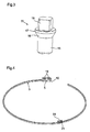
- the figure 3 shows the shape of the screws 11 according to a preferred embodiment.
- the screws 11 comprise successively a threaded cylindrical portion 15, a conical portion 16, a cylindrical portion 17 of larger diameter than the portion 15 and a head 18 of polygonal section, for example square, the conical portion 16 being flared towards the head 18
- the screws 11 pass through holes 19 of the end portions 5 (cf. figure 4 ) and are screwed into tapped holes 20 of the support 6 (Cf. figure 2 ).
- the holes 19 have a conical wall on which the conical portion 16 of the screws 11 rests. This screw shape makes it possible for the end parts 5 of the stamps 3 to be tightly clamped against the support 6.
- the obtuse angle The conical portion 16 with the threaded cylindrical portion 15 increases the resistance of the screw to the shear forces so that a high clamping moment can be applied to the screw without risk of breakage.
- the polygonal section head 18 can be received in a correspondingly shaped hole of a tool and thus provides a large bearing surface for such a tool to exert the tightening torque. It has been found that the use of such screws 11 in place of traditional screws, because a large tightening moment can be applied to them, significantly improves the transmission of the vibrations of the stamps 3 to the ice 1.
- the free ends 9 of the stamps 3 are aligned in the direction of the axis A of the box.
- the stamps 3 can have a great length since they can all stop just before the support 6. This great length allows the stamps 3 to hold their note longer.
- the fact that the ends 9 are aligned axially gives an unusual and attractive aesthetic character to the striking mechanism.
- the intervals between the note pitches of the stamps 3 can be adjusted by varying the shape and / or the size of the section of each stamp 3, for example by conforming each stamp 3 with a section of shape and / or variable size.
- the stamps 3 comprise a recess 21 in which is fixed, for example by force, a damping element 22 of elastic material.
- Each damping element 22 protrudes from the surface of the stamp 3 in which it is placed in the axial direction to provide a bearing surface to the stamp 3 which it is facing in the case of relative axial movements of the stamps 3 during movements undergone by the timepiece.
- These damping elements 22 are placed in the zones of the stamps 3 which deform more axially. They avoid that the stamps 3 collide directly and produce stray sounds during the movements to wear.
Abstract
Description
La présente invention concerne un support destiné à fixer des timbres de sonnerie à une partie fixe d'une pièce d'horlogerie, ainsi qu'une pièce d'horlogerie le comprenant.The present invention relates to a support for fixing ringing tones to a fixed part of a timepiece, as well as a timepiece comprising it.
On sait que les pièces d'horlogerie à sonnerie comportent des éléments vibrants appelés « timbres » et des marteaux qui frappent les timbres pour les faire résonner et leur faire produire ainsi des sons.Ringing timepieces are known to include vibrating elements called "timbres" and hammers that strike the timbres to make them sound and make them produce sounds.
Les timbres sont généralement sous la forme de fils métalliques cintrés s'étendant dans un ou des plans parallèles au plan du cadran de la pièce d'horlogerie. Ils sont fixés par l'une de leurs extrémités à une pièce appelée « talon » elle-même fixée à une partie fixe de la pièce d'horlogerie telle que la platine du mouvement, la carrure ou la glace. La fixation d'un timbre au talon est réalisée généralement par chassage et soudage de l'extrémité d'attache du timbre dans le talon. Le talon est lui généralement fixé sur la partie fixe de la pièce d'horlogerie par des vis. Des exemples d'agencements de timbres sont décrits dans les documents
Il est connu, notamment par les deux derniers documents précités, de fixer deux timbres à un même talon. Lorsque la pièce d'horlogerie comporte plus de deux timbres, on prévoit plusieurs talons superposés recevant chacun un ou deux timbres. A la connaissance de la demanderesse, on ne fixe jamais plus de deux timbres à un même talon car le parallélisme des timbres n'est alors pas maîtrisé.It is known, in particular by the last two aforementioned documents, to fix two stamps to one and the same heel. When the timepiece has more than two stamps, there are provided several superposed heels each receiving one or two stamps. To the plaintiff's knowledge, no more than two stamps are fixed at one and the same heel because the parallelism of the stamps is then not mastered.
On sait également que la liaison entre un timbre et la partie fixe doit être la plus rigide possible pour assurer une bonne transmission du son vers l'extérieur de la pièce d'horlogerie. Lorsque plusieurs talons sont utilisés, les vibrations des timbres les plus éloignés de la partie fixe doivent traverser un grand nombre de zones de fixation, à savoir la liaison entre les timbres et leur talon de rattachement, la ou les liaisons entre les talons et la liaison entre le talon en contact avec la partie fixe et cette dernière. Des pertes acoustiques surviennent dans chacune de ces zones de fixation.It is also known that the connection between a timbre and the fixed part must be as rigid as possible to ensure good transmission of sound to the outside of the timepiece. When several heels are used, the vibrations of the stamps farthest from the fixed part must pass through a large number of fixing zones, namely the connection between the stamps and their connecting heel, the connection or links between the heels and the link between the heel in contact with the fixed part and the latter. Acoustic losses occur in each of these attachment areas.
La présente invention vise à proposer un support pour des timbres de sonnerie d'une pièce d'horlogerie qui puisse recevoir un grand nombre de timbres tout en assurant une bonne transmission du son.The present invention aims to provide a support for ringing timbres of a timepiece that can receive a large number of stamps while ensuring good sound transmission.
A cette fin est prévu un support destiné à relier des timbres de sonnerie à une partie fixe d'une pièce d'horlogerie, caractérisé par le fait qu'il comprend une face en escalier définissant des marches sur lesquelles des parties d'extrémité des timbres peuvent respectivement être fixées.To this end is provided a support for connecting ringing tones to a fixed part of a timepiece, characterized in that it comprises a stepped face defining steps on which end portions of the stamps can respectively be fixed.
Grâce à cette face en escalier servant d'appui aux timbres, le support selon l'invention peut recevoir un grand nombre de timbres, par exemple trois, quatre, voire plus. Ces timbres peuvent être superposés dans la direction axiale de la boîte de la pièce d'horlogerie et ainsi occuper uniquement la place d'un timbre radialement. Le parallélisme des timbres peut être bien maîtrisé en positionnant une face d'appui de la partie d'extrémité de chaque timbre sur la marche correspondante. Du fait que les timbres peuvent être reliés à la partie fixe par l'intermédiaire d'une seule et même pièce, à savoir le support selon l'invention, une bonne transmission du son peut être assurée entre chacun de ces timbres et la partie fixe.With this stepped face serving as a support for the stamps, the support according to the invention can receive a large number of stamps, for example three, four or more. These stamps can be superimposed in the axial direction of the timepiece box and thus occupy only the place of a stamp radially. The parallelism of the stamps can be well controlled by positioning a bearing face of the end portion of each stamp on the corresponding step. Because the stamps can be connected to the fixed part via a single piece, namely the support according to the invention, a good sound transmission can be provided between each of these stamps and the fixed part. .
Des modes de réalisation particuliers de l'invention sont définis dans les revendications dépendantes annexées.Particular embodiments of the invention are defined in the appended dependent claims.
D'autres caractéristiques et avantages de la présente invention apparaîtront à la lecture de la description détaillée suivante faite en référence aux dessins annexés dans lesquels :
- la
figure 1 est une vue en perspective montrant le support selon l'invention reliant des timbres à une glace de pièce d'horlogerie ; - la
figure 2 est une vue en perspective du support seul ; - la
figure 3 est une vue en perspective montrant une forme avantageuse de vis utilisées pour fixer les timbres au support ; - la
figure 4 est une vue en perspective de l'un des timbres fixés au support, montrant notamment de façon éclatée un élément amortisseur logé dans ce timbre ; - la
figure 5 est une vue en perspective des timbres, montrant des éléments amortisseurs logés dans certains d'entre eux ainsi que des extrémités libres alignées de ces timbres ; - la
figure 6 est une vue plane partielle de profil des timbres, montrant les éléments amortisseurs logés dans certains d'entre eux.
- the
figure 1 is a perspective view showing the support according to the invention connecting timbres to a timepiece crystal; - the
figure 2 is a perspective view of the support alone; - the
figure 3 is a perspective view showing an advantageous form of screws used to fix the stamps to the support; - the
figure 4 is a perspective view of one of the stamps attached to the support, showing in particular exploded a damping element housed in this stamp; - the
figure 5 is a perspective view of the stamps, showing damping elements housed in some of them as well as aligned free ends of these stamps; - the
figure 6 is a partial flat profile view of the stamps, showing the damping elements housed in some of them.
En référence à la
Les parties d'extrémité 5 des timbres 3 sont fixées à un support 6 lui-même fixé à une partie fixe de la pièce d'horlogerie, à savoir la glace 1. Les timbres 3 sont situés axialement (c'est-à-dire dans la direction de l'axe A) entre la platine 2 et les ponts du mouvement. Le support 6 est disposé radialement entre la carrure et le pourtour de la platine 2, dans un évidement périphérique de la platine 2, et relie les timbres 3 à la glace 1 sans toucher ni la platine 2 ni la carrure.The
Le support 6 est réalisé en une seule pièce et se présente sous la forme d'une paroi en arc de cercle coaxiale avec la boîte. L'un de ses flancs constitue une face en escalier 7 (cf.
Le support 6 est fixé à la glace 1 par son flanc 12 opposé à la face en escalier 7. Ce flanc 12 comporte un évidement central 13 qui définit deux pieds 14 du support 6 en contact avec la glace 1. La fixation du support 6 est réalisée par soudage des pieds 14 à la glace 1.The
Par son caractère massif, le support 6 constitue une liaison bien rigide entre les timbres 3 et la glace 1 et assure donc une bonne transmission des vibrations des timbres 3 à la glace 1. Ces vibrations sont ensuite rayonnées dans l'air ambiant par la glace 1 et les autres éléments de la boîte de sorte que l'utilisateur perçoit un son à chaque fois qu'un timbre 3 est frappé. Du fait qu'il n'est pas en contact avec la platine 2, le support 6 évite aux vibrations de devoir traverser le mouvement et d'y subir des pertes. L'évidement 13 définit des zones de contact franches et bien déterminées entre le support 6 et la glace 1, à savoir les surfaces d'appui des pieds 14. Un soudage bien homogène du support 6 sur la glace 1 peut ainsi être obtenu, ce qui améliore encore la transmission du son. Enfin, grâce à la face en escalier 7, un grand nombre de timbres 3 peuvent être fixés au support 6 tout en respectant le parallélisme mentionné plus haut.By its massive nature, the
Le support 6 est fait dans une matière dans laquelle la célérité du son est élevée, par exemple la céramique, le saphir, le diamant ou un métal tel que l'acier inoxydable. Pour le soudage du support 6 à la glace 1 on effectue préalablement un dépôt métallique sur la zone de la glace 1 destinée à recevoir les pieds 14 ainsi que sur la surface d'appui des pieds 14 si le support 6 n'est pas en métal.The
Dans une variante, le support 6 pourrait être fixé à une autre partie fixe de la pièce d'horlogerie que la glace 1, notamment à un autre élément de la boîte tel que la carrure.Alternatively, the
Les marches 8 de la face en escalier 7 et les faces d'appui 10 des parties d'extrémité 5 des timbres 3 pourraient ne pas être planes pour autant qu'elles soient complémentaires et qu'elles permettent de positionner les timbres 3 de manière parallèle entre eux. Par exemple, ces marches 8 et ces faces d'appui 10 pourraient être sphériques ou en V.The
Les moyens de liaison démontable que constituent les vis 11 permettent aux timbres 3 d'être désolidarisés du support 6 et retirés pour rendre accessibles certains composants du mouvement lors d'un réglage, d'un entretien ou d'une réparation de la pièce d'horlogerie.The removable connection means constituted by the
La
Selon une autre caractéristique de l'invention, montrée à la
Selon encore une autre caractéristique de l'invention, visible aux
Claims (12)
Applications Claiming Priority (1)
| Application Number | Priority Date | Filing Date | Title |
|---|---|---|---|
| CH00030/09A CH700212B1 (en) | 2009-01-12 | 2009-01-12 | Support for timepiece ringing stamps. |
Publications (3)
| Publication Number | Publication Date |
|---|---|
| EP2207069A2 true EP2207069A2 (en) | 2010-07-14 |
| EP2207069A3 EP2207069A3 (en) | 2016-11-30 |
| EP2207069B1 EP2207069B1 (en) | 2018-06-13 |
Family
ID=41264247
Family Applications (1)
| Application Number | Title | Priority Date | Filing Date |
|---|---|---|---|
| EP09013673.0A Active EP2207069B1 (en) | 2009-01-12 | 2009-10-30 | Element for supporting striking gongs in a timepiece |
Country Status (4)
| Country | Link |
|---|---|
| EP (1) | EP2207069B1 (en) |
| JP (1) | JP5566118B2 (en) |
| CN (1) | CN101825862B (en) |
| CH (1) | CH700212B1 (en) |
Cited By (7)
| Publication number | Priority date | Publication date | Assignee | Title |
|---|---|---|---|---|
| JP2012058232A (en) * | 2010-09-13 | 2012-03-22 | Montres Breguet Sa | Timepiece with gonging function including gong separation device |
| CH707078A1 (en) * | 2012-10-15 | 2014-04-15 | Société Anonyme De La Manufacture D Horlogerie Audemars Piguet & Cie | Stamp for striking work of a timepiece. |
| WO2015039883A1 (en) * | 2013-09-19 | 2015-03-26 | Chopard Technologies Sa | Time piece including a case closed by a crystal and a striking mechanism |
| US9164487B1 (en) | 2014-05-07 | 2015-10-20 | Société Anonyme de la Manufacture d'Horlogerie Audemars Piguet & Cie | Striking watch |
| EP3657268A1 (en) * | 2018-11-22 | 2020-05-27 | Blancpain SA | Resonant member for a chiming mechanism of a watch or a music box |
| EP3657269A1 (en) * | 2018-11-22 | 2020-05-27 | Blancpain SA | Resonant member for a chiming mechanism of a watch or a music box |
| EP3657267A1 (en) * | 2018-11-22 | 2020-05-27 | Blancpain SA | Resonant member for a chiming mechanism of a watch or a music box |
Families Citing this family (4)
| Publication number | Priority date | Publication date | Assignee | Title |
|---|---|---|---|---|
| CH704198A2 (en) * | 2010-12-10 | 2012-06-15 | Montres Breguet Sa | Striking mechanism for striking watch, has movable and fixed elements arranged on striking portion and gong part, respectively, where hammer is driven toward gong to vibrate gong by pulse due to repulsive force of elements in striking mode |
| EP2942674B1 (en) * | 2014-05-06 | 2018-10-03 | Blancpain SA. | Assembly for generating a chime of a chiming mechanism |
| DE102014114969B3 (en) * | 2014-10-15 | 2015-04-23 | Lange Uhren Gmbh | Clock |
| CH719618A1 (en) * | 2022-04-22 | 2023-10-31 | Richemont Int Sa | Chime bell attached to a timepiece crystal |
Citations (3)
| Publication number | Priority date | Publication date | Assignee | Title |
|---|---|---|---|---|
| CH313202A (en) | 1953-06-25 | 1956-03-31 | Manuf Des Montres Et Chronogra | Alarm clock |
| WO2006095244A2 (en) | 2005-03-11 | 2006-09-14 | Richemont International Sa | Device for fixing at least one striking gong in a timepiece and method of fixing at least one striking gong in a timepiece |
| EP1906267A1 (en) | 2006-09-26 | 2008-04-02 | Montres Breguet S.A. | Chiming watch |
Family Cites Families (2)
| Publication number | Priority date | Publication date | Assignee | Title |
|---|---|---|---|---|
| CN2831191Y (en) * | 2005-09-15 | 2006-10-25 | 杭州手表有限公司 | Two-asking time reporting mechanism of clock |
| ES2369147T3 (en) * | 2006-10-12 | 2011-11-25 | Christophe Claret Sa | TIMBRE INSULATION. |
-
2009
- 2009-01-12 CH CH00030/09A patent/CH700212B1/en not_active IP Right Cessation
- 2009-10-30 EP EP09013673.0A patent/EP2207069B1/en active Active
-
2010
- 2010-01-05 CN CN201010002132.XA patent/CN101825862B/en not_active Expired - Fee Related
- 2010-01-12 JP JP2010003833A patent/JP5566118B2/en active Active
Patent Citations (3)
| Publication number | Priority date | Publication date | Assignee | Title |
|---|---|---|---|---|
| CH313202A (en) | 1953-06-25 | 1956-03-31 | Manuf Des Montres Et Chronogra | Alarm clock |
| WO2006095244A2 (en) | 2005-03-11 | 2006-09-14 | Richemont International Sa | Device for fixing at least one striking gong in a timepiece and method of fixing at least one striking gong in a timepiece |
| EP1906267A1 (en) | 2006-09-26 | 2008-04-02 | Montres Breguet S.A. | Chiming watch |
Cited By (13)
| Publication number | Priority date | Publication date | Assignee | Title |
|---|---|---|---|---|
| JP2012058232A (en) * | 2010-09-13 | 2012-03-22 | Montres Breguet Sa | Timepiece with gonging function including gong separation device |
| CH707078A1 (en) * | 2012-10-15 | 2014-04-15 | Société Anonyme De La Manufacture D Horlogerie Audemars Piguet & Cie | Stamp for striking work of a timepiece. |
| US9292004B2 (en) | 2012-10-15 | 2016-03-22 | Société Anonyme de la Manufacture d'Horlogerie Audemars Piguet & Cie | Gong for striking-work device of a timepiece |
| CH708597A1 (en) * | 2013-09-19 | 2015-03-31 | Chopard Technologies Sa | Timepiece including a case closed by a crystal and a striking mechanism. |
| WO2015039883A1 (en) * | 2013-09-19 | 2015-03-26 | Chopard Technologies Sa | Time piece including a case closed by a crystal and a striking mechanism |
| US9164487B1 (en) | 2014-05-07 | 2015-10-20 | Société Anonyme de la Manufacture d'Horlogerie Audemars Piguet & Cie | Striking watch |
| EP2942675A1 (en) * | 2014-05-07 | 2015-11-11 | Société anonyme de la Manufacture d'Horlogerie Audemars Piguet & Cie | Chiming watch |
| EP3657268A1 (en) * | 2018-11-22 | 2020-05-27 | Blancpain SA | Resonant member for a chiming mechanism of a watch or a music box |
| EP3657269A1 (en) * | 2018-11-22 | 2020-05-27 | Blancpain SA | Resonant member for a chiming mechanism of a watch or a music box |
| EP3657267A1 (en) * | 2018-11-22 | 2020-05-27 | Blancpain SA | Resonant member for a chiming mechanism of a watch or a music box |
| US11681259B2 (en) | 2018-11-22 | 2023-06-20 | Blancpain Sa | Resonant member for a striking mechanism of a watch or of a music box |
| US11774910B2 (en) | 2018-11-22 | 2023-10-03 | Blancpain Sa | Resonant member for a striking mechanism of a watch or of a music box |
| US11842713B2 (en) | 2018-11-22 | 2023-12-12 | Blancpain Sa | Resonant member for a striking mechanism of a watch or of a music box |
Also Published As
| Publication number | Publication date |
|---|---|
| CN101825862A (en) | 2010-09-08 |
| EP2207069B1 (en) | 2018-06-13 |
| EP2207069A3 (en) | 2016-11-30 |
| CN101825862B (en) | 2014-02-19 |
| JP5566118B2 (en) | 2014-08-06 |
| CH700212B1 (en) | 2013-11-29 |
| CH700212A2 (en) | 2010-07-15 |
| JP2010160155A (en) | 2010-07-22 |
Similar Documents
| Publication | Publication Date | Title |
|---|---|---|
| EP2207069B1 (en) | Element for supporting striking gongs in a timepiece | |
| WO2006095244A2 (en) | Device for fixing at least one striking gong in a timepiece and method of fixing at least one striking gong in a timepiece | |
| EP1906267B1 (en) | Chiming watch | |
| EP1914606B1 (en) | Gong isolator | |
| EP1837719A1 (en) | Balance for a clock movement | |
| EP2367077A1 (en) | Glass-bezel assembly for a timepiece and assembly method | |
| CH708095B1 (en) | Ringing mechanism provided with means for selecting the vibratory mode of a gong. | |
| EP2362278B1 (en) | Hammer for a stricking mechanism of a watch | |
| EP2942674B1 (en) | Assembly for generating a chime of a chiming mechanism | |
| EP2228693A1 (en) | Fixing device for the gongs of a sonnerie watch | |
| EP3712712A1 (en) | Dial for a timepiece provided with a three-dimensional decoration | |
| EP1760549A1 (en) | Gong for a striking mechanism in a timepiece | |
| EP3047339B1 (en) | Time piece including a case closed by a crystal and a striking mechanism | |
| EP3537228A1 (en) | Device for adjusting the vibration frequency of a bell of a chiming mechanism | |
| CH709903A2 (en) | All removable clock. | |
| CH708036A2 (en) | sound generator for watch and clock device equipped with a generator. | |
| CH707061B1 (en) | Ring timbre for timepieces. | |
| FR2562398A1 (en) | Bracelet with links | |
| CH716149A1 (en) | Clockwork movement comprising at least one gong. | |
| EP3835883A1 (en) | Arrangement for holding and vibration transmission of an acoustic radiation membrane in a watch case | |
| WO2022118102A1 (en) | Device for assembling two timepiece components | |
| CH716927A2 (en) | Arrangement for maintaining and transmitting an acoustic radiation membrane in a watch case. | |
| EP4250020A1 (en) | Watch case with rotating bezel | |
| EP2590034B1 (en) | Chiming watch | |
| CH715967A2 (en) | Dial of a timepiece with three-dimensional decor. |
Legal Events
| Date | Code | Title | Description |
|---|---|---|---|
| PUAI | Public reference made under article 153(3) epc to a published international application that has entered the european phase |
Free format text: ORIGINAL CODE: 0009012 |
|
| AK | Designated contracting states |
Kind code of ref document: A2 Designated state(s): AT BE BG CH CY CZ DE DK EE ES FI FR GB GR HR HU IE IS IT LI LT LU LV MC MK MT NL NO PL PT RO SE SI SK SM TR |
|
| AX | Request for extension of the european patent |
Extension state: AL BA RS |
|
| PUAL | Search report despatched |
Free format text: ORIGINAL CODE: 0009013 |
|
| AK | Designated contracting states |
Kind code of ref document: A3 Designated state(s): AT BE BG CH CY CZ DE DK EE ES FI FR GB GR HR HU IE IS IT LI LT LU LV MC MK MT NL NO PL PT RO SE SI SK SM TR |
|
| AX | Request for extension of the european patent |
Extension state: AL BA RS |
|
| RIC1 | Information provided on ipc code assigned before grant |
Ipc: G04B 23/02 20060101ALI20161021BHEP Ipc: G04B 21/08 20060101AFI20161021BHEP |
|
| 17P | Request for examination filed |
Effective date: 20170131 |
|
| RBV | Designated contracting states (corrected) |
Designated state(s): AT BE BG CH CY CZ DE DK EE ES FI FR GB GR HR HU IE IS IT LI LT LU LV MC MK MT NL NO PL PT RO SE SI SK SM TR |
|
| GRAP | Despatch of communication of intention to grant a patent |
Free format text: ORIGINAL CODE: EPIDOSNIGR1 |
|
| INTG | Intention to grant announced |
Effective date: 20180123 |
|
| GRAS | Grant fee paid |
Free format text: ORIGINAL CODE: EPIDOSNIGR3 |
|
| GRAA | (expected) grant |
Free format text: ORIGINAL CODE: 0009210 |
|
| AK | Designated contracting states |
Kind code of ref document: B1 Designated state(s): AT BE BG CH CY CZ DE DK EE ES FI FR GB GR HR HU IE IS IT LI LT LU LV MC MK MT NL NO PL PT RO SE SI SK SM TR |
|
| REG | Reference to a national code |
Ref country code: GB Ref legal event code: FG4D Free format text: NOT ENGLISH |
|
| REG | Reference to a national code |
Ref country code: CH Ref legal event code: EP Ref country code: AT Ref legal event code: REF Ref document number: 1009096 Country of ref document: AT Kind code of ref document: T Effective date: 20180615 |
|
| REG | Reference to a national code |
Ref country code: IE Ref legal event code: FG4D Free format text: LANGUAGE OF EP DOCUMENT: FRENCH |
|
| REG | Reference to a national code |
Ref country code: DE Ref legal event code: R096 Ref document number: 602009052725 Country of ref document: DE |
|
| REG | Reference to a national code |
Ref country code: CH Ref legal event code: NV Representative=s name: MICHELI AND CIE SA, CH |
|
| REG | Reference to a national code |
Ref country code: NL Ref legal event code: MP Effective date: 20180613 |
|
| REG | Reference to a national code |
Ref country code: LT Ref legal event code: MG4D |
|
| PG25 | Lapsed in a contracting state [announced via postgrant information from national office to epo] |
Ref country code: CY Free format text: LAPSE BECAUSE OF FAILURE TO SUBMIT A TRANSLATION OF THE DESCRIPTION OR TO PAY THE FEE WITHIN THE PRESCRIBED TIME-LIMIT Effective date: 20180613 Ref country code: LT Free format text: LAPSE BECAUSE OF FAILURE TO SUBMIT A TRANSLATION OF THE DESCRIPTION OR TO PAY THE FEE WITHIN THE PRESCRIBED TIME-LIMIT Effective date: 20180613 Ref country code: FI Free format text: LAPSE BECAUSE OF FAILURE TO SUBMIT A TRANSLATION OF THE DESCRIPTION OR TO PAY THE FEE WITHIN THE PRESCRIBED TIME-LIMIT Effective date: 20180613 Ref country code: NO Free format text: LAPSE BECAUSE OF FAILURE TO SUBMIT A TRANSLATION OF THE DESCRIPTION OR TO PAY THE FEE WITHIN THE PRESCRIBED TIME-LIMIT Effective date: 20180913 Ref country code: SE Free format text: LAPSE BECAUSE OF FAILURE TO SUBMIT A TRANSLATION OF THE DESCRIPTION OR TO PAY THE FEE WITHIN THE PRESCRIBED TIME-LIMIT Effective date: 20180613 Ref country code: ES Free format text: LAPSE BECAUSE OF FAILURE TO SUBMIT A TRANSLATION OF THE DESCRIPTION OR TO PAY THE FEE WITHIN THE PRESCRIBED TIME-LIMIT Effective date: 20180613 Ref country code: BG Free format text: LAPSE BECAUSE OF FAILURE TO SUBMIT A TRANSLATION OF THE DESCRIPTION OR TO PAY THE FEE WITHIN THE PRESCRIBED TIME-LIMIT Effective date: 20180913 |
|
| PG25 | Lapsed in a contracting state [announced via postgrant information from national office to epo] |
Ref country code: GR Free format text: LAPSE BECAUSE OF FAILURE TO SUBMIT A TRANSLATION OF THE DESCRIPTION OR TO PAY THE FEE WITHIN THE PRESCRIBED TIME-LIMIT Effective date: 20180914 Ref country code: LV Free format text: LAPSE BECAUSE OF FAILURE TO SUBMIT A TRANSLATION OF THE DESCRIPTION OR TO PAY THE FEE WITHIN THE PRESCRIBED TIME-LIMIT Effective date: 20180613 Ref country code: HR Free format text: LAPSE BECAUSE OF FAILURE TO SUBMIT A TRANSLATION OF THE DESCRIPTION OR TO PAY THE FEE WITHIN THE PRESCRIBED TIME-LIMIT Effective date: 20180613 |
|
| REG | Reference to a national code |
Ref country code: AT Ref legal event code: MK05 Ref document number: 1009096 Country of ref document: AT Kind code of ref document: T Effective date: 20180613 |
|
| PG25 | Lapsed in a contracting state [announced via postgrant information from national office to epo] |
Ref country code: NL Free format text: LAPSE BECAUSE OF FAILURE TO SUBMIT A TRANSLATION OF THE DESCRIPTION OR TO PAY THE FEE WITHIN THE PRESCRIBED TIME-LIMIT Effective date: 20180613 |
|
| PG25 | Lapsed in a contracting state [announced via postgrant information from national office to epo] |
Ref country code: AT Free format text: LAPSE BECAUSE OF FAILURE TO SUBMIT A TRANSLATION OF THE DESCRIPTION OR TO PAY THE FEE WITHIN THE PRESCRIBED TIME-LIMIT Effective date: 20180613 Ref country code: PL Free format text: LAPSE BECAUSE OF FAILURE TO SUBMIT A TRANSLATION OF THE DESCRIPTION OR TO PAY THE FEE WITHIN THE PRESCRIBED TIME-LIMIT Effective date: 20180613 Ref country code: IS Free format text: LAPSE BECAUSE OF FAILURE TO SUBMIT A TRANSLATION OF THE DESCRIPTION OR TO PAY THE FEE WITHIN THE PRESCRIBED TIME-LIMIT Effective date: 20181013 Ref country code: EE Free format text: LAPSE BECAUSE OF FAILURE TO SUBMIT A TRANSLATION OF THE DESCRIPTION OR TO PAY THE FEE WITHIN THE PRESCRIBED TIME-LIMIT Effective date: 20180613 Ref country code: RO Free format text: LAPSE BECAUSE OF FAILURE TO SUBMIT A TRANSLATION OF THE DESCRIPTION OR TO PAY THE FEE WITHIN THE PRESCRIBED TIME-LIMIT Effective date: 20180613 Ref country code: SK Free format text: LAPSE BECAUSE OF FAILURE TO SUBMIT A TRANSLATION OF THE DESCRIPTION OR TO PAY THE FEE WITHIN THE PRESCRIBED TIME-LIMIT Effective date: 20180613 Ref country code: CZ Free format text: LAPSE BECAUSE OF FAILURE TO SUBMIT A TRANSLATION OF THE DESCRIPTION OR TO PAY THE FEE WITHIN THE PRESCRIBED TIME-LIMIT Effective date: 20180613 |
|
| PG25 | Lapsed in a contracting state [announced via postgrant information from national office to epo] |
Ref country code: IT Free format text: LAPSE BECAUSE OF FAILURE TO SUBMIT A TRANSLATION OF THE DESCRIPTION OR TO PAY THE FEE WITHIN THE PRESCRIBED TIME-LIMIT Effective date: 20180613 Ref country code: SM Free format text: LAPSE BECAUSE OF FAILURE TO SUBMIT A TRANSLATION OF THE DESCRIPTION OR TO PAY THE FEE WITHIN THE PRESCRIBED TIME-LIMIT Effective date: 20180613 |
|
| REG | Reference to a national code |
Ref country code: DE Ref legal event code: R097 Ref document number: 602009052725 Country of ref document: DE |
|
| PLBE | No opposition filed within time limit |
Free format text: ORIGINAL CODE: 0009261 |
|
| STAA | Information on the status of an ep patent application or granted ep patent |
Free format text: STATUS: NO OPPOSITION FILED WITHIN TIME LIMIT |
|
| 26N | No opposition filed |
Effective date: 20190314 |
|
| PG25 | Lapsed in a contracting state [announced via postgrant information from national office to epo] |
Ref country code: SI Free format text: LAPSE BECAUSE OF FAILURE TO SUBMIT A TRANSLATION OF THE DESCRIPTION OR TO PAY THE FEE WITHIN THE PRESCRIBED TIME-LIMIT Effective date: 20180613 Ref country code: DK Free format text: LAPSE BECAUSE OF FAILURE TO SUBMIT A TRANSLATION OF THE DESCRIPTION OR TO PAY THE FEE WITHIN THE PRESCRIBED TIME-LIMIT Effective date: 20180613 |
|
| GBPC | Gb: european patent ceased through non-payment of renewal fee |
Effective date: 20181030 |
|
| REG | Reference to a national code |
Ref country code: BE Ref legal event code: MM Effective date: 20181031 |
|
| PG25 | Lapsed in a contracting state [announced via postgrant information from national office to epo] |
Ref country code: MC Free format text: LAPSE BECAUSE OF FAILURE TO SUBMIT A TRANSLATION OF THE DESCRIPTION OR TO PAY THE FEE WITHIN THE PRESCRIBED TIME-LIMIT Effective date: 20180613 Ref country code: LU Free format text: LAPSE BECAUSE OF NON-PAYMENT OF DUE FEES Effective date: 20181030 |
|
| REG | Reference to a national code |
Ref country code: IE Ref legal event code: MM4A |
|
| PG25 | Lapsed in a contracting state [announced via postgrant information from national office to epo] |
Ref country code: FR Free format text: LAPSE BECAUSE OF NON-PAYMENT OF DUE FEES Effective date: 20181031 Ref country code: BE Free format text: LAPSE BECAUSE OF NON-PAYMENT OF DUE FEES Effective date: 20181031 |
|
| PG25 | Lapsed in a contracting state [announced via postgrant information from national office to epo] |
Ref country code: IE Free format text: LAPSE BECAUSE OF NON-PAYMENT OF DUE FEES Effective date: 20181030 Ref country code: GB Free format text: LAPSE BECAUSE OF NON-PAYMENT OF DUE FEES Effective date: 20181030 |
|
| PG25 | Lapsed in a contracting state [announced via postgrant information from national office to epo] |
Ref country code: MT Free format text: LAPSE BECAUSE OF FAILURE TO SUBMIT A TRANSLATION OF THE DESCRIPTION OR TO PAY THE FEE WITHIN THE PRESCRIBED TIME-LIMIT Effective date: 20180613 |
|
| PG25 | Lapsed in a contracting state [announced via postgrant information from national office to epo] |
Ref country code: TR Free format text: LAPSE BECAUSE OF FAILURE TO SUBMIT A TRANSLATION OF THE DESCRIPTION OR TO PAY THE FEE WITHIN THE PRESCRIBED TIME-LIMIT Effective date: 20180613 |
|
| PG25 | Lapsed in a contracting state [announced via postgrant information from national office to epo] |
Ref country code: PT Free format text: LAPSE BECAUSE OF FAILURE TO SUBMIT A TRANSLATION OF THE DESCRIPTION OR TO PAY THE FEE WITHIN THE PRESCRIBED TIME-LIMIT Effective date: 20180613 |
|
| PG25 | Lapsed in a contracting state [announced via postgrant information from national office to epo] |
Ref country code: HU Free format text: LAPSE BECAUSE OF FAILURE TO SUBMIT A TRANSLATION OF THE DESCRIPTION OR TO PAY THE FEE WITHIN THE PRESCRIBED TIME-LIMIT; INVALID AB INITIO Effective date: 20091030 Ref country code: MK Free format text: LAPSE BECAUSE OF NON-PAYMENT OF DUE FEES Effective date: 20180613 |
|
| REG | Reference to a national code |
Ref country code: DE Ref legal event code: R409 Ref document number: 602009052725 Country of ref document: DE Ref country code: DE Ref legal event code: R119 Ref document number: 602009052725 Country of ref document: DE |
|
| PG25 | Lapsed in a contracting state [announced via postgrant information from national office to epo] |
Ref country code: DE Free format text: LAPSE BECAUSE OF NON-PAYMENT OF DUE FEES Effective date: 20230503 |
|
| PGFP | Annual fee paid to national office [announced via postgrant information from national office to epo] |
Ref country code: DE Payment date: 20230411 Year of fee payment: 14 |
|
| PGFP | Annual fee paid to national office [announced via postgrant information from national office to epo] |
Ref country code: CH Payment date: 20231102 Year of fee payment: 15 |