EP2205801B1 - Spülkastenanordnung - Google Patents
Spülkastenanordnung Download PDFInfo
- Publication number
- EP2205801B1 EP2205801B1 EP08800036.9A EP08800036A EP2205801B1 EP 2205801 B1 EP2205801 B1 EP 2205801B1 EP 08800036 A EP08800036 A EP 08800036A EP 2205801 B1 EP2205801 B1 EP 2205801B1
- Authority
- EP
- European Patent Office
- Prior art keywords
- cistern
- water
- passageway
- assembly
- chamber
- Prior art date
- Legal status (The legal status is an assumption and is not a legal conclusion. Google has not performed a legal analysis and makes no representation as to the accuracy of the status listed.)
- Not-in-force
Links
- XLYOFNOQVPJJNP-UHFFFAOYSA-N water Substances O XLYOFNOQVPJJNP-UHFFFAOYSA-N 0.000 claims description 141
- 238000004891 communication Methods 0.000 claims description 3
- 230000005484 gravity Effects 0.000 claims description 3
- 239000012530 fluid Substances 0.000 claims description 2
- 235000013290 Sagittaria latifolia Nutrition 0.000 description 3
- 235000015246 common arrowhead Nutrition 0.000 description 3
- 230000000717 retained effect Effects 0.000 description 3
- 238000007789 sealing Methods 0.000 description 3
- 238000007599 discharging Methods 0.000 description 2
- 238000011010 flushing procedure Methods 0.000 description 2
- 230000001960 triggered effect Effects 0.000 description 2
- 230000008030 elimination Effects 0.000 description 1
- 238000003379 elimination reaction Methods 0.000 description 1
- 239000008233 hard water Substances 0.000 description 1
- 238000012423 maintenance Methods 0.000 description 1
- 238000012986 modification Methods 0.000 description 1
- 230000004048 modification Effects 0.000 description 1
- 230000002035 prolonged effect Effects 0.000 description 1
Images







Classifications
-
- E—FIXED CONSTRUCTIONS
- E03—WATER SUPPLY; SEWERAGE
- E03D—WATER-CLOSETS OR URINALS WITH FLUSHING DEVICES; FLUSHING VALVES THEREFOR
- E03D1/00—Water flushing devices with cisterns ; Setting up a range of flushing devices or water-closets; Combinations of several flushing devices
- E03D1/02—High-level flushing systems
- E03D1/20—Cisterns with tiltably-mounted containers
-
- E—FIXED CONSTRUCTIONS
- E03—WATER SUPPLY; SEWERAGE
- E03D—WATER-CLOSETS OR URINALS WITH FLUSHING DEVICES; FLUSHING VALVES THEREFOR
- E03D1/00—Water flushing devices with cisterns ; Setting up a range of flushing devices or water-closets; Combinations of several flushing devices
- E03D1/02—High-level flushing systems
- E03D1/14—Cisterns discharging variable quantities of water also cisterns with bell siphons in combination with flushing valves
Definitions
- the present invention relates to a flush toilet and urinal systems.
- the present invention has particular but not exclusive application to a cistern for a flush toilet.
- a flush toilet system operates by the rapid passage of water from the cistern to the toilet bowl and then into to the underground sewer pipes. Water is stored in the cistern. Water is released from the cistern with the actuating of the flushing mechanism. Water passes through a cistern outlet into the bowl. When the water has drained from the cistern, the outlet valve reseals about the outlet and water from the mains water supply refills the cistern.
- the outlet valve is usually a rubber or plastic gasket. Wearing of the cistern outlet valve prevents effective sealing of the outlet. Dirt in the water or scale deposits from chemically hard water can also obstruct the proper sealing of the cistern outlet valve. Often the amount of water that leaks through the cistern outlet valve as a result of ineffective sealing is very small and the leakage problem goes unnoticed. Even if a small trickle is noticed running down the inside of the toilet bowl, a person often does not bother replacing the seal because the trickle appears minimal. As the leakage problem causes no inconveniences to a person and the replacement of the cistern outlet valve itself is troublesome, there is little incentive to fix the leakage problem. Over a prolonged period, however, a significant volume of water escapes into the toilet bowl and is lost into the sewerage system. The loss of water from the cistern through an ineffective cistern outlet valve can be financially and economically significant particularly in times of drought.
- US 2,010,386 discloses a flush tank having a movable inner tank which can be tilted to actuate the discharge of water through a siphon.
- this document discloses a cistern assembly for a flush toilet according to the preamble of claim 1.
- the present invention provides a cistern assembly for a flush toilet including a cistern housing including a cistern lid and a cistern base; a cistern member pivotally attached within the cistern housing, the cistern member has a base wall that forms a chamber to store water and a passageway to discharge water from the chamber, the passageway has an internal inlet and a cistern outlet and is shaped to siphon water through the passageway; and an actuator associated with the cistern member to pivot the cistern member relative to the cistern housing, said actuator can tilt the cistern member to actuate discharge of water through the passageway, wherein when the cistern member is pivoted and the passageway is moved below the water level of the stored water of the chamber, the water is drawn through the passageway to the cistern outlet until air within the chamber enters the passageway preventing further water from being drawn into the passageway; characterized in that the cistern member has a substantially semi-
- the passageway preferably has a first section formed within the chamber and a second section formed outside the chamber.
- the first section and the second section enable continuous fluid communication between the internal inlet of the passageway and the cistern outlet.
- the first section is formed by an inner side wall and the base wall
- the second section is formed by an outer side wall and the base wall.
- the first section and the second section are preferably connected by a substantially U-shaped portion.
- the first section, the substantially U-shaped portion and the second section preferably form a continuous channel.
- the first section, the substantially U-shaped portion and the second section have internal dimensions that are substantially the same.
- the length of the inner side wall preferably determines the length of the passageway and the volume of water to be discharged.
- the inner side wall has an aperture between the chamber and the passageway thereby limiting the volume of water to be discharged.
- the inner side wall has a plurality of apertures with removable seals. In this preferred embodiment, the selected seal can be removed or broken to enable the discharge of a defined volume of water.
- the inner side wall preferably has a plurality of apertures and the aperture which defines a predetermined volume of water remains open while at least those apertures defining smaller volumes of water are closed with a seal.
- the chamber preferably stores a predetermined volume of water.
- the chamber preferably stores a predetermined volume of water via means of a cistern inlet.
- the cistern member has a plurality of passageways to enable different volumes of stored water to be discharged from the chamber. More preferably, the cistern member has two passageways to enable the choice of two different volumes of stored water to be discharged from the chamber.
- a first passageway enables substantially all of the predetermined volume of water to be discharged from the chamber, and a second passageway enables about half of the predetermined volume of water to be discharged from the chamber.
- the first inner side wall is about half the length of the second inner side wall.
- the first inner side wall is the same length as the second inner side wall and the second inner side wall has an aperture enabling only about half the volume of the water to be discharged from the chamber.
- the aperture is positioned at about midpoint on the second inner side wall.
- the first passageway and the second passageway are located on opposite sides of the cistern member.
- the cistern member is preferably pivotal about a horizontal axis being the central axis through the centre of the cistern member and pivot point.
- the cistern member can preferably be rotated in a vertical plane about the pivot point of the cistern member.
- the actuator is a lever that pivots the cistern member relative to the cistern housing.
- the lever is preferably moveable by about 20 degrees either side of the pivot axis.
- the actuator is a timed or movement sensor triggered device to flush the toilet or urinal.
- the actuator means preferably can be positioned to tilt and hold the cistern member in a tilted position.
- the actuator means includes a lever pivotally mounted to the cistern housing and pivots with the cistern member.
- the actuator is a lever that pivots the cistern member relative to the cistern housing.
- the lever is preferably moveable by about 20 degrees either side of the pivot axis.
- the actuator is a timed or movement sensor triggered device to flush the toilet or urinal.
- the actuator means includes a lever portion and a floatation portion as a single integral or assembled member.
- the lever portion also includes a transverse pin for use as a latch to abut against the surface of a latch guide.
- the latch guide preferably extends as a linear flange across the underside of a cistern lid.
- the latch guide includes two flanges extending longitudinally either side of an elongate lid aperture.
- the lever portion extends through the elongate lid aperture and serves as a handle to tilt the cistern member.
- the integral or assembled member of the lever portion and the floatation portion are preferably captured by one or more member guides which are fixed to the side wall of the cistern member.
- the integral or assembled member of the lever portion and the floatation portion are preferably captured by the fixed member guides so that it can move up and down according to the water level within the cistern member.
- the actuator means includes a handle means for moving the cistern member relative to the cistern housing and a floatable member for latching the cistern member in the tilted position.
- the floatable member preferably has an elongate portion and a buoyancy portion.
- the buoyancy portion is preferably positioned near one end of the floatable member.
- the buoyancy portion has sufficient buoyancy to cause the floatable member to move up and down with the level of the water in the cistern member.
- the floatable member is positionable in the centre of the cistern member.
- the floatable member is preferably captured by two spaced apart member guides that are attached to a side wall of the cistern member.
- the floatable member is preferably retained by the member guides so that the floatable member can rise and fall with the level of the water in the cistern member.
- the elongate portion preferably has a latch formed at one end to engage a latch guide.
- the cistern member and other features are similar to those discussed with aspects of the invention.
- the cistern lid preferably has one or more guide flanges located on an underside of the lid.
- the one or more guide flanges preferably have a substantially arcuate shape.
- the one or more guide flanges have a concave shape.
- Each of the one or more guide flanges preferably have at least one abutment side for retaining the latch or latch portion.
- the lid has an opening through which extends the handle member.
- the cistern base has an opening through which a button can extend.
- Each of the openings is preferably an arcuate slot.
- the one or more guide flanges are positioned substantially along the periphery or adjacent the periphery of the opening.
- each one of the guide flanges is located on a longitudinal side of the arcuate slot.
- the present invention broadly resides in a cistern member as described above.
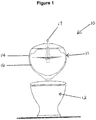
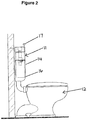
- a flush toilet 10 that has a cistern assembly 11 and a toilet bowl 12.
- the cistern assembly 11 includes a cistern housing 14, a substantially semi-circular basin 16 forming the cistern member and a lever 17 protruding from a slot (not shown) in the housing 14.
- the basin 16 is pivotally mounted to the cistern housing 14 and the lever 17 is attached to the basin 16 so that when the lever 17 is moved sideways the basin 16 will tilt relative to the cistern housing 14.
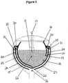
- the basin 16 forms a chamber 18 defined by the basin base wall 15.
- Water from a water supply such as mains water supply fills the chamber 18 to a predetermined volume of water.
- the volume of water is controlled by a float valve 13 positioned near the water inlet 32. The float valve 13 stops the entry of the water when a predetermined water level is reached.
- the basin 16 has two passageways 20, 21 that are located on opposite sides of the basin 16. Water is stored in the chamber 18 and can be discharged through either one of the two passageways 20, 21.
- Both passageways 20, 21 have an inner section 30 in continuous communication with an outer section 31.
- Each inner section 30 is formed by an inner side wall 23, 24 and the base wall 15 while each outer section 31 is formed by an outer side wall 26, 27 and the base wall 15.
- An inner section 30 and an outer section 31 are connected by a substantially U-shaped bend 25 to form a continuous channel.
- the internal dimensions of the inner section 30, the outer section 31 and the substantially U-shaped bend 25 are substantially the same to optimize the siphoning action through each passageway 20, 21. Water enters the passageways 20, 21 via the internal inlet 22, 19 respectively and passes out through the cistern outlet 36.
- the two passageways 20, 21 are of different lengths for discharging a different volume of water.
- the different lengths of the passageways 20, 21 are formed by inner side walls 23, 24 respectively having different lengths.
- the inner side wall 24 of the passageway 21 is about half of the length of the inner side wall 23 of passageway 20.
- the basin 16 is tilted within the cistern housing 14 using a lever 17.
- the basin 16 pivots about a horizontal axis 35 being the central axis through the centre of the basin 16 and the pivot point.
- the basin 16 can be rotated in a vertical plane about the pivot point of the basin 16.
- the lever 17 can be pivoted about 20 degrees to either the left or the right of the pivot axis 35. With reference to Figure 5 , tilting the basin 16 to the left of the pivot axis 35 performs a full flush while tilting the basin 16 to the right of the pivot axis 35 performs a half flush.
- the basin 16 is substantially semi-circular in shape having a center of gravity lower than its pivot point.
- the basin 16 can right itself returning from an inclined position to an upright position when the basin 16 is substantially emptied of water.
- Water is discharged through the passageway 20 until air enters the passageway 20 via internal inlet 22 and breaks the siphoning action.
- the length of the inner wall 23 of the passageway 20 locates the internal inlet 22 near the bottom of the chamber 18, air enters the left passageway 20 when substantially all the stored water is discharged from the chamber 18.
- the float valve 13 opens and water enters the basin 16 via the water inlet 32 to refill the basin 16 to the predetermined volume.
- the passageway 21 When the lever 17 is moved to tilt the basin 16 within the cistern housing 14 in a clockwise direction (as shown in Figure 6 ), the passageway 21 is lowered. A siphoning action is established when the passageway 21 is lowered below the water level of the stored water. Since the inner wall 24 of the passageway 21 is about half the length of the inner wall 23 of the passageway 20, air enters the passageway 21 through the higher internal inlet 19 to break the siphoning action after about half of the stored water has been discharged from the chamber 18. Water from water supply enters the basin 16 via the water inlet 32 to refill the basin 16 to the predetermined volume when the float valve 13 opens.
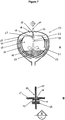
- a second embodiment of a cistern assembly 50 is similar to the cistern assembly 11 described above, except that the cistern assembly 50 has a floatable lever 52 that can rise and fall with the level, of water in the chamber 53.
- the buoyancy of the floatable lever 52 enables the floatable lever 52 to be positioned to hold the basin 55 in a tilted position to actuate discharge of water through the passageway 56 or 57.
- the floatable lever 52 has an elongate portion 58 and a buoyancy portion 59 at one end of the elongate portion 58.
- a handle portion 60 is located at the opposed end of the buoyancy portion 59.
- the buoyancy portion 59 has a dumbbell shaped cross section.
- a transverse portion in the form of a cross bar 62 is located adjacent the handle portion 60 and substantially at right angles to the elongate portion 58.
- the floatable lever 52 is attached to the front side wall 63 of the basin 55 by two member guides 64.
- the two member guides 64 are fixed to the side wall 63 of the basin 55.
- the elongate portion 58 of the floatable lever 52 is retained by the two member guides 64 but can rise and fall with the level of water in the chamber 53.
- the cistern housing 65 includes a lid 67 with a slot 68 and two guide flanges 70 on the underside of the lid 67.
- the flanges 70 are spaced apart by the slot 68.
- the two guide flanges 70 are adjacent either longitudinal side of the slot 68.
- Each guide flange 70 has a substantially arcuate and substantially concave shape with two ends 71, 72. Each of the two ends form an abutment side 71, 72 to retain the cross bar 62 in a fixed position for a short period of time and thereby hold the basin 55 in a tilted position.
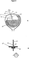
- the floatable lever 52 When there is a low level of water in the basin 55, the floatable lever 52 is positioned with the cross bar 62 below the slot 68 and the cross bar 62 is not engaged with the guide flanges 70. This is shown in Figures 7A and 7B .
- the buoyancy portion 59 causes the floatable lever 52 to rise.
- the cross bar 62 rises with the floatable lever 52 to engage the guide flanges 70.
- the floatable lever 52 is configured so that the cross bar 62 engages with the guide flanges 70 when the basin 55 is filled with water to at least half the predetermined volume of the chamber 53.
- the basin 55 is tilted by deflecting the floatable lever 52 so that the cross bar 62 moves towards one end 71 or 72 of the guide flanges 70 and engages with respective abutment side 71 or 72.
- This is shown in Figures 9A and 9B . Due to buoyancy of the floatable lever 52 and the tendency for the basin 55 to return to its initial position, the cross bar 62 is held in a fixed position against the abutment side 71 or 72.
- the floatable lever 52 is configured so that the cross bar 62 is held in a fixed position against the abutment side 71 or 72 when there is at least half the predetermined volume of water in the chamber 53. This volume of water keeps the floatable lever 52 in a raised position so that the cross bar 62 is prevented from moving beyond the abutment side 72 of the guide flange 70 (as shown in Figures 9A and 9B ). As a consequence the basin 55 is held in the tilted position to actuate discharge of water through the passageway 56.
- the position of the floatable lever 52 falls with the water level.
- the cross bar 62 drops below the guide flange 70 and therefore the abutment side 72 no longer resists the tendency for basin 55 to return to its initial position.
- the basin 55 refills with water from the water supply as described above for the cistern assembly 11, the basin 55 returns to its initial position with the floatable lever 52 in the substantially vertical position.
- the floatable lever 52 is configured to position the buoyancy portion 59 between a full flush water level and a half flush water level when the chamber 53 is filled with the predetermined volume of water.
- the full flush water level is the level of water in the basin 55 when the basin 55 is filled with the predetermined volume of water in the chamber 53.
- the half flush water, level is the level of water when the basin 55 is half filled with the predetermined volume of water. The positioning of the buoyancy position 59 relative to the half flush water level is important to enable the floatable lever 52 to move downwardly for a distance sufficient for the cross bar 62 to move below the guide flanges 70 during the operation of a half flush.
- the floatable lever 52 is moved to tilt the basin 55 within the cistern housing 65 in an anticlockwise direction to actuate a full flush (as shown in Figure 10 .).
- the floatable lever 52 is moved in a clockwise direction (not shown in the Figures).
- the steps that occur during a full flush and a half flush of the cistern assembly 50 is similar to the steps that occur during a full flush, and half flush of the cistern assembly 11 described above.
- the cistern assembly 75 includes a cistern housing 76, a basin 77 that is positioned within the cistern housing 76, a handle 78 for tilting the basin 77 relative to the cistern housing 76 and a floatable latch 79 for holding the basin 77 in a tilted position to actuate the discharge of water from basin 77 through passageway 93 or 94.
- the cistern housing 76 has a lid 82 and a housing base 83.
- the housing base 83 has two housing pivot portions 85, 87 that protrude from opposed inner sidewalls 90, 92, respectively, of the housing base 83.
- the basin 77 is positioned within the housing base 83 and pivotally mounted to the cistern housing 76 via the two housing pivot portions 85, 87.
- the housing base 83 has an arcuate slot 86 for the handle 78 to pass through when the basin 77 is mounted within the housing base 83.
- the lid 82 has an inner guide flange 80 with two abutment sides 81, 84.
- the lid 82 is positioned over the housing base 83 so that the floatable latch 79 can engage with the inner guide flange 80 when there is at least half the predetermined volume of water in the chamber 104 of the basin 77.
- the basin 77 is similar to the basin 16 of the cistern assembly 11 described above except that the basin 77 is tilted relative to the cistern housing 76 by the handle 78 that is fixed to a side wall 91 of the basin 77.
- The, basin 77 has two basin pivot portions 88, 89 that protrude from opposed side walls 91, 95 respectively, of the basin 77.
- the two basin pivot portions 88, 89 engage housing pivot portions 85, 87 respectively, of the housing base 83.
- the basin 77 is pivotally mounted within the cistern housing 76 by the mounting of the basin pivot portions 88, 89 with the housing pivot portions 85, 87
- the basin 77 has two passageways 93, 94 that are of different lengths. A different volume of water is discharged from the basin 77 depending on whether the basin 77 is tilted towards the left-hand side or the right-hand side of the cistern housing 76.
- the floatable latch 79 has an elongate portion 96 and a buoyancy portion 97.
- the buoyancy portion 97 is located a bottom end of the elongate portion 96 while a follower wheel 98 is located at a top end of the elongate portion 96.
- the floatable latch 79 is positioned by two member guides 102 to retain the floatable latch 79 to the side wall 91 of the basin 77.
- the two member guides 102 are fixed to the side wall 91 of the basin 77 and retain the elongate portion 96 of the floatable latch 79 whilst allowing the floatable latch 79 to rise and fall with the level of water in the basin 77.
- the floatable latch 79 is not integrally formed with the handle 78 but is operatively associated with the handle 78, so that when the handle moves laterally the float latch 79 cooperatively moves laterally, The float latch 79 can rise and fall independent of the handle 78. Because the floatable latch 79 is retained by the member guides 102 to the side wall 91 of the basin 77, the basin and the floatable latch 79 tilt simultaneously when the handle 78 is moved and tilts the basin 77.
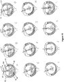
- the handle 78 In order to perform a full flush, the handle 78 is used to tilt the basin 77 towards the left-hand side of the cistern housing 76. The steps that occur during a full flush are shown in Figure 14 . In order to perform a half flush, the handle 78 is pushed to tilt the basin 77 towards the right-hand side of the cistern housing 76.
- the floatable latch 79 has buoyancy that enables the follower wheel 98 to travel along the guide flange 80 and be held in a fixed position against one of the abutment side 84.
- the floatable latch 79 is maintained abutted against the abutment side 84 when there is about half or more of the predetermined volume of water in the chamber 104 of the basin 77. This volume of water keeps the floatable latch 79 in a raised position to resist the tendency for the basin 77 to return to its initial position by preventing the follower wheel 98 from moving beyond the abutment side 84 of the guide flange 80 (as shown in Figures 14 (D) and (E) ). As a consequence the basin 77 is held in a tilted position to actuate discharge of water through the passageway 94.
- the position of the floatable latch 79 falls with the water level.
- the floatable latch 79 is in a lowered position and the floatable latch 79 no longer abuts the abutment side 84.
- the floatable latch 79 then moves towards a substantially vertical position while water continues to discharge through the passageway 94. Discharge of water stops when air enters and breaks the siphoning action in passageway 94.
- the chamber 104 is then refilled with water from the water inlet 106.
- the volume of water in the chamber 104 is controlled by a float valve 105 positioned near the water inlet 106.
- the float valve 105 stops entry of water into the chamber 104 when the predetermined water level is reached.
- the cistern assembly 110 is similar to the cistern assembly 75 except that the cistern assembly 110 has a basin 112 that is capable of discharging four different volumes of water.
- the basin 112 has a right-hand passageway 117 with an inner side wall 113.
- the inner side wall 113 has three apertures 114, 119, 120.
- the apertures 114, 119, 120 can be closed with the positioning of a removable seal 115.
- apertures 119 and 120 are closed by seals 115 while the aperture 114 remains open.
- Each of the apertures 114, 119, 120 can be plugged with a removable seal 115 to alter the effective length of the passageway 117.
- the effective length of the passageway 117 increases as apertures 114, 119 and 120 are successively plugged.
- the effective length of the passageway 117 in turn determines the volume of water that is discharged from the chamber 116.
- the three spaced apart apertures in the inner side wall 113 provides a person with the option of selecting one of three different volumes of water to be discharged. If all apertures are plugged then there is a fourth option of a full volume flush. With the aperture 114 open, a lower volume of water will be discharged compared with the volume of water discharged when only aperture 120 is open. As water is discharged and air passes though the open aperture, the siphoning action is broken and water is not drawn into the passageway 117.
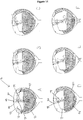
- Figure 16 shows the steps during a partial flush with aperture 114 open.
- the upper aperture 114 can be plugged and the middle aperture 119 or lower aperture 120 is unplugged to increase the volume of water discharged through the passageway 117.
- the cistern assembly 110 operates in a way similar to the cistern assembly 75 described above.
- Figure 17 shows the steps during a full flush.
- An advantage of the preferred embodiment of the cistern assembly is the provision of a simple flush arrangement without separate moving parts for a flush toilet.
- a further advantage of the preferred embodiment of the cistern assembly is that the simplicity of the design reduces the number of parts in the assembly and therefore reduces the amount of maintenance required during the lifetime of the cistern assembly.
- Another advantage of the preferred embodiment of the cistern assembly is the elimination of the need for a valve to effectively seal the cistern outlet thereby avoiding the problem of water loss and consequences thereof if the seal is ineffective.
- Another advantage of the preferred embodiment of the cistern assembly is the provision of a choice of two volumes of water for flushing the toilet bowl.
- a further advantage of the preferred embodiment of the cistern assembly is the provision of a floatable latch that can be positioned to hold the cistern member in a tilted position to actuate discharge of water through the passageway.
Landscapes
- Health & Medical Sciences (AREA)
- Life Sciences & Earth Sciences (AREA)
- Engineering & Computer Science (AREA)
- Hydrology & Water Resources (AREA)
- Public Health (AREA)
- Water Supply & Treatment (AREA)
- Sanitary Device For Flush Toilet (AREA)
Claims (17)
- Spülkastenanordnung (11) für eine Wasserspültoilette (10), enthaltend:ein Spülkastengehäuse (14) mit einem Spülkastendeckel und einer Spülkastenbasis;ein Spülkastenglied (16), das schwenkbar innerhalb des Spülkastengehäuses angebracht ist, wobei das Spülkastenglied eine Basiswand (15) aufweist, die eine Kammer (18) zum Speichern von Wasser und einen Durchgang (20, 21) zum Ablassen von Wasser aus der Kammer ausbildet, wobei der Durchgang einen inneren Einlass (19, 22) und einen Spülkastenauslass (36) aufweist und zum Abziehen von Wasser durch den Durchgang geformt ist; undein Stellglied (17), das dem Spülkastenglied (16) zugeordnet ist, zum Schwenken des Spülkastenglieds bezüglich des Spülkastengehäuses (14), wobei das Stellglied (17) das Spülkastenglied zum Auslösen des Ablassens von Wasser durch den Durchgang (20, 21) kippen kann, wobei, wenn das Spülkastenglied (16) geschwenkt und der Durchgang (20, 21) unter den Wasserpegel des gespeicherten Wassers der Kammer (18) bewegt wird, das Wasser durch den Durchgang (20, 21) zum Spülkastenauslass (36) gezogen wird, bis Luft innerhalb der Kammer in den Durchgang eintritt, wodurch verhindert ist, dass weiteres Wasser in den Durchgang gezogen wird;dadurch gekennzeichnet, dass das Spülkastenglied (16) einen im Wesentlichen halbkreisförmigen Querschnitt aufweist und die Basiswand (15) im Wesentlichen konkav in der Form ist, wobei das Spülkastenglied (16) einen Schwerpunkt aufweist, der niedriger als sein Schwenkpunkt liegt, wodurch ermöglicht ist, dass das Spülkastenglied selbstaufrichtend ist und aus einer geneigten Position in eine aufrechte Position zurückkehrt, wenn das Spülkastenglied (16) im Wesentlichen von Wasser entleert ist.
- Spülkastenanordnung nach Anspruch 1, wobei der Durchgang (20, 21) eine erste Sektion (30), die innerhalb der Kammer (18) ausgebildet ist, und eine zweite Sektion (31) aufweist, die außerhalb der Kammer ausgebildet ist, wobei die erste Sektion und die zweite Sektion fortlaufende Fluidverbindung zwischen dem inneren Einlass (19, 22) des Durchgangs und dem Spülkastenauslass (36) ermöglichen, wobei die erste Sektion durch eine innere Seitenwand (23, 24) und eine Basiswand (15) ausgebildet ist und die zweite Sektion durch eine äußere Seitenwand (26, 27) und die Basiswand (15) ausgebildet ist.
- Spülkastenanordnung nach Anspruch 2, wobei die erste Sektion und die zweite Sektion durch einen im Wesentlichen U-förmigen Abschnitt (25) verbunden sind; wobei die erste Sektion (30), der im Wesentlichen U-förmige Abschnitt (25) und die zweite Sektion (31) Innenabmessungen aufweisen, die im Wesentlichen dieselben sind.
- Spülkastenanordnung nach einem der Ansprüche 2 oder 3, wobei die Länge der inneren Seitenwand (23, 24) die Länge des Durchgangs (20, 21) und das Volumen von Wasser, das abgelassen werden soll, bestimmt.
- Spülkastenanordnung nach einem der Ansprüche 2 bis 4, wobei die innere Seitenwand (23, 24) eine Öffnung (114, 119, 120) zwischen der Kammer und dem Durchgang (20, 21) aufweist, wodurch das Volumen von Wasser, das abgelassen werden soll, begrenzt wird.
- Spülkastenanordnung nach einem der Ansprüche 2 bis 4, wobei die innere Seitenwand (23, 24) mehrere Öffnungen (114, 119, 120) aufweist, wobei eine der Öffnungen offen ist, während die restlichen Öffnungen der mehreren Öffnungen mit einer Dichtung (115) verschlossen sind.
- Spülkastenanordnung nach einem der vorhergehenden Ansprüche, wobei das Spülkastenglied (16) mehrere Durchgänge (20, 21) aufweist, um zu ermöglichen, dass verschiedene Volumen von gespeichertem Wasser aus der Kammer abgelassen werden.
- Spülkastenanordnung nach einem der vorhergehenden Ansprüche, wobei das Spülkastenglied (16) zwei Durchgänge (20, 21) aufweist, um die Wahl zwischen zwei verschiedenen von gespeichertem Wasser, das abgelassen werden soll, zu ermöglichen, wobei die innere Seitenwand (23, 24) von jedem der Durchgänge eine unterschiedliche Länge aufweist.
- Spülkastenanordnung nach Anspruch 8, wobei der erste Durchgang (20) ermöglicht, dass im Wesentlichen die Gesamtheit des vorbestimmten Volumens von Wasser aus der Kammer abgelassen wird, und wobei der zweite Durchgang (21) ermöglicht, dass ungefähr die Hälfte des vorbestimmten Volumens von Wasser aus der Kammer abgelassen wird.
- Spülkastenanordnung nach einem der vorhergehenden Ansprüche, wobei das Spülkastenglied (16) schwenkbar am Spülkastengehäuse (14) angebracht ist und um eine horizontale Achse schwenkbar ist, die im Wesentlichen in der Mitte des Spülkastenglieds (16) angeordnet ist.
- Spülkastenanordnung nach einem der vorhergehenden Ansprüche, wobei das Stellglied (17) einen Hebel enthält, der schwenkbar am Spülkastengehäuse (14) angebracht ist und mit dem Spülkastenglied (16) schwenkt.
- Spülkastenanordnung nach einem der Ansprüche 1 bis 10, wobei das Stellglied (17) einen Hebelabschnitt (60) und einen Schwimmabschnitt (59) als einstückiges oder zusammengebautes Glied enthält, wobei der Hebelabschnitt einen Querstift zum Gebrauch als Sperre zum Angrenzen an die Oberfläche einer Sperrenführung enthält, wobei der Hebelabschnitt (60) durch eine gestreckte Deckelöffnung (68) verläuft und als Griff zum Kippen des Spülkastenglieds dient.
- Spülkastenanordnung nach Anspruch 12, wobei der einstückige oder zusammengebaute Hebelabschnitt (60) und der Schwimmabschnitt (59) durch eine oder mehr Gliedführungen (64) erfasst sind, die an der Seitenwand des Spülkastenglieds (16) befestigt sind, sodass er sich gemäß dem Wasserpegel innerhalb des Spülkastenglieds nach oben und nach unten bewegen kann.
- Spülkastenanordnung nach einem der Ansprüche 1 bis 10, wobei das Stellglied (17) einen Griff (78) zum Bewegen des Spülkastenglieds (16) bezüglich des Spülkastengehäuses (14) und ein schwimmfähiges Glied (79) zum Sperren des Spülkastenglieds in der Kippposition enthält.
- Spülkastenanordnung nach Anspruch 14, wobei das schwimmfähige Glied (79) einen gestreckten Abschnitt (96) und einen Auftriebsabschnitt (97) enthält, wobei der Auftriebsabschnitt nahe einem Ende des schwimmfähigen Glieds (79) angeordnet ist, und wobei der Auftriebsabschnitt genügenden Auftrieb aufweist, um zu bewirken, dass sich das schwimmfähige Glied mit dem Pegel des Wassers im Spülkastenglied (16) nach oben und nach unten bewegt.
- Spülkastenanordnung nach Anspruch 14, wobei das schwimmfähige Glied (79) in der Mitte des Spülkastenglieds positionierbar ist, und wobei das schwimmfähige Glied durch eine oder mehr voneinander beabstandete Gliedführungen (102) erfasst ist, die an einer Seitenwand des Spülkastenglieds (16) angebracht sind, sodass das schwimmfähige Glied mit dem Pegel des Wassers im Spülkastenglied steigen und sinken kann.
- Spülkastenanordnung nach Anspruch 16, wobei der gestreckte Abschnitt (96) eine Sperre aufweist, die an einem Ende zur Ineingriffnahme einer Sperrenführung ausgebildet ist.
Applications Claiming Priority (2)
| Application Number | Priority Date | Filing Date | Title |
|---|---|---|---|
| AU2007905179A AU2007905179A0 (en) | 2007-09-24 | A cistern assembly | |
| PCT/AU2008/001401 WO2009039561A1 (en) | 2007-09-24 | 2008-09-19 | A cistern assembly |
Publications (3)
| Publication Number | Publication Date |
|---|---|
| EP2205801A1 EP2205801A1 (de) | 2010-07-14 |
| EP2205801A4 EP2205801A4 (de) | 2015-11-18 |
| EP2205801B1 true EP2205801B1 (de) | 2018-07-18 |
Family
ID=40510657
Family Applications (1)
| Application Number | Title | Priority Date | Filing Date |
|---|---|---|---|
| EP08800036.9A Not-in-force EP2205801B1 (de) | 2007-09-24 | 2008-09-19 | Spülkastenanordnung |
Country Status (6)
| Country | Link |
|---|---|
| US (1) | US8387173B2 (de) |
| EP (1) | EP2205801B1 (de) |
| CN (1) | CN101849070B (de) |
| AU (1) | AU2008303051B2 (de) |
| WO (1) | WO2009039561A1 (de) |
| ZA (1) | ZA201002776B (de) |
Families Citing this family (6)
| Publication number | Priority date | Publication date | Assignee | Title |
|---|---|---|---|---|
| JP5850603B2 (ja) * | 2010-07-23 | 2016-02-03 | メタフラッシュ ピーティワイ リミテッドMetaflush Pty Ltd | 水槽組立体 |
| FR2967427B1 (fr) * | 2010-11-11 | 2012-12-21 | Norberto Neves | Dispositif de distribution de produit desodorisant pour dispositif de chasse d'eau de cuvette de wc |
| HK1198449A1 (zh) * | 2011-07-25 | 2015-04-24 | Metaflush Pty Ltd | 水箱组件 |
| CN107532415B (zh) * | 2015-03-12 | 2020-06-02 | 芙洛玛斯特公司 | 抗虹吸引流器 |
| CN216041559U (zh) * | 2021-08-21 | 2022-03-15 | 中山市美图塑料工业有限公司 | 一种用于调节隐藏式水箱用水量的调节装置 |
| US20250146260A1 (en) * | 2023-11-06 | 2025-05-08 | Fluidmaster, Inc. | Cistern system, apparatus and method |
Citations (1)
| Publication number | Priority date | Publication date | Assignee | Title |
|---|---|---|---|---|
| DE19504783A1 (de) * | 1995-02-14 | 1996-08-22 | Heribert F Dr Ing Broicher | Vorrichtung zur Wasserspülung von Toiletten |
Family Cites Families (10)
| Publication number | Priority date | Publication date | Assignee | Title |
|---|---|---|---|---|
| US2010386A (en) * | 1934-04-28 | 1935-08-06 | Robert P Wilson | Flush tank |
| IS3932A (is) * | 1991-10-16 | 1993-04-17 | Dallah Water Saving | Loka- eða ventilútbúnaður til að stjórna vatnshæðeða -magni og vatnskassi fyrir salerni |
| KR20030022274A (ko) * | 2000-07-11 | 2003-03-15 | 아토 비.브이. | 히드록실화 콜라겐 유사 화합물의 제조 방법 |
| US6317899B1 (en) | 2000-08-17 | 2001-11-20 | Niagara Conservation Corporation | Dual flush toilet |
| AUPR695801A0 (en) * | 2001-08-10 | 2001-09-06 | Caroma Industries Limited | An ultra-low volume gravity flushing toilet |
| US6611967B1 (en) * | 2002-06-06 | 2003-09-02 | Flapperless, Inc. | Dump bucket toilet with controlled discharge and return |
| CN1492112A (zh) | 2002-10-24 | 2004-04-28 | 史继龄 | 水箱倾翻式抽水马桶冲水装置 |
| GB2402136B (en) * | 2003-05-24 | 2006-05-10 | Steadman William D | Toilet flushing arrangement |
| DE10324856A1 (de) | 2003-06-02 | 2004-12-30 | Johannes Schulte | Spülkasten für eine Toilettenspülung |
| CN1932175A (zh) * | 2006-10-12 | 2007-03-21 | 肖新凯 | 不漏水、按需用水的节水水箱 |
-
2008
- 2008-09-19 EP EP08800036.9A patent/EP2205801B1/de not_active Not-in-force
- 2008-09-19 US US12/679,444 patent/US8387173B2/en not_active Expired - Fee Related
- 2008-09-19 CN CN200880114848XA patent/CN101849070B/zh not_active Expired - Fee Related
- 2008-09-19 WO PCT/AU2008/001401 patent/WO2009039561A1/en not_active Ceased
- 2008-09-19 AU AU2008303051A patent/AU2008303051B2/en not_active Ceased
-
2010
- 2010-04-20 ZA ZA2010/02776A patent/ZA201002776B/en unknown
Patent Citations (1)
| Publication number | Priority date | Publication date | Assignee | Title |
|---|---|---|---|---|
| DE19504783A1 (de) * | 1995-02-14 | 1996-08-22 | Heribert F Dr Ing Broicher | Vorrichtung zur Wasserspülung von Toiletten |
Also Published As
| Publication number | Publication date |
|---|---|
| WO2009039561A1 (en) | 2009-04-02 |
| US8387173B2 (en) | 2013-03-05 |
| US20100251470A1 (en) | 2010-10-07 |
| HK1148563A1 (zh) | 2011-09-09 |
| AU2008303051B2 (en) | 2015-01-29 |
| CN101849070A (zh) | 2010-09-29 |
| CN101849070B (zh) | 2011-12-14 |
| AU2008303051A1 (en) | 2009-04-02 |
| EP2205801A4 (de) | 2015-11-18 |
| EP2205801A1 (de) | 2010-07-14 |
| ZA201002776B (en) | 2010-12-29 |
Similar Documents
| Publication | Publication Date | Title |
|---|---|---|
| US8387173B2 (en) | Cistern assembly | |
| EP3268646B1 (de) | Vakuumbetriebenes ventil | |
| US6944890B1 (en) | Automatic cleaning assembly for a toilet bowl | |
| US9062795B2 (en) | Water saver fill valve and assembly | |
| US8387652B2 (en) | Water saver fill valve and assembly | |
| DK2406436T3 (en) | Odor lock for a waterless urinal | |
| US10221553B2 (en) | Toilet flush valve assemblies | |
| EP2321476B1 (de) | Ablassvorrichtung für spülkasten mit beweglichem heber | |
| US20080078454A1 (en) | Water saver fill valve and assembly | |
| US5926860A (en) | Low profile vacuum toilet | |
| US8117687B2 (en) | Diverter valve with minimum bias forces | |
| HK1148563B (en) | A cistern assembly | |
| AP8A (en) | Lavatory cistern. | |
| US5274855A (en) | Siphon flushing mechanism and method | |
| CA2557956C (en) | Dual flush system for toilet | |
| US8296871B2 (en) | Toilet water tank refilling system | |
| JP6890566B2 (ja) | 便器洗浄用給水装置 | |
| CN101389814B (zh) | 排放两种不同冲水量的虹吸管 | |
| EP3363957A1 (de) | Ein- und ablaufgarnitur für einen spülkasten |
Legal Events
| Date | Code | Title | Description |
|---|---|---|---|
| PUAI | Public reference made under article 153(3) epc to a published international application that has entered the european phase |
Free format text: ORIGINAL CODE: 0009012 |
|
| 17P | Request for examination filed |
Effective date: 20100421 |
|
| AK | Designated contracting states |
Kind code of ref document: A1 Designated state(s): AT BE BG CH CY CZ DE DK EE ES FI FR GB GR HR HU IE IS IT LI LT LU LV MC MT NL NO PL PT RO SE SI SK TR |
|
| AX | Request for extension of the european patent |
Extension state: AL BA MK RS |
|
| RAP1 | Party data changed (applicant data changed or rights of an application transferred) |
Owner name: METAFLUSH PTY LTD |
|
| DAX | Request for extension of the european patent (deleted) | ||
| RA4 | Supplementary search report drawn up and despatched (corrected) |
Effective date: 20151016 |
|
| RIC1 | Information provided on ipc code assigned before grant |
Ipc: E03D 11/00 20060101ALI20151012BHEP Ipc: E03D 1/14 20060101ALI20151012BHEP Ipc: E03D 1/20 20060101AFI20151012BHEP |
|
| STAA | Information on the status of an ep patent application or granted ep patent |
Free format text: STATUS: EXAMINATION IS IN PROGRESS |
|
| 17Q | First examination report despatched |
Effective date: 20161027 |
|
| GRAP | Despatch of communication of intention to grant a patent |
Free format text: ORIGINAL CODE: EPIDOSNIGR1 |
|
| STAA | Information on the status of an ep patent application or granted ep patent |
Free format text: STATUS: GRANT OF PATENT IS INTENDED |
|
| INTG | Intention to grant announced |
Effective date: 20170925 |
|
| GRAJ | Information related to disapproval of communication of intention to grant by the applicant or resumption of examination proceedings by the epo deleted |
Free format text: ORIGINAL CODE: EPIDOSDIGR1 |
|
| STAA | Information on the status of an ep patent application or granted ep patent |
Free format text: STATUS: EXAMINATION IS IN PROGRESS |
|
| GRAP | Despatch of communication of intention to grant a patent |
Free format text: ORIGINAL CODE: EPIDOSNIGR1 |
|
| STAA | Information on the status of an ep patent application or granted ep patent |
Free format text: STATUS: GRANT OF PATENT IS INTENDED |
|
| INTC | Intention to grant announced (deleted) | ||
| INTG | Intention to grant announced |
Effective date: 20180212 |
|
| GRAS | Grant fee paid |
Free format text: ORIGINAL CODE: EPIDOSNIGR3 |
|
| GRAA | (expected) grant |
Free format text: ORIGINAL CODE: 0009210 |
|
| STAA | Information on the status of an ep patent application or granted ep patent |
Free format text: STATUS: THE PATENT HAS BEEN GRANTED |
|
| AK | Designated contracting states |
Kind code of ref document: B1 Designated state(s): AT BE BG CH CY CZ DE DK EE ES FI FR GB GR HR HU IE IS IT LI LT LU LV MC MT NL NO PL PT RO SE SI SK TR |
|
| REG | Reference to a national code |
Ref country code: GB Ref legal event code: FG4D |
|
| REG | Reference to a national code |
Ref country code: CH Ref legal event code: EP |
|
| REG | Reference to a national code |
Ref country code: IE Ref legal event code: FG4D |
|
| REG | Reference to a national code |
Ref country code: AT Ref legal event code: REF Ref document number: 1019518 Country of ref document: AT Kind code of ref document: T Effective date: 20180815 |
|
| REG | Reference to a national code |
Ref country code: DE Ref legal event code: R096 Ref document number: 602008056071 Country of ref document: DE |
|
| REG | Reference to a national code |
Ref country code: FR Ref legal event code: PLFP Year of fee payment: 11 |
|
| REG | Reference to a national code |
Ref country code: NL Ref legal event code: MP Effective date: 20180718 |
|
| REG | Reference to a national code |
Ref country code: LT Ref legal event code: MG4D |
|
| REG | Reference to a national code |
Ref country code: AT Ref legal event code: MK05 Ref document number: 1019518 Country of ref document: AT Kind code of ref document: T Effective date: 20180718 |
|
| PG25 | Lapsed in a contracting state [announced via postgrant information from national office to epo] |
Ref country code: NL Free format text: LAPSE BECAUSE OF FAILURE TO SUBMIT A TRANSLATION OF THE DESCRIPTION OR TO PAY THE FEE WITHIN THE PRESCRIBED TIME-LIMIT Effective date: 20180718 |
|
| PG25 | Lapsed in a contracting state [announced via postgrant information from national office to epo] |
Ref country code: PL Free format text: LAPSE BECAUSE OF FAILURE TO SUBMIT A TRANSLATION OF THE DESCRIPTION OR TO PAY THE FEE WITHIN THE PRESCRIBED TIME-LIMIT Effective date: 20180718 Ref country code: IS Free format text: LAPSE BECAUSE OF FAILURE TO SUBMIT A TRANSLATION OF THE DESCRIPTION OR TO PAY THE FEE WITHIN THE PRESCRIBED TIME-LIMIT Effective date: 20181118 Ref country code: AT Free format text: LAPSE BECAUSE OF FAILURE TO SUBMIT A TRANSLATION OF THE DESCRIPTION OR TO PAY THE FEE WITHIN THE PRESCRIBED TIME-LIMIT Effective date: 20180718 Ref country code: BG Free format text: LAPSE BECAUSE OF FAILURE TO SUBMIT A TRANSLATION OF THE DESCRIPTION OR TO PAY THE FEE WITHIN THE PRESCRIBED TIME-LIMIT Effective date: 20181018 Ref country code: LT Free format text: LAPSE BECAUSE OF FAILURE TO SUBMIT A TRANSLATION OF THE DESCRIPTION OR TO PAY THE FEE WITHIN THE PRESCRIBED TIME-LIMIT Effective date: 20180718 Ref country code: GR Free format text: LAPSE BECAUSE OF FAILURE TO SUBMIT A TRANSLATION OF THE DESCRIPTION OR TO PAY THE FEE WITHIN THE PRESCRIBED TIME-LIMIT Effective date: 20181019 Ref country code: SE Free format text: LAPSE BECAUSE OF FAILURE TO SUBMIT A TRANSLATION OF THE DESCRIPTION OR TO PAY THE FEE WITHIN THE PRESCRIBED TIME-LIMIT Effective date: 20180718 Ref country code: NO Free format text: LAPSE BECAUSE OF FAILURE TO SUBMIT A TRANSLATION OF THE DESCRIPTION OR TO PAY THE FEE WITHIN THE PRESCRIBED TIME-LIMIT Effective date: 20181018 Ref country code: FI Free format text: LAPSE BECAUSE OF FAILURE TO SUBMIT A TRANSLATION OF THE DESCRIPTION OR TO PAY THE FEE WITHIN THE PRESCRIBED TIME-LIMIT Effective date: 20180718 |
|
| PG25 | Lapsed in a contracting state [announced via postgrant information from national office to epo] |
Ref country code: HR Free format text: LAPSE BECAUSE OF FAILURE TO SUBMIT A TRANSLATION OF THE DESCRIPTION OR TO PAY THE FEE WITHIN THE PRESCRIBED TIME-LIMIT Effective date: 20180718 Ref country code: ES Free format text: LAPSE BECAUSE OF FAILURE TO SUBMIT A TRANSLATION OF THE DESCRIPTION OR TO PAY THE FEE WITHIN THE PRESCRIBED TIME-LIMIT Effective date: 20180718 Ref country code: LV Free format text: LAPSE BECAUSE OF FAILURE TO SUBMIT A TRANSLATION OF THE DESCRIPTION OR TO PAY THE FEE WITHIN THE PRESCRIBED TIME-LIMIT Effective date: 20180718 |
|
| REG | Reference to a national code |
Ref country code: DE Ref legal event code: R097 Ref document number: 602008056071 Country of ref document: DE |
|
| PG25 | Lapsed in a contracting state [announced via postgrant information from national office to epo] |
Ref country code: RO Free format text: LAPSE BECAUSE OF FAILURE TO SUBMIT A TRANSLATION OF THE DESCRIPTION OR TO PAY THE FEE WITHIN THE PRESCRIBED TIME-LIMIT Effective date: 20180718 Ref country code: CZ Free format text: LAPSE BECAUSE OF FAILURE TO SUBMIT A TRANSLATION OF THE DESCRIPTION OR TO PAY THE FEE WITHIN THE PRESCRIBED TIME-LIMIT Effective date: 20180718 Ref country code: EE Free format text: LAPSE BECAUSE OF FAILURE TO SUBMIT A TRANSLATION OF THE DESCRIPTION OR TO PAY THE FEE WITHIN THE PRESCRIBED TIME-LIMIT Effective date: 20180718 Ref country code: MC Free format text: LAPSE BECAUSE OF FAILURE TO SUBMIT A TRANSLATION OF THE DESCRIPTION OR TO PAY THE FEE WITHIN THE PRESCRIBED TIME-LIMIT Effective date: 20180718 |
|
| REG | Reference to a national code |
Ref country code: CH Ref legal event code: PL |
|
| PLBE | No opposition filed within time limit |
Free format text: ORIGINAL CODE: 0009261 |
|
| STAA | Information on the status of an ep patent application or granted ep patent |
Free format text: STATUS: NO OPPOSITION FILED WITHIN TIME LIMIT |
|
| PG25 | Lapsed in a contracting state [announced via postgrant information from national office to epo] |
Ref country code: SK Free format text: LAPSE BECAUSE OF FAILURE TO SUBMIT A TRANSLATION OF THE DESCRIPTION OR TO PAY THE FEE WITHIN THE PRESCRIBED TIME-LIMIT Effective date: 20180718 Ref country code: DK Free format text: LAPSE BECAUSE OF FAILURE TO SUBMIT A TRANSLATION OF THE DESCRIPTION OR TO PAY THE FEE WITHIN THE PRESCRIBED TIME-LIMIT Effective date: 20180718 |
|
| REG | Reference to a national code |
Ref country code: BE Ref legal event code: MM Effective date: 20180930 |
|
| 26N | No opposition filed |
Effective date: 20190423 |
|
| REG | Reference to a national code |
Ref country code: IE Ref legal event code: MM4A |
|
| PG25 | Lapsed in a contracting state [announced via postgrant information from national office to epo] |
Ref country code: LU Free format text: LAPSE BECAUSE OF NON-PAYMENT OF DUE FEES Effective date: 20180919 |
|
| PG25 | Lapsed in a contracting state [announced via postgrant information from national office to epo] |
Ref country code: IE Free format text: LAPSE BECAUSE OF NON-PAYMENT OF DUE FEES Effective date: 20180919 |
|
| PG25 | Lapsed in a contracting state [announced via postgrant information from national office to epo] |
Ref country code: CH Free format text: LAPSE BECAUSE OF NON-PAYMENT OF DUE FEES Effective date: 20180930 Ref country code: BE Free format text: LAPSE BECAUSE OF NON-PAYMENT OF DUE FEES Effective date: 20180930 Ref country code: SI Free format text: LAPSE BECAUSE OF FAILURE TO SUBMIT A TRANSLATION OF THE DESCRIPTION OR TO PAY THE FEE WITHIN THE PRESCRIBED TIME-LIMIT Effective date: 20180718 Ref country code: LI Free format text: LAPSE BECAUSE OF NON-PAYMENT OF DUE FEES Effective date: 20180930 |
|
| PGFP | Annual fee paid to national office [announced via postgrant information from national office to epo] |
Ref country code: DE Payment date: 20190918 Year of fee payment: 12 Ref country code: IT Payment date: 20190925 Year of fee payment: 12 Ref country code: FR Payment date: 20190927 Year of fee payment: 12 |
|
| PG25 | Lapsed in a contracting state [announced via postgrant information from national office to epo] |
Ref country code: MT Free format text: LAPSE BECAUSE OF NON-PAYMENT OF DUE FEES Effective date: 20180919 |
|
| PG25 | Lapsed in a contracting state [announced via postgrant information from national office to epo] |
Ref country code: TR Free format text: LAPSE BECAUSE OF FAILURE TO SUBMIT A TRANSLATION OF THE DESCRIPTION OR TO PAY THE FEE WITHIN THE PRESCRIBED TIME-LIMIT Effective date: 20180718 |
|
| PG25 | Lapsed in a contracting state [announced via postgrant information from national office to epo] |
Ref country code: PT Free format text: LAPSE BECAUSE OF FAILURE TO SUBMIT A TRANSLATION OF THE DESCRIPTION OR TO PAY THE FEE WITHIN THE PRESCRIBED TIME-LIMIT Effective date: 20180718 Ref country code: HU Free format text: LAPSE BECAUSE OF FAILURE TO SUBMIT A TRANSLATION OF THE DESCRIPTION OR TO PAY THE FEE WITHIN THE PRESCRIBED TIME-LIMIT; INVALID AB INITIO Effective date: 20080919 |
|
| PG25 | Lapsed in a contracting state [announced via postgrant information from national office to epo] |
Ref country code: CY Free format text: LAPSE BECAUSE OF FAILURE TO SUBMIT A TRANSLATION OF THE DESCRIPTION OR TO PAY THE FEE WITHIN THE PRESCRIBED TIME-LIMIT Effective date: 20180718 |
|
| REG | Reference to a national code |
Ref country code: DE Ref legal event code: R119 Ref document number: 602008056071 Country of ref document: DE |
|
| PG25 | Lapsed in a contracting state [announced via postgrant information from national office to epo] |
Ref country code: FR Free format text: LAPSE BECAUSE OF NON-PAYMENT OF DUE FEES Effective date: 20200930 Ref country code: DE Free format text: LAPSE BECAUSE OF NON-PAYMENT OF DUE FEES Effective date: 20210401 |
|
| PG25 | Lapsed in a contracting state [announced via postgrant information from national office to epo] |
Ref country code: IT Free format text: LAPSE BECAUSE OF NON-PAYMENT OF DUE FEES Effective date: 20200919 |
|
| PGFP | Annual fee paid to national office [announced via postgrant information from national office to epo] |
Ref country code: GB Payment date: 20211129 Year of fee payment: 14 |
|
| GBPC | Gb: european patent ceased through non-payment of renewal fee |
Effective date: 20220919 |
|
| PG25 | Lapsed in a contracting state [announced via postgrant information from national office to epo] |
Ref country code: GB Free format text: LAPSE BECAUSE OF NON-PAYMENT OF DUE FEES Effective date: 20220919 |