EP2202441B1 - Raccord pour la connexion des tuyaux - Google Patents
Raccord pour la connexion des tuyaux Download PDFInfo
- Publication number
- EP2202441B1 EP2202441B1 EP09180483.1A EP09180483A EP2202441B1 EP 2202441 B1 EP2202441 B1 EP 2202441B1 EP 09180483 A EP09180483 A EP 09180483A EP 2202441 B1 EP2202441 B1 EP 2202441B1
- Authority
- EP
- European Patent Office
- Prior art keywords
- tubular element
- end portion
- sleeve
- pipe
- mouth
- Prior art date
- Legal status (The legal status is an assumption and is not a legal conclusion. Google has not performed a legal analysis and makes no representation as to the accuracy of the status listed.)
- Not-in-force
Links
- 238000010438 heat treatment Methods 0.000 claims description 7
- 238000004378 air conditioning Methods 0.000 claims description 6
- 239000000463 material Substances 0.000 description 4
- XLYOFNOQVPJJNP-UHFFFAOYSA-N water Substances O XLYOFNOQVPJJNP-UHFFFAOYSA-N 0.000 description 4
- 239000007788 liquid Substances 0.000 description 3
- 239000011810 insulating material Substances 0.000 description 2
- 239000002184 metal Substances 0.000 description 2
- 238000007789 sealing Methods 0.000 description 2
- 230000000295 complement effect Effects 0.000 description 1
- 230000006835 compression Effects 0.000 description 1
- 238000007906 compression Methods 0.000 description 1
- 238000001816 cooling Methods 0.000 description 1
- 229920003020 cross-linked polyethylene Polymers 0.000 description 1
- 239000004703 cross-linked polyethylene Substances 0.000 description 1
- 238000000605 extraction Methods 0.000 description 1
- 238000003780 insertion Methods 0.000 description 1
- 230000037431 insertion Effects 0.000 description 1
- 239000004033 plastic Substances 0.000 description 1
- 229920003023 plastic Polymers 0.000 description 1
- 239000002990 reinforced plastic Substances 0.000 description 1
- 238000003466 welding Methods 0.000 description 1
Images


Classifications
-
- F—MECHANICAL ENGINEERING; LIGHTING; HEATING; WEAPONS; BLASTING
- F16—ENGINEERING ELEMENTS AND UNITS; GENERAL MEASURES FOR PRODUCING AND MAINTAINING EFFECTIVE FUNCTIONING OF MACHINES OR INSTALLATIONS; THERMAL INSULATION IN GENERAL
- F16L—PIPES; JOINTS OR FITTINGS FOR PIPES; SUPPORTS FOR PIPES, CABLES OR PROTECTIVE TUBING; MEANS FOR THERMAL INSULATION IN GENERAL
- F16L27/00—Adjustable joints, Joints allowing movement
- F16L27/12—Adjustable joints, Joints allowing movement allowing substantial longitudinal adjustment or movement
-
- F—MECHANICAL ENGINEERING; LIGHTING; HEATING; WEAPONS; BLASTING
- F16—ENGINEERING ELEMENTS AND UNITS; GENERAL MEASURES FOR PRODUCING AND MAINTAINING EFFECTIVE FUNCTIONING OF MACHINES OR INSTALLATIONS; THERMAL INSULATION IN GENERAL
- F16L—PIPES; JOINTS OR FITTINGS FOR PIPES; SUPPORTS FOR PIPES, CABLES OR PROTECTIVE TUBING; MEANS FOR THERMAL INSULATION IN GENERAL
- F16L37/00—Couplings of the quick-acting type
- F16L37/08—Couplings of the quick-acting type in which the connection between abutting or axially overlapping ends is maintained by locking members
- F16L37/084—Couplings of the quick-acting type in which the connection between abutting or axially overlapping ends is maintained by locking members combined with automatic locking
- F16L37/0841—Couplings of the quick-acting type in which the connection between abutting or axially overlapping ends is maintained by locking members combined with automatic locking by means of a transversally slidable locking member surrounding the tube
-
- F—MECHANICAL ENGINEERING; LIGHTING; HEATING; WEAPONS; BLASTING
- F24—HEATING; RANGES; VENTILATING
- F24D—DOMESTIC- OR SPACE-HEATING SYSTEMS, e.g. CENTRAL HEATING SYSTEMS; DOMESTIC HOT-WATER SUPPLY SYSTEMS; ELEMENTS OR COMPONENTS THEREFOR
- F24D3/00—Hot-water central heating systems
- F24D3/10—Feed-line arrangements, e.g. providing for heat-accumulator tanks, expansion tanks ; Hydraulic components of a central heating system
- F24D3/1058—Feed-line arrangements, e.g. providing for heat-accumulator tanks, expansion tanks ; Hydraulic components of a central heating system disposition of pipes and pipe connections
- F24D3/1066—Distributors for heating liquids
- F24D3/1075—Built up from modules
Definitions
- the present invention refers to a joint for connecting pipes of a heating and/or air conditioning system.
- the circulation piping of heating or air conditioning liquid are often arranged along the ceiling or the floor.
- the piping must be connected at one part to an output manifold (or an intake manifold) in turn connected to a heat exchanger, a boiler for example, and at the other end to a return manifold also connected, for example, to the boiler.
- the piping is of a rigid material (metallic for example) or in a semi-rigid material, plastics for example, such as crosslinked polyethylene.
- Each piping is first connected at its own end, to a relative joint that then must be screwed onto a corresponding mouth on the output manifold and then extended onto a layer of insulating material attached to the ceiling or floor. Then, the portion of the opposite end of the above mentioned piping is in turn connected to another threaded connection, which must then be screwed onto a corresponding mouth on the return manifold.
- US 1,438,743 discloses a joint as defined in the preamble of claim 1.
- the purpose of the invention is to create a joint for connecting pipes which is highly reliable, affordable and eliminates at least some of the drawbacks listed above associated with known joints.
- this aim is achieved by a connecting joint, as defined by claim 1.
- a heating or air conditioning system in each room of modern buildings includes piping formed by a series of liquid circulation pipes, usually water, which are arranged along the floor or ceiling, preferably on a layer of thermally insulating material, upon which they are attached. These pipes must be connected between an output manifold and an intake manifold in communication with a central heating or air conditioning system.
- the pipes are usually made of a reinforced plastic material having a low coefficient of expansion, while the two manifolds are usually made of metal.
- the two manifolds are generally arranged parallel to each other in a predetermined position, so that each pipe to be connected must be cut at a predetermined length. Any difference in the actual length of each pipe, compared to the theoretical length, generates difficulties when connecting it to at least one of the manifolds. Furthermore, it generates other difficulties during operation, for example due to thermal expansion.
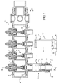
- a portion of a manifold for the circulation of a liquid, such as water for heating or cooling an environment is generically indicated as 1.
- the manifold 1 is formed by a series of annular elements 2, having axially: at one part an annular notch 3 having a tapered section, and on the other an annular edge 4, having a tapered section complementary to the notch 3.
- Each annular element 2 bears a radial element, consisting of a mouth 6 for attachment of a corresponding water circulation pipe end 7.
- Each element 2 is also equipped with a control valve 8, known in itself, adapted to open the mouth 6 in case of emergency.
- Each annular element 2 of the manifold 1 is connected to the adjacent elements 2, inserting the relative annular edge 4 in the annular notch 3 of the preceding element 2 above (on the left in Figure 1 ).
- Each edge 4 can be attached in the relative notch 3 by known means, like a screw or bolt or by welding, not shown in Figure 1 .
- the edge 4 of the first annular element 2 (on the left in Figure 1 ) is connected to a plug 9 having its own annular notch 3 equal to that of elements 2, while the annular notch 3 of the last element 2 (on the right in figure 1 ) is connected to a connecting group 11 having its tapered edge 4 equal to that of elements 2.
- the group 11 is capable of being connected to the boiler, in a known manner.
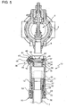
- each pipe 7 is attached to the mouth 6 of a corresponding annular element 2 of the manifold 1 by a joint generally indicated as 13.
- the joint 13 comprises a first tubular element 14 adapted to be attached to the mouth 6 of the annular element 2, and a second tubular element 16 connectable to the end portion 12 of the pipe 7 and adapted to be sealingly engaged on the tubular element 14 in an axially mobile position within a predetermined spatial region.
- a sectioned joint 13 is shown, already connected to the respective mouth 6, and centrally, a joint 13 in an external view unconnected to the respective mouth 6.
- tubular element 16 is designed as a male element of the joint 13, and is adapted to be engaged onto the tubular element 14, which is designed as a female element of the joint 13.
- the tubular element 16 comprises a sleeve 17 ( Figure 4 ) adapted to receive an end portion 12 of pipe 7, between an inner cylindrical wall 18 and an outer cylindrical wall 19.
- the two cylindrical walls 18 and 19 are coaxial and are connected together by an annular rib 21 defining the axial position of the end portion 12, with respect to the two cylindrical walls 18 and 19.
- a locking bushing 22, separated from the sleeve 17, is attachable in a predetermined axial position onto the tubular element 14 in such a way as to allow the axial sliding of the sleeve 17 with respect to said tubular element 14 towards the portion thereof connected to the mouth 6 and in such a way as to prevent the detachment of said sleeve 17 from the tubular element 14.
- the inner wall 18 of sleeve 17 has an outer surface having a tapered portion 23 corresponding to an edge 24 of the outer wall 19. Axially, between the edge 24 of outer wall 19 and an edge 26 of the bushing 22 a metallic annular locking element 27 having an internal area in the form of flexible fins, which engage the portion 12 of the pipe 7 is disposed.
- the locking element 27 has a slightly frustoconical shape with the smaller section facing the annular rib 21 of the sleeve 17, so as to allow the axial sliding of the portion 12 of the pipe 7 towards the said rib 21 and prevent the extraction of the pipe 7 in the opposite direction.
- a shaped metal ring 25 and a sealing annular gasket 28 of elastically deformable material are disposed between the locking element 27 and the edge 26 of the bushing 22 and disposed a shaped metal ring 25 and a sealing annular gasket 28 of elastically deformable material.
- the tubular element 14 of joint 13 is formed by a sleeve 29 having an inner cylindrical surface 31 and a outer surface 32 which at one of its extremities forms a reinforced edge 33.
- the sleeve 29 presents, opposite the edge 33, a portion 34 internally shaped, which is modeled for fitting the mouth 6, with the interposition of a gasket, indicated as a whole with 36.
- the said spatial region of movement of the tubular element 16 with respect to the tubular element 14 is axially delimited by opposite parts of the locking bushing 22 and by the shaped end portion 34 of the tubular element 14.
- the shaped portion 34 has a radial seat 37 (see also Figure 3 ), in which a snap fit mechanism 38 for the connection to the mouth 6 is disposed.
- the radial seat 37 comprises two parallel grooves 39 inside the sleeve 29, which end with two openings 40 and 41 of the sleeve 29 in the form of two circumferential slots, diametrally opposed to each other.
- the sleeve 29 has a rectangular shaped window 42 projecting outward.
- the snap fit mechanism 38 comprises a frame 43 formed by two parallel sides 44 sliding in the guides 39 and an arc of a circle-shaped crossed member 45, which, in use, is adapted to engage an annular groove 46 of mouth 6.
- the frame 43 has a curved plate 47 coaxial with the sleeve 29, which is integral with the sides 44 and opposed to the cross member 45. The plate 47 is adapted to slide into the window 42, so that the frame 43 functions like a drawer, closing the window 42.
- the plate 47 is provided with an external protrusion in the form of an button 48 capable of being pushed by a technician's finger.
- the plate 47 is internally provided with a pin 49, adapted to keep in place a flexible element formed by a helical frustoconical compression spring 51.
- the spring 51 is housed in a recess 52 of the sleeve 29, and is arranged with the smaller diameter end abutting against the plate 47 and the larger diameter end abutting against the recess 52, therefore, normally holding the cross member 45 in engagement with the groove 46, locking the sleeve 29 on the respective mouth 6, in the position of Figure 2 .
- the edge 33 of sleeve 29 has two substantially circumferential slit 53, each correspondingly disposed with an axial groove 54 in the inner surface 31, so as to form, with the slit 53, a reversed L shape.
- the bushing 22 has two radial appendixes 55 projecting radially from the bushing 22 and adapted to engage in a bayonet fashion the slit 53 through the grooves 54.
- the slits 53 have a slightly curved shape (see also Figure 1 ), in order to allow, with the rotation of the bushing 22, a tightening of the bayonet connection.
- the bushing 22 also presents a prismatic sectioned end portion 56 (see also Figure 6 ), for example hexagonal, allowing the connection and disconnection of the bushing 22 with the sleeve 29, through the use of a special wrench.
- connection of the pipe 7 to the respective mouth 6 of the manifold 1 is made as follows.
- the tubular elements 14 and 16 are supplied to the technician in a pre-assembly kit, in which the sleeve 17, the locking element 27, the shaped ring 25 the annular gasket 28 are inserted into the sleeve 29 of the tubular element 14 and are locked therein through engagement between the bushing 22 and the sleeve 29 itself.
- the bushing 22 is inserted into the sleeve 29, in such a way that the two radial appendages 55 engage the corresponding grooves 54, until reaching the corresponding slits 53; the simple rotation of the bushing 22, possibly by means of a wrench, therefore determines the bond between the tubular element 16 and the tubular element 14.
- the portion 12 of the pipe 7 is inserted within the tubular elements 16 and 14 provided in the pre-assembly kit (see Figure 4 ).
- the portion 12 of pipe 7 slides within the annular gasket 28, the shaped ring 25 and the locking element 27 to then be inserted between the two walls 18 and 19 of sleeve 17 until its end rests against the annular rib 21.
- the annular gasket 28 is thus compressed between the outer surface of portion 12 of the pipe 7 and the inner surface 31 of sleeve 29, ensuring the sealing of the joint 13.
- the portion 12 of the pipe 7 may possibly continue to slide along with the sleeve 17 inside the sleeve 29 until settling automatically in the position corresponding to its actual length. In this way, the pipe 7 can be cut to a variable length within a range depending on the axial distance between the locking bushing 22 and end portion 34 of the tubular element 14.
- the assembly formed by the tubular element 14, the tubular element 16, the locking bushing 22 and the pipe 7 is snap fitted to the mouth 6.
- the frame 43 is moved against the action of the spring 51, so as to allow full insertion of the mouth 6 in the end portion 34 of the tubular element 14.
- the cross member 45 of the frame 43 is then brought in correspondence with the groove 46 of the mouth 6, so that when releasing the button 48 the spring 51 triggers the frame 43 towards the window 42, engaging the cross member 45 within the groove 46 of the mouth 6.
- the sleeve 29 may be inserted and locked onto the mouth 6 at any angular position, therefore, the operation is very simple, especially since it requires no rotation of any component.
- the tubular element 14 of joint 13 is formed by a sleeve 29', which is equipped with a connecting portion 58 having a cylindrical area 59 of a reduced diameter, and a contoured area 61, upon which are provided two annular seats 62a, 62b adapted to receive respectively a gasket 63a, for example of the o-ring type, and a retaining ring 63b.
- the connecting portion 58 is also provided with a ring 64 having an inverted L-shaped section, with an axial wing 66 and a radial wing 67.
- the axial wing 66 is attached to the inner surface of the area 61, while the radial wing 67 locks the gasket 63b in its seat 62a.
- a threaded ring 68 Upon the cylindrical zone 59 of the connecting portion 58 is mounted a threaded ring 68, held in position between the retaining ring 63b and an annular shoulder settled between the connecting portion 58 and the remaining part of the tubular element 14; the threaded ring 68 presents an internally threaded portion 69, which is adapted to engage with the threaded portion 57 of the mouth 6'.
- connection of the pipe 7 with the tubular elements 14 and 16, already pre-assembled takes place in a completely identical way to that described above relative to the embodiment of Figures 1-6 ; whereas, regarding the final connection assembly thus formed on the mouth 6', one needs to simply screw the threaded ring 68 to the threaded portion 57, in such a way that the gasket 63a is compressed against the actual inner surface of the portion 57, as shown in Figure 7 .
- the snap fit mechanism 38 may be a contact clip instead of a frame.
Claims (9)
- Joint (13) pour le raccordement d'un tuyau (7) d'un système de chauffage et/ou de conditionnement d'air à une bouche (6, 6') d'un collecteur (1) du système lui-même, le joint (13) comprenant :un premier élément tubulaire (14) ayant une partie d'extrémité (34, 58) qui peut être fixée à ladite bouche (6, 6') ; etun second élément tubulaire (16) adapté pour être raccordé à une partie d'extrémité (12) dudit tuyau (7) et pour être mis en prise de manière étanche sur ledit premier élément tubulaire (14) dans une position qui peut être déplacée axialement à l'intérieur d'une région spatiale prédéterminée ;dans lequel lesdits premier et second éléments tubulaires (14, 16) sont un élément femelle et un élément mâle respectivement ;dans lequel ledit second élément tubulaire (16) comprend un manchon (17) adapté pour recevoir ladite partie d'extrémité (12) dudit tuyau (7) et couplé de manière à pouvoir être déplacé axialement par rapport audit premier élément tubulaire (14) ;dans lequel on prévoit une douille de verrouillage (22), séparée dudit manchon (17), qui peut être fixée dans une position axiale prédéterminée sur ledit premier élément tubulaire (14) et qui est adaptée pour permettre le coulissement axial dudit manchon (17) par rapport audit premier élément tubulaire (14) vers ladite partie d'extrémité (34, 58) du premier élément tubulaire (14) et pour empêcher le détachement dudit manchon (17) par rapport audit premier élément tubulaire (14) ;dans lequel ladite région spatiale est délimitée axialement sur des parties opposées par ladite douille de verrouillage (22) et par ladite partie d'extrémité (34, 58) dudit premier élément tubulaire (14),caractérisé en ce que ledit manchon (17) a une paroi interne cylindrique (18) et une paroi externe cylindrique (19) entre lesquelles ladite partie d'extrémité (12) dudit tuyau (7) est adaptée pour être insérée, et en ce que lesdites parois cylindriques (18, 19) sont raccordées l'une à l'autre au moyen d'un élément annulaire (21) adapté pour délimiter la position axiale de ladite partie d'extrémité (12) dudit tuyau (7) par rapport auxdites parois cylindriques (18, 19).
- Joint selon la revendication 1, dans lequel ladite douille (22) est adaptée pour être raccordée audit premier élément tubulaire (14) au moyen de moyens de mise en prise amovible (53-55).
- Joint selon la revendication 2, dans lequel lesdits moyens de mise en prise comprennent un joint à baïonnette (53-55).
- Joint selon l'une quelconque des revendications précédentes, dans lequel une garniture annulaire (28) est insérée entre ledit manchon (17) et ledit premier élément tubulaire (14).
- Joint selon l'une quelconque des revendications précédentes, dans lequel ledit second élément tubulaire (16) comprend un élément de verrouillage annulaire élastique (27) pour empêcher que ladite partie d'extrémité (12) dudit tuyau (7) ne soit retirée dudit manchon (17).
- Joint selon l'une quelconque des revendications précédentes, dans lequel il comprend un mécanisme d'ajustement par pression (38) pour le raccordement de ladite partie d'extrémité (34) dudit premier élément tubulaire sur ladite bouche (6).
- Joint selon la revendication 6, dans lequel ledit mécanisme d'ajustement par pression (38) comprend un châssis (43) ayant deux côtés parallèles (44) qui peuvent coulisser sur un siège radial (37) de ladite partie d'extrémité (34) dudit premier élément tubulaire (14), une traverse (45) pour le raccordement desdits côtés (44) étant normalement mise en prise avec une rainure annulaire (46) de ladite bouche (6) par un ressort (51).
- Joint selon la revendication 7, dans lequel ledit châssis (43) comprend, du côté diamétralement opposé à ladite traverse (45), un bouton de libération (48) qui est chargé élastiquement par ledit ressort (51).
- Joint selon l'une quelconque des revendications 1 à 5, dans lequel ladite partie d'extrémité (58) dudit premier élément tubulaire (14) porte une bague filetée (68) adaptée pour être vissée sur une partie filetée (57) de ladite bouche (6').
Applications Claiming Priority (1)
| Application Number | Priority Date | Filing Date | Title |
|---|---|---|---|
| IT000984A ITTO20080984A1 (it) | 2008-12-23 | 2008-12-23 | Raccordo per il collegamento di tubature di impianti di riscaldamento e/o climatizzazione |
Publications (2)
| Publication Number | Publication Date |
|---|---|
| EP2202441A1 EP2202441A1 (fr) | 2010-06-30 |
| EP2202441B1 true EP2202441B1 (fr) | 2014-03-19 |
Family
ID=41510708
Family Applications (1)
| Application Number | Title | Priority Date | Filing Date |
|---|---|---|---|
| EP09180483.1A Not-in-force EP2202441B1 (fr) | 2008-12-23 | 2009-12-22 | Raccord pour la connexion des tuyaux |
Country Status (2)
| Country | Link |
|---|---|
| EP (1) | EP2202441B1 (fr) |
| IT (1) | ITTO20080984A1 (fr) |
Cited By (1)
| Publication number | Priority date | Publication date | Assignee | Title |
|---|---|---|---|---|
| EP3388727A1 (fr) | 2017-04-13 | 2018-10-17 | Pres-Block S.P.A. | Ensemble de connexion destiné à un système de chauffage et/ou de climatisation |
Families Citing this family (2)
| Publication number | Priority date | Publication date | Assignee | Title |
|---|---|---|---|---|
| NL1037883C2 (en) * | 2010-04-13 | 2011-10-17 | Jvb Beheer B V | Pump module for use in a manifold for a floor heating system. |
| ITUB20154027A1 (it) | 2015-09-30 | 2017-03-30 | Roberto Messana | Giunto a innesto rapido scorrevole. |
Family Cites Families (8)
| Publication number | Priority date | Publication date | Assignee | Title |
|---|---|---|---|---|
| GB824986A (en) * | 1957-03-18 | 1959-12-09 | Rolls Royce | Improvements in or relating to pipe end fittings |
| US3669472A (en) * | 1971-02-03 | 1972-06-13 | Wiggins Inc E B | Coupling device with spring locking detent means |
| GB1438743A (en) * | 1974-10-04 | 1976-06-09 | Hepworth Plastics Ltd | Pipe couplings |
| US5511830A (en) * | 1994-09-20 | 1996-04-30 | Dana Corporation | Quick connect tube couplings |
| JP2000320759A (ja) * | 1999-05-14 | 2000-11-24 | Kubota Corp | 伸縮離脱防止継手 |
| DE102004012817A1 (de) * | 2004-03-16 | 2005-10-06 | Wolf Gmbh | Rohrverbindungselement |
| US7828336B2 (en) * | 2004-12-09 | 2010-11-09 | Adroit Development, Inc. | Quick disconnect safety connector |
| CA2626239C (fr) * | 2005-10-19 | 2014-09-09 | Jtl Australia Pty Ltd | Raccord de canalisation de type coulissant |
-
2008
- 2008-12-23 IT IT000984A patent/ITTO20080984A1/it unknown
-
2009
- 2009-12-22 EP EP09180483.1A patent/EP2202441B1/fr not_active Not-in-force
Cited By (1)
| Publication number | Priority date | Publication date | Assignee | Title |
|---|---|---|---|---|
| EP3388727A1 (fr) | 2017-04-13 | 2018-10-17 | Pres-Block S.P.A. | Ensemble de connexion destiné à un système de chauffage et/ou de climatisation |
Also Published As
| Publication number | Publication date |
|---|---|
| EP2202441A1 (fr) | 2010-06-30 |
| ITTO20080984A1 (it) | 2010-06-24 |
Similar Documents
| Publication | Publication Date | Title |
|---|---|---|
| US6612622B2 (en) | Rotatable quick connector | |
| US5425558A (en) | Quick-connect coupling | |
| US9175794B2 (en) | Device for connecting male and female piping | |
| CA2575483C (fr) | Raccord rapide pour fluide sur tubulure de raccordement avec interface de vanne d'arret | |
| EP3259509B1 (fr) | Système comprenant un conduit de fluide tubulaire et un accouplement hydraulique à raccord rapide avec un clapet anti-retour intégré | |
| CA2572953C (fr) | Robinet d'arret d'une alimentation d'eau comprenant un raccord rapide possedant une regulation d'ecoulement | |
| WO2000003886A2 (fr) | Raccord rapide a caracteristique de confirmation de verrouillage secondaire | |
| EP2202441B1 (fr) | Raccord pour la connexion des tuyaux | |
| JPH09505133A (ja) | 調整可能な圧力解放バルブを備えた流体カップリング | |
| US20080174108A1 (en) | Snap-in-place valved coupler | |
| JP5150190B2 (ja) | 管継手 | |
| EP1741967B1 (fr) | Dispositif de raccordement rapide pour conduits d'automobiles | |
| US6802491B1 (en) | Fluid shut off valve cartridge with quick connection | |
| WO2020205820A1 (fr) | Mécanisme de montage pour dispositifs thermostatiques | |
| GB2264340A (en) | A plug-in coupling for joining fluid conduits | |
| US7108296B2 (en) | Fluid quick connector for threaded fluid components | |
| US20050200126A1 (en) | Connecting device for fluid conduits | |
| EP1388715B1 (fr) | Dispositif pour connecter une tête de commande à une vanne thermostatique, notamment pour un radiateur ou pour d'autres appareils de conditionnement d'air ou d'appareils de chauffage | |
| US20210131578A1 (en) | Modular Valve System | |
| WO2007109729A2 (fr) | Raccord de fluide à raccordement rapide | |
| CN212080237U (zh) | 水龙头内本体快速安装构造 | |
| EP1724511B1 (fr) | Raccord rapide avec pièce de maintien | |
| RU2443933C1 (ru) | Устройство для соединения двух жестких объектов | |
| JP2005048398A (ja) | 配管接続構造 | |
| WO2021113942A1 (fr) | Agencement d'accouplement à mise en prise rapide pour systèmes pneumatiques |
Legal Events
| Date | Code | Title | Description |
|---|---|---|---|
| PUAI | Public reference made under article 153(3) epc to a published international application that has entered the european phase |
Free format text: ORIGINAL CODE: 0009012 |
|
| AK | Designated contracting states |
Kind code of ref document: A1 Designated state(s): AT BE BG CH CY CZ DE DK EE ES FI FR GB GR HR HU IE IS IT LI LT LU LV MC MK MT NL NO PL PT RO SE SI SK SM TR |
|
| AX | Request for extension of the european patent |
Extension state: AL BA RS |
|
| 17P | Request for examination filed |
Effective date: 20101230 |
|
| 17Q | First examination report despatched |
Effective date: 20110621 |
|
| RIC1 | Information provided on ipc code assigned before grant |
Ipc: F24D 3/10 20060101ALI20130627BHEP Ipc: F16L 37/084 20060101ALI20130627BHEP Ipc: F16L 27/12 20060101AFI20130627BHEP |
|
| GRAP | Despatch of communication of intention to grant a patent |
Free format text: ORIGINAL CODE: EPIDOSNIGR1 |
|
| INTG | Intention to grant announced |
Effective date: 20131003 |
|
| GRAS | Grant fee paid |
Free format text: ORIGINAL CODE: EPIDOSNIGR3 |
|
| GRAA | (expected) grant |
Free format text: ORIGINAL CODE: 0009210 |
|
| AK | Designated contracting states |
Kind code of ref document: B1 Designated state(s): AT BE BG CH CY CZ DE DK EE ES FI FR GB GR HR HU IE IS IT LI LT LU LV MC MK MT NL NO PL PT RO SE SI SK SM TR |
|
| REG | Reference to a national code |
Ref country code: GB Ref legal event code: FG4D |
|
| REG | Reference to a national code |
Ref country code: CH Ref legal event code: EP |
|
| REG | Reference to a national code |
Ref country code: IE Ref legal event code: FG4D |
|
| REG | Reference to a national code |
Ref country code: AT Ref legal event code: REF Ref document number: 657903 Country of ref document: AT Kind code of ref document: T Effective date: 20140415 |
|
| REG | Reference to a national code |
Ref country code: DE Ref legal event code: R096 Ref document number: 602009022578 Country of ref document: DE Effective date: 20140430 |
|
| PG25 | Lapsed in a contracting state [announced via postgrant information from national office to epo] |
Ref country code: NO Free format text: LAPSE BECAUSE OF FAILURE TO SUBMIT A TRANSLATION OF THE DESCRIPTION OR TO PAY THE FEE WITHIN THE PRESCRIBED TIME-LIMIT Effective date: 20140619 Ref country code: LT Free format text: LAPSE BECAUSE OF FAILURE TO SUBMIT A TRANSLATION OF THE DESCRIPTION OR TO PAY THE FEE WITHIN THE PRESCRIBED TIME-LIMIT Effective date: 20140319 |
|
| REG | Reference to a national code |
Ref country code: NL Ref legal event code: VDEP Effective date: 20140319 |
|
| REG | Reference to a national code |
Ref country code: AT Ref legal event code: MK05 Ref document number: 657903 Country of ref document: AT Kind code of ref document: T Effective date: 20140319 |
|
| REG | Reference to a national code |
Ref country code: LT Ref legal event code: MG4D |
|
| PG25 | Lapsed in a contracting state [announced via postgrant information from national office to epo] |
Ref country code: CY Free format text: LAPSE BECAUSE OF FAILURE TO SUBMIT A TRANSLATION OF THE DESCRIPTION OR TO PAY THE FEE WITHIN THE PRESCRIBED TIME-LIMIT Effective date: 20140319 Ref country code: FI Free format text: LAPSE BECAUSE OF FAILURE TO SUBMIT A TRANSLATION OF THE DESCRIPTION OR TO PAY THE FEE WITHIN THE PRESCRIBED TIME-LIMIT Effective date: 20140319 Ref country code: SE Free format text: LAPSE BECAUSE OF FAILURE TO SUBMIT A TRANSLATION OF THE DESCRIPTION OR TO PAY THE FEE WITHIN THE PRESCRIBED TIME-LIMIT Effective date: 20140319 |
|
| PG25 | Lapsed in a contracting state [announced via postgrant information from national office to epo] |
Ref country code: LV Free format text: LAPSE BECAUSE OF FAILURE TO SUBMIT A TRANSLATION OF THE DESCRIPTION OR TO PAY THE FEE WITHIN THE PRESCRIBED TIME-LIMIT Effective date: 20140319 Ref country code: HR Free format text: LAPSE BECAUSE OF FAILURE TO SUBMIT A TRANSLATION OF THE DESCRIPTION OR TO PAY THE FEE WITHIN THE PRESCRIBED TIME-LIMIT Effective date: 20140319 |
|
| PG25 | Lapsed in a contracting state [announced via postgrant information from national office to epo] |
Ref country code: BG Free format text: LAPSE BECAUSE OF FAILURE TO SUBMIT A TRANSLATION OF THE DESCRIPTION OR TO PAY THE FEE WITHIN THE PRESCRIBED TIME-LIMIT Effective date: 20140619 Ref country code: IS Free format text: LAPSE BECAUSE OF FAILURE TO SUBMIT A TRANSLATION OF THE DESCRIPTION OR TO PAY THE FEE WITHIN THE PRESCRIBED TIME-LIMIT Effective date: 20140719 Ref country code: RO Free format text: LAPSE BECAUSE OF FAILURE TO SUBMIT A TRANSLATION OF THE DESCRIPTION OR TO PAY THE FEE WITHIN THE PRESCRIBED TIME-LIMIT Effective date: 20140319 Ref country code: CZ Free format text: LAPSE BECAUSE OF FAILURE TO SUBMIT A TRANSLATION OF THE DESCRIPTION OR TO PAY THE FEE WITHIN THE PRESCRIBED TIME-LIMIT Effective date: 20140319 Ref country code: BE Free format text: LAPSE BECAUSE OF FAILURE TO SUBMIT A TRANSLATION OF THE DESCRIPTION OR TO PAY THE FEE WITHIN THE PRESCRIBED TIME-LIMIT Effective date: 20140319 Ref country code: NL Free format text: LAPSE BECAUSE OF FAILURE TO SUBMIT A TRANSLATION OF THE DESCRIPTION OR TO PAY THE FEE WITHIN THE PRESCRIBED TIME-LIMIT Effective date: 20140319 Ref country code: EE Free format text: LAPSE BECAUSE OF FAILURE TO SUBMIT A TRANSLATION OF THE DESCRIPTION OR TO PAY THE FEE WITHIN THE PRESCRIBED TIME-LIMIT Effective date: 20140319 |
|
| PG25 | Lapsed in a contracting state [announced via postgrant information from national office to epo] |
Ref country code: AT Free format text: LAPSE BECAUSE OF FAILURE TO SUBMIT A TRANSLATION OF THE DESCRIPTION OR TO PAY THE FEE WITHIN THE PRESCRIBED TIME-LIMIT Effective date: 20140319 Ref country code: PL Free format text: LAPSE BECAUSE OF FAILURE TO SUBMIT A TRANSLATION OF THE DESCRIPTION OR TO PAY THE FEE WITHIN THE PRESCRIBED TIME-LIMIT Effective date: 20140319 Ref country code: SK Free format text: LAPSE BECAUSE OF FAILURE TO SUBMIT A TRANSLATION OF THE DESCRIPTION OR TO PAY THE FEE WITHIN THE PRESCRIBED TIME-LIMIT Effective date: 20140319 Ref country code: ES Free format text: LAPSE BECAUSE OF FAILURE TO SUBMIT A TRANSLATION OF THE DESCRIPTION OR TO PAY THE FEE WITHIN THE PRESCRIBED TIME-LIMIT Effective date: 20140319 |
|
| REG | Reference to a national code |
Ref country code: DE Ref legal event code: R097 Ref document number: 602009022578 Country of ref document: DE |
|
| PG25 | Lapsed in a contracting state [announced via postgrant information from national office to epo] |
Ref country code: PT Free format text: LAPSE BECAUSE OF FAILURE TO SUBMIT A TRANSLATION OF THE DESCRIPTION OR TO PAY THE FEE WITHIN THE PRESCRIBED TIME-LIMIT Effective date: 20140721 |
|
| PLBE | No opposition filed within time limit |
Free format text: ORIGINAL CODE: 0009261 |
|
| STAA | Information on the status of an ep patent application or granted ep patent |
Free format text: STATUS: NO OPPOSITION FILED WITHIN TIME LIMIT |
|
| PG25 | Lapsed in a contracting state [announced via postgrant information from national office to epo] |
Ref country code: DK Free format text: LAPSE BECAUSE OF FAILURE TO SUBMIT A TRANSLATION OF THE DESCRIPTION OR TO PAY THE FEE WITHIN THE PRESCRIBED TIME-LIMIT Effective date: 20140319 |
|
| 26N | No opposition filed |
Effective date: 20141222 |
|
| REG | Reference to a national code |
Ref country code: DE Ref legal event code: R097 Ref document number: 602009022578 Country of ref document: DE Effective date: 20141222 |
|
| PG25 | Lapsed in a contracting state [announced via postgrant information from national office to epo] |
Ref country code: SI Free format text: LAPSE BECAUSE OF FAILURE TO SUBMIT A TRANSLATION OF THE DESCRIPTION OR TO PAY THE FEE WITHIN THE PRESCRIBED TIME-LIMIT Effective date: 20140319 Ref country code: LU Free format text: LAPSE BECAUSE OF FAILURE TO SUBMIT A TRANSLATION OF THE DESCRIPTION OR TO PAY THE FEE WITHIN THE PRESCRIBED TIME-LIMIT Effective date: 20141222 |
|
| REG | Reference to a national code |
Ref country code: CH Ref legal event code: PL |
|
| REG | Reference to a national code |
Ref country code: IE Ref legal event code: MM4A |
|
| PG25 | Lapsed in a contracting state [announced via postgrant information from national office to epo] |
Ref country code: IE Free format text: LAPSE BECAUSE OF NON-PAYMENT OF DUE FEES Effective date: 20141222 Ref country code: LI Free format text: LAPSE BECAUSE OF NON-PAYMENT OF DUE FEES Effective date: 20141231 Ref country code: CH Free format text: LAPSE BECAUSE OF NON-PAYMENT OF DUE FEES Effective date: 20141231 |
|
| REG | Reference to a national code |
Ref country code: FR Ref legal event code: PLFP Year of fee payment: 7 |
|
| PGFP | Annual fee paid to national office [announced via postgrant information from national office to epo] |
Ref country code: DE Payment date: 20151215 Year of fee payment: 7 Ref country code: GB Payment date: 20151216 Year of fee payment: 7 |
|
| PGFP | Annual fee paid to national office [announced via postgrant information from national office to epo] |
Ref country code: FR Payment date: 20151110 Year of fee payment: 7 |
|
| PG25 | Lapsed in a contracting state [announced via postgrant information from national office to epo] |
Ref country code: SM Free format text: LAPSE BECAUSE OF FAILURE TO SUBMIT A TRANSLATION OF THE DESCRIPTION OR TO PAY THE FEE WITHIN THE PRESCRIBED TIME-LIMIT Effective date: 20140319 |
|
| PGFP | Annual fee paid to national office [announced via postgrant information from national office to epo] |
Ref country code: IT Payment date: 20151203 Year of fee payment: 7 |
|
| PG25 | Lapsed in a contracting state [announced via postgrant information from national office to epo] |
Ref country code: MC Free format text: LAPSE BECAUSE OF FAILURE TO SUBMIT A TRANSLATION OF THE DESCRIPTION OR TO PAY THE FEE WITHIN THE PRESCRIBED TIME-LIMIT Effective date: 20140319 |
|
| PG25 | Lapsed in a contracting state [announced via postgrant information from national office to epo] |
Ref country code: GR Free format text: LAPSE BECAUSE OF FAILURE TO SUBMIT A TRANSLATION OF THE DESCRIPTION OR TO PAY THE FEE WITHIN THE PRESCRIBED TIME-LIMIT Effective date: 20140620 |
|
| PG25 | Lapsed in a contracting state [announced via postgrant information from national office to epo] |
Ref country code: HU Free format text: LAPSE BECAUSE OF FAILURE TO SUBMIT A TRANSLATION OF THE DESCRIPTION OR TO PAY THE FEE WITHIN THE PRESCRIBED TIME-LIMIT; INVALID AB INITIO Effective date: 20091222 Ref country code: TR Free format text: LAPSE BECAUSE OF FAILURE TO SUBMIT A TRANSLATION OF THE DESCRIPTION OR TO PAY THE FEE WITHIN THE PRESCRIBED TIME-LIMIT Effective date: 20140319 Ref country code: MT Free format text: LAPSE BECAUSE OF FAILURE TO SUBMIT A TRANSLATION OF THE DESCRIPTION OR TO PAY THE FEE WITHIN THE PRESCRIBED TIME-LIMIT Effective date: 20140319 |
|
| REG | Reference to a national code |
Ref country code: DE Ref legal event code: R119 Ref document number: 602009022578 Country of ref document: DE |
|
| GBPC | Gb: european patent ceased through non-payment of renewal fee |
Effective date: 20161222 |
|
| REG | Reference to a national code |
Ref country code: FR Ref legal event code: ST Effective date: 20170831 |
|
| PG25 | Lapsed in a contracting state [announced via postgrant information from national office to epo] |
Ref country code: FR Free format text: LAPSE BECAUSE OF NON-PAYMENT OF DUE FEES Effective date: 20170102 Ref country code: IT Free format text: LAPSE BECAUSE OF NON-PAYMENT OF DUE FEES Effective date: 20161222 |
|
| PG25 | Lapsed in a contracting state [announced via postgrant information from national office to epo] |
Ref country code: DE Free format text: LAPSE BECAUSE OF NON-PAYMENT OF DUE FEES Effective date: 20170701 Ref country code: GB Free format text: LAPSE BECAUSE OF NON-PAYMENT OF DUE FEES Effective date: 20161222 |
|
| PG25 | Lapsed in a contracting state [announced via postgrant information from national office to epo] |
Ref country code: MK Free format text: LAPSE BECAUSE OF FAILURE TO SUBMIT A TRANSLATION OF THE DESCRIPTION OR TO PAY THE FEE WITHIN THE PRESCRIBED TIME-LIMIT Effective date: 20140319 |