EP2201673B1 - Stromversorgungssystem mit zweifacher synchronisation - Google Patents
Stromversorgungssystem mit zweifacher synchronisation Download PDFInfo
- Publication number
- EP2201673B1 EP2201673B1 EP20070839713 EP07839713A EP2201673B1 EP 2201673 B1 EP2201673 B1 EP 2201673B1 EP 20070839713 EP20070839713 EP 20070839713 EP 07839713 A EP07839713 A EP 07839713A EP 2201673 B1 EP2201673 B1 EP 2201673B1
- Authority
- EP
- European Patent Office
- Prior art keywords
- power
- generator
- engine
- engines
- common bus
- Prior art date
- Legal status (The legal status is an assumption and is not a legal conclusion. Google has not performed a legal analysis and makes no representation as to the accuracy of the status listed.)
- Not-in-force
Links
Images
Classifications
-
- H—ELECTRICITY
- H02—GENERATION; CONVERSION OR DISTRIBUTION OF ELECTRIC POWER
- H02P—CONTROL OR REGULATION OF ELECTRIC MOTORS, ELECTRIC GENERATORS OR DYNAMO-ELECTRIC CONVERTERS; CONTROLLING TRANSFORMERS, REACTORS OR CHOKE COILS
- H02P9/00—Arrangements for controlling electric generators for the purpose of obtaining a desired output
- H02P9/04—Control effected upon non-electric prime mover and dependent upon electric output value of the generator
-
- B—PERFORMING OPERATIONS; TRANSPORTING
- B63—SHIPS OR OTHER WATERBORNE VESSELS; RELATED EQUIPMENT
- B63J—AUXILIARIES ON VESSELS
- B63J3/00—Driving of auxiliaries
- B63J3/02—Driving of auxiliaries from propulsion power plant
-
- H—ELECTRICITY
- H02—GENERATION; CONVERSION OR DISTRIBUTION OF ELECTRIC POWER
- H02J—ELECTRIC POWER NETWORKS; CIRCUIT ARRANGEMENTS OR SYSTEMS FOR SUPPLYING OR DISTRIBUTING ELECTRIC POWER; SYSTEMS FOR STORING ELECTRIC ENERGY
- H02J3/00—Circuit arrangements for AC mains or AC distribution networks
- H02J3/38—Arrangements for feeding a single network from two or more generators or sources in parallel; Arrangements for feeding already energised networks from additional generators or sources in parallel
- H02J3/40—Synchronisation of generators for connection to a network or to another generator
- H02J3/42—Synchronisation of generators for connection to a network or to another generator with automatic parallel connection when synchronisation is achieved
-
- H—ELECTRICITY
- H02—GENERATION; CONVERSION OR DISTRIBUTION OF ELECTRIC POWER
- H02P—CONTROL OR REGULATION OF ELECTRIC MOTORS, ELECTRIC GENERATORS OR DYNAMO-ELECTRIC CONVERTERS; CONTROLLING TRANSFORMERS, REACTORS OR CHOKE COILS
- H02P9/00—Arrangements for controlling electric generators for the purpose of obtaining a desired output
- H02P9/10—Control effected upon generator excitation circuit to reduce harmful effects of overloads or transients, e.g. sudden application of load, sudden removal of load, sudden change of load
-
- H—ELECTRICITY
- H02—GENERATION; CONVERSION OR DISTRIBUTION OF ELECTRIC POWER
- H02J—ELECTRIC POWER NETWORKS; CIRCUIT ARRANGEMENTS OR SYSTEMS FOR SUPPLYING OR DISTRIBUTING ELECTRIC POWER; SYSTEMS FOR STORING ELECTRIC ENERGY
- H02J2105/00—Networks for supplying or distributing electric power characterised by their spatial reach or by the load
- H02J2105/30—Networks for supplying or distributing electric power characterised by their spatial reach or by the load the load networks being external to vehicles, i.e. exchanging power with vehicles
- H02J2105/31—Networks for supplying or distributing electric power characterised by their spatial reach or by the load the load networks being external to vehicles, i.e. exchanging power with vehicles for ships or vessels
Definitions
- the present disclosure relates generally to a power system and, more particularly, to a power system having dual synchronization.
- vibrations from the various generator sets can travel through the mountings thereof and either dampen or amplify. Vibrations within the power plant or onboard the marine vessel can be excessive when the engines of the generator sets have odd numbers of cylinders. That is, an engine having an odd number of cylinders is mechanically unbalanced. For example, in a nine-cylinder engine, four pistons may be moving upward, while five pistons are moving downward. As a result of the unbalanced masses and their movements, there will be a greater resultant force in the downward direction of this example.
- this force could be significant enough to transmit vibrations into the engine mounts and surrounding supports with enough amplitude that structural damage could occur and/or that the vibrations become a nuisance for the engine owner/operator.
- This is also a problem when multiple engines located near each other are operated in sync with each other (i.e., when eight pistons are moving upward and ten are moving downward, as would be the case with two closely operating nine-cylinder engines).
- U.S. Patent No. 6,552,454 (the '454 patent) issued to Kern et al. on April 22, 2003.
- the '454 patent discloses a generator structure having first and second generator sets positioned within a common enclosure. Each generator set includes an engine and an alternator driven by the engine for generating electrical power. The first generator set produces electrical power of a first magnitude and frequency, and the second generator set produces electrical power of a second magnitude and frequency.
- the generator structure also includes a controller that monitors the magnitude and phase of the electrical power produced by the first and second generator sets, and adjusts the speed of the engines via an electronic governor such the power produced by the first and second generators is brought into alignment with each other, no phase difference between the associated sine waves exist, and so that the sine waves are at the same frequency.
- the system controller regulates the output voltages of the generator sets such that the output voltages are generally equal. Once the frequency and output voltages are synchronized, the system controller closes switches to connect the power from the first and second generator sets to a load.
- the generator structure of the '454 patent may allow phase, frequency, and voltage matching, it does little to account for vibrations caused by imbalanced engines. And, because the generator sets are close-coupled in a common enclosure, depending on when the engines are electrically synchronized, it may be possible for the two generators to be electrically synchronized when the two associated engines are in phase with each other. And, if the engines are in phase enough and imbalanced, the vibrations could be severe enough to damage the common enclosure.
- JP 06-245390 a power system including multiple generator sets is disclosed.
- Each generator set has a generator driven by an internal combustion engine.
- the rotor of each generator is linked to the crankshaft of its paired engine at a precise and known angle, and the link angle of each generator set is chosen to be different to optimize vibration cancelling.
- the known power system relies on the known link angle of each generator set, when synchronizing the electrical output of each generator, to also automatically provide mechanical synchronization that results in a minimum total vibration. As long as the phase and frequency of rotors of each generator are synchronized with each other, mechanical synchronization might be automatic and may produce the least vibration.
- the known power system implements stringent assembly processes to obtain a precise dual synchronization during a single attempt that results in the lowest overall vibration possible.
- the known power system might be problematic, if a generator rotor is bolted to an engine's crankshaft at whatever angle is available at the time.
- JP 03-134897 also includes multiple generator sets that each have a generator driven by an internal combustion engine.
- the crankshaft of each engine includes an optical marker that corresponds with a particular mechanical phase.
- a maximum vibration canceling might be achieved.
- the known power system describes electrically synchronizing the output of the two generators and then checking synchronization of the two markers. If the two markers are synchronized at the time of electrical synch, the breaker is closed. If not, electrical synch is restarted. There is no discussion as to what happens if the two synchs do not coincide.
- the power system of the present disclosure addresses one or more of the problems set forth above.
- the present disclosure is directed toward a power system.
- the power system comprises a first generator set having a first engine drivingly coupled to a first generator and a second generator set having a second engine drivingly coupled to a second generator.
- the power system also includes a common bus and a controller in communication with the first and second generator sets.
- the controller is configured to synchronize a power output from the second generator with a power output from the first generator (22), and direct power from the first generator to the common bus.
- the controller also is configured to direct power from the second generator to the common bus only when the first and second engines are substantially mechanically synchronized, i.e.
- the rotational angles of the first and second engines are within 170-190° out of phase with each other, and postpone power from the second generator being directed to the common bus until the first and second engines are substantially mechanically synchronized.
- the controller is configured to attempt mechanical synchronization a number of times, and direct power from the second generator to the common bus after power output synchronization regardless of mechanical synchronization when the number of attempts has been made.
- the present disclosure is directed toward a method of providing power.
- the method includes operating a first power source to produce electrical power, and directing power from the first power source to a common bus.
- the method further includes operating a second power source to produce electrical power, and synchronizing a power output from the second power source with a power output from the first power source.
- the method additionally includes directing power from the second power source to the common bus only when the first and second power sources are substantially mechanically synchronized, i.e. the rotational angles of the first and second engines are within 170-190° out of phase with each other.
- the method further includes postponing directing power from the second power source to the common bus until the first and second power sources are substantially mechanically synchronized.
- the method also includes attempting mechanical synchronization a number of times, and directing power from the second power source to the common bus after power output synchronization regardless of mechanical synchronization when the number of attempts has been made.
- the present disclosure is directed toward a power facility.
- the power facility comprises a common anchor platform and a power system of the type mentioned above.
- the first generator set is mounted to the common anchor platform and has a first mass-imbalanced engine drivingly coupled to a first generator.
- the second generator set is mounted to the common anchor platform in proximity to the first generator set and has a second mass-imbalanced engine drivingly coupled to a second generator.
- the common bus is configured to transmit electrical power from the first and second generator sets to a power load.
- controller is configured to postpone power from the second generator being directed to the common bus until the first and second mass-imbalanced engines are substantially mechanically synchronized and a vibrational input directed from the first generator set into the common anchor platform is at least partially dampened by a vibrational input from the second generator set.
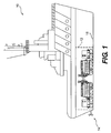
- Fig. 1 is a pictorial illustration of one exemplary disclosed power facility
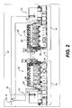
- Fig. 2 is a cutaway view of an exemplary disclosed power system that may be used with the power facility of Fig. 1 ;
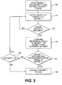
- Fig. 3 is a flow chart depicting an exemplary disclosed operation associated with the power system of Fig. 2 .
- Fig. 1 illustrates a power facility 10 having a power system 12 configured to supply electricity to a power load 14.
- power facility 10 may alternatively embody, for example, a stationary land-based power plant.
- Power facility 10 may include an anchor platform 16 such as a support frame connected to a hull of power facility 10, and to which power system 12 may be mounted. It is contemplated that power system 12 may be rigidly or flexibly mounted to anchor platform 16.
- power load 14 may include any device or devices that require uninterrupted electricity to perform one or more tasks, including, but not limited, electric lights and electric drive motors associated with the depicted marine vessel.
- power load 14 may require electric power in a particular form, such as three-phase alternating current.
- power system 12 may include at least two closely-located power sources 18 operable to generate electricity, and a power-transmission network such as a common bus 19 for transferring electricity from power sources 18 to power load 14 (referring to Fig. 1 ).
- each power source 18 may include an engine 20 drivingly coupled to a generator 22 to form a generator set.
- the generator sets may alternatively be located side-by-side or in a random arrangement within a common power room.
- Each engine 20 may be any type of heat engine operable to produce mechanical power by combusting fuel, including, but not limited to, a diesel engine, a heavy fuel engine, a gasoline engine, and a gaseous-fuel-powered engine.
- each engine 20 may be imbalanced. That is, each engine 20 may have an odd number of cylinders 24 resulting in a free mass or free mass moment.
- engine 20 may include nine cylinders 24. With respect to the nine-cylinder example, four pistons 26 may connected to a common crankshaft 28 and be moving upward, while five piston 26 also connected to crankshaft 28 are moving downward. As a result of the unbalanced masses and their movements, there will be a greater resultant force in the downward direction of this example.
- This greater force is known as a free mass. If unaccounted for, the free mass can induce significant vibrations into anchor platform 16. And, when multiple engines 20 are proximally located and operating in phase with each other (i.e., crankshafts 28 of each engine 20 are oriented at about the same angle and rotating at about the same speed), the magnitude of the amplified vibrations may be excessive.
- a sensor 30 may be associated with each engine 20 to detect an instantaneous position of each crankshaft 28.
- sensor 30 may embody, for example, an impulse transmitter configured to generate a pulse signal each time crankshaft 28 passes through a particular angle. For example, when crankshaft 28 of one engine 20 rotates the majority of pistons 26 to pass through a top dead center (TDC) position, the associated impulse transmitter may generate a first electronic pulse. Similarly, when crankshaft 28 of a second engine 20 rotates the majority of pistons 26 to pass through a bottom dead center (BDC) position, the associated impulse transmitter may generate a second electronic pulse.
- TDC top dead center
- BDC bottom dead center
- the engines when the first and second electronic pulses are generated at about the same time, the engines may be about 180° out of phase and the resulting vibrations may substantially dampen or even cancel each other completely.
- a greater time between the first and second pulses may correspond with engines 20 that are substantially in phase with each other and the resulting vibrations may be additive.
- sensor 30 may alternatively be associated with generators 22, for example with rotors that are directly driven by engine 20, and/or with windings of generators 22.
- Each generator 22 may be any type of power producing device mechanically coupled to receive power from engine 20 and convert at least a portion of that mechanical power into electricity.
- each generator 22 may embody an AC induction generator, a permanent-magnet generator, an AC synchronous generator, or a switched-reluctance generator.
- each generator 22 may include seven pairings of poles (not shown), each pairing having three phases arranged on a circumference of a stator (not shown) to produce an alternating current with a frequency of 60 Hz.
- Power system 12 may also include a synchronizing and load sharing controller 32 to regulate operation of power system 12.
- Controller 32 may include commonly known components that cooperate to synchronize the electrical output of multiple power sources 18 and combine the output into a common supply of power directed to load 14 (referring to Fig 1 ).
- controller 32 may include, among other things, one or more breakers (not shown) connected between each generator 22 and common bus 19 and/or between common bus 19 and power load 14 to selective connect the electrical output from one or both generators 22 to common bus 19 and/or to selectively connect common bus 19 to power load 14.
- controller 32 may be in communication with each engine 20, each generator 22, and sensors 30 to monitor and/or control one or more aspects of generator set operation.
- Controller 32 may further include one or more sensing devices (not shown) to receive input regarding characteristics of electricity generated by each power source 18 such as the current, frequency, phase, and/or voltage. Additionally, controller 32 may receive information relating to the amount of power required by power load 14. For example, controller 32 may receive information such as the voltage and/or current along one or more portions of common bus 19, and the voltage and/or current in one or more components of power load 14.
- Closing a first breaker associated with a first one of generators 22 may electrically connect the output of that generator 22 to common bus 19.
- Controller 32 may regulate operation of the additional power source 18 (i.e., engine 20 and/or generator 22) to vary the electrical output characteristics of the produced power and match the electrical output characteristics of the first generator 22.
- a breaker close command may be issued by controller 32 to the breaker associated with the second generator 22 and, after a brief actuation delay, the breaker may close.
- Controller 32 in addition to synchronizing the power outputs of multiple generators 22, may also control mechanical synchronization of the engines 20 driving those generators 22. Specifically, after electrical synchronization and before controller 32 issues the breaker close command in an attempt to bring additional generators 22 online, controller 32 may first check via sensors 30 to see if the associated first and additional engines 20 are operating in phase with each other (i.e., if the majority of pistons 26 from one engine 20 are moving to TDC at about the same time as the majority of pistons 26 from the second engine 20). If the associated engines 20 are operating sufficiently out of phase with each, controller 32 may go ahead and issue the breaker close command.
- controller 32 may postpone bringing the additional generators 22 online and abort the current synchronization attempt. Controller 32 may initiate another synchronization attempt and repeat the same synchronization cycle a number of times. In one embodiment, controller 32 may attempt dual synchronization (electrical and mechanical) up to ten times before initiating a backup strategy. During the backup strategy, controller 32 may issue the breaker close command regardless of mechanical synchronization. In this manner, load 14 may experience only a minor delay in power supply when mechanical synchronization is unsuccessful.
- Fig. 3 is a flow chart depicting an exemplary operation of power system 12. Fig. 3 will be discussed in the following section to further illustrate the disclosed system and its operation.
- the disclosed power system may have application wherever electrical and mechanical balancing is desired, for example, when multiple power sources having imbalanced moving masses are proximally located.
- electrical and mechanical synchronizing i.e., dual synchronizing
- each power source 18 may be started, and power from one source 18 may be directed to common bus 19 (Step 100).
- the associated engine 20 may be brought up to speed to drive the connected generators 22. In some situations, bringing engine 20 up to speed may include cranking to initiate combustion. In other situations, engine 20 may already be operating, but at only a standby level.
- controller 32 may issue a breaker close command to electrically connect the output of that generator 22 to common bus 19.
- additional generators 22 may also be producing power at the level demanded by load 14, they may remain isolated from common bus 19 until the power output from the additional generators 22 substantially match the power output of the first connected generator 22.
- Controller 32 may match the power output from additional generators 22 to that of the first connected generator 22 before additional connections to common bus 19 may be made (Step 110). Controller 32 may regulate operational characteristics of the additional engines 20 and/or generators 22 to vary and substantially match frequencies, phase angles, and voltages. Once controller 32 determines that the power output of any additional generators 22 substantially match the power output of the first connected generator 22 (Step 120), controller 32 may check the mechanical synchronization between engines 20. That is, controller 32 may compare the mechanical phase angle of the engine 20 associated with the first connected generator 22 with the mechanical phase angle of the remaining engines 20 via sensors 30 (Step 130).
- controller 32 may issue additional breaker close commands to connect the remaining generators 22 to common bus 19 (Step 150).
- the acceptable range is 170-190°.
- controller 32 may abort the current synchronizing attempt and determine the number of attempts made thus far in the process (Step 160). If the number of attempts is less than an acceptable number, for example ten attempts, the process may be restarted by returning control to step 110. However, if the acceptable number of attempts has been made, controller 32 may, instead, connect the electrical output from the additional generators 22 to common bus 19 regardless of mechanical synchronization (Step 150). In this manner, when mechanical synchronization is not possible or has been unsuccessful, power supply delays associated with an excessive number of attempts may be minimized.
- controller 32 may also control both electrical and mechanical synchronization of more than two generator sets. It should be noted, however, that if more that two generator sets are to mechanically synchronized, the out-of-phase angle would be different than disclosed above (i.e., different than 180°) and a function of the number of engines requiring mechanical synchronization.
- engine 20 may include nine cylinders 24It is intended that the specification and examples be considered as exemplary only, with a true scope of the disclosure being indicated by the following claims and their equivalents.
Landscapes
- Engineering & Computer Science (AREA)
- Power Engineering (AREA)
- Chemical & Material Sciences (AREA)
- Combustion & Propulsion (AREA)
- Mechanical Engineering (AREA)
- Ocean & Marine Engineering (AREA)
- Supply And Distribution Of Alternating Current (AREA)
- Control Of Eletrric Generators (AREA)
Claims (14)
- Leistungssystem (12) mit:- einem ersten Generatorsatz mit einem ersten Verbrennungsmotor (20), der antriebsmäßig mit einem ersten Generator (22) gekoppelt ist,- einem zweiten Generatorsatz mit einem zweiten Verbrennungsmotor (20), der antriebsmäßig mit einem zweiten Generator (22) gekoppelt ist,- einer Sammelschiene (19), und- einer mit dem ersten und dem zweiten Generatorsatz in Verbindung stehenden Steuerung (32), wobei die Steuerung dazu ausgebildet ist:eine Abgabeleistung des zweiten Generators (22) mit einer Abgabeleistung des ersten Generators (22) zu synchronisieren,Leistung von dem ersten Generator (22) zu der Sammelschiene (19) zu leiten,Leistung von dem zweiten Generator (22) nur dann zu der Sammelschiene (19) zu leiten, wenn der erste und der zweite Verbrennungsmotor (20, 20) im Wesentlichen mechanisch synchronisiert sind, d.h., die Drehwinkel des ersten und des zweiten Verbrennungsmotors (20, 20) zwischen 170-190° voneinander phasenversetzt sind,Leistung von dem zweiten Generator (22), die zu der Sammelschiene (19) geleitet werden soll, zurückzuhalten bis der erste und der zweite Verbrennungsmotor (20, 20) im Wesentlichen mechanisch synchronisiert sind,mehrere Male eine mechanische Synchronisation zu versuchen, undnach der Synchronisation der Abgabeleistungn, unabhängig von der mechanischen Synchronisation, Leistung von dem zweiten Generator (22) zu der Sammelschiene (19) zu leiten, nachdem die Anzahl von Versuchen unternommen wurde.
- Leistungssystem (12) nach Anspruch 1, wobei die Abgabeleistung des zweiten Generators (22) mit der Abgabeleistung des ersten Generators (22) synchronisiert wird, wenn zumindest ein Phasenwinkel, eine Frequenz oder eine Spannung der Abgabeleistung des ersten und des zweiten Generators (22, 22) im Wesentlichen aufeinander abgestimmt sind.
- Leistungssystem (12) nach Anspruch 1, weiter mit- einem ersten Sensor (30), der zum Erzeugen eines ersten Signals, das einen Drehwinkel des ersten Verbrennungsmotors (20) angibt, angebracht ist, und- einem zweiten Sensor (30), der zum Erzeugen eines zweiten Signals, das einen Drehwinkel des zweiten Verbrennungsmotors (20) angibt, angebracht ist,wobei die Steuerung (32) dazu ausgebildet ist, das erste und das zweite Signal zu vergleichen, nachdem die Abgabeleistung des zweiten Generators (22) mit der Abgabeleistung des ersten Generators (22) synchronisiert wurde.
- Leistungssystem (12) nach Anspruch 1, wobei die Steuerung (32) dazu konfiguriert ist, nur dann Leistung von dem zweiten Generator (22) zu der Sammelschiene (19) zu leiten, wenn die Drehwinkel des ersten und des zweiten Verbrennungsmotors (20, 20) etwa 180° phasenversetzt voneinander sind.
- Leistungssystem (12) nach Anspruch 1, wobei die Anzahl von Versuchen zehn ist.
- Leistungssystem (12) nach Anspruch 1, wobei zumindest der erste oder der zweite Verbrennungsmotor (20, 20) eine unausgeglichene Drehmasse hat.
- Leistungssystem (12) nach Anspruch 6, wobei die unausgeglichene Drehmasse dadurch verursacht wird, dass zumindest einer, der erste oder der zweite Verbrennungsmotor (20, 20), eine ungerade Anzahl von Zylindern besitzt.
- Leistungssystem (12) nach Anspruch 7, wobei der erste und der zweite Verbrennungsmotor (20, 20) im Wesentlichen gleich sind und jeweils neun Zylinder (24) enthalten.
- Leistungssystem (12) nach Anspruch 1, wobei der erste und der zweite Verbrennungsmotor (20, 20) an einer gemeinsamen Verankerungsplattform (16) befestigt sind.
- Verfahren zur Bereitstellung von Leistung, beinhaltend:- Betreiben einer ersten Leistungsquelle (18), die einen antriebsmäßig mit einem ersten Generator (22) zum Erzeugen elektrischer Leistung verbundenen ersten Verbrennungsmotor (20) aufweist,- Betreiben einer zweiten Leistungsquelle (18), die einen antriebsmäßig mit einem zweiten Generator (22) zum Erzeugen elektrischer Leistung verbundenen zweiten Verbrennungsmotor (20) aufweist,- Synchronisieren einer Abgabeleistung der zweiten Leistungsquelle (18) mit einer Abgabeleistung der ersten Leistungsquelle (18),- Leiten von Leistung der ersten Leistungsquelle (18) zu einer Sammelschiene (19),- Leiten von Leistung der zweiten Leistungsquelle (18) nur dann zu der gemeinsamen Sammelschiene (19), wenn die erste und die zweite Leistungsquelle (18, 18) im Wesentlichen mechanisch synchronisiert sind, d.h. die Drehwinkel des ersten und des zweiten Verbrennungsmotors (20, 20) zwischen 170-190° voneinander phasenversetzt sind,- Hinauszögern der Weiterleitung von Leistung der zweiten Leistungsquelle (18) zu der Sammelschiene (19), bis die erste und die zweite Leistungsquelle (18, 18) im Wesentlichen mechanisch synchronisiert sind,- mehrmaliges Versuchen einer mechanischen Synchronisation, und- Leiten von Leistung der zweiten Leistungsquelle (18) zu der Sammelschiene (19) nach der Synchronisation der Abgabeleistung, unabhängig von der mechanischen Synchronisation, nachdem die mehreren Versuche gemacht wurden.
- Verfahren nach Anspruch 10, wobei die Abgabeleistung der zweiten Leistungsquelle (19) mit der Abgabeleistung der ersten Leistungsquelle (18) synchronisiert ist, wenn ein Phasenwinkel, eine Frequenz und eine Spannung der Leistungsausgabe der ersten und der zweiten Leistungsquelle (18, 18) im Wesentlichen aufeinander abgestimmt sind.
- Verfahren nach Anspruch 10, weiter beinhaltend:- Erfassen eines ersten Drehwinkels der ersten Leistungsquelle (18),- Erfassen eines zweiten Drehwinkels der zweiten Leistungsquelle (18), und- Vergleichen des ersten und des zweiten Drehwinkels nachdem die Abgabeleistung der zweiten Leistungsquelle (18) mit der Abgabeleistung der ersten Leistungsquelle (18) synchronisiert wurde.
- Verfahren nach Anspruch 10, wobei die Anzahl von Versuchen zehn ist.
- Leistungseinrichtung mit:einer gemeinsamen Verankerungsplattform (16), undeinem Leistungssystem nach einem der Ansprüche 1 bis 9,wobei der erste Generatorsatz an der gemeinsamen Verankerungsplattform (16) befestigt ist und einen ersten masseunausgeglichenen Verbrennungsmotor (20) aufweist, der antriebsmäßig mit einem ersten Generator (22) gekoppelt ist,der zweite Generatorsatz auf der gemeinsamen Verankerungsplattform (16) in der Nähe des ersten Generatorsatzes angebracht ist und einen zweiten masseunausgeglichenen Verbrennungsmotor (20) aufweist, der antriebsmäßig mit einem zweiten Generator (22) gekoppelt ist,die Sammelschiene (19) dazu ausgebildet ist, elektrische Leistung von dem ersten und dem zweiten Generatorsatz auf einen Leistungsverbraucher zu übertragen, unddie Steuerung (32) dazu ausgebildet ist, eine Leistung des zweiten Generators (22), die der Sammelschiene (19) zugeführt werden soll, zurückzuhalten bis der erste und der zweite masseunausgeglichene Verbrennungsmotor (20, 20) im Wesentlichen mechanisch synchronisiert sind und eine Schwingungseingabe von dem ersten Generatorsatz in die gemeinsame Verankerungsplattform (16) zumindest teilweise durch eine Schwingungseingabe des zweiten Generatorsatzes gedämpft ist.
Priority Applications (1)
| Application Number | Priority Date | Filing Date | Title |
|---|---|---|---|
| EP11162071A EP2346159A1 (de) | 2007-10-19 | 2007-10-19 | Stromversorgung mit zweifacher Synchronisation |
Applications Claiming Priority (1)
| Application Number | Priority Date | Filing Date | Title |
|---|---|---|---|
| PCT/US2007/022352 WO2009051585A1 (en) | 2007-10-19 | 2007-10-19 | Power system having dual synchronization |
Related Child Applications (2)
| Application Number | Title | Priority Date | Filing Date |
|---|---|---|---|
| EP11162071A Division EP2346159A1 (de) | 2007-10-19 | 2007-10-19 | Stromversorgung mit zweifacher Synchronisation |
| EP11162071.2 Division-Into | 2011-04-12 |
Publications (2)
| Publication Number | Publication Date |
|---|---|
| EP2201673A1 EP2201673A1 (de) | 2010-06-30 |
| EP2201673B1 true EP2201673B1 (de) | 2011-06-15 |
Family
ID=39595772
Family Applications (2)
| Application Number | Title | Priority Date | Filing Date |
|---|---|---|---|
| EP20070839713 Not-in-force EP2201673B1 (de) | 2007-10-19 | 2007-10-19 | Stromversorgungssystem mit zweifacher synchronisation |
| EP11162071A Withdrawn EP2346159A1 (de) | 2007-10-19 | 2007-10-19 | Stromversorgung mit zweifacher Synchronisation |
Family Applications After (1)
| Application Number | Title | Priority Date | Filing Date |
|---|---|---|---|
| EP11162071A Withdrawn EP2346159A1 (de) | 2007-10-19 | 2007-10-19 | Stromversorgung mit zweifacher Synchronisation |
Country Status (7)
| Country | Link |
|---|---|
| US (1) | US8432065B2 (de) |
| EP (2) | EP2201673B1 (de) |
| KR (1) | KR101409513B1 (de) |
| CN (1) | CN101828331B (de) |
| AT (1) | ATE513357T1 (de) |
| DE (1) | DE202008013891U1 (de) |
| WO (1) | WO2009051585A1 (de) |
Families Citing this family (9)
| Publication number | Priority date | Publication date | Assignee | Title |
|---|---|---|---|---|
| DE102007019202B4 (de) * | 2007-04-20 | 2015-05-21 | Wirtgen Gmbh | Selbstfahrende Baumaschine, inbesondere Straßenfräsmaschine, Recycler oder Stabilisierer |
| US8716896B2 (en) | 2008-12-12 | 2014-05-06 | Caterpillar Inc. | Genset control system implementing engine synchronization |
| DE102009043530A1 (de) * | 2009-09-30 | 2011-04-07 | Siemens Aktiengesellschaft | Elektrische Antriebswelle und Fahrzeug mit einer derartigen elektrischen Antriebswelle |
| US8746382B2 (en) * | 2010-12-23 | 2014-06-10 | Caterpillar Inc. | Switched reluctance generator priming strategy |
| CN102307036B (zh) * | 2011-03-15 | 2013-06-19 | 隆鑫通用动力股份有限公司 | 一种内燃机驱动发电机组并联运行的控制方法和装置 |
| US20200280192A1 (en) * | 2015-12-18 | 2020-09-03 | Wärtsilä Finland Oy | An electric power plant and a method for controlling the same |
| CN105715363A (zh) * | 2016-03-21 | 2016-06-29 | 江苏鲲鹏电力设备有限公司 | 省油节能柴油发电机 |
| US9988135B2 (en) | 2016-03-31 | 2018-06-05 | Caterpillar Inc. | System for controlling an electrical power system |
| US9964984B2 (en) | 2016-03-31 | 2018-05-08 | Caterpillar Inc. | System for controlling load sharing |
Family Cites Families (15)
| Publication number | Priority date | Publication date | Assignee | Title |
|---|---|---|---|---|
| GB326857A (en) * | 1928-10-19 | 1930-03-19 | British Thomson Houston Co Ltd | Improvements in and relating to means for reducing vibration due to reciprocating machinery and apparatus therefor |
| SU437173A1 (ru) | 1973-01-02 | 1974-07-25 | Предприятие П/Я В-2156 | Способ включени на параллельную работу дизель-валогенераторных агрегатов |
| US4121423A (en) * | 1977-05-31 | 1978-10-24 | Automotive Propulsion Laboratories, Ltd. | Compound internal-combustion hot-gas engines |
| SU1539893A1 (ru) | 1987-01-12 | 1990-01-30 | Организация П/Я А-3500 | Устройство дл включени синхронных генераторов на параллельную работу |
| JPH01194900A (ja) * | 1988-01-29 | 1989-08-04 | Meidensha Corp | エンジン発電機の制御装置 |
| JPH0664920B2 (ja) | 1989-10-20 | 1994-08-22 | 株式会社東芝 | 不揮発性メモリ |
| JPH06245390A (ja) | 1993-02-16 | 1994-09-02 | Mitsubishi Heavy Ind Ltd | 発電機関の位相制御装置 |
| DE19620586A1 (de) | 1996-05-22 | 1997-11-27 | Blohm & Voss Int | Unterbrechungsfreie Stromversorgung |
| TW586262B (en) * | 1999-02-16 | 2004-05-01 | Exxonmobil Upstream Res Co | Systems and methods for utilizing excess electric power from a marine transportation vessel |
| US6245390B1 (en) * | 1999-09-10 | 2001-06-12 | Viatcheslav Baranovski | High-velocity thermal spray apparatus and method of forming materials |
| US6552454B2 (en) * | 2001-07-12 | 2003-04-22 | Generac Power Systems, Inc. | Generator structure incorporating multiple electrical generator sets |
| JP2003134897A (ja) * | 2001-10-22 | 2003-05-09 | Nishishiba Electric Co Ltd | 発電装置の並列運転装置とその並列運転方法 |
| RU2212356C1 (ru) | 2002-03-22 | 2003-09-20 | Калининградский военный институт ФПС РФ | Устройство параллельной работы вало-дизель-генераторов |
| JP4270445B2 (ja) * | 2003-10-17 | 2009-06-03 | 本田技研工業株式会社 | 同期発電機の出力制御装置 |
| ES2605736T3 (es) | 2007-07-20 | 2017-03-16 | Siemens Aktiengesellschaft | Procedimiento y dispositivo para acoplar a una red eléctrica un generador accionado por un motor diésel |
-
2007
- 2007-10-19 AT AT07839713T patent/ATE513357T1/de not_active IP Right Cessation
- 2007-10-19 EP EP20070839713 patent/EP2201673B1/de not_active Not-in-force
- 2007-10-19 CN CN2007801011340A patent/CN101828331B/zh not_active Expired - Fee Related
- 2007-10-19 US US12/738,589 patent/US8432065B2/en not_active Expired - Fee Related
- 2007-10-19 KR KR1020107008275A patent/KR101409513B1/ko not_active Expired - Fee Related
- 2007-10-19 WO PCT/US2007/022352 patent/WO2009051585A1/en not_active Ceased
- 2007-10-19 EP EP11162071A patent/EP2346159A1/de not_active Withdrawn
-
2008
- 2008-10-17 DE DE202008013891U patent/DE202008013891U1/de not_active Expired - Lifetime
Also Published As
| Publication number | Publication date |
|---|---|
| KR20100083791A (ko) | 2010-07-22 |
| ATE513357T1 (de) | 2011-07-15 |
| US8432065B2 (en) | 2013-04-30 |
| EP2346159A1 (de) | 2011-07-20 |
| WO2009051585A1 (en) | 2009-04-23 |
| CN101828331B (zh) | 2013-02-13 |
| DE202008013891U1 (de) | 2009-01-08 |
| KR101409513B1 (ko) | 2014-06-19 |
| CN101828331A (zh) | 2010-09-08 |
| EP2201673A1 (de) | 2010-06-30 |
| US20100207457A1 (en) | 2010-08-19 |
Similar Documents
| Publication | Publication Date | Title |
|---|---|---|
| US8432065B2 (en) | Power system having dual synchronization | |
| US8716896B2 (en) | Genset control system implementing engine synchronization | |
| JP5839836B2 (ja) | インバータ発電機の並列運転制御装置 | |
| US8299638B2 (en) | Propulsion system for ships | |
| US9190848B2 (en) | Parallel linkage for generators | |
| CN102790572B (zh) | 逆变发电机的并联运转控制装置 | |
| US7969044B2 (en) | System having a variable frequency power distribution bus for driving a variable speed motor | |
| JP5745931B2 (ja) | インバータ発電機の制御装置 | |
| JP2012524508A (ja) | 船舶における船上電力ネットワークに外部エネルギを供給するための方法、そのような外部エネルギの供給源を備えた船舶 | |
| US20100225165A1 (en) | Semi-direct variable speed drive with n+1 power availability | |
| US8324747B2 (en) | Starting method for brushless wound field starter-generator without rotating diode rectifier | |
| RU2441306C1 (ru) | Силовое устройство, имеющее двойную синхронизацию | |
| AU2019470673B2 (en) | Engine-generator set | |
| EP1595322B1 (de) | Einrichtung und verfahren zum erzeugen eines elektrischen stroms | |
| JP5839834B2 (ja) | インバータ発電機の並列運転制御装置 | |
| JP5839837B2 (ja) | インバータ発電機 | |
| WO2021086622A1 (en) | Dynamic combustion control of an opposed-piston engine | |
| JP5839835B2 (ja) | インバータ発電機の並列運転制御装置 | |
| EP3192735A9 (de) | Hybridmotorsystem | |
| JPH06245390A (ja) | 発電機関の位相制御装置 | |
| JP5687559B2 (ja) | インバータ発電機の並列運転制御装置 | |
| North | Driven to destruction. |
Legal Events
| Date | Code | Title | Description |
|---|---|---|---|
| PUAI | Public reference made under article 153(3) epc to a published international application that has entered the european phase |
Free format text: ORIGINAL CODE: 0009012 |
|
| 17P | Request for examination filed |
Effective date: 20100325 |
|
| AK | Designated contracting states |
Kind code of ref document: A1 Designated state(s): AT BE BG CH CY CZ DE DK EE ES FI FR GB GR HU IE IS IT LI LT LU LV MC MT NL PL PT RO SE SI SK TR |
|
| AX | Request for extension of the european patent |
Extension state: AL BA HR MK RS |
|
| GRAP | Despatch of communication of intention to grant a patent |
Free format text: ORIGINAL CODE: EPIDOSNIGR1 |
|
| DAX | Request for extension of the european patent (deleted) | ||
| GRAS | Grant fee paid |
Free format text: ORIGINAL CODE: EPIDOSNIGR3 |
|
| GRAA | (expected) grant |
Free format text: ORIGINAL CODE: 0009210 |
|
| RAP1 | Party data changed (applicant data changed or rights of an application transferred) |
Owner name: CATERPILLAR MOTOREN GMBH & CO. KG |
|
| AK | Designated contracting states |
Kind code of ref document: B1 Designated state(s): AT BE BG CH CY CZ DE DK EE ES FI FR GB GR HU IE IS IT LI LT LU LV MC MT NL PL PT RO SE SI SK TR |
|
| REG | Reference to a national code |
Ref country code: GB Ref legal event code: FG4D Ref country code: CH Ref legal event code: EP |
|
| REG | Reference to a national code |
Ref country code: IE Ref legal event code: FG4D |
|
| REG | Reference to a national code |
Ref country code: DE Ref legal event code: R096 Ref document number: 602007015277 Country of ref document: DE Effective date: 20110728 |
|
| REG | Reference to a national code |
Ref country code: NL Ref legal event code: T3 |
|
| PG25 | Lapsed in a contracting state [announced via postgrant information from national office to epo] |
Ref country code: LT Free format text: LAPSE BECAUSE OF FAILURE TO SUBMIT A TRANSLATION OF THE DESCRIPTION OR TO PAY THE FEE WITHIN THE PRESCRIBED TIME-LIMIT Effective date: 20110615 Ref country code: SE Free format text: LAPSE BECAUSE OF FAILURE TO SUBMIT A TRANSLATION OF THE DESCRIPTION OR TO PAY THE FEE WITHIN THE PRESCRIBED TIME-LIMIT Effective date: 20110615 |
|
| PG25 | Lapsed in a contracting state [announced via postgrant information from national office to epo] |
Ref country code: LV Free format text: LAPSE BECAUSE OF FAILURE TO SUBMIT A TRANSLATION OF THE DESCRIPTION OR TO PAY THE FEE WITHIN THE PRESCRIBED TIME-LIMIT Effective date: 20110615 Ref country code: AT Free format text: LAPSE BECAUSE OF FAILURE TO SUBMIT A TRANSLATION OF THE DESCRIPTION OR TO PAY THE FEE WITHIN THE PRESCRIBED TIME-LIMIT Effective date: 20110615 Ref country code: SI Free format text: LAPSE BECAUSE OF FAILURE TO SUBMIT A TRANSLATION OF THE DESCRIPTION OR TO PAY THE FEE WITHIN THE PRESCRIBED TIME-LIMIT Effective date: 20110615 Ref country code: GR Free format text: LAPSE BECAUSE OF FAILURE TO SUBMIT A TRANSLATION OF THE DESCRIPTION OR TO PAY THE FEE WITHIN THE PRESCRIBED TIME-LIMIT Effective date: 20110916 Ref country code: CY Free format text: LAPSE BECAUSE OF FAILURE TO SUBMIT A TRANSLATION OF THE DESCRIPTION OR TO PAY THE FEE WITHIN THE PRESCRIBED TIME-LIMIT Effective date: 20110615 |
|
| PG25 | Lapsed in a contracting state [announced via postgrant information from national office to epo] |
Ref country code: BE Free format text: LAPSE BECAUSE OF FAILURE TO SUBMIT A TRANSLATION OF THE DESCRIPTION OR TO PAY THE FEE WITHIN THE PRESCRIBED TIME-LIMIT Effective date: 20110615 |
|
| PG25 | Lapsed in a contracting state [announced via postgrant information from national office to epo] |
Ref country code: IS Free format text: LAPSE BECAUSE OF FAILURE TO SUBMIT A TRANSLATION OF THE DESCRIPTION OR TO PAY THE FEE WITHIN THE PRESCRIBED TIME-LIMIT Effective date: 20111015 Ref country code: EE Free format text: LAPSE BECAUSE OF FAILURE TO SUBMIT A TRANSLATION OF THE DESCRIPTION OR TO PAY THE FEE WITHIN THE PRESCRIBED TIME-LIMIT Effective date: 20110615 Ref country code: CZ Free format text: LAPSE BECAUSE OF FAILURE TO SUBMIT A TRANSLATION OF THE DESCRIPTION OR TO PAY THE FEE WITHIN THE PRESCRIBED TIME-LIMIT Effective date: 20110615 Ref country code: PT Free format text: LAPSE BECAUSE OF FAILURE TO SUBMIT A TRANSLATION OF THE DESCRIPTION OR TO PAY THE FEE WITHIN THE PRESCRIBED TIME-LIMIT Effective date: 20111017 |
|
| PG25 | Lapsed in a contracting state [announced via postgrant information from national office to epo] |
Ref country code: RO Free format text: LAPSE BECAUSE OF FAILURE TO SUBMIT A TRANSLATION OF THE DESCRIPTION OR TO PAY THE FEE WITHIN THE PRESCRIBED TIME-LIMIT Effective date: 20110615 Ref country code: PL Free format text: LAPSE BECAUSE OF FAILURE TO SUBMIT A TRANSLATION OF THE DESCRIPTION OR TO PAY THE FEE WITHIN THE PRESCRIBED TIME-LIMIT Effective date: 20110615 Ref country code: SK Free format text: LAPSE BECAUSE OF FAILURE TO SUBMIT A TRANSLATION OF THE DESCRIPTION OR TO PAY THE FEE WITHIN THE PRESCRIBED TIME-LIMIT Effective date: 20110615 |
|
| PLBE | No opposition filed within time limit |
Free format text: ORIGINAL CODE: 0009261 |
|
| STAA | Information on the status of an ep patent application or granted ep patent |
Free format text: STATUS: NO OPPOSITION FILED WITHIN TIME LIMIT |
|
| 26N | No opposition filed |
Effective date: 20120316 |
|
| PG25 | Lapsed in a contracting state [announced via postgrant information from national office to epo] |
Ref country code: IT Free format text: LAPSE BECAUSE OF FAILURE TO SUBMIT A TRANSLATION OF THE DESCRIPTION OR TO PAY THE FEE WITHIN THE PRESCRIBED TIME-LIMIT Effective date: 20110615 Ref country code: MC Free format text: LAPSE BECAUSE OF NON-PAYMENT OF DUE FEES Effective date: 20111031 |
|
| REG | Reference to a national code |
Ref country code: CH Ref legal event code: PL |
|
| GBPC | Gb: european patent ceased through non-payment of renewal fee |
Effective date: 20111019 |
|
| PG25 | Lapsed in a contracting state [announced via postgrant information from national office to epo] |
Ref country code: DK Free format text: LAPSE BECAUSE OF FAILURE TO SUBMIT A TRANSLATION OF THE DESCRIPTION OR TO PAY THE FEE WITHIN THE PRESCRIBED TIME-LIMIT Effective date: 20110615 |
|
| REG | Reference to a national code |
Ref country code: DE Ref legal event code: R097 Ref document number: 602007015277 Country of ref document: DE Effective date: 20120316 |
|
| PG25 | Lapsed in a contracting state [announced via postgrant information from national office to epo] |
Ref country code: CH Free format text: LAPSE BECAUSE OF NON-PAYMENT OF DUE FEES Effective date: 20111031 Ref country code: LI Free format text: LAPSE BECAUSE OF NON-PAYMENT OF DUE FEES Effective date: 20111031 |
|
| REG | Reference to a national code |
Ref country code: IE Ref legal event code: MM4A |
|
| PG25 | Lapsed in a contracting state [announced via postgrant information from national office to epo] |
Ref country code: GB Free format text: LAPSE BECAUSE OF NON-PAYMENT OF DUE FEES Effective date: 20111019 |
|
| PG25 | Lapsed in a contracting state [announced via postgrant information from national office to epo] |
Ref country code: IE Free format text: LAPSE BECAUSE OF NON-PAYMENT OF DUE FEES Effective date: 20111019 |
|
| PG25 | Lapsed in a contracting state [announced via postgrant information from national office to epo] |
Ref country code: MT Free format text: LAPSE BECAUSE OF FAILURE TO SUBMIT A TRANSLATION OF THE DESCRIPTION OR TO PAY THE FEE WITHIN THE PRESCRIBED TIME-LIMIT Effective date: 20110615 |
|
| PG25 | Lapsed in a contracting state [announced via postgrant information from national office to epo] |
Ref country code: LU Free format text: LAPSE BECAUSE OF NON-PAYMENT OF DUE FEES Effective date: 20111019 |
|
| PG25 | Lapsed in a contracting state [announced via postgrant information from national office to epo] |
Ref country code: BG Free format text: LAPSE BECAUSE OF FAILURE TO SUBMIT A TRANSLATION OF THE DESCRIPTION OR TO PAY THE FEE WITHIN THE PRESCRIBED TIME-LIMIT Effective date: 20110915 |
|
| PG25 | Lapsed in a contracting state [announced via postgrant information from national office to epo] |
Ref country code: TR Free format text: LAPSE BECAUSE OF FAILURE TO SUBMIT A TRANSLATION OF THE DESCRIPTION OR TO PAY THE FEE WITHIN THE PRESCRIBED TIME-LIMIT Effective date: 20110615 |
|
| PG25 | Lapsed in a contracting state [announced via postgrant information from national office to epo] |
Ref country code: HU Free format text: LAPSE BECAUSE OF FAILURE TO SUBMIT A TRANSLATION OF THE DESCRIPTION OR TO PAY THE FEE WITHIN THE PRESCRIBED TIME-LIMIT Effective date: 20110615 Ref country code: ES Free format text: LAPSE BECAUSE OF FAILURE TO SUBMIT A TRANSLATION OF THE DESCRIPTION OR TO PAY THE FEE WITHIN THE PRESCRIBED TIME-LIMIT Effective date: 20110926 |
|
| REG | Reference to a national code |
Ref country code: FR Ref legal event code: PLFP Year of fee payment: 10 |
|
| PGFP | Annual fee paid to national office [announced via postgrant information from national office to epo] |
Ref country code: FR Payment date: 20160926 Year of fee payment: 10 |
|
| PGFP | Annual fee paid to national office [announced via postgrant information from national office to epo] |
Ref country code: NL Payment date: 20161007 Year of fee payment: 10 Ref country code: FI Payment date: 20161011 Year of fee payment: 10 |
|
| REG | Reference to a national code |
Ref country code: NL Ref legal event code: MM Effective date: 20171101 |
|
| REG | Reference to a national code |
Ref country code: FR Ref legal event code: ST Effective date: 20180629 |
|
| PG25 | Lapsed in a contracting state [announced via postgrant information from national office to epo] |
Ref country code: NL Free format text: LAPSE BECAUSE OF NON-PAYMENT OF DUE FEES Effective date: 20171101 Ref country code: FI Free format text: LAPSE BECAUSE OF NON-PAYMENT OF DUE FEES Effective date: 20171019 |
|
| PG25 | Lapsed in a contracting state [announced via postgrant information from national office to epo] |
Ref country code: FR Free format text: LAPSE BECAUSE OF NON-PAYMENT OF DUE FEES Effective date: 20171031 |
|
| PGFP | Annual fee paid to national office [announced via postgrant information from national office to epo] |
Ref country code: DE Payment date: 20220920 Year of fee payment: 16 |
|
| REG | Reference to a national code |
Ref country code: DE Ref legal event code: R119 Ref document number: 602007015277 Country of ref document: DE |
|
| PG25 | Lapsed in a contracting state [announced via postgrant information from national office to epo] |
Ref country code: DE Free format text: LAPSE BECAUSE OF NON-PAYMENT OF DUE FEES Effective date: 20240501 |