EP2201616B1 - Lichtemittierende diodenvorrichtung und verfahren zu ihrer herstellung - Google Patents
Lichtemittierende diodenvorrichtung und verfahren zu ihrer herstellung Download PDFInfo
- Publication number
- EP2201616B1 EP2201616B1 EP08838586.9A EP08838586A EP2201616B1 EP 2201616 B1 EP2201616 B1 EP 2201616B1 EP 08838586 A EP08838586 A EP 08838586A EP 2201616 B1 EP2201616 B1 EP 2201616B1
- Authority
- EP
- European Patent Office
- Prior art keywords
- light emitting
- emitting diode
- layer
- conductive semiconductor
- semiconductor layer
- Prior art date
- Legal status (The legal status is an assumption and is not a legal conclusion. Google has not performed a legal analysis and makes no representation as to the accuracy of the status listed.)
- Not-in-force
Links
Images
Classifications
-
- H—ELECTRICITY
- H10—SEMICONDUCTOR DEVICES; ELECTRIC SOLID-STATE DEVICES NOT OTHERWISE PROVIDED FOR
- H10H—INORGANIC LIGHT-EMITTING SEMICONDUCTOR DEVICES HAVING POTENTIAL BARRIERS
- H10H29/00—Integrated devices, or assemblies of multiple devices, comprising at least one light-emitting semiconductor element covered by group H10H20/00
- H10H29/10—Integrated devices comprising at least one light-emitting semiconductor component covered by group H10H20/00
- H10H29/14—Integrated devices comprising at least one light-emitting semiconductor component covered by group H10H20/00 comprising multiple light-emitting semiconductor components
- H10H29/142—Two-dimensional arrangements, e.g. asymmetric LED layout
-
- H—ELECTRICITY
- H10—SEMICONDUCTOR DEVICES; ELECTRIC SOLID-STATE DEVICES NOT OTHERWISE PROVIDED FOR
- H10H—INORGANIC LIGHT-EMITTING SEMICONDUCTOR DEVICES HAVING POTENTIAL BARRIERS
- H10H20/00—Individual inorganic light-emitting semiconductor devices having potential barriers, e.g. light-emitting diodes [LED]
- H10H20/01—Manufacture or treatment
- H10H20/011—Manufacture or treatment of bodies, e.g. forming semiconductor layers
- H10H20/018—Bonding of wafers
-
- H—ELECTRICITY
- H10—SEMICONDUCTOR DEVICES; ELECTRIC SOLID-STATE DEVICES NOT OTHERWISE PROVIDED FOR
- H10H—INORGANIC LIGHT-EMITTING SEMICONDUCTOR DEVICES HAVING POTENTIAL BARRIERS
- H10H20/00—Individual inorganic light-emitting semiconductor devices having potential barriers, e.g. light-emitting diodes [LED]
- H10H20/80—Constructional details
- H10H20/83—Electrodes
- H10H20/831—Electrodes characterised by their shape
- H10H20/8314—Electrodes characterised by their shape extending at least partially onto an outer side surface of the bodies
-
- H—ELECTRICITY
- H10—SEMICONDUCTOR DEVICES; ELECTRIC SOLID-STATE DEVICES NOT OTHERWISE PROVIDED FOR
- H10H—INORGANIC LIGHT-EMITTING SEMICONDUCTOR DEVICES HAVING POTENTIAL BARRIERS
- H10H20/00—Individual inorganic light-emitting semiconductor devices having potential barriers, e.g. light-emitting diodes [LED]
- H10H20/80—Constructional details
- H10H20/85—Packages
- H10H20/857—Interconnections, e.g. lead-frames, bond wires or solder balls
-
- H—ELECTRICITY
- H10—SEMICONDUCTOR DEVICES; ELECTRIC SOLID-STATE DEVICES NOT OTHERWISE PROVIDED FOR
- H10W—GENERIC PACKAGES, INTERCONNECTIONS, CONNECTORS OR OTHER CONSTRUCTIONAL DETAILS OF DEVICES COVERED BY CLASS H10
- H10W70/00—Package substrates; Interposers; Redistribution layers [RDL]
- H10W70/60—Insulating or insulated package substrates; Interposers; Redistribution layers
Definitions
- the embodiment relates to a light emitting diode device and a method for fabricating the same.
- An LED is a semiconductor light emitting diode device for converting electric current into light.
- Wavelength of light emitted from such an LED varies depending on semiconductor material used for the LED. This is because the wavelength of the light varies depending on a bandgap of the semiconductor material, which represents energy gap between valence band electrons and conduction band electrons.
- the LED has been used as a light source for a displayer, illumination and a light source for a vehicle.
- An LED emitting white light with superior efficiency can be achieved by using fluorescent material or combining LEDs representing various colors.
- US2005062049 A1 describes a semiconductor structure with two light emitting diodes in series connection on a conductive substrate and the manufacturing process thereof.
- WO2005022654 A2 describes an array of light emitting diodes connected in series having two power supply terminals formed on the back surface and the manufacturing process thereof.
- the embodiment provides a light emitting diode device having a novel structure and a method for fabricating the same.
- the embodiment provides a light emitting diode device, which can be driven by an AC power, and a method for fabricating the same.
- a light emitting diode device comprises a conductive substrate, an insulating layer on the conductive substrate, a plurality of light emitting diode cells on the insulating layer, a connection layer electrically interconnecting the light emitting diode cells, a first contact section electrically connecting the conductive substrate with at least one light emitting diode cell, and a second contact section on the at least one light emitting diode cell.
- a light emitting diode device comprises a conductive substrate, an insulating layer on the conductive substrate, a plurality of light emitting diode cells electrically isolated from each other by the insulating layer, a connection layer electrically interconnecting the light emitting diode cells, a first contact section electrically connecting the conductive substrate with at least one light emitting diode cell by passing through the insulating layer, and a second contact section on the at least one light emitting diode cell.
- a light emitting diode device comprises the steps of forming a first conductive semiconductor layer, an active layer and a second conductive semiconductor layer on a substrate, forming a plurality of light emitting diode cells by selectively removing the first conductive semiconductor layer, the active layer and the second conductive semiconductor layer, forming a first insulating layer on the light emitting diode cells to partially expose the first and second conductive semiconductor layers, forming a connection layer electrically connecting the first conductive semiconductor layer with the second conductive semiconductor layer such that the light emitting diode cells are electrically interconnected, forming a second insulating layer on the first insulating layer, the light emitting diode cells and the connection layer to partially expose the light emitting diode cells, forming a first contact hole by selectively removing the second insulating layer, forming a first contact section in the first contact hole and forming a conductive substrate on the second insulating layer, and removing the substrate and forming a second contact section electrically connected with at least
- the embodiment can provide a light emitting diode device having a novel structure and a method for fabricating the same.
- the embodiment can provide a light emitting diode device, which can be driven by an AC power, and a method for fabricating the same.
- the invention discloses a light emitting diode device according to claim 1 and a method for fabricating thereof according to claim 8.
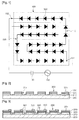
- FIG. 1 is a view showing a structure in which a light emitting diode device is electrically connected with an AC power according to an embodiment
- FIGS. 2 to 9 are sectional views illustrating a light emitting diode device and a method for fabricating the same according to an embodiment.
- FIG. 1 is a view showing a structure in which a light emitting device is electrically connected with an AC power according to an embodiment.
- the light emitting diode device 100 includes a first array block 110 having a plurality of light emitting diode cells 300 serially connected with each other, and a second array block 120 having a plurality of light emitting diode cells 300 serially connected with each other.
- the first and second array blocks 110 and 120 are connected in parallel with each other at first and second nodes 151 and 152 to receive power from the AC power 130 such that the first and second array blocks 110 and 120 can be alternately driven by voltage supplied from the AC power 130.
- the light emitting diode cells 300 in the first array block 110 have polarity arrangement inverse to that of the light emitting diode cells 300 in the second array blocks 120 on the basis of the first and second nodes 151 and 152.
- the number of the light emitting diode cells 300 in the first array block 110 may be identical to the number of the light emitting diode cells 300 in the second array blocks 120. Thus, even if the first and second array blocks 110 and 120 are alternately driven, luminance of light emitted from the light emitting diode device 100 is uniform.
- the light emitting diode cell 300 can be prepared in the form of a light emitting diode.
- the light emitting diode may include a GaN-based semiconductor layer.
- a capacitor 140 can be connected between the light emitting device 100 and the AC power 130 as a passive current limiting device.
- a device such as a resistor or an inductor can also be connected between the light emitting diode device 100 and the AC power 130.
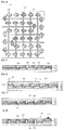
- FIGS. 2 to 9 are sectional views illustrating the light emitting diode device and a method for fabricating the same according to the embodiment.
- a first conductive semiconductor layer 310, an active layer 320, a second conductive semiconductor layer 330 and an ohmic contact layer 331 are se-quentially formed on a substrate 200, and the light emitting diode cells 300 are formed by removing division areas 301.
- the substrate 200 may include a sapphire substrate
- the first conductive semiconductor layer 310 may include a GaN-based semiconductor layer containing N type impurities
- the second conductive semiconductor layer 330 may include a GaN-based semiconductor layer containing P type impurities
- the active layer 320 may include a GaN-based semiconductor layer having a multiple quantum well structure.
- the ohmic contact layer 331 can be selectively formed.
- the embodiment describes a case in which the ohmic contact layer 331 is formed.
- the ohmic contact layer 331 may include an ohmic metal layer, an ohmic metal layer and a reflective metal layer, or a reflective metal layer having superior ohmic characteristics.
- the ohmic contact layer 331 may include an ohmic metal layer including Ni. Further, the ohmic contact layer 331 may be prepared in the form of a multilayer including an ohmic metal layer of Ni and a reflective metal layer containing at least one of Ag, an Ag-based alloy, Pd, Rh, or Pt. Furthermore, the ohmic contact layer 331 may be prepared in the form of a single layer or a multilayer by using a reflective metal layer containing at least one of Ag, an Ag-based alloy, Pd, Rh, or Pt. In addition, the ohmic contact layer 331 may include a transparent metal layer such as ITO (indium tin oxide).
- ITO indium tin oxide
- an etch process of dividing the light emitting diode cells 300 can be performed separately from an etch process of removing the active layer 320, the second conductive semiconductor layer 330 and the ohmic contact layer 331 such that the first conductive semiconductor layer 310 of the light emitting diode cell 300 is exposed.
- a first insulating layer 340 is formed on the substrate 200 including the light emitting diode cells 300, and through holes 341 are formed by selectively etching the first insulating layer 340 such that the first conductive semiconductor layer 310 and the ohmic contact layer 331 are partially exposed.
- the first insulating layer 340 may serve as a passivation layer.
- the first insulating layer 340 is selectively etched to partially expose the first and second conductive semiconductor layers 310 and 330.
- connection layer 400 a metal pattern is formed on the substrate 200 including the light emitting diode cells 300 to form a connection layer 400.
- connection layer 400 may include metal and electrically connects the ohmic contact layer 331 of the light emitting diode cell 300 with the first conductive semiconductor layer 310 of an adjacent light emitting diode cell 300 through the through hole 341.
- the light emitting diode cells 300 are serially connected with each other by the connection layer 400.
- FIG. 4 is a plan view illustrating the light emitting diode device shown in FIG. 3 .
- the light emitting diode cells 300 can be arranged in a matrix type while being spaced apart from each other, and can be electrically isolated by the first insulating layer 340.
- the adjacent light emitting diode cells 300 can be electrically connected with each other by the connection layer 400.
- a second insulating layer 350 is formed on the substrate 200 including the light emitting diode cells 300.
- the second insulating layer 350 planarizes an upper structure of the substrate 200 including the light emitting diode cells 300.
- the second insulating layer 350 isolates the connection layer 400 from a subsequently formed conductive substrate.
- the second insulating layer 350 and the first insulating layer 340 are selectively removed to form a first contact hole 511. Then, a conductive substrate 500 is formed on the second insulating layer 350 including the first contact hole 511.
- the conductive substrate 500 is electrically connected with the light emitting diode cells 300 by a first contact section 510 formed in the first contact hole 511.
- the conductive substrate 500 and the first contact section 510 connected with the conductive substrate 500 can be integrally formed with each other, and the conductive substrate 500 may include metal material.
- the first contact section 510 is electrically connected with the light emitting diode cell 300 by making contact with the ohmic contact layer 331 after passing through the first and second insulating layers 340 and 350. Further, the first contact section 510 can also be electrically connected with the light emitting diode cell 300 by making contact with the connection layer 400 after passing through the second insulating layer 350.
- the first contact section 510 serves as the first node 151 shown in FIG. 1 .
- a plurality of first contact sections 510 may be formed according to a design of the light emitting diode device 100.
- the conductive substrate 500 and the first contact section 510 may be formed on the first contact hole 511 and the second insulating layer 350 through a plating process.
- a seed layer or a bonding metal layer may be formed on the ohmic contact layer 331 and the second insulating layer 350.
- the conductive substrate 500 and the first contact section 510 may be formed through a bonding process.
- the substrate 200 is removed.
- the conductive substrate 500 can support the light emitting diode cells 300 when the substrate 200 is removed.
- the substrate 200 can be separated from the light emitting diode cells 300 by irradiating laser thereto or can be removed through a physical or chemical method.
- a buffer layer or an undoped GaN layer is formed between the substrate 200 and the first conductive semiconductor layer 310, the buffer layer and the undoped GaN layer can be removed together with the substrate 200.
- a second contact section 530 is formed on the first conductive semiconductor layer 310.
- the second contact section 530 serves as the second node 1 52 shown in FIG. 1 .
- a transparent electrode layer 520 is formed on the first conductive semiconductor layer 310.
- the transparent electrode layer 520 may include material having superior electrical conductivity as compared with the first conductive semiconductor layer 310. Thus, current applied to the adjacent light emitting diode cells 300 through the first conductive semiconductor layer 310 can be applied to the transparent electrode layer 520, so that resistance due to the first conductive semiconductor layer 310 can be reduced.
- the transparent electrode layer 520 may include ITO material.
- the second contact section 530 is formed on the light emitting diode cell 300 having no first contact section 510.
- FIG. 9 is a plan view illustrating the light emitting diode device shown in FIG. 8 .
- the first contact section 510 is formed on the light emitting diode cell 300 disposed at the right-most side of the lowermost portion of the light emitting diode device 100 and the second contact section 530 is formed on the light emitting diode cell 300 disposed at the left-most side of the uppermost portion of the light emitting diode device 100 .
- the light emitting diode cells 300 are serially connected with each other, so that the first and second array blocks 110 and 120 are formed.
- the light emitting diode cells 300 included in the first and second array blocks 110 and 120 alternately generate light in response to power through the first and second contact sections 510 and 530.
- the same number of the first and second contact sections 510 and 530 can be formed according to a circuit design of the light emitting diode device 100.
- the first and second contact sections 510 and 530 are electrically connected with the AC power 130 as illustrated in FIG. 1 , so that the light emitting diode cells 300 of the first array block 110 are driven for a half-cycle of a sine wave applied from the AC power 130 and the light emitting diode cells 300 of the second array block 120 are driven for a remaining half-cycle of the sine wave.
- the light emitting diode device can be efficiently driven by the AC power.
- the light emitting diode device package according to the embodiment can be used as a light source for various electronic appliances as well as illumination apparatuses.
Landscapes
- Led Devices (AREA)
- Led Device Packages (AREA)
Claims (9)
- Lichtemittierende Diodenvorrichtung, umfassend:ein leitfähiges Substrat (500);eine Vielzahl lichtemittierender Diodenzellen (300) oberhalb des leitfähigen Substrats (500), wobei jede der lichtemittierenden Diodenzellen eine erste leitfähige Halbleiterschicht (310), eine aktive Schicht (320) und eine zweite leitfähige Halbleiterschicht (330) umfasst, wobei die zweite leitfähige Halbleiterschicht (330), die aktive Schicht (320) und die erste leitfähige Halbleiterschicht (310) vertikal angeordnet sind;eine Verbindungsschicht (400), welche die lichtemittierenden Diodenzellen miteinander elektrisch verbindet;eine Isolierschicht, die zwischen dem leitfähigen Substrat (500) und den lichtemittierende Diodenzellen bereitgestellt ist, wobei die Isolierschicht eine erste Isolierschicht (340), welche die lichtemittierenden Diodenzellen voneinander elektrisch isoliert, und eine zweite Isolierschicht (350), welche den Verbindungsabschnitt (400) vom leitfähigen Substrat (500) elektrisch isoliert, beinhaltet; undeinen zweiten Kontaktabschnitt (530) auf zumindest einer lichtemittierenden Diodenzelle;gekennzeichnet durcheinen ersten Kontaktabschnitt (510), der das leitfähige Substrat (500) direkt mit zumindest einer lichtemittierenden Diodenzelle elektrisch verbindet.
- Lichtemittierende Diodenvorrichtung nach Anspruch 1, wobei der erste Kontaktabschnitt (510) das leitfähige Substrat (500) direkt mit einer unteren Fläche der zweiten leitfähigen Halbleiterschicht (330) zumindest einer lichtemittierenden Diodenzelle elektrisch verbindet; und
auf einer oberen Fläche der ersten leitfähigen Halbleiterschicht (310) zumindest einer lichtemittierenden Diodenzelle ein zweiter Kontaktabschnitt (530) ausgebildet ist. - Lichtemittierende Diodenvorrichtung nach Anspruch 1, wobei die lichtemittierende Diodenzelle auf oder unter der zweiten leitfähigen Halbleiterschicht eine ohmsche Kontaktschicht (331) umfasst.
- Lichtemittierende Diodenvorrichtung nach Anspruch 1, wobei die Verbindungsschicht die erste leitfähige Halbleiterschicht der lichtemittierenden Diodenzelle mit einer zweiten leitfähigen Halbleiterschicht einer benachbarten lichtemittierenden Diodenzelle elektrisch verbindet.
- Lichtemittierende Diodenvorrichtung nach Anspruch 2, wobei der erste Kontaktabschnitt das leitfähige Substrat mit der zweiten leitfähigen Halbleiterschicht elektrisch verbindet und der zweite Kontaktabschnitt mit der ersten leitfähigen Halbleiterschicht elektrisch verbunden ist.
- Lichtemittierende Diodenvorrichtung nach Anspruch 1, umfassend eine transparente Elektrodenschicht (520) auf der ersten leitfähigen Halbleiterschicht, wobei der zweite Kontaktabschnitt auf der transparenten Elektrodenschicht ausgebildet ist.
- Lichtemittierende Diodenvorrichtung nach Anspruch 3, wobei die ohmsche Kontaktschicht zumindest eine ohmsche Metallschicht und/oder eine reflektierende Metallschicht umfasst.
- Verfahren zur Herstellung einer lichtemittierenden Diodenvorrichtung, umfassend folgende Schritte:Ausbilden einer ersten leitfähigen Halbleiterschicht (310), einer aktiven Schicht (320) und einer zweiten leitfähigen Halbleiterschicht (330) auf einem leitfähigen Substrat (500);Ausbilden einer Vielzahl lichtemittierender Diodenzellen durch selektives Entfernen der ersten leitfähigen Halbleiterschicht, der aktiven Schicht und der zweiten leitfähigen Halbleiterschicht;Ausbilden einer ersten Isolierschicht (340) auf den lichtemittierenden Diodenzellen, um die erste und zweite leitfähige Halbleiterschicht teilweise freizulegen;Ausbilden einer Verbindungsschicht (400), welche die erste leitfähige Halbleiterschicht mit der zweiten leitfähigen Halbleiterschicht elektrisch verbindet, sodass die lichtemittierenden Diodenzellen miteinander elektrisch verbunden sind;Ausbilden einer zweiten Isolierschicht (350) auf der ersten Isolierschicht, der lichtemittierenden Diodenzellen und der Verbindungsschicht, um die lichtemittierende Diodenzellen teilweise freizulegen;Ausbilden eines ersten Kontaktlochs durch selektives Entfernen der zweiten Isolierschicht;Ausbilden eines ersten Kontaktabschnitts (510) im ersten Kontaktloch und Ausbilden eines leitfähigen Substrats auf der zweiten Isolierschicht undEntfernen des Substrats und Ausbilden eines zweiten Kontaktabschnitts (530), der mit zumindest einer lichtemittierenden Diodenzelle elektrisch verbunden ist.
- Verfahren zum Herstellen der lichtemittierenden Diodenvorrichtung nach Anspruch 8, wobei die zweite leitfähige Halbleiterschicht, die aktive Schicht und die erste leitfähige Halbleiterschicht vertikal angeordnet sind, der erste Kontaktabschnitt mit der zweiten leitfähigen Halbleiterschicht elektrisch verbunden ist und der zweite Kontaktabschnitt mit der ersten leitfähigen Halbleiterschicht elektrisch verbunden ist.
Applications Claiming Priority (2)
| Application Number | Priority Date | Filing Date | Title |
|---|---|---|---|
| KR1020070103561A KR100928259B1 (ko) | 2007-10-15 | 2007-10-15 | 발광 장치 및 그 제조방법 |
| PCT/KR2008/006023 WO2009051376A2 (en) | 2007-10-15 | 2008-10-13 | Light emitting device and method for fabricating the same |
Publications (3)
| Publication Number | Publication Date |
|---|---|
| EP2201616A2 EP2201616A2 (de) | 2010-06-30 |
| EP2201616A4 EP2201616A4 (de) | 2011-01-19 |
| EP2201616B1 true EP2201616B1 (de) | 2013-12-04 |
Family
ID=40567934
Family Applications (1)
| Application Number | Title | Priority Date | Filing Date |
|---|---|---|---|
| EP08838586.9A Not-in-force EP2201616B1 (de) | 2007-10-15 | 2008-10-13 | Lichtemittierende diodenvorrichtung und verfahren zu ihrer herstellung |
Country Status (5)
| Country | Link |
|---|---|
| US (2) | US8299477B2 (de) |
| EP (1) | EP2201616B1 (de) |
| KR (1) | KR100928259B1 (de) |
| CN (1) | CN101828270B (de) |
| WO (1) | WO2009051376A2 (de) |
Families Citing this family (21)
| Publication number | Priority date | Publication date | Assignee | Title |
|---|---|---|---|---|
| KR100986570B1 (ko) | 2009-08-31 | 2010-10-07 | 엘지이노텍 주식회사 | 반도체 발광소자 및 그 제조방법 |
| US20110049469A1 (en) * | 2009-09-03 | 2011-03-03 | Rajaram Bhat | Enhanced P-Contacts For Light Emitting Devices |
| KR101482050B1 (ko) * | 2010-02-04 | 2015-01-13 | 에피스타 코포레이션 | 발광다이오드 어레이 |
| KR101601624B1 (ko) * | 2010-02-19 | 2016-03-09 | 삼성전자주식회사 | 멀티셀 어레이를 갖는 반도체 발광장치, 발광모듈 및 조명장치 |
| CN102097562A (zh) * | 2010-12-14 | 2011-06-15 | 金木子 | 交流表面贴片式垂直结构半导体发光二极管 |
| KR101115539B1 (ko) | 2011-06-10 | 2012-02-28 | 서울옵토디바이스주식회사 | 발광 소자 및 그것을 제조하는 방법 |
| KR20130021300A (ko) * | 2011-08-22 | 2013-03-05 | 엘지이노텍 주식회사 | 발광소자, 발광소자 패키지, 및 라이트 유닛 |
| FR2992465B1 (fr) * | 2012-06-22 | 2015-03-20 | Soitec Silicon On Insulator | Procede de fabrication collective de leds et structure pour la fabrication collective de leds |
| US8933433B2 (en) * | 2012-07-30 | 2015-01-13 | LuxVue Technology Corporation | Method and structure for receiving a micro device |
| CN103579431A (zh) * | 2012-08-07 | 2014-02-12 | 华夏光股份有限公司 | 半导体发光结构及其制造方法 |
| CN103681725A (zh) * | 2012-09-11 | 2014-03-26 | 旭明光电股份有限公司 | 发光二极管 |
| KR20140059985A (ko) * | 2012-11-09 | 2014-05-19 | 엘지이노텍 주식회사 | 발광소자 |
| KR101992366B1 (ko) * | 2012-12-27 | 2019-06-24 | 엘지이노텍 주식회사 | 발광 소자 |
| DE102014101896A1 (de) * | 2014-02-14 | 2015-08-20 | Osram Opto Semiconductors Gmbh | Verfahren zur Herstellung eines optoelektronischen Halbleiterbauteils sowie optoelektronisches Halbleiterbauteil |
| KR20150105255A (ko) | 2014-03-06 | 2015-09-16 | 에피스타 코포레이션 | 발광 소자 |
| US10910350B2 (en) * | 2014-05-24 | 2021-02-02 | Hiphoton Co., Ltd. | Structure of a semiconductor array |
| KR102480220B1 (ko) | 2016-04-08 | 2022-12-26 | 삼성전자주식회사 | 발광 다이오드 모듈 및 이를 구비한 디스플레이 패널 |
| CN110224049A (zh) * | 2019-05-31 | 2019-09-10 | 深圳市华星光电半导体显示技术有限公司 | micro LED芯片及其制备方法 |
| JP7014973B2 (ja) * | 2019-08-28 | 2022-02-02 | 日亜化学工業株式会社 | 発光装置 |
| US11508891B2 (en) * | 2020-01-31 | 2022-11-22 | Nichia Corporation | Method of manufacturing light-emitting module |
| CN114823771B (zh) * | 2021-04-20 | 2025-02-07 | 友达光电股份有限公司 | 半导体装置以及显示装置 |
Family Cites Families (17)
| Publication number | Priority date | Publication date | Assignee | Title |
|---|---|---|---|---|
| EP2270875B1 (de) | 2000-04-26 | 2018-01-10 | OSRAM Opto Semiconductors GmbH | Strahlungsmittierendes Halbleiterbauelement und dessen Herstellungsverfahren |
| JP3822545B2 (ja) | 2002-04-12 | 2006-09-20 | 士郎 酒井 | 発光装置 |
| EP1892764B1 (de) | 2002-08-29 | 2016-03-09 | Seoul Semiconductor Co., Ltd. | Lichtemittierende Vorrichtung mit Leuchtdioden |
| JP2004273746A (ja) * | 2003-03-07 | 2004-09-30 | Hitachi Cable Ltd | 発光ダイオードアレイ |
| EP1649514B1 (de) * | 2003-07-30 | 2014-01-01 | Panasonic Corporation | Licht emittierendes halbleiterbauelement, licht emittierendes modul und beleuchtungsvorrichtung |
| US7675075B2 (en) * | 2003-08-28 | 2010-03-09 | Panasonic Corporation | Semiconductor light emitting device, light emitting module, lighting apparatus, display element and manufacturing method of semiconductor light emitting device |
| TWI223460B (en) * | 2003-09-23 | 2004-11-01 | United Epitaxy Co Ltd | Light emitting diodes in series connection and method of making the same |
| WO2005062389A2 (en) * | 2003-12-24 | 2005-07-07 | Matsushita Electric Industrial Co., Ltd. | Semiconductor light emitting device, lighting module, lighting apparatus, display element, and manufacturing method for semiconductor light emitting device |
| KR100867515B1 (ko) * | 2004-12-06 | 2008-11-07 | 삼성전기주식회사 | 발광소자 패키지 |
| WO2006098545A2 (en) * | 2004-12-14 | 2006-09-21 | Seoul Opto Device Co., Ltd. | Light emitting device having a plurality of light emitting cells and package mounting the same |
| TWI374553B (en) * | 2004-12-22 | 2012-10-11 | Panasonic Corp | Semiconductor light emitting device, illumination module, illumination apparatus, method for manufacturing semiconductor light emitting device, and method for manufacturing semiconductor light emitting element |
| KR100631129B1 (ko) | 2005-03-29 | 2006-10-02 | 삼성전기주식회사 | 수직구조 질화갈륨계 발광다이오드 소자의 제조방법 |
| KR20060121454A (ko) * | 2005-05-24 | 2006-11-29 | 엘지전자 주식회사 | 발광소자 어레이 제조방법 |
| JP2008544540A (ja) * | 2005-06-22 | 2008-12-04 | ソウル オプト デバイス カンパニー リミテッド | 発光素子及びその製造方法 |
| JP5010129B2 (ja) * | 2005-09-30 | 2012-08-29 | 株式会社東芝 | 発光ダイオード及びその製造方法 |
| KR101171356B1 (ko) * | 2005-11-01 | 2012-08-09 | 서울옵토디바이스주식회사 | 다수의 셀이 결합된 발광 소자 및 이의 제조 방법 |
| WO2008091837A2 (en) * | 2007-01-22 | 2008-07-31 | Cree Led Lighting Solutions, Inc. | Fault tolerant light emitters, systems incorporating fault tolerant light emitters and methods of fabricating fault tolerant light emitters |
-
2007
- 2007-10-15 KR KR1020070103561A patent/KR100928259B1/ko not_active Expired - Fee Related
-
2008
- 2008-10-13 CN CN2008801116385A patent/CN101828270B/zh not_active Expired - Fee Related
- 2008-10-13 EP EP08838586.9A patent/EP2201616B1/de not_active Not-in-force
- 2008-10-13 WO PCT/KR2008/006023 patent/WO2009051376A2/en not_active Ceased
- 2008-10-13 US US12/738,051 patent/US8299477B2/en active Active
-
2012
- 2012-10-12 US US13/651,031 patent/US9893118B2/en active Active
Also Published As
| Publication number | Publication date |
|---|---|
| EP2201616A2 (de) | 2010-06-30 |
| CN101828270B (zh) | 2012-01-18 |
| US9893118B2 (en) | 2018-02-13 |
| KR100928259B1 (ko) | 2009-11-24 |
| KR20090038193A (ko) | 2009-04-20 |
| US8299477B2 (en) | 2012-10-30 |
| US20130037836A1 (en) | 2013-02-14 |
| CN101828270A (zh) | 2010-09-08 |
| WO2009051376A3 (en) | 2009-07-16 |
| US20100219432A1 (en) | 2010-09-02 |
| EP2201616A4 (de) | 2011-01-19 |
| WO2009051376A2 (en) | 2009-04-23 |
Similar Documents
| Publication | Publication Date | Title |
|---|---|---|
| EP2201616B1 (de) | Lichtemittierende diodenvorrichtung und verfahren zu ihrer herstellung | |
| US8492775B2 (en) | Light emitting element with a plurality of cells bonded, method of manufacturing the same, and light emitting device using the same | |
| EP1935038B1 (de) | Lichtemissionsvorrichtung mit vertikal gestapelten lichtemissionsdioden | |
| US9461091B2 (en) | Light emitting diode | |
| US9368548B2 (en) | AC light emitting diode and method for fabricating the same | |
| US8129917B2 (en) | Light emitting device for AC operation | |
| US8450765B2 (en) | Light emitting diode chip and method for manufacturing the same | |
| KR101597326B1 (ko) | 복수개의 발광셀들을 갖는 발광 소자 | |
| TW201203611A (en) | Light emitting device and its manufacturing method | |
| KR20070063977A (ko) | 다수의 발광 셀이 어레이된 발광 소자 | |
| KR20060037589A (ko) | 다수의 셀이 결합된 발광 소자 및 이의 제조 방법 및 이를이용한 발광 장치 | |
| KR20100047795A (ko) | 발광 다이오드 | |
| KR100637652B1 (ko) | 전원 극성에 관계없이 작동하는 발광다이오드 및 그제조방법 | |
| CN101866894B (zh) | 电极结构及其发光元件 | |
| KR20070062731A (ko) | 다수개의 발광 셀이 어레이된 발광 소자 |
Legal Events
| Date | Code | Title | Description |
|---|---|---|---|
| PUAI | Public reference made under article 153(3) epc to a published international application that has entered the european phase |
Free format text: ORIGINAL CODE: 0009012 |
|
| 17P | Request for examination filed |
Effective date: 20100427 |
|
| AK | Designated contracting states |
Kind code of ref document: A2 Designated state(s): AT BE BG CH CY CZ DE DK EE ES FI FR GB GR HR HU IE IS IT LI LT LU LV MC MT NL NO PL PT RO SE SI SK TR |
|
| AX | Request for extension of the european patent |
Extension state: AL BA MK RS |
|
| RAP1 | Party data changed (applicant data changed or rights of an application transferred) |
Owner name: LG INNOTEK CO., LTD. |
|
| A4 | Supplementary search report drawn up and despatched |
Effective date: 20101222 |
|
| RIC1 | Information provided on ipc code assigned before grant |
Ipc: H01L 27/15 20060101AFI20101216BHEP |
|
| DAX | Request for extension of the european patent (deleted) | ||
| REG | Reference to a national code |
Ref country code: DE Ref legal event code: R079 Ref document number: 602008029138 Country of ref document: DE Free format text: PREVIOUS MAIN CLASS: H01L0033000000 Ipc: H01L0027150000 |
|
| GRAP | Despatch of communication of intention to grant a patent |
Free format text: ORIGINAL CODE: EPIDOSNIGR1 |
|
| RIC1 | Information provided on ipc code assigned before grant |
Ipc: H01L 33/00 20100101ALN20130523BHEP Ipc: H01L 33/62 20100101ALN20130523BHEP Ipc: H01L 27/15 20060101AFI20130523BHEP Ipc: H01L 33/38 20100101ALN20130523BHEP |
|
| INTG | Intention to grant announced |
Effective date: 20130613 |
|
| GRAS | Grant fee paid |
Free format text: ORIGINAL CODE: EPIDOSNIGR3 |
|
| GRAA | (expected) grant |
Free format text: ORIGINAL CODE: 0009210 |
|
| AK | Designated contracting states |
Kind code of ref document: B1 Designated state(s): AT BE BG CH CY CZ DE DK EE ES FI FR GB GR HR HU IE IS IT LI LT LU LV MC MT NL NO PL PT RO SE SI SK TR |
|
| REG | Reference to a national code |
Ref country code: GB Ref legal event code: FG4D |
|
| REG | Reference to a national code |
Ref country code: CH Ref legal event code: EP |
|
| REG | Reference to a national code |
Ref country code: AT Ref legal event code: REF Ref document number: 643831 Country of ref document: AT Kind code of ref document: T Effective date: 20140115 Ref country code: IE Ref legal event code: FG4D |
|
| REG | Reference to a national code |
Ref country code: DE Ref legal event code: R096 Ref document number: 602008029138 Country of ref document: DE Effective date: 20140130 |
|
| REG | Reference to a national code |
Ref country code: NL Ref legal event code: T3 |
|
| REG | Reference to a national code |
Ref country code: AT Ref legal event code: MK05 Ref document number: 643831 Country of ref document: AT Kind code of ref document: T Effective date: 20131204 |
|
| PG25 | Lapsed in a contracting state [announced via postgrant information from national office to epo] |
Ref country code: FI Free format text: LAPSE BECAUSE OF FAILURE TO SUBMIT A TRANSLATION OF THE DESCRIPTION OR TO PAY THE FEE WITHIN THE PRESCRIBED TIME-LIMIT Effective date: 20131204 Ref country code: SE Free format text: LAPSE BECAUSE OF FAILURE TO SUBMIT A TRANSLATION OF THE DESCRIPTION OR TO PAY THE FEE WITHIN THE PRESCRIBED TIME-LIMIT Effective date: 20131204 Ref country code: HR Free format text: LAPSE BECAUSE OF FAILURE TO SUBMIT A TRANSLATION OF THE DESCRIPTION OR TO PAY THE FEE WITHIN THE PRESCRIBED TIME-LIMIT Effective date: 20131204 Ref country code: NO Free format text: LAPSE BECAUSE OF FAILURE TO SUBMIT A TRANSLATION OF THE DESCRIPTION OR TO PAY THE FEE WITHIN THE PRESCRIBED TIME-LIMIT Effective date: 20140304 Ref country code: LT Free format text: LAPSE BECAUSE OF FAILURE TO SUBMIT A TRANSLATION OF THE DESCRIPTION OR TO PAY THE FEE WITHIN THE PRESCRIBED TIME-LIMIT Effective date: 20131204 |
|
| REG | Reference to a national code |
Ref country code: LT Ref legal event code: MG4D |
|
| PG25 | Lapsed in a contracting state [announced via postgrant information from national office to epo] |
Ref country code: AT Free format text: LAPSE BECAUSE OF FAILURE TO SUBMIT A TRANSLATION OF THE DESCRIPTION OR TO PAY THE FEE WITHIN THE PRESCRIBED TIME-LIMIT Effective date: 20131204 Ref country code: LV Free format text: LAPSE BECAUSE OF FAILURE TO SUBMIT A TRANSLATION OF THE DESCRIPTION OR TO PAY THE FEE WITHIN THE PRESCRIBED TIME-LIMIT Effective date: 20131204 Ref country code: CY Free format text: LAPSE BECAUSE OF FAILURE TO SUBMIT A TRANSLATION OF THE DESCRIPTION OR TO PAY THE FEE WITHIN THE PRESCRIBED TIME-LIMIT Effective date: 20131204 |
|
| PG25 | Lapsed in a contracting state [announced via postgrant information from national office to epo] |
Ref country code: BE Free format text: LAPSE BECAUSE OF FAILURE TO SUBMIT A TRANSLATION OF THE DESCRIPTION OR TO PAY THE FEE WITHIN THE PRESCRIBED TIME-LIMIT Effective date: 20131204 Ref country code: IS Free format text: LAPSE BECAUSE OF FAILURE TO SUBMIT A TRANSLATION OF THE DESCRIPTION OR TO PAY THE FEE WITHIN THE PRESCRIBED TIME-LIMIT Effective date: 20140404 Ref country code: EE Free format text: LAPSE BECAUSE OF FAILURE TO SUBMIT A TRANSLATION OF THE DESCRIPTION OR TO PAY THE FEE WITHIN THE PRESCRIBED TIME-LIMIT Effective date: 20131204 |
|
| PG25 | Lapsed in a contracting state [announced via postgrant information from national office to epo] |
Ref country code: ES Free format text: LAPSE BECAUSE OF FAILURE TO SUBMIT A TRANSLATION OF THE DESCRIPTION OR TO PAY THE FEE WITHIN THE PRESCRIBED TIME-LIMIT Effective date: 20131204 Ref country code: PT Free format text: LAPSE BECAUSE OF FAILURE TO SUBMIT A TRANSLATION OF THE DESCRIPTION OR TO PAY THE FEE WITHIN THE PRESCRIBED TIME-LIMIT Effective date: 20140404 Ref country code: PL Free format text: LAPSE BECAUSE OF FAILURE TO SUBMIT A TRANSLATION OF THE DESCRIPTION OR TO PAY THE FEE WITHIN THE PRESCRIBED TIME-LIMIT Effective date: 20131204 Ref country code: SK Free format text: LAPSE BECAUSE OF FAILURE TO SUBMIT A TRANSLATION OF THE DESCRIPTION OR TO PAY THE FEE WITHIN THE PRESCRIBED TIME-LIMIT Effective date: 20131204 Ref country code: CZ Free format text: LAPSE BECAUSE OF FAILURE TO SUBMIT A TRANSLATION OF THE DESCRIPTION OR TO PAY THE FEE WITHIN THE PRESCRIBED TIME-LIMIT Effective date: 20131204 Ref country code: RO Free format text: LAPSE BECAUSE OF FAILURE TO SUBMIT A TRANSLATION OF THE DESCRIPTION OR TO PAY THE FEE WITHIN THE PRESCRIBED TIME-LIMIT Effective date: 20131204 |
|
| REG | Reference to a national code |
Ref country code: DE Ref legal event code: R097 Ref document number: 602008029138 Country of ref document: DE |
|
| PLBE | No opposition filed within time limit |
Free format text: ORIGINAL CODE: 0009261 |
|
| STAA | Information on the status of an ep patent application or granted ep patent |
Free format text: STATUS: NO OPPOSITION FILED WITHIN TIME LIMIT |
|
| PG25 | Lapsed in a contracting state [announced via postgrant information from national office to epo] |
Ref country code: DK Free format text: LAPSE BECAUSE OF FAILURE TO SUBMIT A TRANSLATION OF THE DESCRIPTION OR TO PAY THE FEE WITHIN THE PRESCRIBED TIME-LIMIT Effective date: 20131204 |
|
| 26N | No opposition filed |
Effective date: 20140905 |
|
| REG | Reference to a national code |
Ref country code: DE Ref legal event code: R097 Ref document number: 602008029138 Country of ref document: DE Effective date: 20140905 |
|
| PG25 | Lapsed in a contracting state [announced via postgrant information from national office to epo] |
Ref country code: SI Free format text: LAPSE BECAUSE OF FAILURE TO SUBMIT A TRANSLATION OF THE DESCRIPTION OR TO PAY THE FEE WITHIN THE PRESCRIBED TIME-LIMIT Effective date: 20131204 |
|
| PG25 | Lapsed in a contracting state [announced via postgrant information from national office to epo] |
Ref country code: MC Free format text: LAPSE BECAUSE OF FAILURE TO SUBMIT A TRANSLATION OF THE DESCRIPTION OR TO PAY THE FEE WITHIN THE PRESCRIBED TIME-LIMIT Effective date: 20131204 Ref country code: LU Free format text: LAPSE BECAUSE OF FAILURE TO SUBMIT A TRANSLATION OF THE DESCRIPTION OR TO PAY THE FEE WITHIN THE PRESCRIBED TIME-LIMIT Effective date: 20141013 |
|
| REG | Reference to a national code |
Ref country code: CH Ref legal event code: PL |
|
| REG | Reference to a national code |
Ref country code: IE Ref legal event code: MM4A |
|
| PG25 | Lapsed in a contracting state [announced via postgrant information from national office to epo] |
Ref country code: CH Free format text: LAPSE BECAUSE OF NON-PAYMENT OF DUE FEES Effective date: 20141031 Ref country code: LI Free format text: LAPSE BECAUSE OF NON-PAYMENT OF DUE FEES Effective date: 20141031 |
|
| PG25 | Lapsed in a contracting state [announced via postgrant information from national office to epo] |
Ref country code: IT Free format text: LAPSE BECAUSE OF FAILURE TO SUBMIT A TRANSLATION OF THE DESCRIPTION OR TO PAY THE FEE WITHIN THE PRESCRIBED TIME-LIMIT Effective date: 20131204 |
|
| REG | Reference to a national code |
Ref country code: FR Ref legal event code: PLFP Year of fee payment: 8 |
|
| PG25 | Lapsed in a contracting state [announced via postgrant information from national office to epo] |
Ref country code: IE Free format text: LAPSE BECAUSE OF NON-PAYMENT OF DUE FEES Effective date: 20141013 |
|
| PG25 | Lapsed in a contracting state [announced via postgrant information from national office to epo] |
Ref country code: BG Free format text: LAPSE BECAUSE OF FAILURE TO SUBMIT A TRANSLATION OF THE DESCRIPTION OR TO PAY THE FEE WITHIN THE PRESCRIBED TIME-LIMIT Effective date: 20131204 |
|
| PG25 | Lapsed in a contracting state [announced via postgrant information from national office to epo] |
Ref country code: GR Free format text: LAPSE BECAUSE OF FAILURE TO SUBMIT A TRANSLATION OF THE DESCRIPTION OR TO PAY THE FEE WITHIN THE PRESCRIBED TIME-LIMIT Effective date: 20140305 |
|
| PG25 | Lapsed in a contracting state [announced via postgrant information from national office to epo] |
Ref country code: TR Free format text: LAPSE BECAUSE OF FAILURE TO SUBMIT A TRANSLATION OF THE DESCRIPTION OR TO PAY THE FEE WITHIN THE PRESCRIBED TIME-LIMIT Effective date: 20131204 Ref country code: HU Free format text: LAPSE BECAUSE OF FAILURE TO SUBMIT A TRANSLATION OF THE DESCRIPTION OR TO PAY THE FEE WITHIN THE PRESCRIBED TIME-LIMIT; INVALID AB INITIO Effective date: 20081013 Ref country code: MT Free format text: LAPSE BECAUSE OF FAILURE TO SUBMIT A TRANSLATION OF THE DESCRIPTION OR TO PAY THE FEE WITHIN THE PRESCRIBED TIME-LIMIT Effective date: 20131204 |
|
| REG | Reference to a national code |
Ref country code: FR Ref legal event code: PLFP Year of fee payment: 9 |
|
| PGFP | Annual fee paid to national office [announced via postgrant information from national office to epo] |
Ref country code: GB Payment date: 20160908 Year of fee payment: 9 Ref country code: NL Payment date: 20160908 Year of fee payment: 9 |
|
| PGFP | Annual fee paid to national office [announced via postgrant information from national office to epo] |
Ref country code: FR Payment date: 20160912 Year of fee payment: 9 |
|
| REG | Reference to a national code |
Ref country code: NL Ref legal event code: MM Effective date: 20171101 |
|
| GBPC | Gb: european patent ceased through non-payment of renewal fee |
Effective date: 20171013 |
|
| REG | Reference to a national code |
Ref country code: FR Ref legal event code: ST Effective date: 20180629 |
|
| PG25 | Lapsed in a contracting state [announced via postgrant information from national office to epo] |
Ref country code: GB Free format text: LAPSE BECAUSE OF NON-PAYMENT OF DUE FEES Effective date: 20171013 Ref country code: NL Free format text: LAPSE BECAUSE OF NON-PAYMENT OF DUE FEES Effective date: 20171101 |
|
| PG25 | Lapsed in a contracting state [announced via postgrant information from national office to epo] |
Ref country code: FR Free format text: LAPSE BECAUSE OF NON-PAYMENT OF DUE FEES Effective date: 20171031 |
|
| REG | Reference to a national code |
Ref country code: DE Ref legal event code: R081 Ref document number: 602008029138 Country of ref document: DE Owner name: SUZHOU LEKIN SEMICONDUCTOR CO. LTD., TAICANG, CN Free format text: FORMER OWNER: LG INNOTEK CO., LTD., SEOUL, KR |
|
| PGFP | Annual fee paid to national office [announced via postgrant information from national office to epo] |
Ref country code: DE Payment date: 20230906 Year of fee payment: 16 |
|
| REG | Reference to a national code |
Ref country code: DE Ref legal event code: R079 Ref document number: 602008029138 Country of ref document: DE Free format text: PREVIOUS MAIN CLASS: H01L0027150000 Ipc: H10H0029140000 |
|
| REG | Reference to a national code |
Ref country code: DE Ref legal event code: R119 Ref document number: 602008029138 Country of ref document: DE |
|
| PG25 | Lapsed in a contracting state [announced via postgrant information from national office to epo] |
Ref country code: DE Free format text: LAPSE BECAUSE OF NON-PAYMENT OF DUE FEES Effective date: 20250501 |