EP2201596B1 - Hochdruckentladungslampe - Google Patents
Hochdruckentladungslampe Download PDFInfo
- Publication number
- EP2201596B1 EP2201596B1 EP08803097A EP08803097A EP2201596B1 EP 2201596 B1 EP2201596 B1 EP 2201596B1 EP 08803097 A EP08803097 A EP 08803097A EP 08803097 A EP08803097 A EP 08803097A EP 2201596 B1 EP2201596 B1 EP 2201596B1
- Authority
- EP
- European Patent Office
- Prior art keywords
- discharge lamp
- pressure discharge
- ring structure
- discharge vessel
- cooling
- Prior art date
- Legal status (The legal status is an assumption and is not a legal conclusion. Google has not performed a legal analysis and makes no representation as to the accuracy of the status listed.)
- Not-in-force
Links
- 239000000919 ceramic Substances 0.000 claims description 15
- 238000000576 coating method Methods 0.000 claims description 11
- 239000011248 coating agent Substances 0.000 claims description 9
- 229910001507 metal halide Inorganic materials 0.000 claims description 9
- 150000005309 metal halides Chemical class 0.000 claims description 9
- 230000005855 radiation Effects 0.000 claims description 7
- 239000002253 acid Substances 0.000 claims 1
- 238000001816 cooling Methods 0.000 description 43
- 230000000694 effects Effects 0.000 description 10
- OKTJSMMVPCPJKN-UHFFFAOYSA-N Carbon Chemical compound [C] OKTJSMMVPCPJKN-UHFFFAOYSA-N 0.000 description 8
- 239000000463 material Substances 0.000 description 5
- 229910052799 carbon Inorganic materials 0.000 description 4
- 229910002804 graphite Inorganic materials 0.000 description 4
- 239000010439 graphite Substances 0.000 description 4
- 239000000203 mixture Substances 0.000 description 4
- 238000009826 distribution Methods 0.000 description 3
- 238000004519 manufacturing process Methods 0.000 description 3
- 229910052751 metal Inorganic materials 0.000 description 3
- 239000002184 metal Substances 0.000 description 3
- 239000011734 sodium Substances 0.000 description 3
- 230000001419 dependent effect Effects 0.000 description 2
- 238000004821 distillation Methods 0.000 description 2
- 150000004820 halides Chemical class 0.000 description 2
- 150000002739 metals Chemical class 0.000 description 2
- 238000011017 operating method Methods 0.000 description 2
- 238000009877 rendering Methods 0.000 description 2
- 239000007787 solid Substances 0.000 description 2
- 239000000243 solution Substances 0.000 description 2
- 230000007704 transition Effects 0.000 description 2
- 229910018072 Al 2 O 3 Inorganic materials 0.000 description 1
- 229910052684 Cerium Inorganic materials 0.000 description 1
- DGAQECJNVWCQMB-PUAWFVPOSA-M Ilexoside XXIX Chemical compound C[C@@H]1CC[C@@]2(CC[C@@]3(C(=CC[C@H]4[C@]3(CC[C@@H]5[C@@]4(CC[C@@H](C5(C)C)OS(=O)(=O)[O-])C)C)[C@@H]2[C@]1(C)O)C)C(=O)O[C@H]6[C@@H]([C@H]([C@@H]([C@H](O6)CO)O)O)O.[Na+] DGAQECJNVWCQMB-PUAWFVPOSA-M 0.000 description 1
- 229910052779 Neodymium Inorganic materials 0.000 description 1
- 229910052777 Praseodymium Inorganic materials 0.000 description 1
- 239000000853 adhesive Substances 0.000 description 1
- 230000001070 adhesive effect Effects 0.000 description 1
- 230000002411 adverse Effects 0.000 description 1
- 229910052782 aluminium Inorganic materials 0.000 description 1
- XAGFODPZIPBFFR-UHFFFAOYSA-N aluminium Chemical compound [Al] XAGFODPZIPBFFR-UHFFFAOYSA-N 0.000 description 1
- 230000004323 axial length Effects 0.000 description 1
- 230000015572 biosynthetic process Effects 0.000 description 1
- 239000004568 cement Substances 0.000 description 1
- 229910010293 ceramic material Inorganic materials 0.000 description 1
- 239000011195 cermet Substances 0.000 description 1
- 238000009833 condensation Methods 0.000 description 1
- 230000005494 condensation Effects 0.000 description 1
- 238000010276 construction Methods 0.000 description 1
- 239000006185 dispersion Substances 0.000 description 1
- 230000005284 excitation Effects 0.000 description 1
- 238000005755 formation reaction Methods 0.000 description 1
- 229910052735 hafnium Inorganic materials 0.000 description 1
- 230000017525 heat dissipation Effects 0.000 description 1
- 238000001746 injection moulding Methods 0.000 description 1
- 150000001247 metal acetylides Chemical class 0.000 description 1
- 238000000034 method Methods 0.000 description 1
- 238000012986 modification Methods 0.000 description 1
- 230000004048 modification Effects 0.000 description 1
- 238000007789 sealing Methods 0.000 description 1
- 238000005204 segregation Methods 0.000 description 1
- 238000007569 slipcasting Methods 0.000 description 1
- 229910052708 sodium Inorganic materials 0.000 description 1
- 230000001629 suppression Effects 0.000 description 1
- 229910052715 tantalum Inorganic materials 0.000 description 1
- 229910052719 titanium Inorganic materials 0.000 description 1
- 229910052726 zirconium Inorganic materials 0.000 description 1
Images


Classifications
-
- H—ELECTRICITY
- H01—ELECTRIC ELEMENTS
- H01J—ELECTRIC DISCHARGE TUBES OR DISCHARGE LAMPS
- H01J61/00—Gas-discharge or vapour-discharge lamps
- H01J61/02—Details
- H01J61/52—Cooling arrangements; Heating arrangements; Means for circulating gas or vapour within the discharge space
- H01J61/523—Heating or cooling particular parts of the lamp
-
- H—ELECTRICITY
- H01—ELECTRIC ELEMENTS
- H01J—ELECTRIC DISCHARGE TUBES OR DISCHARGE LAMPS
- H01J61/00—Gas-discharge or vapour-discharge lamps
- H01J61/02—Details
- H01J61/30—Vessels; Containers
-
- H—ELECTRICITY
- H01—ELECTRIC ELEMENTS
- H01J—ELECTRIC DISCHARGE TUBES OR DISCHARGE LAMPS
- H01J61/00—Gas-discharge or vapour-discharge lamps
- H01J61/82—Lamps with high-pressure unconstricted discharge having a cold pressure > 400 Torr
- H01J61/827—Metal halide arc lamps
Definitions
- the invention relates to a high-pressure discharge lamp according to the preamble of claim 1.
- Such lamps are in particular high-pressure discharge lamps with a ceramic discharge vessel for general lighting.
- the US Pat. No. 4,970,431 discloses a sodium high-pressure discharge lamp in which the bulb of the discharge vessel is made of ceramic. At the cylindrical ends of the discharge vessel fin-like extensions are attached, which are used for heat dissipation.
- a metal halide lamps according to overbegriffs of claim 1 is to the US-A-2005/184632 known.
- the object of the present invention is to provide a high-pressure discharge lamp whose color spread is significantly reduced compared to previous lamps.
- the high pressure discharge lamp is equipped with a ceramic elongate discharge vessel.
- the discharge vessel defines a lamp axis and has a central portion and two end portions, each sealed by seals, with electrodes anchored in the seals extending into the discharge volume enveloped by the discharge vessel, and a charge containing metal halides in the discharge volume is housed.
- at least one end region is seated in an annular structure which, at least as far as its basic body is concerned, extends outwardly in a substantially axis-parallel manner and is spaced from the seal.
- the seals are capillaries.
- the invention relates in particular to lamps with an increased aspect ratio, or else lamps which have shortened structures for the seals.
- the end region preferably has a tapering inner contour in the electrode rear space. That is, the central part of the discharge vessel has a maximum or constant inner diameter ID and the end regions have a smaller inner diameter.
- the ring structure is preferably formed concentrically outside the electrode construction or the seal at the end region.
- the discharge vessel is typically made of aluminum-containing ceramics such as PCA or YAG, AlN, or AlY03.
- a freestanding, seal-spaced cooling structure is used, which is itself formed of ceramic and, in particular, may be an integral part of the end region.
- it may also be a separate component, according to the invention extinct translucent Ceramics such as Al 2 O 3 or AlN, alternatively, for example, from steatite.
- the separate component is attached by means of cement or adhesive to the end of the discharge vessel.
- the invention is particularly suitable for highly loaded metal halide lamps in which the ratio between the inner length IL and the maximum inner diameter ID of the discharge vessel, the so-called aspect ratio IL / ID, is between 1.5 and 8.
- the temperature gradient of highly loaded burners which typically achieve a wall load of at least 30 W / cm 2 in the axial length between the electrodes, can be selected by choosing the starting point for the Cooling structure can be influenced and adjusted.
- the constancy of the color temperature and the yield of the resulting metal halide lamp can be significantly improved.
- metal halide lamps which contain at least one of the halides of Ce, Pr or Nd, in particular together with halides of Na and / or Li. Otherwise, color temperature fluctuations due to distillation effects occur here.
- the seals are designed as capillaries. But you can also run differently, see for example DE-A 197 27 429 where a cermet pin is used.
- DU outer diameter of the capillary
- its wall thickness is about 0.3 to 3 mm.
- the end face connecting the inner diameter with the outer diameter can be bevelled.
- the coating should be highly viscous. Suitable materials are, in particular, graphite or carbon, ie other carbon modifications, e.g. DLC (diamond-like carbon).
- the cooling behavior can also be controlled by covering a part of the ring like the end face with a coating of high emissivity.
- the material of the piston PCA or any other conventional ceramic can be used.
- the choice of filling is subject to no particular restriction.
- discharge vessels for high-pressure lamps with approximately uniform wall thickness distribution and slim-running end shapes have hitherto exhibited partially high color spread due to the strong distribution of the metal halide filling in the interior of the discharge vessel.
- the filling condenses in the area behind a line, which is determined by projection of the electrode tip on the inner burner surface.
- the filling position on a zone of the surface in the interior of the discharge vessel, which corresponds to a narrow temperature range, and in the residual volumes of -eventuell existing capillaries into is not yet sufficiently precisely adjustable.
- Previous discharge vessels often have a shape with increased wall thickness at the end surfaces, e.g. in cylindrical burner shapes, thereby creating an enlarged end surface.
- Another problem is the increased by the wall thickness-dependent specific emission coefficient of the ceramic radiation of IR radiation during operation of the discharge vessel in the evacuated or gas-filled outer envelope.
- Spherical discharge vessels or those with hemispherical end shapes or conically tapering end shapes or elliptically shaped end shapes and cylindrical center part with a relatively high aspect ratio of IL / ID of about 1.5 to 8 present particularly serious problems. Due to the tapered transition in the region of the seal, usually a capillary, partially insufficient cooling effects at the end of the discharge vessel and thus an insufficient determination of the temperature, which is not sufficient for a precise filling deposit in a narrow temperature range of the inner wall.
- FIG. 10 Another known solution ( FIG. 10 ) are fins or fin-like formations. Although these increase the cooling surface, but they form a thermal bridge between the burner end and seal, especially when short cooling lengths are preferred and the cooling structure has an increased number of cooling fins.
- the cooling structure is wholly or partially provided with a coating. It consists of a material which has an increased hemispherical emissivity ⁇ in the temperature range between 650 and 1000 ° C. in the near infrared (NIR), in particular in the wavelength range between 1 and 3 ⁇ m, compared to the ceramic material of the cooling structure.
- the coating should preferably be applied in the region of the transition between the end of the discharge vessel and the seal.
- High-temperature-resistant coatings with hemispherical emission coefficients ⁇ are suitable as coating materials, it being preferred for ⁇ that ⁇ ⁇ 0.6.
- graphite mixtures of A1203 with graphite, mixtures of Al203 with carbides of the metals Ti, Ta, Hf, Zr, as well as of semi-metals such as Si. Also suitable are mixtures which additionally contain other metals for adjusting any desired electrical conductivity.
- both measures can be suitably combined with each other, so that a part of the surface radiation increase takes place via an enlargement of the surface by the ring structure and at the same time a part by the coating of parts of this ring structure or the adjacent colder sealing areas.
- the total mass of the discharge vessel increases only insignificantly by this type of annular cooling and thus remains below a critical value that would adversely affect the start-up behavior of the lamp during ignition. There is thus a sophisticated compromise between good ignition and effective cooling.
- This measure allows a very high color stability under the conscious acceptance of a bad isotherm. This is in departure from the previous objective of the best possible isotherm and allows to determine the zone of condensation of the filling exactly by deliberately designing a temperature gradient.
- the cooling effect can be controlled in particular by the maximum height of the annular cooling, in particular if it attaches to the end region of the discharge vessel, since, depending on the approach height, the discharge takes place from another temperature level.
- a particular advantage of such integral annular cooling is that not only does it effectively cool, but it is also easy to manufacture using modern manufacturing techniques such as injection molding, slip casting or rapid prototyping.
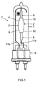
- FIG. 1 It consists of a tubular discharge vessel 2 made of ceramic, in which two electrodes are inserted (not visible).
- the discharge vessel has a central part 5 and two ends 4. At the ends sit two seals 6, which are designed here as capillaries.
- the discharge vessel is preferred and the seals are made integrally from a material such as PCA.
- the discharge vessel 2 is surrounded by an outer bulb 7, which terminates a base 8.
- the discharge vessel 2 is in the outer bulb by means of a frame which includes a short and long power supply 11 a and 11 b, supported.
- a ring cooling structure 10 which rotates about the seal.
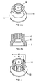
- FIG. 2a shows a ring cooling structure 10 in perspective view in conjunction with a short seal 16th
- FIG. 2b shows a longitudinal section of the region of a seal 16.
- the annulus cooling structure 10 sets in the tapered end portion 4 of the discharge vessel 2 and surrounds the seal at some distance.
- FIG. 3 shows a ring cooling structure 13, which instead of a constant inner diameter and outer diameter sickle-shaped or semicircular cut structures 19 has that attach externally to the ring 13.
- the inner diameter ID is constant
- the outer diameter AD varies periodically.
- small recesses 20 interrupt the ring structure 13, see FIG. 4 , This aims to increase the radiating surface.
- the number of recesses is advantageously up to three, as shown here.
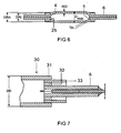
- FIG. 5 shows a discharge vessel 2, in which the seal is realized by a capillary.
- the cooling ring 13 has a recess 20.
- recess here is meant an interruption whose angle length is very small in the Compared to the angular length of the remaining ring.
- the recesses typically together make up at most 10% of the total angular length of 360 °. This value should be chosen as low as possible because the interruptions reduce the cooling capacity.
- Such concentric or partially concentric (partially) cylindrical projections of the cooling ring in the region of the tapered inner contour form a cooling structure, without this causing a heat flow longitudinally in the direction of the burner axis to the burner end region.
- the cooling effect on the surface zone of the burner vessel can be set locally and tailored to the particular requirements.
- the starting point of the cooling ring on the tapered end portion 4 is given by the inner diameter DRI, wherein DRI is in the range between 95% and 25% of the maximum diameter Dmax of the discharge vessel. Preferably, DRI is between 80% and 25% of Dmax.
- the wall thickness TH of the tapered end portion 4 is often not constant as shown here.
- the orientation of the annularly arranged cooling structure is selected ( FIG. 6 ) that the point of attachment of the ring structure is outside the narrowest point E of the tapered end portion 4.
- the entrance of the capillary is formed as a flat surface 25 which is transverse to the lamp axis, whereby a narrowest point inevitably results.
- DRA is the outer diameter of the ring structure.
- the minimum wall thickness in the end region preferably has 20-80% of the maximum wall thickness in the end region, as occurs in particular at the beginning of the taper.
- WD is the wall thickness in the center of the discharge vessel. If possible, the ring structure 13 should avoid that a wall thickness TH> WD occurs in the tapered end region 4, since otherwise an increased heat flow into the capillary cross-sectional area occurs and this can lead to increased heat conduction losses.
- FIG. 7 shows an embodiment of a discharge vessel 30, wherein the end 31 of the discharge vessel is not tapered, but the discharge vessel has a constant diameter DD.
- the capillary 6 is seated in a plug 32.
- the ring structure is inserted as a further plug-like cylindrical portion 33 between the plug 32 and the end 31 of the discharge vessel and each sintered with plug 32 and discharge vessel 30.
- FIG. 11 shows an embodiment in which a ring structure 39 has an axis-parallel base body 40 which surrounds a plug, and which has a radiating body inclined outwards in the form of a protruding circumferential fin or even individual spines 41. It can also be arranged several spines axially one behind the other on a base body.
- the deflection of the radiation body against the longitudinal axis is about 90 ° in order to avoid back reflection on the capillary 6 as far as possible. It is advantageous that the projecting length AB clearly extends the diameter DU of the discharge vessel 38 in order to minimize any return reflection.
- FIG. 12 shows an embodiment in which the base body 40, a plate-like end portion is attached as a radiating 43, which forms approximately at an angle of 45 ° to the longitudinal axis.
- FIG. 13 shows an embodiment in which the problem of back reflection has been solved in another way.
- the ring structure is tapering at the end remote from the discharge, so that its inner wall side, which faces the capillary, is chamfered (44) so that the emitted radiation reaches the outside obliquely after reflection at the capillary.
- an IR-reflecting coating 50 is preferably also applied to at least one of the two capillary surfaces and / or the inner side of the ring structure.
Landscapes
- Vessels And Coating Films For Discharge Lamps (AREA)
- Discharge Lamps And Accessories Thereof (AREA)
Description
- Die Erfindung geht aus von einer Hochdruckentladungslampe gemäß dem Oberbegriff des Anspruchs 1. Derartige Lampen sind insbesondere Hochdruckentladungslampen mit keramischen Entladungsgefäß für die Allgemeinbeleuchtung.
- Die
US-A 4 970 431 offenbart eine Natrium-Hochdruckentladungslampe, bei der der Kolben des Entladungsgefäßes aus Keramik gefertigt ist. An den zylindrischen Enden des Entladungsgefäßes sind flossenartige Fortsätze aufgesteckt, die der Wärmeabfuhr dienen. - Aus der
EP-A 506 182 - Eine Metallhalogenidlampen gemäß overbegriffs des Anspruchs 1 ist ans der
US-A-2005/184632 bekannt. - Die Aufgabe der vorliegenden Erfindung ist es, eine Hochdruckentladungslampe bereitzustellen, deren Farbstreuung gegenüber bisherigen Lampen deutlich reduziert ist.
- Diese Aufgabe wird gelöst durch die kennzeichnenden Merkmale des Anspruchs 1.
- Besonders vorteilhafte Ausgestaltungen finden sich in den abhängigen Ansprüchen.
- Die Hochdruckentladungslampe ist mit einem keramischen längsgestreckten Entladungsgefäß ausgestattet. Das Entladungsgefäß definiert eine Lampenachse und besitzt einen zentralen Teil und zwei Endbereiche, die jeweils durch Abdichtungen verschlossen sind, wobei Elektroden in den Abdichtungen verankert sind, die sich in das vom Entladungsgefäß umhüllte Entladungsvolumen erstrecken, wobei außerdem eine Füllung, die Metallhalogenide enthält, im Entladungsvolumen untergebracht ist. Dabei sitzt an mindestens einem Endbereich eine ringförmige Struktur, die sich, was zumindest ihren Grundkörper betrifft, im wesentlichen achsparallel nach außen erstreckt und von der Abdichtung beabstandet ist. Die Abdichtungen sind Kapillaren.
- Die Erfindung betrifft insbesondere Lampen mit erhöhtem Aspektverhältnis, oder auch Lampen, welche verkürzte Strukturen für die Abdichtungen aufweisen. Bevorzugt weist der Endenbereich eine sich verjüngende Innenkontur im Elektrodenrückraum auf. Das heißt, dass der zentrale Teil des Entladungsgefäßes einen maximalen oder konstanten Innendurchmesser ID besitzt und die Endbereiche einen kleineren Innendurchmesser aufweisen.
- Die Ringstruktur ist bevorzugt konzentrisch außen um die Elektrodenkonstruktion bzw. die Abdichtung am Endenbereich angeformt. Das Entladungsgefäß besteht typisch aus aluminiumhaltiger Keramik wie PCA oder auch YAG, AlN, oder AlY03. Es wird eine freistehende, von der Abdichtung beabstandete Kühlungsstruktur verwendet, die selbst aus Keramik geformt ist und insbesondere integraler Bestandteil des Endenbereichs sein kann. Es kann sich jedoch auch um ein separates Bauteil handeln, gemäß voliegender Erfindung aus transluzenter Keramik wie Al2O3 oder AlN, alternativ beispielsweise auch aus Steatit. Das separate Bauteil ist mittels Zement oder Kleber am Ende des Entladungsgefäßes befestigt.
- Die Erfindung ist besonders geeignet für hochbelastete Metallhalogenidlampen, bei denen das Verhältnis zwischen der Innenlänge IL und dem maximalen Innendurchmesser ID des Entladungsgefäßes, das sog. Aspektverhältnis IL/ID, zwischen 1,5 und 8 liegt.
- Es zeigt sich, dass bei diesen Brennerformen, insbesondere wenn sie zum Ende hin sich verjüngende Endenbereiche besitzen, eine lokale Endenkühlung sinnvoll ist. Diese verbessert die Füllungsverteilung im Brenner, weil sich die Füllung bevorzugt im Bereich hinter den Elektroden im sogenannten Elektroden-Rückraum ablagert und damit zu einer verbesserten Farbstabilität als auch zu einer erhöhten Lichtausbeute führt. Insbesondere bei Verwendung von Na- und/oder Ce-haltigen Füllungen lassen sich extrem hohe Lichtausbeuten mit hoher Farbwiedergabe erzielen. Es zeigt sich, dass bei Anwendung eines geeigneten Betriebsverfahrens die Leistungskennlinie der Lampe günstig beeinflusst werden kann, so dass eine Lichtausbeute bis über 150 1m/W bei Beibehaltung eines Farbwiedergabeindex Ra > 80 langzeitstabil erzielt werden kann. Derartige Betriebsverfahren sind beispielsweise in
EP 1560 472 ,EP 1 422 980 ,EP 1 729 324 undEP 1768 469 angegeben. - Unabhängig von der Formgebung der Wand zwischen den Elektroden kann der Temperaturgradient bei hochbelasteten Brennern, die typisch eine Wandbelastung von mindestens 30 W/cm2 im Bereich der axialen Länge zwischen den Elektroden erreichen, durch die Wahl des Ansatzpunktes für die Kühlstruktur beeinflusst und eingestellt werden. Damit kann die Konstanz der Farbtemperatur und die Ausbeute der resultierenden Metallhalogenidlampe wesentlich verbessert werden.
- Durch das Vermeiden eines Kontaktes zwischen Kühlstruktur und Abdichtung (meist eine Elektroden-Durchführungs-Kapillare) wird eine effektive Kühlung am Ansatzpunkt der Kühlstruktur gewährleistet und gleichzeitig ein Wärmefluss auf die Abdichtung vermieden. Dies vermindert die Verluste an den Enden und erhöht den Temperaturgradienten im Bereich der Abdichtung.
- Dies gilt insbesondere bei Metallhalogenidlampen, welche mindestens eines der Halogenide des Ce, Pr oder Nd, insbesondere zusammen mit Halogeniden des Na und/oder Li enthalten. Hier treten sonst Farbtemperaturschwankungen aufgrund von Destillationseffekten auf.
- Bevorzugt ist auch die Anwendung bei Lampen mit hohem Aspektverhältnis von 2 bis 6 und bei Lampen mit Anregung von akustischen Resonanzen, die zur Aufhebung von longitudinaler Segregation in vertikaler Brennlage verwendet werden.
- Erfindunggemäß sing die Abdichtungen als Kapillaren ausgeführt. Sie können aber auch anders ausgeführt sein, siehe beispielsweise
DE-A 197 27 429 , wo ein Cermetstift verwendet wird. - Besonders gute Kühlwirkung lässt sich bei Lampen mit konstantem Innendurchmesser erzielen, wenn der Kühlring den gleichen maximalen Durchmesser wie der Endenbereich hat. Aber auch ein kleinerer Durchmesser kann ausreichen.
- Im allgemeinen hat der Kühlring einen Innendurchmesser von 1,1 bis 2 x DU (DU = Außendurchmesser der Kapillare). Insbesondere ist seine Wandstärke etwa 0,3 bis 3 mm. Insbesondere kann die den Innendurchmesser mit dem Außendurchmesser verbindende Stirnfläche abgeschrägt sein. Sie kann auch mit einer Beschichtung versehen sein. Die Beschichtung sollte hochemissiv sein. Geeignete Materialien sind insbesondere Graphit oder Carbon, also andere Kohlenstoff-Modifikationen wie z.B. DLC (diamond-like carbon).
- Generell kann das Kühlungsverhalten auch dadurch gesteuert werden, daß ein Teil des Ringes wie die Stirnfläche mit einer Beschichtung hoher Emissivität bedeckt ist.
- Als Material des Kolbens kann PCA oder jede andere übliche Keramik verwendet werden. Auch die Wahl der Füllung unterliegt keiner besonderen Einschränkung.
- Entladungsgefäße für Hochdrucklampen mit annähernd gleichmäßiger Wanddickenverteilung und schlank auslaufenden Endenformen zeigen bisher abhängig von der Füllungszusammensetzung eine teilweise hohe Farbstreuung durch die starke Verteilung der Metallhalogenid-Füllung im Inneren des Entladungsgefäßes. Typisch kondensiert die Füllung im Bereich hinter einer Linie, die durch Projektion der Elektrodenspitze auf die innere Brenner-Oberfläche bestimmt ist. Die Füllungspositionierung auf eine Zone der Oberfläche im Innern des Entladungsgefäßes, die einem engen Temperaturbereich entspricht, und in die Restvolumina der -eventuell vorhandenen- Kapillaren hinein ist bisher nicht hinreichend genau einstellbar.
- Bisherige Entladungsgefäße haben oft eine Form mit verstärkter Wanddicke an den Endflächen, z.B. bei zylindrischen Brennerformen, und erzeugen dadurch eine vergrößerte Endenoberfläche. Ein weiteres Problem ist die durch den wanddickenabhängigen spezifischen Emissionskoeffizienten der Keramik erhöhte Abstrahlung von IR-Strahlung beim Betrieb des Entladungsgefäßes im evakuierten oder gasgefüllten Außenkolben.
- Hierdurch wird durch einen Wärmesenkeneffekt am Ende des Entladungsgefäßes der größte Teil der Füllung lokalisiert, die den Dampfdruck der verwendeten Metallhalogenide im Entladungsgefäß derart bestimmt, dass bei Keramiklampensystemen ein befriedigender Wert der Streuung der Farbtemperatur von höchstens 75 K für größere Lampengruppen gleicher Betriebsleistung einstellbar ist.
- Bei kugeligen Entladungsgefäßen oder solchen mit Halbkugelendformen oder konisch zulaufenden Endenformen oder elliptisch ausgeformten Endenformen und zylindrischem Mittenteil mit einem relativ hohen Aspektverhältnis von IL/ID von etwa 1,5 bis 8 ergeben sich besonders gravierende Probleme. Aufgrund des sich verjüngenden Übergangs in den Bereich der Abdichtung, meist ein Kapillarbereich, ergeben sich teilweise unzureichende Kühlungseffekte am Ende des Entladungsgefäßes und damit eine unzureichende Festlegung der Temperatur, die für eine zielgenaue Füllungsablagerung in einem engen Temperaturbereich der Innenwandung nicht ausreicht.
- Bei einer Brennergeometrie, die keine Kühlstruktur aufweist, siehe
Figur 8 , wird ein sehr kleiner Temperaturgradient von Brennerkörper zur Verschluss-Struktur erzeugt, was eine bevorzugte Destillation der Füllung in der Durchführungsstruktur zu Folge hat. - Bei einer Brennergeometrie, bei der die Abdichtung als massiver Stopfen ausgeführt ist, siehe
Figur 9 , wird ein vergrößerter Kühleffekt der Außenoberfläche erzeugt. Gleichzeitig wird aber auch eine große Wärmemenge in die angrenzende Abdichtung eingeführt, was eine vergrößerte Brennermasse und vergrößerte Wärmeleitungsverluste mit sich bringt. - Beide Lösungen haben Nachteile für die Leistungscharakteristik der Metallhalogenidlampe.
- Eine weitere bekannte Lösung (
Figur 10 ) sind Finnen oder flossenartige Ausformungen. Diese erhöhen zwar die kühlende Oberfläche, sie bilden jedoch eine Wärmebrücke zwischen Brennerende und Abdichtung, insbesondere wenn kurze Kühlungslängen bevorzugt werden und die Kühlungsstruktur eine erhöhte Anzahl von Kühlrippen aufweist. - Diese Nachteile werden von der erfindungsgemäßen Kühlstruktur in Ringform vermieden. In einer bevorzugten Ausführungsform der Erfindung ist die Kühlstruktur ganz oder teilweise mit einer Beschichtung versehen. Sie besteht aus einem Material, das im Nahen Infrarot (NIR), insbesondere im Wellenlängenbereich zwischen 1 und 3 µm, gegenüber dem keramischen Material der Kühlstruktur eine erhöhte hemisphärische Emissivität ε im Temperaturbereich zwischen 650 und 1000°C aufweist. Die Beschichtung sollte vorzugsweise im Bereich des Überganges zwischen dem Ende des Entladungsgefäßes und der Abdichtung angebracht sein. Als Beschichtungsmaterialien eignen sich hochtemperaturfeste Beschichtungen mit hemisphärischen Emissionskoeffizienten ε, wobei für ε bevorzugt gilt, dass ε ≥ 0,6. Darunter fällt Graphit, Mischungen von A1203 mit Graphit, Mischungen von Al203 mit Carbiden der Metalle Ti, Ta, Hf, Zr, sowie von Halbmetallen wie Si. Geeignet sich auch Mischungen, die noch zusätzlich andere Metalle zur Einstellung eventuell gewünschter elektrischer Leitfähigkeit enthalten.
- Selbstverständlich können beide Maßnahmen miteinander geeignet kombiniert werden, so dass ein Teil der Oberflächenabstrahlungserhöhung über eine Vergrößerung der Oberfläche durch die Ringstruktur und gleichzeitig ein Teil durch die Beschichtung von Teilen dieser Ringstruktur oder der angrenzenden kälteren Abdichtungsbereiche erfolgt.
- Insgesamt ergeben sich eine Reihe von Vorteilen bei Verwendung eines integralen Kühlrings bei keramischen Entladungsgefäßen:
- 1. Effektivere Kühlung bei gleichzeitig relativ geringer zusätzlicher Keramikmasse;
- 2. Verringerung des longitudinalen Wärmeflusses in die Abdichtung;
- 3. deutlich vergrößerte Flexibilität der Oberflächeneinstellung im Endenbereich;
- 4. Verringerung der Abschattungseffekte im Raumwinkelbereich der Elektrodenzuführung;
- 5. Einstellbarkeit effektiver lokaler Thermostatwirkung mittels relativ kleiner Oberflächenbereiche.
- Diese Eigenschaften sind insbesondere für hochbelastete Formen von Entladungsgefäßen mit kleiner Gesamtoberfläche und evtl. erhöhtem Aspektverhältnis wichtig, da unter diesen Voraussetzungen eine lokale Kühlung durch Wärmefluss über relativ große Wandquerschnittsflächen schwierig wird.
- Die Gesamtmasse des Entladungsgefäßes erhöht sich durch diese Art von Ringkühlung nur unwesentlich und bleibt damit unter einem kritischen Wert, der das Anlaufverhalten der Lampe bei der Zündung negativ beeinflussen würde. Es gibt somit einen ausgeklügelten Kompromiss zwischen guter Zündung und effektiver Kühlung. Diese Maßnahme erlaubt eine sehr hohe Farbstabilität unter der bewussten Inkaufnahme einer schlechten Isothermie. Dies geschieht in Abkehr von der bisherigen Zielsetzung möglichst guter Isothermie und erlaubt es, die Zone der Kondensation der Füllung exakt zu bestimmen durch bewusste Gestaltung eines Temperaturgradienten.
- Die Kühlwirkung lässt sich insbesondere steuern durch die maximale Höhe der Ringkühlung, insbesondere wenn sie am Endenbereich des Entladungsgefäß ansetzt, da je nach Ansatzhöhe die Ableitung von einem anderen Temperaturniveau aus erfolgt.
- Ein besonderer Vorteil einer derartigen integralen Ringkühlung ist, dass sie nicht nur effektiv kühlt, sondern daß sie auch einfach herzustellen ist, wenn man moderne Fertigungsverfahren wie Spritzguss, Schlickerguss oder rapid prototyping verwendet.
- Im Folgenden soll die Erfindung anhand mehrerer Ausführungsbeispiele näher erläutert werden. Die Figuren zeigen:
- Fig. 1
- eine Hochdruckentladungslampe mit Entladungsgefäß;
- Fig. 2
- ein Detail des Entladungsgefäßes aus
Figur 1 in Perspektive (Fig. 2a ) und in Längsschnitt (Fig 2b ); - Fig. 3-4
- ein weiteres Ausführungsbeispiel eines Endenbereichs eines Entladungsgefäßes;
- Fig. 5-6
- ein weiteres Ausführungsbeispiel eines Entladungsgefäßes;
- Fig. 7
- ein weiteres Ausführungsbeispiel eines Endenbereichs eines Entladungsgefäßes;
- Figur 8-10
- Ausführungsbeispiele eines Endenbereichs gemäß dem Stand der Technik;
- Figur 11-13
- weitere Ausführungsbeispiele eines EndenBereichs eines Entladungsgefäßes.
-
Figur 1 zeigt eine Metallhalogenidlampe 1. Sie besteht aus einem rohrartigen Entladungsgefäß 2 aus Keramik, in das zwei Elektroden eingeführt sind (nicht sichtbar). Das Entladungsgefäß hat einen zentralen Teil 5 und zwei Enden 4. An den Enden sitzen zwei Abdichtungen 6, die hier als Kapillaren ausgeführt sind. Bevorzugt ist das Entladungsgefäß und die Abdichtungen integral aus einem Material wie PCA hergestellt. - Das Entladungsgefäß 2 ist von einem Außenkolben 7 umgeben, den ein Sockel 8 abschließt. Das Entladungsgefäß 2 ist im Außenkolben mittels eines Gestells, das eine kurze und lange Stromzuführung 11 a und 11b beinhaltet, gehaltert. An den Abdichtungen 6 sitzt jeweils eine Ringkühlungsstruktur 10, die um die Abdichtung umläuft.
-
Figur 2a zeigt eine Ringkühlungsstruktur 10 in perspektivischer Ansicht in Verbindung mit einer kurzen Abdichtung 16.Figur 2b zeigt einen Längsschnitt des Bereichs einer Abdichtung 16. Die Ringkühlungsstruktur 10 setzt im sich verjüngenden Endenbereich 4 des Entladungsgefäßes 2 an und umgibt die Abdichtung mit einigem Abstand. -
Figur 3 zeigt eine Ringkühlungsstruktur 13, die statt eines konstanten Innendurchmessers und Außendurchmessers sichelförmig oder auch halbkreisförmig ausgeschnittene Strukturen 19 besitzt, die außen am Ring 13 ansetzen. Somit ist der Innendurchmesser ID zwar konstant, aber der Außendurchmesser AD variiert periodisch. - Schließlich ist es auch möglich, dass kleine Aussparungen 20 die Ringstruktur 13 unterbrechen, siehe
Figur 4 . Dies zielt darauf ab, die abstrahlende Oberfläche zu vergrößern. Die Anzahl der Aussparungen beträgt vorteilhaft bis drei, wie hier gezeigt. -
Figur 5 zeigt ein Entladungsgefäß 2, bei dem die Abdichtung durch eine Kapillare realisiert ist. Der Kühlring 13 weist eine Aussparung 20 auf. Mit Aussparung ist hier eine Unterbrechung gemeint, deren Winkellänge sehr klein im Vergleich zur Winkellänge des verbleibenden Ringes ist. Die Aussparungen machen zusammen typisch höchstens 10 % der gesamten Winkellänge von 360° aus. Dieser Wert ist deshalb möglichst niedrig zu wählen, weil die Unterbrechungen die Kühlleistung mindern. Derartige konzentrische oder teilweise konzentrisch angeordnete (teil)zylindrische Ansätze des Kühlrings im Bereich der sich verjüngenden Innenkontur bilden eine Kühlstruktur, ohne dass dies longitudinal in Richtung der Brennerachse einen Wärmefluss zum Brennerendenbereich bewirkt. - Durch Ansatzort, Wandstärke und Höhe des Kühlrings lässt sich der Kühleffekt auf der Oberflächenzone des Brennergefäßes lokal einstellen und auf die jeweiligen Erfordernisse maßschneidern.
- Der Ansatzpunkt des Kühlrings auf dem sich verjüngenden Endenbereich 4 ist gegeben ist durch den Innendurchmesser DRI, wobei DRI im Bereich zwischen 95% und 25% des Maximaldurchmessers Dmax des Entladungsgefäßes liegt. Bevorzugt liegt DRI zwischen 80% und 25% von Dmax. Die Wandstärke TH des sich verjüngenden Endenbereichs 4 ist häufig, wie hier gezeigt, nicht konstant. Bevorzugt wird die Orientierung der ringförmig angeordneten Kühlstruktur derart gewählt (
Figur 6 ), dass der Ansatzpunkt der Ringstruktur außerhalb der engsten Stelle E des sich verjüngenden Endenbereich 4 liegt. Häufig ist der Eingang der Kapillare als ebene Fläche 25 ausgebildet, die quer zur Lampenachse liegt, wodurch eine engste Stelle sich zwangsläufig ergibt. DRA ist der Außendurchmesser der Ringstruktur. - Die minimale Wandstärke im Endenbereich besitzt bevorzugt 20-80% der maximalen Wandstärke im Endenbereich, wie sie insbesondere am Beginn der Verjüngung auftritt.
- WD ist die Wandstärke im Zentrum des Entladungsgefäßes. Die Ringstruktur 13 sollte möglichst vermeiden, dass im sich verjüngenden Endenbereich 4 eine Wandstärke TH > WD auftritt, da sonst ein erhöhter Wärmefluss in die Kapillarquerschnittsfläche erfolgt und dies zu erhöhten Wärmeleitungsverlusten führen kann.
-
Figur 7 zeigt ein Ausführungsbeispiel eines Entladungsgefäßes 30, bei dem das Ende 31 des Entladungsgefäßes sich nicht verjüngt, sondern das Entladungsgefäß einen konstanten Durchmesser DD aufweist. Die Kapillare 6 sitzt in einem Stopfen 32. Die Ringstruktur ist als weiteres stopfenartiges zylindrisches Teil 33 zwischen Stopfen 32 und Ende 31 des Entladungsgefäßes eingesetzt und jeweils mit Stopfen 32 und Entladungsgefäß 30 versintert. - Integrale Kühlstrukturen sollten in etwa achsparallel sein, damit sie leicht zu fertigen sind. Vorteilhaft sind jedoch in ihrer Geometrie modifizierte Kühlstrukturen, die von der Achsparallelität abweichen. Damit wird eine Rück-Reflexion auf das Ende des Entladungsgefäßes, insbesondere auf die Kapillare elegant und effektiv vermieden.
Figur 11 zeigt ein Ausführungsbeispiel, bei dem eine Ringstruktur 39 einen achsparallelen Grundkörper 40 hat, der einen Stopfen umgibt, und der einen von der Achse nach außen geneigten Abstrahlungskörper in Gestalt einer abstehenden umlaufenden Finne oder auch einzelner Stacheln 41 hat. Es können auch mehrere Stacheln axial hintereinander auf einem Grundkörper angeordnet sein. - Bevorzugt ist die Ablenkung des Abstrahlungskörpers gegen die Längsachse etwa 90°, um Rückreflexion auf die Kapillare 6 weitestgehend zu vermeiden. Vorteilhaft ist, dass die abstehende Länge AB deutlich den Durchmesser DU des Entladungsgefäßes 38 verlängert um jegliche Rückreflexion zu minimieren.
-
Figur 12 zeigt ein Ausführungsbeispiel, bei dem am Grundkörper 40 ein tellerartiges Endteil als Abstrahlkörper 43 angesetzt ist, das etwa einen Winkel von 45° zur Längsachse bildet. -
Figur 13 zeigt ein Ausführungsbeispiel, bei dem das Problem der Rückreflexion auf andere Weise gelöst worden ist. Hier ist die Ringstruktur am entladungsfernen Ende spitz zulaufend, so dass ihre innenliegende Wandseite, die zur Kapillare zeigt, so abgeschrägt (44) ist, dass die abgegebene Strahlung nach Reflexion an der Kapillare schräg nach außen gelangt. Zur verbesserten Unterdrückung der schädlichen IR-Strahlung sind außerdem bevorzugt auf mindestens einer der beiden Flächen Kapillare und/oder Innenseite der Ringstruktur eine IR-reflektierende Beschichtung 50 wie an sich bekannt aufgebracht.
Claims (10)
- Hochdruckentladungslampe (1) mit einem keramischen längsgestreckten Entladungsgefäß (2) mit einem zentralen Teil (5) und zwei Enden (4) und einer Achse, wobei die Enden (4) durch Abdichtungen (6), die als Kapillaren ausgebildet sind, verschlossen sind, wobei Elektroden in den Abdichtungen (6) verankert sind, die sich in das vom Entladungsgefäß (2) umhüllte Entladungsvolumen erstrecken, wobei eine Füllung, die Metallhalogenide enthält, im Entladungsvolumen untergebracht ist, dadurch gekennzeichnet, dass an mindestens einem ersten Ende (4) eine Ringstruktur (10;13) sitzt, die aus Keramik geformt ist, und die beabstandet von der Abdichtung (6) ist und die um die Abdichtung (6) herumläuft.
- Hochdruckentladungslampe nach Anspruch. 1, dadurch gekennzeichnet, dass zumindest ein Grundkörper (40) der Ringstruktur sich achsparallel nach außen erstreckt.
- Hochdruckentladungslampe nach Anspruch 1, dadurch gekennzeichnet, dass das erste Ende (4) sich verjüngt und die Ringstruktur im sich verjüngenden Endenbereich ansetzt.
- Hochdruckentladungslampe nach Anspruch 1, dadurch gekennzeichnet, dass das Entladungsgefäß (2) ein Aspektverhältnis von 1,5 bis 8 besitzt.
- Hochdruckentladungslampe nach Anspruch 1, dadurch gekennzeichnet, dass die Ringstruktur (10;13) außerhalb der engsten Stelle des Endenbereichs ansetzt.
- Hochdruckentladungslampe nach Anspruch 1, dadurch gekennzeichnet, dass der Außendurchmesser der Ringstruktur konstant ist oder periodisch variiert.
- Hochdruckentladungslampe nach Anspruch 1, dadurch gekennzeichnet, dass die Ringstruktur maximal drei Unterbrechungen besitzt.
- Hochdruckentladungslampe nach Anspruch 1, dadurch gekennzeichnet, dass die Wandstärke der Ringstruktur im Bereich von 0,5 bis 3 mm liegt.
- Hochdruckentladungslampe nach Anspruch 1, dadurch gekennzeichnet, dass die Stirnseite der Ringstruktur abgeschrägt ist und insbesondere mit einer Beschichtung versehen ist.
- Hochdruckentladungslampe nach Anspruch 2, dadurch gekennzeichnet, dass die Ringstruktur einen achsparallelen Grundkörper (40) sowie einen von der Längsachse nach außen geneigten Abstrahlkörper (43) besitzt.
Applications Claiming Priority (2)
| Application Number | Priority Date | Filing Date | Title |
|---|---|---|---|
| DE102007045079A DE102007045079A1 (de) | 2007-09-21 | 2007-09-21 | Hochdruckentladungslampe |
| PCT/EP2008/060860 WO2009040193A2 (de) | 2007-09-21 | 2008-08-19 | Hochdruckentladungslampe |
Publications (2)
| Publication Number | Publication Date |
|---|---|
| EP2201596A2 EP2201596A2 (de) | 2010-06-30 |
| EP2201596B1 true EP2201596B1 (de) | 2012-12-05 |
Family
ID=40380269
Family Applications (1)
| Application Number | Title | Priority Date | Filing Date |
|---|---|---|---|
| EP08803097A Not-in-force EP2201596B1 (de) | 2007-09-21 | 2008-08-19 | Hochdruckentladungslampe |
Country Status (7)
| Country | Link |
|---|---|
| US (1) | US20100308706A1 (de) |
| EP (1) | EP2201596B1 (de) |
| JP (1) | JP2010539665A (de) |
| CN (1) | CN101802974A (de) |
| DE (1) | DE102007045079A1 (de) |
| TW (1) | TW200921749A (de) |
| WO (1) | WO2009040193A2 (de) |
Families Citing this family (2)
| Publication number | Priority date | Publication date | Assignee | Title |
|---|---|---|---|---|
| DE102009029867A1 (de) * | 2009-06-22 | 2010-12-23 | Osram Gesellschaft mit beschränkter Haftung | Hochdruckentladungslampe |
| DE102012213191A1 (de) * | 2012-07-26 | 2014-01-30 | Osram Gmbh | 2hochdruckentladungslampe |
Family Cites Families (24)
| Publication number | Priority date | Publication date | Assignee | Title |
|---|---|---|---|---|
| JPS5753059A (en) * | 1980-09-17 | 1982-03-29 | Matsushita Electronics Corp | High pressure sodium vapor lamp |
| GB8519582D0 (en) * | 1985-08-03 | 1985-09-11 | Emi Plc Thorn | Discharge lamps |
| US4823050A (en) * | 1986-09-18 | 1989-04-18 | Gte Products Corporation | Metal-halide arc tube and lamp having improved uniformity of azimuthal luminous intensity |
| US4970431A (en) | 1987-11-03 | 1990-11-13 | U.S. Philips Corporation | High-pressure sodium discharge lamp with fins radially extending from the discharge vessel for controlling the wall temperature of the discharge vessel |
| US4983889A (en) * | 1989-05-15 | 1991-01-08 | General Electric Company | Discharge lamp using acoustic resonant oscillations to ensure high efficiency |
| DE69213523T2 (de) | 1991-03-28 | 1997-03-13 | Philips Electronics Nv | Hochdruck-Gasentladungslampen |
| DE4242123A1 (de) * | 1992-12-14 | 1994-06-16 | Patent Treuhand Ges Fuer Elektrische Gluehlampen Mbh | Hochdruckentladungslampe mit einem keramischen Entladungsgefäß |
| JP3189661B2 (ja) * | 1996-02-05 | 2001-07-16 | ウシオ電機株式会社 | 光源装置 |
| JPH11238488A (ja) * | 1997-06-06 | 1999-08-31 | Toshiba Lighting & Technology Corp | メタルハライド放電ランプ、メタルハライド放電ランプ点灯装置および照明装置 |
| DE19727429A1 (de) | 1997-06-27 | 1999-01-07 | Patent Treuhand Ges Fuer Elektrische Gluehlampen Mbh | Metallhalogenidlampe mit keramischem Entladungsgefäß |
| JPH11283573A (ja) * | 1998-03-30 | 1999-10-15 | Toshiba Lighting & Technology Corp | 高圧放電ランプ及び照明装置 |
| EP1182681B1 (de) * | 2000-08-23 | 2006-03-01 | General Electric Company | Spritzgegossene Keramik-Metallhalogenidbogenröhre mit einem nicht-konischen Ende |
| WO2002091429A1 (en) * | 2001-05-10 | 2002-11-14 | Koninklijke Philips Electronics N.V. | High-pressure gas discharge lamp |
| AU2002356378A1 (en) * | 2002-01-16 | 2003-07-30 | Koninklijke Philips Electronics N.V. | Gas discharge lamp |
| CA2422433A1 (en) * | 2002-05-16 | 2003-11-16 | Walter P. Lapatovich | Electric lamp with condensate reservoir and method of operation thereof |
| DE10253904A1 (de) * | 2002-11-19 | 2004-06-03 | Patent-Treuhand-Gesellschaft für elektrische Glühlampen mbH | Betriebsverfahren und System für den Resonanzbetrieb von Hochdrucklampen im longitudinalen Mode |
| JP3855955B2 (ja) * | 2003-03-28 | 2006-12-13 | セイコーエプソン株式会社 | 光源装置及びプロジェクタ |
| JP4273912B2 (ja) * | 2003-10-07 | 2009-06-03 | ウシオ電機株式会社 | 光源装置 |
| DE102004004828A1 (de) | 2004-01-30 | 2005-08-18 | Patent-Treuhand-Gesellschaft für elektrische Glühlampen mbH | Betriebsverfahren für den Resonanzbetrieb von Hochdrucklampen im longitudinalen Mode und zugehöriges System und EVG |
| US7030543B2 (en) * | 2004-02-24 | 2006-04-18 | Osram Sylvania Inc. | Reflector lamp having reduced seal temperature |
| DE102005025155A1 (de) * | 2005-06-01 | 2006-12-07 | Patent-Treuhand-Gesellschaft für elektrische Glühlampen mbH | Hochdrucklampe und zugehöriges Betriebsverfahren für den Resonanzbetrieb von Hochdrucklampen im longitudinalen Mode und zugehöriges System |
| ATE540560T1 (de) | 2005-09-23 | 2012-01-15 | Osram Ag | Verfahren zum betreiben einer hochdruckentladungslampe |
| DE102006002261A1 (de) * | 2006-01-17 | 2007-07-19 | Patent-Treuhand-Gesellschaft für elektrische Glühlampen mbH | Hochdruckentladungslampe |
| US7728495B2 (en) * | 2007-08-01 | 2010-06-01 | Osram Sylvania Inc. | HID lamp with frit seal thermal control |
-
2007
- 2007-09-21 DE DE102007045079A patent/DE102007045079A1/de not_active Withdrawn
-
2008
- 2008-08-19 JP JP2010525291A patent/JP2010539665A/ja active Pending
- 2008-08-19 US US12/679,040 patent/US20100308706A1/en not_active Abandoned
- 2008-08-19 CN CN200880108150A patent/CN101802974A/zh active Pending
- 2008-08-19 EP EP08803097A patent/EP2201596B1/de not_active Not-in-force
- 2008-08-19 WO PCT/EP2008/060860 patent/WO2009040193A2/de not_active Ceased
- 2008-09-19 TW TW097135926A patent/TW200921749A/zh unknown
Also Published As
| Publication number | Publication date |
|---|---|
| US20100308706A1 (en) | 2010-12-09 |
| DE102007045079A1 (de) | 2009-04-02 |
| TW200921749A (en) | 2009-05-16 |
| CN101802974A (zh) | 2010-08-11 |
| EP2201596A2 (de) | 2010-06-30 |
| JP2010539665A (ja) | 2010-12-16 |
| WO2009040193A3 (de) | 2009-06-04 |
| WO2009040193A2 (de) | 2009-04-02 |
Similar Documents
| Publication | Publication Date | Title |
|---|---|---|
| EP0839381B1 (de) | Reflektorlampe | |
| DE69600960T2 (de) | Hochdruckentladungslampe | |
| DE69805390T2 (de) | Metalldampfentladungslampe | |
| DE69111799T2 (de) | Kolbengeometrie für metallhalogenidentladungslampe mit geringer leistung. | |
| DE19645960A1 (de) | Keramisches Entladungsgefäß | |
| DE2623099A1 (de) | Kurzbogenentladungslampe | |
| EP0703600B1 (de) | Hochdruckentladungslampe | |
| EP1974367B1 (de) | Hochdruckentladungslampe mit am ende des entladungsgefässes angebrachten kühllamellen | |
| EP0602529B1 (de) | Hochdruckentladungslampe mit einem keramischen Entladungsgefäss | |
| DE1764299B2 (de) | Leitungseinfuehrung fuer eine elektrische entladungslampe | |
| EP0086479B1 (de) | Hochdruckentladungslampe | |
| EP0451647A2 (de) | Hochdruckentladungslampe und Verfahren zu ihrer Herstellung | |
| DE1910538A1 (de) | Elektrische Bogenlampe | |
| EP2020018A1 (de) | Hochdruckentladungslampe | |
| EP2201596B1 (de) | Hochdruckentladungslampe | |
| EP0825636B1 (de) | Hochdruckentladungslampe | |
| EP1730766B1 (de) | Elektrodensystem für eine hochdruckentladungslampe | |
| DE69825035T2 (de) | Hochdruck-Entladungslampe | |
| EP3948934B1 (de) | Elektrode für eine gasentladungslampe und gasentladungslampe | |
| EP2394291A1 (de) | Hochdruckentladungslampe | |
| DE20106002U1 (de) | Metallhalogenidlampe mit keramischem Entladungsgefäß | |
| EP2281298B1 (de) | Hochdruckentladungslampe | |
| DE102012209078B4 (de) | Blitzlampe mit prismatischem Lampenkörper | |
| DE202010018034U1 (de) | Hochdruckentladungslampe | |
| DE2410398B2 (de) | Hochdrucknatriumdampfentladungslampe mit einer in einem aussenkolben angeordneten entladungsroehre aus aluminiumoxyd |
Legal Events
| Date | Code | Title | Description |
|---|---|---|---|
| PUAI | Public reference made under article 153(3) epc to a published international application that has entered the european phase |
Free format text: ORIGINAL CODE: 0009012 |
|
| 17P | Request for examination filed |
Effective date: 20100211 |
|
| AK | Designated contracting states |
Kind code of ref document: A2 Designated state(s): AT BE BG CH CY CZ DE DK EE ES FI FR GB GR HR HU IE IS IT LI LT LU LV MC MT NL NO PL PT RO SE SI SK TR |
|
| AX | Request for extension of the european patent |
Extension state: AL BA MK RS |
|
| RIN1 | Information on inventor provided before grant (corrected) |
Inventor name: STOCKWALD, KLAUS Inventor name: SCHALK, BERNHARD |
|
| GRAP | Despatch of communication of intention to grant a patent |
Free format text: ORIGINAL CODE: EPIDOSNIGR1 |
|
| DAX | Request for extension of the european patent (deleted) | ||
| RAP1 | Party data changed (applicant data changed or rights of an application transferred) |
Owner name: OSRAM AG |
|
| GRAS | Grant fee paid |
Free format text: ORIGINAL CODE: EPIDOSNIGR3 |
|
| GRAA | (expected) grant |
Free format text: ORIGINAL CODE: 0009210 |
|
| AK | Designated contracting states |
Kind code of ref document: B1 Designated state(s): AT BE BG CH CY CZ DE DK EE ES FI FR GB GR HR HU IE IS IT LI LT LU LV MC MT NL NO PL PT RO SE SI SK TR |
|
| REG | Reference to a national code |
Ref country code: GB Ref legal event code: FG4D Free format text: NOT ENGLISH |
|
| REG | Reference to a national code |
Ref country code: CH Ref legal event code: EP |
|
| REG | Reference to a national code |
Ref country code: AT Ref legal event code: REF Ref document number: 587667 Country of ref document: AT Kind code of ref document: T Effective date: 20121215 |
|
| RAP2 | Party data changed (patent owner data changed or rights of a patent transferred) |
Owner name: OSRAM GMBH |
|
| REG | Reference to a national code |
Ref country code: IE Ref legal event code: FG4D Free format text: LANGUAGE OF EP DOCUMENT: GERMAN |
|
| REG | Reference to a national code |
Ref country code: DE Ref legal event code: R096 Ref document number: 502008008838 Country of ref document: DE Effective date: 20130131 |
|
| REG | Reference to a national code |
Ref country code: AT Ref legal event code: HC Ref document number: 587667 Country of ref document: AT Kind code of ref document: T Owner name: OSRAM GMBH, DE Effective date: 20130204 |
|
| RAP2 | Party data changed (patent owner data changed or rights of a patent transferred) |
Owner name: OSRAM GMBH |
|
| PG25 | Lapsed in a contracting state [announced via postgrant information from national office to epo] |
Ref country code: LT Free format text: LAPSE BECAUSE OF FAILURE TO SUBMIT A TRANSLATION OF THE DESCRIPTION OR TO PAY THE FEE WITHIN THE PRESCRIBED TIME-LIMIT Effective date: 20121205 Ref country code: ES Free format text: LAPSE BECAUSE OF FAILURE TO SUBMIT A TRANSLATION OF THE DESCRIPTION OR TO PAY THE FEE WITHIN THE PRESCRIBED TIME-LIMIT Effective date: 20130316 Ref country code: NO Free format text: LAPSE BECAUSE OF FAILURE TO SUBMIT A TRANSLATION OF THE DESCRIPTION OR TO PAY THE FEE WITHIN THE PRESCRIBED TIME-LIMIT Effective date: 20130305 Ref country code: FI Free format text: LAPSE BECAUSE OF FAILURE TO SUBMIT A TRANSLATION OF THE DESCRIPTION OR TO PAY THE FEE WITHIN THE PRESCRIBED TIME-LIMIT Effective date: 20121205 Ref country code: SE Free format text: LAPSE BECAUSE OF FAILURE TO SUBMIT A TRANSLATION OF THE DESCRIPTION OR TO PAY THE FEE WITHIN THE PRESCRIBED TIME-LIMIT Effective date: 20121205 |
|
| REG | Reference to a national code |
Ref country code: NL Ref legal event code: VDEP Effective date: 20121205 |
|
| REG | Reference to a national code |
Ref country code: LT Ref legal event code: MG4D |
|
| PG25 | Lapsed in a contracting state [announced via postgrant information from national office to epo] |
Ref country code: SI Free format text: LAPSE BECAUSE OF FAILURE TO SUBMIT A TRANSLATION OF THE DESCRIPTION OR TO PAY THE FEE WITHIN THE PRESCRIBED TIME-LIMIT Effective date: 20121205 Ref country code: PL Free format text: LAPSE BECAUSE OF FAILURE TO SUBMIT A TRANSLATION OF THE DESCRIPTION OR TO PAY THE FEE WITHIN THE PRESCRIBED TIME-LIMIT Effective date: 20121205 Ref country code: LV Free format text: LAPSE BECAUSE OF FAILURE TO SUBMIT A TRANSLATION OF THE DESCRIPTION OR TO PAY THE FEE WITHIN THE PRESCRIBED TIME-LIMIT Effective date: 20121205 Ref country code: GR Free format text: LAPSE BECAUSE OF FAILURE TO SUBMIT A TRANSLATION OF THE DESCRIPTION OR TO PAY THE FEE WITHIN THE PRESCRIBED TIME-LIMIT Effective date: 20130306 |
|
| PG25 | Lapsed in a contracting state [announced via postgrant information from national office to epo] |
Ref country code: IS Free format text: LAPSE BECAUSE OF FAILURE TO SUBMIT A TRANSLATION OF THE DESCRIPTION OR TO PAY THE FEE WITHIN THE PRESCRIBED TIME-LIMIT Effective date: 20130405 Ref country code: CZ Free format text: LAPSE BECAUSE OF FAILURE TO SUBMIT A TRANSLATION OF THE DESCRIPTION OR TO PAY THE FEE WITHIN THE PRESCRIBED TIME-LIMIT Effective date: 20121205 Ref country code: SK Free format text: LAPSE BECAUSE OF FAILURE TO SUBMIT A TRANSLATION OF THE DESCRIPTION OR TO PAY THE FEE WITHIN THE PRESCRIBED TIME-LIMIT Effective date: 20121205 Ref country code: BG Free format text: LAPSE BECAUSE OF FAILURE TO SUBMIT A TRANSLATION OF THE DESCRIPTION OR TO PAY THE FEE WITHIN THE PRESCRIBED TIME-LIMIT Effective date: 20130305 Ref country code: EE Free format text: LAPSE BECAUSE OF FAILURE TO SUBMIT A TRANSLATION OF THE DESCRIPTION OR TO PAY THE FEE WITHIN THE PRESCRIBED TIME-LIMIT Effective date: 20121205 |
|
| PG25 | Lapsed in a contracting state [announced via postgrant information from national office to epo] |
Ref country code: RO Free format text: LAPSE BECAUSE OF FAILURE TO SUBMIT A TRANSLATION OF THE DESCRIPTION OR TO PAY THE FEE WITHIN THE PRESCRIBED TIME-LIMIT Effective date: 20121205 Ref country code: PT Free format text: LAPSE BECAUSE OF FAILURE TO SUBMIT A TRANSLATION OF THE DESCRIPTION OR TO PAY THE FEE WITHIN THE PRESCRIBED TIME-LIMIT Effective date: 20130405 Ref country code: NL Free format text: LAPSE BECAUSE OF FAILURE TO SUBMIT A TRANSLATION OF THE DESCRIPTION OR TO PAY THE FEE WITHIN THE PRESCRIBED TIME-LIMIT Effective date: 20121205 |
|
| PLBE | No opposition filed within time limit |
Free format text: ORIGINAL CODE: 0009261 |
|
| STAA | Information on the status of an ep patent application or granted ep patent |
Free format text: STATUS: NO OPPOSITION FILED WITHIN TIME LIMIT |
|
| REG | Reference to a national code |
Ref country code: DE Ref legal event code: R081 Ref document number: 502008008838 Country of ref document: DE Owner name: OSRAM GMBH, DE Free format text: FORMER OWNER: OSRAM AG, 81543 MUENCHEN, DE Effective date: 20121212 Ref country code: DE Ref legal event code: R081 Ref document number: 502008008838 Country of ref document: DE Owner name: OSRAM GMBH, DE Free format text: FORMER OWNER: OSRAM GMBH, 81543 MUENCHEN, DE Effective date: 20130823 Ref country code: DE Ref legal event code: R081 Ref document number: 502008008838 Country of ref document: DE Owner name: LEDVANCE GMBH, DE Free format text: FORMER OWNER: OSRAM GMBH, 81543 MUENCHEN, DE Effective date: 20130823 Ref country code: DE Ref legal event code: R081 Ref document number: 502008008838 Country of ref document: DE Owner name: LEDVANCE GMBH, DE Free format text: FORMER OWNER: OSRAM AG, 81543 MUENCHEN, DE Effective date: 20121212 |
|
| PG25 | Lapsed in a contracting state [announced via postgrant information from national office to epo] |
Ref country code: DK Free format text: LAPSE BECAUSE OF FAILURE TO SUBMIT A TRANSLATION OF THE DESCRIPTION OR TO PAY THE FEE WITHIN THE PRESCRIBED TIME-LIMIT Effective date: 20121205 |
|
| 26N | No opposition filed |
Effective date: 20130906 |
|
| PG25 | Lapsed in a contracting state [announced via postgrant information from national office to epo] |
Ref country code: HR Free format text: LAPSE BECAUSE OF FAILURE TO SUBMIT A TRANSLATION OF THE DESCRIPTION OR TO PAY THE FEE WITHIN THE PRESCRIBED TIME-LIMIT Effective date: 20121205 Ref country code: CY Free format text: LAPSE BECAUSE OF FAILURE TO SUBMIT A TRANSLATION OF THE DESCRIPTION OR TO PAY THE FEE WITHIN THE PRESCRIBED TIME-LIMIT Effective date: 20121205 |
|
| PG25 | Lapsed in a contracting state [announced via postgrant information from national office to epo] |
Ref country code: IT Free format text: LAPSE BECAUSE OF FAILURE TO SUBMIT A TRANSLATION OF THE DESCRIPTION OR TO PAY THE FEE WITHIN THE PRESCRIBED TIME-LIMIT Effective date: 20121205 |
|
| REG | Reference to a national code |
Ref country code: DE Ref legal event code: R097 Ref document number: 502008008838 Country of ref document: DE Effective date: 20130906 |
|
| BERE | Be: lapsed |
Owner name: OSRAM A.G. Effective date: 20130831 |
|
| REG | Reference to a national code |
Ref country code: CH Ref legal event code: PL |
|
| GBPC | Gb: european patent ceased through non-payment of renewal fee |
Effective date: 20130819 |
|
| PG25 | Lapsed in a contracting state [announced via postgrant information from national office to epo] |
Ref country code: LI Free format text: LAPSE BECAUSE OF NON-PAYMENT OF DUE FEES Effective date: 20130831 Ref country code: CH Free format text: LAPSE BECAUSE OF NON-PAYMENT OF DUE FEES Effective date: 20130831 Ref country code: MC Free format text: LAPSE BECAUSE OF FAILURE TO SUBMIT A TRANSLATION OF THE DESCRIPTION OR TO PAY THE FEE WITHIN THE PRESCRIBED TIME-LIMIT Effective date: 20121205 |
|
| REG | Reference to a national code |
Ref country code: IE Ref legal event code: MM4A |
|
| REG | Reference to a national code |
Ref country code: FR Ref legal event code: ST Effective date: 20140430 |
|
| PG25 | Lapsed in a contracting state [announced via postgrant information from national office to epo] |
Ref country code: BE Free format text: LAPSE BECAUSE OF NON-PAYMENT OF DUE FEES Effective date: 20130831 |
|
| PG25 | Lapsed in a contracting state [announced via postgrant information from national office to epo] |
Ref country code: IE Free format text: LAPSE BECAUSE OF NON-PAYMENT OF DUE FEES Effective date: 20130819 Ref country code: GB Free format text: LAPSE BECAUSE OF NON-PAYMENT OF DUE FEES Effective date: 20130819 |
|
| PG25 | Lapsed in a contracting state [announced via postgrant information from national office to epo] |
Ref country code: FR Free format text: LAPSE BECAUSE OF NON-PAYMENT OF DUE FEES Effective date: 20130902 |
|
| REG | Reference to a national code |
Ref country code: AT Ref legal event code: MM01 Ref document number: 587667 Country of ref document: AT Kind code of ref document: T Effective date: 20130819 |
|
| PG25 | Lapsed in a contracting state [announced via postgrant information from national office to epo] |
Ref country code: AT Free format text: LAPSE BECAUSE OF NON-PAYMENT OF DUE FEES Effective date: 20130819 |
|
| PG25 | Lapsed in a contracting state [announced via postgrant information from national office to epo] |
Ref country code: TR Free format text: LAPSE BECAUSE OF FAILURE TO SUBMIT A TRANSLATION OF THE DESCRIPTION OR TO PAY THE FEE WITHIN THE PRESCRIBED TIME-LIMIT Effective date: 20121205 Ref country code: MT Free format text: LAPSE BECAUSE OF FAILURE TO SUBMIT A TRANSLATION OF THE DESCRIPTION OR TO PAY THE FEE WITHIN THE PRESCRIBED TIME-LIMIT Effective date: 20121205 |
|
| PG25 | Lapsed in a contracting state [announced via postgrant information from national office to epo] |
Ref country code: HU Free format text: LAPSE BECAUSE OF FAILURE TO SUBMIT A TRANSLATION OF THE DESCRIPTION OR TO PAY THE FEE WITHIN THE PRESCRIBED TIME-LIMIT; INVALID AB INITIO Effective date: 20080819 Ref country code: LU Free format text: LAPSE BECAUSE OF NON-PAYMENT OF DUE FEES Effective date: 20130819 |
|
| REG | Reference to a national code |
Ref country code: DE Ref legal event code: R081 Ref document number: 502008008838 Country of ref document: DE Owner name: LEDVANCE GMBH, DE Free format text: FORMER OWNER: OSRAM GMBH, 80807 MUENCHEN, DE |
|
| PGFP | Annual fee paid to national office [announced via postgrant information from national office to epo] |
Ref country code: DE Payment date: 20171030 Year of fee payment: 10 |
|
| REG | Reference to a national code |
Ref country code: DE Ref legal event code: R119 Ref document number: 502008008838 Country of ref document: DE |
|
| PG25 | Lapsed in a contracting state [announced via postgrant information from national office to epo] |
Ref country code: DE Free format text: LAPSE BECAUSE OF NON-PAYMENT OF DUE FEES Effective date: 20190301 |