EP2201397B1 - Procédé et dispositif de mesure de tensions de batteries dans une pluralité de batteries d'accumulateur montées en série - Google Patents
Procédé et dispositif de mesure de tensions de batteries dans une pluralité de batteries d'accumulateur montées en série Download PDFInfo
- Publication number
- EP2201397B1 EP2201397B1 EP08838816A EP08838816A EP2201397B1 EP 2201397 B1 EP2201397 B1 EP 2201397B1 EP 08838816 A EP08838816 A EP 08838816A EP 08838816 A EP08838816 A EP 08838816A EP 2201397 B1 EP2201397 B1 EP 2201397B1
- Authority
- EP
- European Patent Office
- Prior art keywords
- cell
- measuring
- voltage
- cells
- measured
- Prior art date
- Legal status (The legal status is an assumption and is not a legal conclusion. Google has not performed a legal analysis and makes no representation as to the accuracy of the status listed.)
- Active
Links
Images
Classifications
-
- G—PHYSICS
- G01—MEASURING; TESTING
- G01R—MEASURING ELECTRIC VARIABLES; MEASURING MAGNETIC VARIABLES
- G01R31/00—Arrangements for testing electric properties; Arrangements for locating electric faults; Arrangements for electrical testing characterised by what is being tested not provided for elsewhere
- G01R31/36—Arrangements for testing, measuring or monitoring the electrical condition of accumulators or electric batteries, e.g. capacity or state of charge [SoC]
- G01R31/382—Arrangements for monitoring battery or accumulator variables, e.g. SoC
- G01R31/3835—Arrangements for monitoring battery or accumulator variables, e.g. SoC involving only voltage measurements
-
- G—PHYSICS
- G01—MEASURING; TESTING
- G01R—MEASURING ELECTRIC VARIABLES; MEASURING MAGNETIC VARIABLES
- G01R31/00—Arrangements for testing electric properties; Arrangements for locating electric faults; Arrangements for electrical testing characterised by what is being tested not provided for elsewhere
- G01R31/36—Arrangements for testing, measuring or monitoring the electrical condition of accumulators or electric batteries, e.g. capacity or state of charge [SoC]
- G01R31/396—Acquisition or processing of data for testing or for monitoring individual cells or groups of cells within a battery
Definitions
- the invention relates to a method and a device for measuring cell voltages of accumulator cells in a plurality of series-connected accumulator cells, as used for example in so-called battery packs or cell packs such as LiIon cell packs.
- the invention further relates to a charger for a battery pack with such a device.
- Typical applications of these rechargeable battery packs are, for example, electric machine tools, hand-held household appliances such as e.g. Vacuum cleaners, flashlights, cleaning apparatus, or other garden, tree and shrub maintenance equipment.
- Battery packs of this and other types generally include a plurality of individual battery cells connected in series.
- the measurements of these cell voltages are generally carried out in relation to a common potential, in particular the negative pole of the series circuit or of the battery pack. This often causes the problem that during the measurements of the cell voltages, the individual cells are charged differently and thus out of balance. It has demonstrated that debalancing can reduce the effective capacity of the battery pack.
- the DE 103 47 110 an apparatus and method for measuring individual cell voltages in a cell stack of an energy storage described.
- a series circuit of two diodes is arranged in parallel to each cell, the connection points are connected via a respective capacitor and a switch with a differential amplifier.
- an alternating current of certain frequency and amplitude is fed, which generates an AC voltage corresponding to the cell voltage, which is converted after rectification to a mass-related DC voltage value for the cell voltage.
- a control device and a control method for a storage battery in which a first control device for releasing charges stored in a storage battery (capacitor) in the case where the terminal voltage of the storage battery is at or above a predetermined threshold, a temperature Detecting means for detecting the temperature of the storage battery, and a second control device is provided which changes the predetermined threshold value in dependence on the temperature of the storage battery.
- the DE 100 51 984 discloses a battery voltage measuring device, in particular for such battery cells, the are composed of a plurality of serially connected modules each having a plurality of serially connected secondary batteries.
- the device essentially comprises, for each module, a capacitor which is charged to the voltage of the relevant module, switches which connect and disconnect this capacitor and the module, a voltage follower which outputs the voltage across the capacitor, and switches which output the voltage Connect the voltage follower and the capacitor and disconnect. This is to detect the battery voltage with high accuracy.
- the measuring device essentially comprises a sampling switch for connecting one or more battery cells to be measured to a capacitor, so that it is charged by these battery cells, a measuring part which detects and corrects the voltage across the charged capacitor as a measuring voltage, so that the voltage supplied by the As well as an overvoltage protection switch, which is switched on immediately before the sampling switch is turned on and grounds the input terminal of the measuring part, so that the measuring part is protected from overvoltages.
- a sampling switch for connecting one or more battery cells to be measured to a capacitor, so that it is charged by these battery cells
- a measuring part which detects and corrects the voltage across the charged capacitor as a measuring voltage, so that the voltage supplied by the As well as an overvoltage protection switch, which is switched on immediately before the sampling switch is turned on and grounds the input terminal of the measuring part, so that the measuring part is protected from overvoltages.
- An object on which the invention is based is to provide a method and a device for measuring cell voltages of accumulator cells in a plurality of serially connected accumulator cells (in particular in a battery pack), with which / by the Measurements of the cell voltages at the individual cells caused debalancing of the cell series connection can be at least substantially reduced.
- a particular advantage of these solutions is that debalancing can be reduced at least to such an extent that, in contrast to known solutions, they no longer have a relevant influence on the immunity to interference, the measurement accuracy, the sampling time, the reaction time, the measuring time or other parameters.
- the measuring resistors Ri and switches Si are thus arranged so that a measuring resistor Ri can be connected in parallel to each cell Zi to be measured and all measuring resistors Ri are connected in series.
- the series connection of the measuring resistors is connected in parallel to the series connection of the cells, that is, the two outer terminals of the series connection of the measuring resistors are respectively connected to the outer terminals of the series connection of the cells.
- One of the two outer terminals of the cell series circuit (preferably the negative pole) forms the reference potential for the measurements of the cell voltages across the cells, so that in this connection to the respective outer terminal of the series connection of the measuring resistors due to the common reference potential no switch to be present needs.
- the measuring resistors Ri are all the same size, provided that the rated voltages of the individual cells Zi are all the same size. If one of the cells has a higher rated voltage than the other cells, the measuring resistor which can be switched in parallel to this cell must also be dimensioned to be larger in the same ratio than the series-connected measuring resistors which can be connected in parallel with the other cells.
- the device according to the invention further comprises a measuring and control device, with the switch according to the inventive method Si depending on the cell whose cell voltage is to be determined opened or are closed in order to then calculate the cell voltage from the measured voltages dropping across one of the measuring resistors Ri.
- a cell voltage across a cell to be measured is determined by subtraction of those voltages which are present at the two poles of the cell to be measured with respect to the reference potential.
- the (measuring) voltage dropping across that measuring resistor is preferably measured, which is connected to the reference potential by one of its terminals (which also represents an external terminal of the series circuit) ("first" measuring resistor R1).
- the two voltages at the poles of the cell to be measured are determined in each case taking into account the divider ratio between the lying between the respective pole of the cell to be measured and the reference potential series connection of the measuring resistors and the first measuring resistor.
- the switch connected to this pole is closed by means of the measuring and control device. Furthermore, at least one further switch is closed at one pole of a cell with a voltage which is higher than the reference potential, in comparison with the cell to be measured, preferably the switch with the highest voltage (generally the switch on the positive pole of the cell series connection). All other switches are open. (In addition, it should be noted that in the case where the positive pole is selected as reference potential, a switch is closed at one pole of a cell with a magnitude higher than the reference potential compared to the cell to be measured, preferably the switch at the negative terminal cell series).
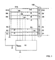
- FIG. 1 shown embodiment of the invention
- FIG. 1 schematically shows a battery pack 100 having a plurality of individual battery cells Zi each having at least substantially the same nominal cell voltage, in the illustrated case, for example, a first to tenth cell Z1, ... Z10, which are connected in series, wherein the outer Connections of the series circuit (ie, the positive pole of the tenth cell Z10 or the negative pole of the first cell Z1) form a positive pole (+) or a negative pole (-) of the battery pack 100.
- the Negative pole should represent the reference potential for the measurements of the voltages.
- the device according to the invention comprises a first to tenth measuring resistor R1, ... R10 each having the same resistance, which are connected in series, and a first to tenth switches S1, ... S10, via the respective connection between a positive pole of one of the cells Z1, ... Z10 and the respective parallel switchable measuring resistor R1, ... R10 can be produced.
- the measuring and control device 10 is shown, which in each case has a switching output for actuating each switch S1,... S10.
- the measuring and control device 10 further comprises a voltage measuring input to which the measuring voltage V mess falling across the first measuring resistor R 1 is supplied for measurement.
- the measuring and control device 10 is preferably constructed by means of a microprocessor.
- the switches S1,... S10 are preferably designed in the form of switchable semiconductor switches, such as, for example, bipolar transistors, MOSFETs or the like.
- FIG. 1 are finally indicated by dashed lines first to tenth currents I1, ... I10, each of the positive pole of one of the cells Z1, ... Z10 via the associated (closed) switch S1, ... S10 and the associated series circuit of Measuring resistors R1, ... R10 flow to ground.
- the switch on this cell ie the associated with the positive pole of this cell to be measured (associated) switch S1, ... S9 closed.
- At least one further switch is connected to a cell with a voltage which is higher in relation to the reference potential, preferably the switch on the cell with the highest voltage, at FIG. 1 embodiment shown so the tenth switch S10, also closed.
- the switches of all cells with a higher voltage than the cell to be measured could also be closed. All other switches remain or are opened.
- the tenth switch S10 is closed as a further switch, it is achieved that, starting from a balanced battery pack 100, due to the common same measuring current I10, all cells Z1,... Z10 and all measuring resistors R10,. ..R1 set the same voltages across all cells Z1, ... Z10.
- the current flowing through the closed switch Si of the cell to be measured is minimal or substantially zero. Since the same current flows through each cell Z1, ... Z10 at each instant, the measurement does not cause a debalancing.
- a possible debalancierter state of the cells is largely balanced by the device according to the invention.
- the eighth current I8 concerned by this eighth switch S8 is substantially equal to zero.
- the measuring current I10 is further guided only by the tenth switch S10 and the series connection of the measuring resistors R10, ... R1. Since this measuring current also flows through all the cells Z1,... Z10, the battery pack 100 is not debalanced.
- the cell voltage across a certain cell Z1,... Z10 is determined by subtracting two measuring voltages V mess , which drop off at the first measuring resistor R1, and taking into account the respective voltage dividing ratios due to the measuring resistors Ri as follows.
- the tenth switch S10 is closed by means of the measuring and control device 10, and preferably the tenth switch S10, as explained above. Then, by means of the measuring and control device 10, the voltage drop across the first measuring resistor R1, ie the measuring voltage V mess, is measured and stored. Subsequently, the eighth switch S8 is opened and the seventh switch S7 is closed. Now again, by means of the measuring and control device 10, the measuring voltage V mess is measured and stored at the first measuring resistor R1.
- the measuring voltage V mess measured after the closing of the eighth switch S8 is then multiplied by means of the measuring and control device 10 with the voltage divider ratio (R1 + R2 +... R8) / R1, so that the values across the series connection of the resistors R1 to R8 and thus results in the sum voltage across the cells Z1 to Z8 connected in series.
- the two above-mentioned voltage divider ratios are preferably stored in the measuring and control device 10 for all measuring voltages, so that they do not have to be recalculated for each measurement.
- the measuring and control device 10 is preferably designed so that a user can select or enter a cell to be measured, and the measuring and control device 10 then opens or closes the respective switches in accordance with the above-described method and the above calculated and displayed cell voltage lying selected cell.
- the measuring and control device 10 has for this purpose preferably a correspondingly programmed microprocessor unit, a memory and an input and output device.
- the resistance values of the series-connected measuring resistors R1,... R10 must be correspondingly adjusted in accordance with the voltage ratios of the cell voltages such that the same voltage drops across each measuring resistor as at the cell in parallel when the tenth switch is closed and all other switches are open.
- the device according to the invention can advantageously be used, for example, in combination with a charger to monitor the state of the individual cells during a charging / discharging process.
Landscapes
- Physics & Mathematics (AREA)
- General Physics & Mathematics (AREA)
- Secondary Cells (AREA)
- Charge And Discharge Circuits For Batteries Or The Like (AREA)
- Measurement Of Current Or Voltage (AREA)
Claims (7)
- Procédé pour mesurer des tensions d'éléments d'accumulateur parmi plusieurs éléments d'accumulateur montés en série avec un potentiel de référence commun, avec un nombre de résistances de mesure (Ri) montées en série qui correspond au nombre d'éléments (Zi) à mesurer, et avec un nombre d'interrupteurs (S) entre les résistances de mesure et les éléments, par l'intermédiaire desquels, lorsqu'ils se ferment, l'une des résistances de mesure est apte à être reliée en parallèle à l'un des éléments, avec les étapes qui consistent :- à fermer l'interrupteur relié à un premier pôle d'un élément à mesurer, ainsi qu'un autre interrupteur au niveau d'un pôle d'un élément avec une tension supérieure à celle de l'élément à mesurer, par rapport au potentiel de base, et à ouvrir éventuellement tous les autres interrupteurs,- à déterminer et stocker la tension qui baisse au niveau du premier pôle par rapport au potentiel de base ;- à ouvrir l'interrupteur relié au premier pôle de l'élément à mesurer, et à fermer l'interrupteur relié à un second pôle de l'élément à mesurer,- à déterminer et à stocker la tension qui baisse au niveau du second pôle par rapport au potentiel de référence,- à déterminer la tension d'élément en formant la différence entre les tensions déterminées au niveau des deux pôles.
- Procédé selon la revendication 1, selon lequel la tension qui baisse par rapport au potentiel de référence au niveau d'un pôle d'un élément (Zi) à mesurer est déterminée grâce au fait que la tension qui baisse par l'intermédiaire d'une première résistance de mesure (R1) du montage en série de résistances de mesure (Ri) reliée au potentiel de base est mesurée et, à partir de là, la tension qui baisse au niveau du pôle est calculée en tenant compte du rapport de division entre le montage en série de résistances de mesure qui est placé entre le pôle et le potentiel de référence, et la première résistance de mesure (R1).
- Procédé selon la revendication 2, selon lequel l'ouverture et la fermeture des interrupteurs (Si), le calcul des tensions qui baissent au niveau des pôles d'un élément (Zi) à mesurer ainsi que le calcul de la tension d'élément se font à l'aide d'un dispositif de mesure et de commande (10) commandé par microprocesseur.
- Dispositif pour mesurer des tensions d'éléments d'accumulateur parmi plusieurs éléments d'accumulateur (Zi) montés en série avec un potentiel de référence commun, avec :- un nombre de résistances de mesure (Ri) montées en série qui correspond au nombre d'éléments (Zi) à mesurer,- un nombre d'interrupteurs (Si) entre les résistances de mesure et les éléments ou raccordements pour les éléments, par l'intermédiaire desquels, lorsqu'ils se ferment, l'une des résistances de mesure est apte à être reliée en parallèle à l'un des éléments, et- un dispositif de mesure et de commande (10) pour ouvrir et fermer les interrupteurs (Si) en fonction d'un élément à mesurer choisi, et pour déterminer la tension de l'élément en formant la différence des tensions qui baissent par rapport au potentiel de référence au niveau des deux pôles de l'élément, selon un procédé selon l'une des revendications 1 à 3.
- Dispositif selon la revendication 4, selon lequel le dispositif de mesure et de commande (10) comporte une unité de calcul et/ou une unité de stockage pour calculer et stocker au moins un rapport de division de tension entre un montage en série de résistances de mesure (R1+R2+R3...) à monter entre un pôle d'un élément (Zi) à mesurer et le potentiel de référence, et une première résistance de mesure (R1) reliée au potentiel de référence.
- Dispositif selon la revendication 4 ou 5, selon lequel le dispositif de mesure et de commande (10) comporte une unité de microprocesseur et une mémoire pour relever et stocker la tension de mesure (Vmess) appliquée à son entrée, pour ouvrir et fermer les interrupteurs (Si) en fonction d'un élément à mesurer, sélectionné par l'utilisateur, et pour calculer la tension d'élément, selon un procédé selon l'une des revendications 1 à 3.
- Chargeur avec un dispositif selon l'une des revendications 4 à 6.
Applications Claiming Priority (2)
| Application Number | Priority Date | Filing Date | Title |
|---|---|---|---|
| DE102007049528A DE102007049528B4 (de) | 2007-10-15 | 2007-10-15 | Verfahren und Vorrichtung zur Messung von Zellenspannungen in einer Mehrzahl von in Reihe geschalteten Akkumulatorzellen |
| PCT/DE2008/001649 WO2009049592A1 (fr) | 2007-10-15 | 2008-10-14 | Procédé et dispositif de mesure de tensions de batteries dans une pluralité de batteries d'accumulateur montées en série |
Publications (2)
| Publication Number | Publication Date |
|---|---|
| EP2201397A1 EP2201397A1 (fr) | 2010-06-30 |
| EP2201397B1 true EP2201397B1 (fr) | 2011-07-06 |
Family
ID=40386422
Family Applications (1)
| Application Number | Title | Priority Date | Filing Date |
|---|---|---|---|
| EP08838816A Active EP2201397B1 (fr) | 2007-10-15 | 2008-10-14 | Procédé et dispositif de mesure de tensions de batteries dans une pluralité de batteries d'accumulateur montées en série |
Country Status (7)
| Country | Link |
|---|---|
| US (1) | US8242746B2 (fr) |
| EP (1) | EP2201397B1 (fr) |
| JP (1) | JP5577253B2 (fr) |
| CN (1) | CN101828123B (fr) |
| AT (1) | ATE515709T1 (fr) |
| DE (2) | DE102007049528B4 (fr) |
| WO (1) | WO2009049592A1 (fr) |
Families Citing this family (24)
| Publication number | Priority date | Publication date | Assignee | Title |
|---|---|---|---|---|
| US8421467B2 (en) * | 2009-11-19 | 2013-04-16 | Valence Technology, Inc. | Battery insulation resistance measurement methods, insulation resistance measurement methods, insulation resistance determination apparatuses, and articles of manufacture |
| JP6030817B2 (ja) * | 2010-06-04 | 2016-11-24 | エスアイアイ・セミコンダクタ株式会社 | バッテリ状態監視回路およびバッテリ装置 |
| CN101865945B (zh) * | 2010-06-11 | 2013-05-15 | 李小平 | 机械扫描式串联电池组电压检测方法及系统 |
| DE102010034510A1 (de) | 2010-08-16 | 2012-02-16 | Atmel Automotive Gmbh | Schaltung zur Überwachung von in Reihe geschalteten Akkumulatorzellen |
| JP4898982B1 (ja) * | 2010-08-31 | 2012-03-21 | パナソニック株式会社 | 電池電源装置、及び電池電源システム |
| US8470464B2 (en) | 2010-10-14 | 2013-06-25 | Alliant Techsystems Inc. | Methods and apparatuses for electrochemical cell monitoring and control |
| USD660788S1 (en) | 2011-03-04 | 2012-05-29 | Blount, Inc. | Battery |
| US9945910B2 (en) * | 2011-03-31 | 2018-04-17 | Renesas Electronics Corporation | Voltage monitoring module and voltage monitoring system which compares voltages to determine leakage |
| US9065296B2 (en) * | 2012-04-03 | 2015-06-23 | Samsung Sdi Co., Ltd. | Battery pack, method of measuring voltage of the battery pack, and energy storage system including the battery pack |
| CN102608512B (zh) * | 2012-04-11 | 2014-07-09 | 上海电力学院 | 在线检测太阳能光伏电站中光伏电池故障的方法 |
| US9231407B2 (en) * | 2012-05-07 | 2016-01-05 | Samsung Sdi Co., Ltd. | Battery system, method of controlling the same, and energy storage system including the battery system |
| JP2015191878A (ja) * | 2014-03-31 | 2015-11-02 | 株式会社日立製作所 | リチウムイオン二次電池システムおよびリチウムイオン二次電池の状態診断方法 |
| JP7049115B2 (ja) * | 2015-09-17 | 2022-04-06 | ヌヴォトンテクノロジージャパン株式会社 | 異常検出装置、及び電池システム |
| DE102015219828A1 (de) * | 2015-10-13 | 2017-04-13 | Robert Bosch Gmbh | Fortbewegungsmittel, Vorrichtung und Verfahren zur Ermittlung einer Spannung einer Zelle eines Strangs mehrerer in Reihe geschalteter Zellen eines elektrochemischen Energiespeichers |
| DE102015219822A1 (de) * | 2015-10-13 | 2017-04-13 | Robert Bosch Gmbh | Vorrichtung, Anordnung und elektrisch antreibbares Fortbewegungsmittel zur Spannungsüberwachung einer Vielzahl elektrochemischer Zellen eines Energiespeichers |
| KR102523045B1 (ko) * | 2016-01-12 | 2023-04-17 | 삼성전자주식회사 | 고장 셀 검출 장치 및 방법 |
| DE102016001057A1 (de) | 2016-01-30 | 2017-08-03 | Andreas Stihl Ag & Co. Kg | Schaltungsanordnung zur Bestimmung der Zellspannung einer Einzelzelle in einem Zellverbund |
| DE102016209822A1 (de) * | 2016-06-03 | 2017-12-07 | Robert Bosch Gmbh | Akkupack für eine Handwerkzeugmaschine und/oder ein Ladegerät |
| KR102236384B1 (ko) | 2017-10-27 | 2021-04-05 | 주식회사 엘지화학 | 배터리 밸런싱을 위한 장치 및 그것을 포함하는 배터리팩 |
| KR102256602B1 (ko) * | 2017-12-14 | 2021-05-26 | 주식회사 엘지에너지솔루션 | 전압 측정 장치 및 방법 |
| EP4166962B1 (fr) * | 2021-10-15 | 2024-06-19 | Andreas Stihl AG & Co. KG | Accumulateur d'énergie électrique |
| CN115004042B (zh) * | 2022-04-20 | 2025-01-14 | 香港应用科技研究院有限公司 | 用于低压cmos工艺的低功率电压检测器 |
| DE102024132047B3 (de) | 2024-11-04 | 2026-03-26 | Andreas Stihl Ag & Co. Kg | Elektrischer Energiespeicher, System aufweisend den Energiespeicher und Verfahren zu einer Ansteuerung elektrischer Messschalter und eines elektrischen Angleichungsschalters des Energiespeichers |
| CN119619877B (zh) * | 2024-11-19 | 2025-11-07 | 国网湖北省电力有限公司黄冈供电公司 | 一种用于蓄电池组在线监控的装置及其使用方法 |
Family Cites Families (13)
| Publication number | Priority date | Publication date | Assignee | Title |
|---|---|---|---|---|
| US5313152A (en) * | 1992-06-19 | 1994-05-17 | Ford Motor Company | Network for minimizing current imbalances in a faradaic battery |
| US5825155A (en) * | 1993-08-09 | 1998-10-20 | Kabushiki Kaisha Toshiba | Battery set structure and charge/ discharge control apparatus for lithium-ion battery |
| US5546003A (en) * | 1994-03-07 | 1996-08-13 | Polytronics Engineering Ltd. | Multi-cell battery monitoring system with single sensor wire |
| JP3197426B2 (ja) * | 1994-04-07 | 2001-08-13 | 株式会社マキタ | 充電装置 |
| JPH09318679A (ja) * | 1996-05-27 | 1997-12-12 | Honda Motor Co Ltd | 電気自動車の電源電圧検出装置 |
| JP4022797B2 (ja) * | 1999-03-29 | 2007-12-19 | 株式会社ジーエス・ユアサコーポレーション | 群電池の容量平準化回路 |
| JP3430083B2 (ja) | 1999-10-21 | 2003-07-28 | 本田技研工業株式会社 | 電池電圧測定装置 |
| JP4186393B2 (ja) * | 2000-07-26 | 2008-11-26 | 株式会社デンソー | 電池電圧検出装置 |
| JP3791767B2 (ja) * | 2001-03-27 | 2006-06-28 | 株式会社デンソー | フライングキャパシタ式電圧検出回路 |
| JP2003333763A (ja) | 2002-05-10 | 2003-11-21 | Toyota Motor Corp | 蓄電池制御装置 |
| US6873134B2 (en) * | 2003-07-21 | 2005-03-29 | The Boeing Company | Autonomous battery cell balancing system with integrated voltage monitoring |
| DE10347110B3 (de) * | 2003-10-10 | 2005-01-13 | Siemens Ag | Vorrichtung und Verfahren zum Messen einzelner Zellenspannungen in einem Zellenstapel eines Energiespeichers |
| JP2007040842A (ja) * | 2005-08-03 | 2007-02-15 | Matsushita Electric Ind Co Ltd | 電圧計測装置及び電動工具 |
-
2007
- 2007-10-15 DE DE102007049528A patent/DE102007049528B4/de not_active Expired - Fee Related
-
2008
- 2008-10-14 US US12/682,967 patent/US8242746B2/en active Active
- 2008-10-14 WO PCT/DE2008/001649 patent/WO2009049592A1/fr not_active Ceased
- 2008-10-14 DE DE112008003442T patent/DE112008003442A5/de not_active Withdrawn
- 2008-10-14 AT AT08838816T patent/ATE515709T1/de active
- 2008-10-14 EP EP08838816A patent/EP2201397B1/fr active Active
- 2008-10-14 JP JP2010529228A patent/JP5577253B2/ja active Active
- 2008-10-14 CN CN200880111787.1A patent/CN101828123B/zh active Active
Also Published As
| Publication number | Publication date |
|---|---|
| CN101828123B (zh) | 2014-05-14 |
| EP2201397A1 (fr) | 2010-06-30 |
| JP2011501808A (ja) | 2011-01-13 |
| JP5577253B2 (ja) | 2014-08-20 |
| CN101828123A (zh) | 2010-09-08 |
| DE102007049528A1 (de) | 2009-04-23 |
| ATE515709T1 (de) | 2011-07-15 |
| US20100219837A1 (en) | 2010-09-02 |
| US8242746B2 (en) | 2012-08-14 |
| WO2009049592A1 (fr) | 2009-04-23 |
| DE102007049528B4 (de) | 2009-06-25 |
| DE112008003442A5 (de) | 2010-09-16 |
Similar Documents
| Publication | Publication Date | Title |
|---|---|---|
| EP2201397B1 (fr) | Procédé et dispositif de mesure de tensions de batteries dans une pluralité de batteries d'accumulateur montées en série | |
| DE10345057B4 (de) | Verfahren und Vorrichtung zur Bestimmung des Ladezustandes einer Batterie | |
| EP0188477B1 (fr) | Procede et installation de surveillance de l'etat de charge d'accumulateurs rechargeables | |
| EP2442125B1 (fr) | Procédé et dispositif de surveillance de la capacité maximale disponible d'une batterie | |
| EP1671142B1 (fr) | Dispositif et procede pour mesurer des tensions de cellule individuelles dans un empilement de cellules d'un accumulateur d'energie | |
| DE69836403T2 (de) | Verfahren zur Laderegelung und Lader für wiederaufladbare Batterie | |
| DE102005051317A1 (de) | Verfahren zum Kontrollieren der Leistung einer wiederaufladbaren Batterie und ein Stromversorgungsgerät | |
| EP0589287A2 (fr) | Procédé pour le chargement d'une batterie multicellulaire | |
| EP2482422A1 (fr) | Dispositif et procédé de surveillance et de mise en symétrie d'une pile d'accumulation d'énergie à plusieurs cellules | |
| DE102013219360A1 (de) | Energiespeichereinrichtung | |
| DE102010021176A1 (de) | Anordnung zur Einzelzellenmessung in einem Akkupack und einem Akkupack mit einer solchen Anordnung | |
| EP2944009A2 (fr) | Procédé et dispositif destinés à augmenter la capacité disponible d'un groupe accumulateur par équilibrage des niveaux de charge des éléments, système de gestion d'accumulateur, accumulateur et appareil de charge d'accumulateur | |
| DE102019200510A1 (de) | Messanordnung, Hochvoltbatterie, Kraftfahrzeug und Verfahren zum Bestimmen einer komplexen Impedanz | |
| DE102020209396A1 (de) | Verfahren zur Erfassung von elektrischen Fehlerzuständen in einem Wechselakkupack und System zur Durchführung des Verfahrens | |
| DE102020209397A1 (de) | Verfahren zur Erfassung von elektrischen Fehlerzuständen eines Wechselakkupacks sowie System zur Durchführung des Verfahrens | |
| EP2556576A2 (fr) | Procédé et dispositif pour charger une batterie | |
| DE69922938T2 (de) | Spannungsanzeiger zum anzeigen der uberschreitung eines bestimmten wertes einer batteriespannung | |
| DE102021212799A1 (de) | Verfahren zum Laden oder Entladen eines wechselbaren Energiespeichers mittels eines Elektrogeräts sowie System mit einem wechselbaren Energiespeicher und einem Elektrogerät zur Durchführung des Verfahrens | |
| EP2208278A1 (fr) | Chargeur pour charger au moins un accumulateur d'énergie rechargeable | |
| EP3929595A1 (fr) | Borne de mesure d'énergie ou circuit de mesure d'une borne de mesure d'énergie | |
| DE102020209398A1 (de) | Verfahren zur Erfassung von elektrischen Fehlerzuständen eines Wechselakkupacks und/oder eines mit dem Wechselakkupack verbindbaren Elektrogeräts sowie System zur Durchführung des Verfahrens | |
| DE19918529B4 (de) | Verfahren und Vorrichtung zur Bestimmung des Ladezustands und/oder der aktuellen Kapazität einer Batterie | |
| DE102013215731A1 (de) | Verfahren und Vorrichtung zur Messung eines oder mehrerer Isolationswiderstände in einem Kraftfahrzeug | |
| DE102020216369A1 (de) | Wechselakkupack mit zumindest einem Schaltelement zur Unterbrechung bzw. Ermöglichung eines Lade- oder Entladestroms | |
| DE102018008610A1 (de) | Schaltungsanordnung zum Laden einer Batterieanordnung mit mehreren in Serie geschalteten Batterieschaltungen |
Legal Events
| Date | Code | Title | Description |
|---|---|---|---|
| PUAI | Public reference made under article 153(3) epc to a published international application that has entered the european phase |
Free format text: ORIGINAL CODE: 0009012 |
|
| 17P | Request for examination filed |
Effective date: 20100423 |
|
| AK | Designated contracting states |
Kind code of ref document: A1 Designated state(s): AT BE BG CH CY CZ DE DK EE ES FI FR GB GR HR HU IE IS IT LI LT LU LV MC MT NL NO PL PT RO SE SI SK TR |
|
| AX | Request for extension of the european patent |
Extension state: AL BA MK RS |
|
| DAX | Request for extension of the european patent (deleted) | ||
| GRAP | Despatch of communication of intention to grant a patent |
Free format text: ORIGINAL CODE: EPIDOSNIGR1 |
|
| GRAS | Grant fee paid |
Free format text: ORIGINAL CODE: EPIDOSNIGR3 |
|
| GRAA | (expected) grant |
Free format text: ORIGINAL CODE: 0009210 |
|
| AK | Designated contracting states |
Kind code of ref document: B1 Designated state(s): AT BE BG CH CY CZ DE DK EE ES FI FR GB GR HR HU IE IS IT LI LT LU LV MC MT NL NO PL PT RO SE SI SK TR |
|
| REG | Reference to a national code |
Ref country code: GB Ref legal event code: FG4D Free format text: NOT ENGLISH |
|
| REG | Reference to a national code |
Ref country code: CH Ref legal event code: EP |
|
| REG | Reference to a national code |
Ref country code: IE Ref legal event code: FG4D Free format text: LANGUAGE OF EP DOCUMENT: GERMAN |
|
| REG | Reference to a national code |
Ref country code: DE Ref legal event code: R096 Ref document number: 502008004142 Country of ref document: DE Effective date: 20110825 |
|
| REG | Reference to a national code |
Ref country code: NL Ref legal event code: VDEP Effective date: 20110706 |
|
| PG25 | Lapsed in a contracting state [announced via postgrant information from national office to epo] |
Ref country code: SI Free format text: LAPSE BECAUSE OF FAILURE TO SUBMIT A TRANSLATION OF THE DESCRIPTION OR TO PAY THE FEE WITHIN THE PRESCRIBED TIME-LIMIT Effective date: 20110706 |
|
| PG25 | Lapsed in a contracting state [announced via postgrant information from national office to epo] |
Ref country code: NO Free format text: LAPSE BECAUSE OF FAILURE TO SUBMIT A TRANSLATION OF THE DESCRIPTION OR TO PAY THE FEE WITHIN THE PRESCRIBED TIME-LIMIT Effective date: 20111006 Ref country code: LT Free format text: LAPSE BECAUSE OF FAILURE TO SUBMIT A TRANSLATION OF THE DESCRIPTION OR TO PAY THE FEE WITHIN THE PRESCRIBED TIME-LIMIT Effective date: 20110706 Ref country code: SE Free format text: LAPSE BECAUSE OF FAILURE TO SUBMIT A TRANSLATION OF THE DESCRIPTION OR TO PAY THE FEE WITHIN THE PRESCRIBED TIME-LIMIT Effective date: 20110706 Ref country code: NL Free format text: LAPSE BECAUSE OF FAILURE TO SUBMIT A TRANSLATION OF THE DESCRIPTION OR TO PAY THE FEE WITHIN THE PRESCRIBED TIME-LIMIT Effective date: 20110706 Ref country code: PT Free format text: LAPSE BECAUSE OF FAILURE TO SUBMIT A TRANSLATION OF THE DESCRIPTION OR TO PAY THE FEE WITHIN THE PRESCRIBED TIME-LIMIT Effective date: 20111107 Ref country code: IS Free format text: LAPSE BECAUSE OF FAILURE TO SUBMIT A TRANSLATION OF THE DESCRIPTION OR TO PAY THE FEE WITHIN THE PRESCRIBED TIME-LIMIT Effective date: 20111106 Ref country code: FI Free format text: LAPSE BECAUSE OF FAILURE TO SUBMIT A TRANSLATION OF THE DESCRIPTION OR TO PAY THE FEE WITHIN THE PRESCRIBED TIME-LIMIT Effective date: 20110706 Ref country code: HR Free format text: LAPSE BECAUSE OF FAILURE TO SUBMIT A TRANSLATION OF THE DESCRIPTION OR TO PAY THE FEE WITHIN THE PRESCRIBED TIME-LIMIT Effective date: 20110706 |
|
| REG | Reference to a national code |
Ref country code: IE Ref legal event code: FD4D |
|
| PG25 | Lapsed in a contracting state [announced via postgrant information from national office to epo] |
Ref country code: GR Free format text: LAPSE BECAUSE OF FAILURE TO SUBMIT A TRANSLATION OF THE DESCRIPTION OR TO PAY THE FEE WITHIN THE PRESCRIBED TIME-LIMIT Effective date: 20111007 Ref country code: CY Free format text: LAPSE BECAUSE OF FAILURE TO SUBMIT A TRANSLATION OF THE DESCRIPTION OR TO PAY THE FEE WITHIN THE PRESCRIBED TIME-LIMIT Effective date: 20110706 Ref country code: PL Free format text: LAPSE BECAUSE OF FAILURE TO SUBMIT A TRANSLATION OF THE DESCRIPTION OR TO PAY THE FEE WITHIN THE PRESCRIBED TIME-LIMIT Effective date: 20110706 Ref country code: LV Free format text: LAPSE BECAUSE OF FAILURE TO SUBMIT A TRANSLATION OF THE DESCRIPTION OR TO PAY THE FEE WITHIN THE PRESCRIBED TIME-LIMIT Effective date: 20110706 |
|
| BERE | Be: lapsed |
Owner name: ANDREAS STIHL A.G. & CO. KG Effective date: 20111031 |
|
| PG25 | Lapsed in a contracting state [announced via postgrant information from national office to epo] |
Ref country code: IE Free format text: LAPSE BECAUSE OF FAILURE TO SUBMIT A TRANSLATION OF THE DESCRIPTION OR TO PAY THE FEE WITHIN THE PRESCRIBED TIME-LIMIT Effective date: 20110706 Ref country code: CZ Free format text: LAPSE BECAUSE OF FAILURE TO SUBMIT A TRANSLATION OF THE DESCRIPTION OR TO PAY THE FEE WITHIN THE PRESCRIBED TIME-LIMIT Effective date: 20110706 Ref country code: SK Free format text: LAPSE BECAUSE OF FAILURE TO SUBMIT A TRANSLATION OF THE DESCRIPTION OR TO PAY THE FEE WITHIN THE PRESCRIBED TIME-LIMIT Effective date: 20110706 |
|
| PLBE | No opposition filed within time limit |
Free format text: ORIGINAL CODE: 0009261 |
|
| STAA | Information on the status of an ep patent application or granted ep patent |
Free format text: STATUS: NO OPPOSITION FILED WITHIN TIME LIMIT |
|
| PG25 | Lapsed in a contracting state [announced via postgrant information from national office to epo] |
Ref country code: MC Free format text: LAPSE BECAUSE OF NON-PAYMENT OF DUE FEES Effective date: 20111031 Ref country code: EE Free format text: LAPSE BECAUSE OF FAILURE TO SUBMIT A TRANSLATION OF THE DESCRIPTION OR TO PAY THE FEE WITHIN THE PRESCRIBED TIME-LIMIT Effective date: 20110706 Ref country code: IT Free format text: LAPSE BECAUSE OF FAILURE TO SUBMIT A TRANSLATION OF THE DESCRIPTION OR TO PAY THE FEE WITHIN THE PRESCRIBED TIME-LIMIT Effective date: 20110706 Ref country code: RO Free format text: LAPSE BECAUSE OF FAILURE TO SUBMIT A TRANSLATION OF THE DESCRIPTION OR TO PAY THE FEE WITHIN THE PRESCRIBED TIME-LIMIT Effective date: 20110706 |
|
| 26N | No opposition filed |
Effective date: 20120411 |
|
| PG25 | Lapsed in a contracting state [announced via postgrant information from national office to epo] |
Ref country code: DK Free format text: LAPSE BECAUSE OF FAILURE TO SUBMIT A TRANSLATION OF THE DESCRIPTION OR TO PAY THE FEE WITHIN THE PRESCRIBED TIME-LIMIT Effective date: 20110706 |
|
| PG25 | Lapsed in a contracting state [announced via postgrant information from national office to epo] |
Ref country code: BE Free format text: LAPSE BECAUSE OF NON-PAYMENT OF DUE FEES Effective date: 20111031 |
|
| REG | Reference to a national code |
Ref country code: DE Ref legal event code: R097 Ref document number: 502008004142 Country of ref document: DE Effective date: 20120411 |
|
| PG25 | Lapsed in a contracting state [announced via postgrant information from national office to epo] |
Ref country code: MT Free format text: LAPSE BECAUSE OF FAILURE TO SUBMIT A TRANSLATION OF THE DESCRIPTION OR TO PAY THE FEE WITHIN THE PRESCRIBED TIME-LIMIT Effective date: 20110706 |
|
| PG25 | Lapsed in a contracting state [announced via postgrant information from national office to epo] |
Ref country code: ES Free format text: LAPSE BECAUSE OF FAILURE TO SUBMIT A TRANSLATION OF THE DESCRIPTION OR TO PAY THE FEE WITHIN THE PRESCRIBED TIME-LIMIT Effective date: 20111017 |
|
| PG25 | Lapsed in a contracting state [announced via postgrant information from national office to epo] |
Ref country code: LU Free format text: LAPSE BECAUSE OF NON-PAYMENT OF DUE FEES Effective date: 20111014 |
|
| REG | Reference to a national code |
Ref country code: CH Ref legal event code: PL |
|
| PG25 | Lapsed in a contracting state [announced via postgrant information from national office to epo] |
Ref country code: BG Free format text: LAPSE BECAUSE OF FAILURE TO SUBMIT A TRANSLATION OF THE DESCRIPTION OR TO PAY THE FEE WITHIN THE PRESCRIBED TIME-LIMIT Effective date: 20111006 |
|
| PG25 | Lapsed in a contracting state [announced via postgrant information from national office to epo] |
Ref country code: LI Free format text: LAPSE BECAUSE OF NON-PAYMENT OF DUE FEES Effective date: 20121031 Ref country code: CH Free format text: LAPSE BECAUSE OF NON-PAYMENT OF DUE FEES Effective date: 20121031 |
|
| PG25 | Lapsed in a contracting state [announced via postgrant information from national office to epo] |
Ref country code: TR Free format text: LAPSE BECAUSE OF FAILURE TO SUBMIT A TRANSLATION OF THE DESCRIPTION OR TO PAY THE FEE WITHIN THE PRESCRIBED TIME-LIMIT Effective date: 20110706 |
|
| PG25 | Lapsed in a contracting state [announced via postgrant information from national office to epo] |
Ref country code: HU Free format text: LAPSE BECAUSE OF FAILURE TO SUBMIT A TRANSLATION OF THE DESCRIPTION OR TO PAY THE FEE WITHIN THE PRESCRIBED TIME-LIMIT Effective date: 20110706 |
|
| REG | Reference to a national code |
Ref country code: AT Ref legal event code: MM01 Ref document number: 515709 Country of ref document: AT Kind code of ref document: T Effective date: 20131014 |
|
| PG25 | Lapsed in a contracting state [announced via postgrant information from national office to epo] |
Ref country code: AT Free format text: LAPSE BECAUSE OF NON-PAYMENT OF DUE FEES Effective date: 20131014 |
|
| REG | Reference to a national code |
Ref country code: FR Ref legal event code: PLFP Year of fee payment: 8 |
|
| REG | Reference to a national code |
Ref country code: FR Ref legal event code: PLFP Year of fee payment: 9 |
|
| REG | Reference to a national code |
Ref country code: FR Ref legal event code: PLFP Year of fee payment: 10 |
|
| REG | Reference to a national code |
Ref country code: FR Ref legal event code: PLFP Year of fee payment: 11 |
|
| PGFP | Annual fee paid to national office [announced via postgrant information from national office to epo] |
Ref country code: GB Payment date: 20231024 Year of fee payment: 16 |
|
| GBPC | Gb: european patent ceased through non-payment of renewal fee |
Effective date: 20241014 |
|
| PG25 | Lapsed in a contracting state [announced via postgrant information from national office to epo] |
Ref country code: GB Free format text: LAPSE BECAUSE OF NON-PAYMENT OF DUE FEES Effective date: 20241014 |
|
| PGFP | Annual fee paid to national office [announced via postgrant information from national office to epo] |
Ref country code: DE Payment date: 20251028 Year of fee payment: 18 |
|
| PGFP | Annual fee paid to national office [announced via postgrant information from national office to epo] |
Ref country code: FR Payment date: 20251027 Year of fee payment: 18 |