EP2201397B1 - Method and device for measuring cell voltages in a plurality of series-connected accumulator cells - Google Patents
Method and device for measuring cell voltages in a plurality of series-connected accumulator cells Download PDFInfo
- Publication number
- EP2201397B1 EP2201397B1 EP08838816A EP08838816A EP2201397B1 EP 2201397 B1 EP2201397 B1 EP 2201397B1 EP 08838816 A EP08838816 A EP 08838816A EP 08838816 A EP08838816 A EP 08838816A EP 2201397 B1 EP2201397 B1 EP 2201397B1
- Authority
- EP
- European Patent Office
- Prior art keywords
- cell
- measuring
- voltage
- cells
- measured
- Prior art date
- Legal status (The legal status is an assumption and is not a legal conclusion. Google has not performed a legal analysis and makes no representation as to the accuracy of the status listed.)
- Active
Links
Images
Classifications
-
- G—PHYSICS
- G01—MEASURING; TESTING
- G01R—MEASURING ELECTRIC VARIABLES; MEASURING MAGNETIC VARIABLES
- G01R31/00—Arrangements for testing electric properties; Arrangements for locating electric faults; Arrangements for electrical testing characterised by what is being tested not provided for elsewhere
- G01R31/36—Arrangements for testing, measuring or monitoring the electrical condition of accumulators or electric batteries, e.g. capacity or state of charge [SoC]
- G01R31/382—Arrangements for monitoring battery or accumulator variables, e.g. SoC
- G01R31/3835—Arrangements for monitoring battery or accumulator variables, e.g. SoC involving only voltage measurements
-
- G—PHYSICS
- G01—MEASURING; TESTING
- G01R—MEASURING ELECTRIC VARIABLES; MEASURING MAGNETIC VARIABLES
- G01R31/00—Arrangements for testing electric properties; Arrangements for locating electric faults; Arrangements for electrical testing characterised by what is being tested not provided for elsewhere
- G01R31/36—Arrangements for testing, measuring or monitoring the electrical condition of accumulators or electric batteries, e.g. capacity or state of charge [SoC]
- G01R31/396—Acquisition or processing of data for testing or for monitoring individual cells or groups of cells within a battery
Definitions
- the invention relates to a method and a device for measuring cell voltages of accumulator cells in a plurality of series-connected accumulator cells, as used for example in so-called battery packs or cell packs such as LiIon cell packs.
- the invention further relates to a charger for a battery pack with such a device.
- Typical applications of these rechargeable battery packs are, for example, electric machine tools, hand-held household appliances such as e.g. Vacuum cleaners, flashlights, cleaning apparatus, or other garden, tree and shrub maintenance equipment.
- Battery packs of this and other types generally include a plurality of individual battery cells connected in series.
- the measurements of these cell voltages are generally carried out in relation to a common potential, in particular the negative pole of the series circuit or of the battery pack. This often causes the problem that during the measurements of the cell voltages, the individual cells are charged differently and thus out of balance. It has demonstrated that debalancing can reduce the effective capacity of the battery pack.
- the DE 103 47 110 an apparatus and method for measuring individual cell voltages in a cell stack of an energy storage described.
- a series circuit of two diodes is arranged in parallel to each cell, the connection points are connected via a respective capacitor and a switch with a differential amplifier.
- an alternating current of certain frequency and amplitude is fed, which generates an AC voltage corresponding to the cell voltage, which is converted after rectification to a mass-related DC voltage value for the cell voltage.
- a control device and a control method for a storage battery in which a first control device for releasing charges stored in a storage battery (capacitor) in the case where the terminal voltage of the storage battery is at or above a predetermined threshold, a temperature Detecting means for detecting the temperature of the storage battery, and a second control device is provided which changes the predetermined threshold value in dependence on the temperature of the storage battery.
- the DE 100 51 984 discloses a battery voltage measuring device, in particular for such battery cells, the are composed of a plurality of serially connected modules each having a plurality of serially connected secondary batteries.
- the device essentially comprises, for each module, a capacitor which is charged to the voltage of the relevant module, switches which connect and disconnect this capacitor and the module, a voltage follower which outputs the voltage across the capacitor, and switches which output the voltage Connect the voltage follower and the capacitor and disconnect. This is to detect the battery voltage with high accuracy.
- the measuring device essentially comprises a sampling switch for connecting one or more battery cells to be measured to a capacitor, so that it is charged by these battery cells, a measuring part which detects and corrects the voltage across the charged capacitor as a measuring voltage, so that the voltage supplied by the As well as an overvoltage protection switch, which is switched on immediately before the sampling switch is turned on and grounds the input terminal of the measuring part, so that the measuring part is protected from overvoltages.
- a sampling switch for connecting one or more battery cells to be measured to a capacitor, so that it is charged by these battery cells
- a measuring part which detects and corrects the voltage across the charged capacitor as a measuring voltage, so that the voltage supplied by the As well as an overvoltage protection switch, which is switched on immediately before the sampling switch is turned on and grounds the input terminal of the measuring part, so that the measuring part is protected from overvoltages.
- An object on which the invention is based is to provide a method and a device for measuring cell voltages of accumulator cells in a plurality of serially connected accumulator cells (in particular in a battery pack), with which / by the Measurements of the cell voltages at the individual cells caused debalancing of the cell series connection can be at least substantially reduced.
- a particular advantage of these solutions is that debalancing can be reduced at least to such an extent that, in contrast to known solutions, they no longer have a relevant influence on the immunity to interference, the measurement accuracy, the sampling time, the reaction time, the measuring time or other parameters.
- the measuring resistors Ri and switches Si are thus arranged so that a measuring resistor Ri can be connected in parallel to each cell Zi to be measured and all measuring resistors Ri are connected in series.
- the series connection of the measuring resistors is connected in parallel to the series connection of the cells, that is, the two outer terminals of the series connection of the measuring resistors are respectively connected to the outer terminals of the series connection of the cells.
- One of the two outer terminals of the cell series circuit (preferably the negative pole) forms the reference potential for the measurements of the cell voltages across the cells, so that in this connection to the respective outer terminal of the series connection of the measuring resistors due to the common reference potential no switch to be present needs.
- the measuring resistors Ri are all the same size, provided that the rated voltages of the individual cells Zi are all the same size. If one of the cells has a higher rated voltage than the other cells, the measuring resistor which can be switched in parallel to this cell must also be dimensioned to be larger in the same ratio than the series-connected measuring resistors which can be connected in parallel with the other cells.
- the device according to the invention further comprises a measuring and control device, with the switch according to the inventive method Si depending on the cell whose cell voltage is to be determined opened or are closed in order to then calculate the cell voltage from the measured voltages dropping across one of the measuring resistors Ri.
- a cell voltage across a cell to be measured is determined by subtraction of those voltages which are present at the two poles of the cell to be measured with respect to the reference potential.
- the (measuring) voltage dropping across that measuring resistor is preferably measured, which is connected to the reference potential by one of its terminals (which also represents an external terminal of the series circuit) ("first" measuring resistor R1).
- the two voltages at the poles of the cell to be measured are determined in each case taking into account the divider ratio between the lying between the respective pole of the cell to be measured and the reference potential series connection of the measuring resistors and the first measuring resistor.
- the switch connected to this pole is closed by means of the measuring and control device. Furthermore, at least one further switch is closed at one pole of a cell with a voltage which is higher than the reference potential, in comparison with the cell to be measured, preferably the switch with the highest voltage (generally the switch on the positive pole of the cell series connection). All other switches are open. (In addition, it should be noted that in the case where the positive pole is selected as reference potential, a switch is closed at one pole of a cell with a magnitude higher than the reference potential compared to the cell to be measured, preferably the switch at the negative terminal cell series).
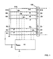
- FIG. 1 shown embodiment of the invention
- FIG. 1 schematically shows a battery pack 100 having a plurality of individual battery cells Zi each having at least substantially the same nominal cell voltage, in the illustrated case, for example, a first to tenth cell Z1, ... Z10, which are connected in series, wherein the outer Connections of the series circuit (ie, the positive pole of the tenth cell Z10 or the negative pole of the first cell Z1) form a positive pole (+) or a negative pole (-) of the battery pack 100.
- the Negative pole should represent the reference potential for the measurements of the voltages.
- the device according to the invention comprises a first to tenth measuring resistor R1, ... R10 each having the same resistance, which are connected in series, and a first to tenth switches S1, ... S10, via the respective connection between a positive pole of one of the cells Z1, ... Z10 and the respective parallel switchable measuring resistor R1, ... R10 can be produced.
- the measuring and control device 10 is shown, which in each case has a switching output for actuating each switch S1,... S10.
- the measuring and control device 10 further comprises a voltage measuring input to which the measuring voltage V mess falling across the first measuring resistor R 1 is supplied for measurement.
- the measuring and control device 10 is preferably constructed by means of a microprocessor.
- the switches S1,... S10 are preferably designed in the form of switchable semiconductor switches, such as, for example, bipolar transistors, MOSFETs or the like.
- FIG. 1 are finally indicated by dashed lines first to tenth currents I1, ... I10, each of the positive pole of one of the cells Z1, ... Z10 via the associated (closed) switch S1, ... S10 and the associated series circuit of Measuring resistors R1, ... R10 flow to ground.
- the switch on this cell ie the associated with the positive pole of this cell to be measured (associated) switch S1, ... S9 closed.
- At least one further switch is connected to a cell with a voltage which is higher in relation to the reference potential, preferably the switch on the cell with the highest voltage, at FIG. 1 embodiment shown so the tenth switch S10, also closed.
- the switches of all cells with a higher voltage than the cell to be measured could also be closed. All other switches remain or are opened.
- the tenth switch S10 is closed as a further switch, it is achieved that, starting from a balanced battery pack 100, due to the common same measuring current I10, all cells Z1,... Z10 and all measuring resistors R10,. ..R1 set the same voltages across all cells Z1, ... Z10.
- the current flowing through the closed switch Si of the cell to be measured is minimal or substantially zero. Since the same current flows through each cell Z1, ... Z10 at each instant, the measurement does not cause a debalancing.
- a possible debalancierter state of the cells is largely balanced by the device according to the invention.
- the eighth current I8 concerned by this eighth switch S8 is substantially equal to zero.
- the measuring current I10 is further guided only by the tenth switch S10 and the series connection of the measuring resistors R10, ... R1. Since this measuring current also flows through all the cells Z1,... Z10, the battery pack 100 is not debalanced.
- the cell voltage across a certain cell Z1,... Z10 is determined by subtracting two measuring voltages V mess , which drop off at the first measuring resistor R1, and taking into account the respective voltage dividing ratios due to the measuring resistors Ri as follows.
- the tenth switch S10 is closed by means of the measuring and control device 10, and preferably the tenth switch S10, as explained above. Then, by means of the measuring and control device 10, the voltage drop across the first measuring resistor R1, ie the measuring voltage V mess, is measured and stored. Subsequently, the eighth switch S8 is opened and the seventh switch S7 is closed. Now again, by means of the measuring and control device 10, the measuring voltage V mess is measured and stored at the first measuring resistor R1.
- the measuring voltage V mess measured after the closing of the eighth switch S8 is then multiplied by means of the measuring and control device 10 with the voltage divider ratio (R1 + R2 +... R8) / R1, so that the values across the series connection of the resistors R1 to R8 and thus results in the sum voltage across the cells Z1 to Z8 connected in series.
- the two above-mentioned voltage divider ratios are preferably stored in the measuring and control device 10 for all measuring voltages, so that they do not have to be recalculated for each measurement.
- the measuring and control device 10 is preferably designed so that a user can select or enter a cell to be measured, and the measuring and control device 10 then opens or closes the respective switches in accordance with the above-described method and the above calculated and displayed cell voltage lying selected cell.
- the measuring and control device 10 has for this purpose preferably a correspondingly programmed microprocessor unit, a memory and an input and output device.
- the resistance values of the series-connected measuring resistors R1,... R10 must be correspondingly adjusted in accordance with the voltage ratios of the cell voltages such that the same voltage drops across each measuring resistor as at the cell in parallel when the tenth switch is closed and all other switches are open.
- the device according to the invention can advantageously be used, for example, in combination with a charger to monitor the state of the individual cells during a charging / discharging process.
Landscapes
- Physics & Mathematics (AREA)
- General Physics & Mathematics (AREA)
- Secondary Cells (AREA)
- Charge And Discharge Circuits For Batteries Or The Like (AREA)
- Measurement Of Current Or Voltage (AREA)
Abstract
Description
Die Erfindung betrifft ein Verfahren und eine Vorrichtung zur Messung von Zellenspannungen von Akkumulatorzellen in einer Mehrzahl von in Reihe geschalteten Akkumulatorzellen, wie sie zum Beispiel in sogenannten Akkupacks oder Zellenpacks wie LiIon-Zellenpacks verwendet werden. Die Erfindung betrifft ferner ein Ladegerät für ein Akkupack mit einer solchen Vorrichtung.The invention relates to a method and a device for measuring cell voltages of accumulator cells in a plurality of series-connected accumulator cells, as used for example in so-called battery packs or cell packs such as LiIon cell packs. The invention further relates to a charger for a battery pack with such a device.
Typische Einsatzgebiete dieser wieder aufladbaren Akkupacks sind zum Beispiel elektrische Werkzeugmaschinen, handgeführte Haushaltsgeräte wie z.B. Staubsauger, Taschenlampen, Reinigungsgeräte, oder andere Geräte zur Garten-, Baum- und Strauchpflege.Typical applications of these rechargeable battery packs are, for example, electric machine tools, hand-held household appliances such as e.g. Vacuum cleaners, flashlights, cleaning apparatus, or other garden, tree and shrub maintenance equipment.
Akkupacks dieser und anderer Art enthalten im Allgemeinen eine Mehrzahl von in Reihe geschalteten einzelnen Akkumulatorzellen. Insbesondere bei LiIon-Akkupacks besteht dabei häufig die Notwendigkeit, die Spannungen über den einzelnen, in Reihe (d.h. seriell) geschalteten Zellen (sog. Einzel- oder Zellenspannung) zu messen, um damit zum Beispiel Kapazitätszustände des Akkupacks zu ermitteln oder Lade/Entladezyklen optimal steuern zu können.Battery packs of this and other types generally include a plurality of individual battery cells connected in series. In the case of LiIon battery packs in particular, there is often the necessity of measuring the voltages across the individual cells connected in series (ie, serial) (so-called single or cell voltage), in order to determine, for example, capacity states of the battery pack or optimal charging / discharging cycles to be able to control.
Die Messungen dieser Zellenspannungen erfolgen im Allgemeinen in Bezug auf ein gemeinsames Potential, insbesondere den Minuspol der Reihenschaltung bzw. des Akkupacks. Hierbei entsteht häufig das Problem, dass während der Messungen der Zellenspannungen die einzelnen Zellen unterschiedlich stark belastet und somit außer Balance gebracht werden. Es hat sich gezeigt, dass sich durch diese Debalancierung die effektive Kapazität des Akkupacks vermindern kann.The measurements of these cell voltages are generally carried out in relation to a common potential, in particular the negative pole of the series circuit or of the battery pack. This often causes the problem that during the measurements of the cell voltages, the individual cells are charged differently and thus out of balance. It has demonstrated that debalancing can reduce the effective capacity of the battery pack.
So wird z.B. in der
Aus der
Die
In der
Aus der
Eine Aufgabe, die der Erfindung zu Grunde liegt, besteht deshalb darin, ein Verfahren und eine Vorrichtung zur Messung von Zellenspannungen von Akkumulatorzellen in einer Mehrzahl von in Reihe geschalteten Akkumulatorzellen (insbesondere in einem Akkupack) zu schaffen, mit dem/der die durch die genannten Messungen der Zellenspannungen an den einzelnen Zellen verursachte Debalancierung der Zellen-Reihenschaltung zumindest wesentlich vermindert werden kann.An object on which the invention is based, therefore, is to provide a method and a device for measuring cell voltages of accumulator cells in a plurality of serially connected accumulator cells (in particular in a battery pack), with which / by the Measurements of the cell voltages at the individual cells caused debalancing of the cell series connection can be at least substantially reduced.
Gelöst wird diese Aufgabe gemäß Anspruch 1 mit einem Verfahren zur Messung von Zellenspannungen von Akkumulatorzellen in einer Mehrzahl von in Reihe geschalteten Akkumulatorzellen mit einem gemeinsamen Bezugspotential, mit einer der Anzahl von zu messenden Zellen entsprechenden Anzahl von in Reihe geschalteten Messwiderständen, sowie einer Anzahl von Schaltern zwischen den Messwiderständen und den Zellen, über die durch Schließen jeweils einer der Messwiderstände zu einer der Zellen parallel schaltbar ist, mit folgenden Schritten:
- Schließen des mit einem ersten Pol einer zu messenden Zelle verbundenen Schalters sowie eines weiteren Schalters an einem Pol einer Zelle mit einer im Vergleich zu der zu messenden Zelle betragsmäßig höheren Spannung gegenüber dem Bezugspotential, und gegebenenfalls Öffnen aller anderen Schalter,
- Ermitteln und Speichern der an dem ersten Pol gegenüber dem Bezugspotential abfallenden Spannung;
- Öffnen des mit dem ersten Pol der zu messenden Zelle verbundenen Schalters und Schließen des mit einem zweiten Pol der zu messenden Zelle verbundenen Schalters,
- Ermitteln und Speichern der an dem zweiten Pol gegenüber dem Bezugspotential abfallenden Spannung,
- Ermitteln der Zellenspannung durch Differenzbildung der über den beiden Polen ermittelten Spannungen.
- Closing the switch connected to a first pole of a cell to be measured as well as a further switch at one pole of a cell with a magnitude higher voltage than the reference potential compared to the cell to be measured, and optionally opening all other switches,
- Determining and storing the voltage drop across the first pole from the reference potential;
- Opening the switch connected to the first pole of the cell to be measured and closing the switch connected to a second pole of the cell to be measured,
- Determining and storing the voltage drop across the second pole from the reference potential,
- Determining the cell voltage by subtraction of the voltages detected across the two poles.
Die Aufgabe wird ferner gemäß Anspruch 4 mit einer Vorrichtung zur Messung von Zellenspannungen von Akkumulatorzellen in einer Mehrzahl von in Reihe geschalteten Akkumulatorzellen mit einem gemeinsamen Bezugspotential gelöst, wobei die Vorrichtung aufweist:
- eine der Anzahl von zu messenden Zellen entsprechende Anzahl von in Reihe geschalteten Messwiderständen,
- eine Anzahl von Schaltern zwischen den Messwiderständen und den Zellen oder Anschlüssen für die Zellen, über die durch Schließen jeweils einer der Messwiderstände zu einer der Zellen parallel schaltbar ist, sowie
- eine Mess- und Steuereinrichtung zum Öffnen bzw. Schließen der Schalter in Abhängigkeit von einer gewählten, zu messenden Zelle, sowie zur Ermittlung der Zellenspannung der Zelle durch Differenzbildung der über den beiden Polen der Zelle gegenüber dem Bezugspotential abfallenden Spannung gemäß dem oben genannten Verfahren.
- a number of measuring resistors connected in series, corresponding to the number of cells to be measured,
- a number of switches between the measuring resistors and the cells or terminals for the cells, which can be switched in parallel by closing one of the measuring resistors to one of the cells, as well as
- a measuring and control device for opening or closing the switch in dependence on a selected, to be measured cell, and for determining the cell voltage of the cell by subtraction of the voltage across the two poles of the cell relative to the reference potential voltage according to the above method.
Ein besonderer Vorteil dieser Lösungen besteht darin, dass damit eine Debalancierung zumindest so weit vermindert werden kann, dass diese im Gegensatz zu bekannten Lösungen keinen relevanten Einfluss mehr auf die Störsicherheit, die Messgenauigkeit, die Abtastzeit, die Reaktionszeit, die Messzeit oder andere Parameter hat.A particular advantage of these solutions is that debalancing can be reduced at least to such an extent that, in contrast to known solutions, they no longer have a relevant influence on the immunity to interference, the measurement accuracy, the sampling time, the reaction time, the measuring time or other parameters.
Weiterhin sind das erfindungsgemäße Verfahren und die erfindungsgemäße Vorrichtung zum Messen der Zellen von Akkupacks mit einer nahezu beliebigen Anzahl von Zellen anwendbar.Furthermore, the inventive method and apparatus for measuring the cells of battery packs with an almost any number of cells are applicable.
Die Unteransprüche haben vorteilhafte Weiterbildungen der Erfindung zum Inhalt.The dependent claims have advantageous developments of the invention to the content.
Weitere Einzelheiten, Merkmale und Vorteile der Erfindung ergeben sich aus der folgenden Beschreibung einer beispielhaften und bevorzugten Ausführungsform anhand der Zeichnung. Es zeigt:
-
Fig. 1 ein schematisches Blockschaltbild einer solchen bevorzugten Ausführungsform der Erfindung.
-
Fig. 1 a schematic block diagram of such a preferred embodiment of the invention.
Allgemein umfasst eine erfindungsgemäße Vorrichtung zur Messung von Zellenspannungen eine der Anzahl von zu messenden, in Reihe geschalteten Zellen Zi entsprechende Anzahl von in Reihe geschalteten Messwiderständen Ri, sowie zwischen den Messwiderständen und den Zellen eine Anzahl von Schaltern Si, über die durch Schließen jeweils einer der Messwiderstände parallel zu einer der Zellen geschaltet werden kann. Die Messwiderstände Ri und Schalter Si sind somit so angeordnet, dass zu jeder zu messenden Zelle Zi jeweils ein Messwiderstand Ri parallel geschaltet werden kann und alle Messwiderstände Ri in Reihe geschaltet sind.In general, a device according to the invention for measuring cell voltages comprises a number of series-connected measuring resistors Ri corresponding to the number of cells Zi connected in series, and a number of switches Si between the measuring resistors and the cells Measuring resistors can be connected in parallel to one of the cells. The measuring resistors Ri and switches Si are thus arranged so that a measuring resistor Ri can be connected in parallel to each cell Zi to be measured and all measuring resistors Ri are connected in series.
Die Reihenschaltung der Messwiderstände ist dabei parallel zu der Reihenschaltung der Zellen geschaltet, das heißt die beiden äußeren Anschlüsse der Reihenschaltung der Messwiderstände sind jeweils mit den äußeren Anschlüssen der Reihenschaltung der Zellen verbunden. Einer der beiden äußeren Anschlüsse der Zellen-Reihenschaltung (vorzugsweise der Minuspol) bildet das Bezugspotential für die Messungen der Zellenspannungen über den Zellen, so dass in dieser Verbindung zu dem betreffenden äußeren Anschluss der Reihenschaltung der Messwiderstände auf Grund des gemeinsamen Bezugspotentials kein Schalter vorhanden zu sein braucht.The series connection of the measuring resistors is connected in parallel to the series connection of the cells, that is, the two outer terminals of the series connection of the measuring resistors are respectively connected to the outer terminals of the series connection of the cells. One of the two outer terminals of the cell series circuit (preferably the negative pole) forms the reference potential for the measurements of the cell voltages across the cells, so that in this connection to the respective outer terminal of the series connection of the measuring resistors due to the common reference potential no switch to be present needs.
Der Vollständigkeit halber sei angemerkt, dass dies natürlich entsprechend auch in dem Fall gilt, in dem als Bezugspotential ein Nullpotential innerhalb der Reihenschaltung der Zellen gewählt und an den äußeren Anschlüssen der Reihenschaltung eine positive bzw. negative Spannung in Bezug auf das über einen entsprechenden dritten äußeren (z.B. mittleren) Anschluss herausgeführte Nullpotential zur Verfügung gestellt wird, so dass das erfindungsgemäße Prinzip auch in diesem Fall anwendbar ist.For the sake of completeness it should be noted that, of course, this also applies in the case in which selected as a reference potential, a zero potential within the series circuit of the cells and at the outer terminals of the series circuit, a positive or negative voltage with respect to a third third external (For example, middle) connection led zero potential is provided, so that the principle of the invention is also applicable in this case.
Die Messwiderstände Ri haben alle die gleiche Größe, sofern die Nennspannungen der einzelnen Zellen Zi auch alle jeweils gleich groß sind. Sofern eine der Zellen eine höhere Nennspannung aufweist, als die anderen Zellen, ist auch der zu dieser Zelle parallel schaltbare Messwiderstand im gleichen Verhältnis größer zu bemessen als die zu den anderen Zellen parallel schaltbaren Messwiderstände der Reihenschaltung.The measuring resistors Ri are all the same size, provided that the rated voltages of the individual cells Zi are all the same size. If one of the cells has a higher rated voltage than the other cells, the measuring resistor which can be switched in parallel to this cell must also be dimensioned to be larger in the same ratio than the series-connected measuring resistors which can be connected in parallel with the other cells.
Die erfindungsgemäße Vorrichtung umfasst weiterhin eine Mess- und Steuereinrichtung, mit der gemäß dem erfindungsgemäßen Verfahren die Schalter Si in Abhängigkeit von derjenigen Zelle, deren Zellenspannung ermittelt werden soll, geöffnet bzw. geschlossen werden, um dann aus den gemessenen, über einem der Messwiderstände Ri abfallenden Spannungen die Zellenspannung zu berechnen.The device according to the invention further comprises a measuring and control device, with the switch according to the inventive method Si depending on the cell whose cell voltage is to be determined opened or are closed in order to then calculate the cell voltage from the measured voltages dropping across one of the measuring resistors Ri.
Dabei wird eine Zellenspannung über einer zu messenden Zelle durch Differenzbildung derjenigen Spannungen ermittelt, die an den beiden Polen der zu messenden Zelle gegenüber dem Bezugspotenzial anliegen.In this case, a cell voltage across a cell to be measured is determined by subtraction of those voltages which are present at the two poles of the cell to be measured with respect to the reference potential.
Zur Ermittlung dieser beiden Spannungen wird vorzugsweise die über demjenigen Messwiderstand abfallende (Mess-)Spannung gemessen, der mit einem seiner Anschlüsse (der auch einen äußeren Anschluss der Reihenschaltung darstellt) mit dem Bezugspotential verbunden ist ("erster" Messwiderstand R1). Die beiden Spannungen an den Polen der zu messenden Zelle werden jeweils unter Berücksichtigung des Teilerverhältnisses zwischen der zwischen dem betreffenden Pol der zu messenden Zelle und dem Bezugspotential liegenden Reihenschaltung der Messwiderstände und dem ersten Messwiderstand ermittelt. Dies hat den Vorteil, dass der Messabgriff für die Messspannung bei der Ermittlung aller Zellenspannungen über allen Zellen der gleiche sein kann (nämlich an dem mit dem Bezugspotential verbundenen, ersten Messwiderstand R1) und somit nicht mittels weiterer Schalter o.ä. verändert werden muss.In order to determine these two voltages, the (measuring) voltage dropping across that measuring resistor is preferably measured, which is connected to the reference potential by one of its terminals (which also represents an external terminal of the series circuit) ("first" measuring resistor R1). The two voltages at the poles of the cell to be measured are determined in each case taking into account the divider ratio between the lying between the respective pole of the cell to be measured and the reference potential series connection of the measuring resistors and the first measuring resistor. This has the advantage that the measuring tap for the measuring voltage in the determination of all cell voltages across all cells can be the same (namely at the first measuring resistor R1 connected to the reference potential) and thus not by means of further switches or the like. must be changed.
Zur Ermittlung der an einem Pol einer zu messenden Zelle anliegenden Spannung gegenüber dem Bezugspotential wird mittels der Mess- und Steuereinrichtung der mit diesem Pol verbundene Schalter geschlossen. Ferner wird mindestens ein weiterer Schalter an einem Pol einer Zelle mit einer im Vergleich zu der zu messenden Zelle höheren Spannung gegenüber dem Bezugspotential geschlossen, vorzugsweise der Schalter mit der höchsten Spannung (im Allgemeinen der Schalter an dem Pluspol der Zellen-Reihenschaltung). Alle anderen Schalter sind hingegen geöffnet. (Ergänzend sei angemerkt, dass in dem Fall, in dem der Pluspol als Bezugspotential gewählt wird, ein Schalter an einem Pol einer Zelle mit einer im Vergleich zu der zu messenden Zelle betragsmäßig höheren Spannung gegenüber dem Bezugspotential geschlossen wird, vorzugsweise der Schalter am Minuspol der Zellen-Reihenschaltung).In order to determine the voltage applied to one pole of a cell to be measured with respect to the reference potential, the switch connected to this pole is closed by means of the measuring and control device. Furthermore, at least one further switch is closed at one pole of a cell with a voltage which is higher than the reference potential, in comparison with the cell to be measured, preferably the switch with the highest voltage (generally the switch on the positive pole of the cell series connection). All other switches are open. (In addition, it should be noted that in the case where the positive pole is selected as reference potential, a switch is closed at one pole of a cell with a magnitude higher than the reference potential compared to the cell to be measured, preferably the switch at the negative terminal cell series).
Damit wird, wie unten noch im Detail erläutert werden wird, erreicht, dass durch alle Zellen der Reihenschaltung sowie den geschlossenen Schalter an der Zelle mit der höchsten Spannung und die mit diesem Schalter verbundene Reihenschaltung der Messwiderstände der gleiche Messstrom zum Bezugspotential fließt, während über den geschlossenen Schalter am Pol der zu messenden Zelle kein (wesentlicher) Strom fließt, da dort kein Potentialunterschied zu den mit diesem Schalter verbundenen Messwiderständen besteht bzw. durch einen Stromfluss ausgeglichen werden könnte.This will, as will be explained in detail below, achieved that flows through all the cells of the series circuit and the closed switch on the cell with the highest voltage and connected to this switch series connection of the measuring resistors, the same measuring current to the reference potential, while on the closed switch on the pole of the cell to be measured no (significant) current flows, since there is no potential difference to the measuring resistors connected to this switch or could be compensated by a current flow.
Weitere Details sollen nun anhand des in
Die erfindungsgemäße Vorrichtung umfasst einen ersten bis zehnten Messwiderstand R1,...R10 mit jeweils gleichem Widerstandswert, die in Reihe geschaltet sind, sowie einen ersten bis zehnten Schalter S1,...S10, über die jeweils eine Verbindung zwischen einem Pluspol einer der Zellen Z1,...Z10 und dem dazu jeweils parallel schaltbaren Messwiderstand R1,...R10 hergestellt werden kann.The device according to the invention comprises a first to tenth measuring resistor R1, ... R10 each having the same resistance, which are connected in series, and a first to tenth switches S1, ... S10, via the respective connection between a positive pole of one of the cells Z1, ... Z10 and the respective parallel switchable measuring resistor R1, ... R10 can be produced.
Weiterhin ist in
Die Mess- und Steuereinrichtung 10 ist vorzugsweise mittels eines Mikroprozessors aufgebaut. Die Schalter S1,...S10 sind vorzugsweise in Form von schaltbaren Halbleiterschaltern wie zum Beispiel Bipolartransistoren, MOSFETs oder ähnlichem ausgeführt.The measuring and
In
Zur Ermittlung der Zellenspannung über einer der Zellen Z1,...Z9 wird zum einen der Schalter an dieser Zelle, d.h. der mit dem Pluspol dieser zu messenden Zelle verbundene (zugehörige) Schalter S1,...S9 geschlossen.In order to determine the cell voltage across one of the cells Z1,... Z9, the switch on this cell, ie the associated with the positive pole of this cell to be measured (associated) switch S1, ... S9 closed.
Zum anderen wird mindestens ein weiterer Schalter an einer Zelle mit einer in Bezug auf das Bezugspotential höheren Spannung, vorzugsweise der Schalter an der Zelle mit der höchsten Spannung, bei der in
In dem Fall, in dem als weiterer Schalter der zehnte Schalter S10 geschlossen wird, wird erreicht, dass sich, ausgehend von einem balancierten Akkupack 100, aufgrund des gemeinsamen gleichen Messstroms I10 durch alle Zellen Z1,...Z10 und alle Messwiderstände R10,...R1 über allen Zellen Z1,...Z10 die gleichen Spannungen einstellen. Dies hat zur Folge, dass der über den geschlossenen Schalter Si der zu messenden Zelle fließende Strom minimal oder im wesentlichen Null ist. Da zu jedem Zeitpunkt durch jeder Zelle Z1, ...Z10 der gleiche Strom fließt, wird durch die Messung keine Debalancierung verursacht. Darüber hinaus wird ein eventueller debalancierter Zustand der Zellen durch die erfindungsgemäße Vorrichtung weitestgehend balanciert.In the case in which the tenth switch S10 is closed as a further switch, it is achieved that, starting from a
Beispielsweise ergibt sich bei einer Gesamt-Nennspannung des Akkupacks 100 zwischen den äußeren Anschlüssen von 40V, geschlossenem zehnten Schalter S10 und balancierten Zellen über jeder Zelle Z1, ...Z10 und über jedem Messwiderstand R1,...R10 jeweils ein Nennspannungsabfall von 4V. Betrachtet man nun z.B. die Messung der Spannung am Pluspol der achten Zelle Z8, so verändert sich die Spannung über der Reihenschaltung des achten bis ersten Messwiderstandes R8, ...R1 durch das Schließen des achten Schalters S8 nicht. Der Grund liegt darin, dass die Spannung über der Reihenschaltung der Messwiderstände R1 bis R8 und die Gesamtspannung über den Zellen Z1 bis Z8 jeweils gleich groß sind, in diesem Falle jeweils 8*4V=32V. Da durch das Schließen des achten Schalters S8 kein Potentialunterschied ausgeglichen wird, ist der betreffende achte Strom I8 durch diesen achten Schalter S8 im wesentlichen gleich Null. Der Messstrom I10 wird weiterhin nur durch den zehnten Schalter S10 und die Reihenschaltung der Messwiderstände R10, ...R1 geführt. Da dieser Messstrom auch durch alle Zellen Z1, ...Z10 fließt, wird das Akkupack 100 nicht debalanciert.For example, given a total nominal voltage of the
Die Zellenspannung über einer bestimmten Zelle Z1, ...Z10 wird durch Subtraktion zweier Messspannungen Vmess, die an dem ersten Messwiderstand R1 abfallen, und unter Berücksichtigung der jeweiligen Spannungsteilerverhältnisse aufgrund der Messwiderstände Ri wie folgt ermittelt.The cell voltage across a certain cell Z1,... Z10 is determined by subtracting two measuring voltages V mess , which drop off at the first measuring resistor R1, and taking into account the respective voltage dividing ratios due to the measuring resistors Ri as follows.
Wenn zum Beispiel die tatsächliche Zellenspannung über der achten Zelle Z8 ermittelt werden soll, wird mittels der Mess- und Steuereinrichtung 10 der achte Schalter S8 und vorzugsweise wie oben erläutert der zehnte Schalter S10 geschlossen. Dann wird mittels der Mess- und Steuereinrichtung 10 der Spannungsabfall an dem ersten Messwiderstand R1, d.h. die Messspannung Vmess gemessen und gespeichert. Anschließend wird der achte Schalter S8 geöffnet und der siebte Schalter S7 geschlossen. Nun wird wiederum mittels der Mess- und Steuereinrichtung 10 die Messspannung Vmess an dem ersten Messwiderstand R1 gemessen und gespeichert.If, for example, the actual cell voltage across the eighth cell Z8 is to be determined, the tenth switch S10 is closed by means of the measuring and
Die nach dem Schließen des achten Schalters S8 gemessene Messspannung Vmess wird dann mittels der Mess- und Steuereinrichtung 10 mit dem Spannungsteilerverhältnis (R1 + R2 + ...R8) / R1 multipliziert, so dass sich die über der Reihenschaltung der Widerstände R1 bis R8 und damit die über den in Reihe geschalteten Zellen Z1 bis Z8 liegende Summenspannung ergibt.The measuring voltage V mess measured after the closing of the eighth switch S8 is then multiplied by means of the measuring and
Eine entsprechende Berechnung wird auch für die nach dem Schließen des siebten Schalters S7 gemessene und gespeicherte Messspannung Vmess vorgenommen, das heißt diese Messspannung wird mit dem Spannungsteilerverhältnis (R1 + R2 + ...R7) / R1 multipliziert, so dass sich die über der Reihenschaltung der Widerständen R1 bis R7 abfallende Spannung bzw. die Summenspannung über den Zellen Z1 bis Z7 ergibt.A corresponding calculation is also made for the measured voltage V meas measured and stored after the closing of the seventh switch S7, that is to say this measuring voltage is multiplied by the voltage divider ratio (R1 + R2 +... R7) / R1, so that the values above the Series connection of the resistors R1 to R7 falling voltage or the sum voltage across the cells Z1 to Z7 results.
Durch Subtraktion dieser beiden berechneten Spannungen voneinander erhält man schließlich die gewünschte tatsächliche Zellenspannung über der achten Zelle Z8.By subtracting these two calculated voltages from one another, one finally obtains the desired actual cell voltage across the eighth cell Z8.
Die beiden oben genannten Spannungsteilerverhältnisse sind für sämtliche Messspannungen vorzugsweise in der Mess- und Steuereinrichtung 10 gespeichert, so dass sie nicht für jede Messung neu berechnet werden müssen.The two above-mentioned voltage divider ratios are preferably stored in the measuring and
Die Mess- und Steuereinrichtung 10 ist vorzugsweise so ausgelegt, dass ein Benutzer eine zu messende Zelle auswählen bzw. eingeben kann und die Mess- und Steuereinrichtung 10 dann in Abhängigkeit davon gemäß dem oben beschriebenen Verfahren die betreffenden Schalter öffnet bzw. schließt und die über der ausgewählten Zelle liegende Zellenspannung berechnet und anzeigt. Die Mess- und Steuereinrichtung 10 weist zu diesem Zweck vorzugsweise eine entsprechend programmierte Mikroprozessoreinheit, einen Speicher sowie eine Ein- und Ausgabeeinrichtung auf.The measuring and
Sofern die Zellen Z1, ...Z10 des Akkupacks 100 unterschiedliche Zellenspannungen aufweisen, sind die Widerstandswerte der in Reihe geschalteten Messwiderstände R1, ...R10 entsprechend den Spannungsverhältnissen der Zellenspannungen zueinander entsprechend so anzupassen, dass über jedem Messwiderstand die gleiche Spannung abfällt wie an der betreffenden parallel dazu liegenden Zelle, wenn der zehnte Schalter geschlossen und alle anderen Schalter offen sind.If the cells Z1,... Z10 of the
Die erfindungsgemäße Vorrichtung kann vorteilhaft zum Beispiel in Kombination mit einem Ladegerät verwendet werden, um den Zustand der einzelnen Zellen während eines Lade-/Entladevorgangs zu überwachen.The device according to the invention can advantageously be used, for example, in combination with a charger to monitor the state of the individual cells during a charging / discharging process.
Claims (7)
- Method for measuring cell voltages of accumulator cells in a plurality of series-connected accumulator cells with a common reference potential, with a number of series-connected measuring resistors (Ri) corresponding to the number of cells (Zi) to be measured, and with a number of switches (Si) between the measuring resistors and the cells, by means of closing one of which switches a parallel connection can be established between one of the measuring resistors and one of the cells, the method comprising the following steps:- the closing of the switch connected to a first terminal of a cell to be measured and of a further switch on a terminal of a cell having a higher voltage in comparison to the reference potential than the cell to be measured, and possibly the opening of all other switches,- the determination and storage of the voltage dropping at the first terminal in comparison to the reference potential,- the opening of the switch connected to the terminal of the cell to be measured and the closing of the switch connected to the second terminal of the cell to be measured,- the determination and storage of the voltage dropping at the second terminal in comparison to the reference potential,- the determination of the cell voltage by calculating the differential between the voltages determined across the two terminals.
- Method according to claim 1, wherein the voltage dropping at a terminal of a cell (Zi) to be measured in comparison to the reference potential is determined by measuring the voltage dropping across a first measuring resistor (R1) of the series-connection of measuring resistors (Ri), which is connected to the reference potential, and by calculating therefrom the voltage dropping at the terminal, taking into account the divider ratio between the series-connection of measuring resistors lying between the terminal and the reference potential and the first measuring resistor (R1).
- Method according to claim 2, wherein the opening and closing of the switches (Si), the calculation of the voltages dropping at the poles of a cell (Zi) to be measured and the calculation of the cell voltage are performed by a microprocessor-controlled measuring and control device (10).
- Device for measuring cell voltages of accumulator cells in a plurality of series-connected accumulator cells (Zi) with a common reference potential, comprising:- a number of series-connected measuring resistors (Ri) corresponding to the number of cells (Zi) to be measured,- a number of switches (Si) between the measuring resistors and the cells or the connections for the cells, by means of closing one of which switches a parallel connection can be established between one of the measuring resistors and one of the cells, and- a measuring and control device (10) for opening or closing the switches (Si) in dependence on a selected cell to be measured and the determination of the cell voltage by calculating the differential of the voltage dropping across the two terminals of the cell in comparison to the reference potential, in accordance with a method according to any of claims 1 to 3.
- Device according to claim 4, wherein the measuring and control device (10) comprises a computing unit and/or a memory unit for the calculation and storage of at least one voltage divider ratio between a series connection of measuring resistors (R1 + R2 + R3 + ...) to be connected between a terminal of a cell (Zi) to be measured and the reference potential on the one hand and a first measuring resistor (R1) connected to the reference potential on the other hand.
- Device according to claim 4 or 5, wherein the measuring and control device (10) comprises a microprocessor unit and a memory for the determination and storage of the measured voltage (Vmess) applied to its input, for opening and closing the switches (Si) in dependence on a cell to be measured as selected by a user, and for calculating the cell voltage in accordance with a method according to any of claims 1 to 3.
- Charger comprising a device according to any of claims 4 to 6.
Applications Claiming Priority (2)
| Application Number | Priority Date | Filing Date | Title |
|---|---|---|---|
| DE102007049528A DE102007049528B4 (en) | 2007-10-15 | 2007-10-15 | Method and device for measuring cell voltages in a plurality of battery cells connected in series |
| PCT/DE2008/001649 WO2009049592A1 (en) | 2007-10-15 | 2008-10-14 | Method and device for measuring cell voltages in a plurality of series-connected accumulator cells |
Publications (2)
| Publication Number | Publication Date |
|---|---|
| EP2201397A1 EP2201397A1 (en) | 2010-06-30 |
| EP2201397B1 true EP2201397B1 (en) | 2011-07-06 |
Family
ID=40386422
Family Applications (1)
| Application Number | Title | Priority Date | Filing Date |
|---|---|---|---|
| EP08838816A Active EP2201397B1 (en) | 2007-10-15 | 2008-10-14 | Method and device for measuring cell voltages in a plurality of series-connected accumulator cells |
Country Status (7)
| Country | Link |
|---|---|
| US (1) | US8242746B2 (en) |
| EP (1) | EP2201397B1 (en) |
| JP (1) | JP5577253B2 (en) |
| CN (1) | CN101828123B (en) |
| AT (1) | ATE515709T1 (en) |
| DE (2) | DE102007049528B4 (en) |
| WO (1) | WO2009049592A1 (en) |
Families Citing this family (24)
| Publication number | Priority date | Publication date | Assignee | Title |
|---|---|---|---|---|
| US8421467B2 (en) * | 2009-11-19 | 2013-04-16 | Valence Technology, Inc. | Battery insulation resistance measurement methods, insulation resistance measurement methods, insulation resistance determination apparatuses, and articles of manufacture |
| JP6030817B2 (en) * | 2010-06-04 | 2016-11-24 | エスアイアイ・セミコンダクタ株式会社 | Battery state monitoring circuit and battery device |
| CN101865945B (en) * | 2010-06-11 | 2013-05-15 | 李小平 | Mechanical scanning type method and device for detecting voltage of serial battery |
| DE102010034510A1 (en) | 2010-08-16 | 2012-02-16 | Atmel Automotive Gmbh | Circuit for monitoring accumulator cells connected in series |
| JP4898982B1 (en) * | 2010-08-31 | 2012-03-21 | パナソニック株式会社 | Battery power supply and battery power supply system |
| US8470464B2 (en) | 2010-10-14 | 2013-06-25 | Alliant Techsystems Inc. | Methods and apparatuses for electrochemical cell monitoring and control |
| USD660788S1 (en) | 2011-03-04 | 2012-05-29 | Blount, Inc. | Battery |
| US9945910B2 (en) * | 2011-03-31 | 2018-04-17 | Renesas Electronics Corporation | Voltage monitoring module and voltage monitoring system which compares voltages to determine leakage |
| US9065296B2 (en) * | 2012-04-03 | 2015-06-23 | Samsung Sdi Co., Ltd. | Battery pack, method of measuring voltage of the battery pack, and energy storage system including the battery pack |
| CN102608512B (en) * | 2012-04-11 | 2014-07-09 | 上海电力学院 | Method for on-line detecting faults of photovoltaic cells in solar photovoltaic power station on line |
| US9231407B2 (en) * | 2012-05-07 | 2016-01-05 | Samsung Sdi Co., Ltd. | Battery system, method of controlling the same, and energy storage system including the battery system |
| JP2015191878A (en) * | 2014-03-31 | 2015-11-02 | 株式会社日立製作所 | Lithium ion secondary battery system and method for diagnosing state of lithium ion secondary battery |
| JP7049115B2 (en) * | 2015-09-17 | 2022-04-06 | ヌヴォトンテクノロジージャパン株式会社 | Anomaly detector and battery system |
| DE102015219828A1 (en) * | 2015-10-13 | 2017-04-13 | Robert Bosch Gmbh | Means of transport, apparatus and method for determining a voltage of a cell of a string of a plurality of series-connected cells of an electrochemical energy store |
| DE102015219822A1 (en) * | 2015-10-13 | 2017-04-13 | Robert Bosch Gmbh | Device, arrangement and electrically driven locomotion device for voltage monitoring of a plurality of electrochemical cells of an energy storage device |
| KR102523045B1 (en) * | 2016-01-12 | 2023-04-17 | 삼성전자주식회사 | Device and method of detecting the fault cell |
| DE102016001057A1 (en) | 2016-01-30 | 2017-08-03 | Andreas Stihl Ag & Co. Kg | Circuit arrangement for determining the cell voltage of a single cell in a cell network |
| DE102016209822A1 (en) * | 2016-06-03 | 2017-12-07 | Robert Bosch Gmbh | Battery pack for a hand tool and / or a charger |
| KR102236384B1 (en) | 2017-10-27 | 2021-04-05 | 주식회사 엘지화학 | Apparatus for battery balancing and battery pack including the same |
| KR102256602B1 (en) * | 2017-12-14 | 2021-05-26 | 주식회사 엘지에너지솔루션 | Apparatus and method for measuring voltage |
| EP4166962B1 (en) * | 2021-10-15 | 2024-06-19 | Andreas Stihl AG & Co. KG | Electrical energy storage device |
| CN115004042B (en) * | 2022-04-20 | 2025-01-14 | 香港应用科技研究院有限公司 | Low Power Voltage Detector for Low Voltage CMOS Processes |
| DE102024132047B3 (en) | 2024-11-04 | 2026-03-26 | Andreas Stihl Ag & Co. Kg | Electrical energy storage system comprising the energy storage system and method for controlling electrical measuring switches and an electrical equalization switch of the energy storage system |
| CN119619877B (en) * | 2024-11-19 | 2025-11-07 | 国网湖北省电力有限公司黄冈供电公司 | Device for online monitoring of storage battery pack and application method thereof |
Family Cites Families (13)
| Publication number | Priority date | Publication date | Assignee | Title |
|---|---|---|---|---|
| US5313152A (en) * | 1992-06-19 | 1994-05-17 | Ford Motor Company | Network for minimizing current imbalances in a faradaic battery |
| US5825155A (en) * | 1993-08-09 | 1998-10-20 | Kabushiki Kaisha Toshiba | Battery set structure and charge/ discharge control apparatus for lithium-ion battery |
| US5546003A (en) * | 1994-03-07 | 1996-08-13 | Polytronics Engineering Ltd. | Multi-cell battery monitoring system with single sensor wire |
| JP3197426B2 (en) * | 1994-04-07 | 2001-08-13 | 株式会社マキタ | Charging device |
| JPH09318679A (en) * | 1996-05-27 | 1997-12-12 | Honda Motor Co Ltd | Power supply voltage detection device for electric vehicles |
| JP4022797B2 (en) * | 1999-03-29 | 2007-12-19 | 株式会社ジーエス・ユアサコーポレーション | Battery leveling circuit for group batteries |
| JP3430083B2 (en) | 1999-10-21 | 2003-07-28 | 本田技研工業株式会社 | Battery voltage measuring device |
| JP4186393B2 (en) * | 2000-07-26 | 2008-11-26 | 株式会社デンソー | Battery voltage detector |
| JP3791767B2 (en) * | 2001-03-27 | 2006-06-28 | 株式会社デンソー | Flying capacitor voltage detection circuit |
| JP2003333763A (en) | 2002-05-10 | 2003-11-21 | Toyota Motor Corp | Battery control device |
| US6873134B2 (en) * | 2003-07-21 | 2005-03-29 | The Boeing Company | Autonomous battery cell balancing system with integrated voltage monitoring |
| DE10347110B3 (en) * | 2003-10-10 | 2005-01-13 | Siemens Ag | Cell voltage measuring device for cell stack in motor vehicle power network, has diode pairs connected in parallel with each cell, and switch connected to differential amplifier |
| JP2007040842A (en) * | 2005-08-03 | 2007-02-15 | Matsushita Electric Ind Co Ltd | Voltage measuring device and electric tool |
-
2007
- 2007-10-15 DE DE102007049528A patent/DE102007049528B4/en not_active Expired - Fee Related
-
2008
- 2008-10-14 US US12/682,967 patent/US8242746B2/en active Active
- 2008-10-14 WO PCT/DE2008/001649 patent/WO2009049592A1/en not_active Ceased
- 2008-10-14 DE DE112008003442T patent/DE112008003442A5/en not_active Withdrawn
- 2008-10-14 AT AT08838816T patent/ATE515709T1/en active
- 2008-10-14 EP EP08838816A patent/EP2201397B1/en active Active
- 2008-10-14 JP JP2010529228A patent/JP5577253B2/en active Active
- 2008-10-14 CN CN200880111787.1A patent/CN101828123B/en active Active
Also Published As
| Publication number | Publication date |
|---|---|
| CN101828123B (en) | 2014-05-14 |
| EP2201397A1 (en) | 2010-06-30 |
| JP2011501808A (en) | 2011-01-13 |
| JP5577253B2 (en) | 2014-08-20 |
| CN101828123A (en) | 2010-09-08 |
| DE102007049528A1 (en) | 2009-04-23 |
| ATE515709T1 (en) | 2011-07-15 |
| US20100219837A1 (en) | 2010-09-02 |
| US8242746B2 (en) | 2012-08-14 |
| WO2009049592A1 (en) | 2009-04-23 |
| DE102007049528B4 (en) | 2009-06-25 |
| DE112008003442A5 (en) | 2010-09-16 |
Similar Documents
| Publication | Publication Date | Title |
|---|---|---|
| EP2201397B1 (en) | Method and device for measuring cell voltages in a plurality of series-connected accumulator cells | |
| DE10345057B4 (en) | Method and device for determining the state of charge of a battery | |
| EP0188477B1 (en) | Device for controlling the charge state of rechargeable batteries | |
| EP2442125B1 (en) | Method and device for monitoring the maximum available capacity of a battery | |
| EP1671142B1 (en) | Device and method for measuring individual cell voltages in a cell stack of an energy accumulator | |
| DE69836403T2 (en) | Method of charge control and charger for rechargeable battery | |
| DE102005051317A1 (en) | A method of controlling the performance of a rechargeable battery and a power supply | |
| EP0589287A2 (en) | Method for charging a multicell battery | |
| EP2482422A1 (en) | Device and method for monitoring and making symmetrical a multi-cell energy storage stack | |
| DE102013219360A1 (en) | Energy storage device | |
| DE102010021176A1 (en) | Arrangement for single cell measurement in a battery pack and a battery pack with such an arrangement | |
| EP2944009A2 (en) | Method and apparatus for increasing the available capacity in a line of batteries by matching the cell charge quantities, battery management system, battery and battery charger | |
| DE102019200510A1 (en) | Measuring arrangement, high-voltage battery, motor vehicle and method for determining a complex impedance | |
| DE102020209396A1 (en) | Method for detecting electrical fault conditions in a replaceable battery pack and system for carrying out the method | |
| DE102020209397A1 (en) | Method for detecting electrical error states of a replaceable battery pack and system for carrying out the method | |
| EP2556576A2 (en) | Method and device for charging a battery | |
| DE69922938T2 (en) | VOLTAGE INDICATOR FOR INDICATING THE EXCEPTION OF A SPECIFIC VALUE OF A BATTERY VOLTAGE | |
| DE102021212799A1 (en) | Method for charging or discharging a replaceable energy store using an electrical device and system with a replaceable energy store and an electrical device for carrying out the process | |
| EP2208278A1 (en) | Charging device for charging at least one rechargeable energy storage unit | |
| EP3929595A1 (en) | Energy measuring clamp or measuring circuit of an energy measuring clamp | |
| DE102020209398A1 (en) | Method for detecting electrical error states of a replaceable battery pack and/or an electrical device that can be connected to the replaceable battery pack and system for carrying out the method | |
| DE19918529B4 (en) | Method and device for determining the state of charge and / or the current capacity of a battery | |
| DE102013215731A1 (en) | Method and device for measuring one or more insulation resistances in a motor vehicle | |
| DE102020216369A1 (en) | Exchangeable battery pack with at least one switching element for interrupting or enabling a charging or discharging current | |
| DE102018008610A1 (en) | Circuit arrangement for charging a battery arrangement with a plurality of series-connected battery circuits |
Legal Events
| Date | Code | Title | Description |
|---|---|---|---|
| PUAI | Public reference made under article 153(3) epc to a published international application that has entered the european phase |
Free format text: ORIGINAL CODE: 0009012 |
|
| 17P | Request for examination filed |
Effective date: 20100423 |
|
| AK | Designated contracting states |
Kind code of ref document: A1 Designated state(s): AT BE BG CH CY CZ DE DK EE ES FI FR GB GR HR HU IE IS IT LI LT LU LV MC MT NL NO PL PT RO SE SI SK TR |
|
| AX | Request for extension of the european patent |
Extension state: AL BA MK RS |
|
| DAX | Request for extension of the european patent (deleted) | ||
| GRAP | Despatch of communication of intention to grant a patent |
Free format text: ORIGINAL CODE: EPIDOSNIGR1 |
|
| GRAS | Grant fee paid |
Free format text: ORIGINAL CODE: EPIDOSNIGR3 |
|
| GRAA | (expected) grant |
Free format text: ORIGINAL CODE: 0009210 |
|
| AK | Designated contracting states |
Kind code of ref document: B1 Designated state(s): AT BE BG CH CY CZ DE DK EE ES FI FR GB GR HR HU IE IS IT LI LT LU LV MC MT NL NO PL PT RO SE SI SK TR |
|
| REG | Reference to a national code |
Ref country code: GB Ref legal event code: FG4D Free format text: NOT ENGLISH |
|
| REG | Reference to a national code |
Ref country code: CH Ref legal event code: EP |
|
| REG | Reference to a national code |
Ref country code: IE Ref legal event code: FG4D Free format text: LANGUAGE OF EP DOCUMENT: GERMAN |
|
| REG | Reference to a national code |
Ref country code: DE Ref legal event code: R096 Ref document number: 502008004142 Country of ref document: DE Effective date: 20110825 |
|
| REG | Reference to a national code |
Ref country code: NL Ref legal event code: VDEP Effective date: 20110706 |
|
| PG25 | Lapsed in a contracting state [announced via postgrant information from national office to epo] |
Ref country code: SI Free format text: LAPSE BECAUSE OF FAILURE TO SUBMIT A TRANSLATION OF THE DESCRIPTION OR TO PAY THE FEE WITHIN THE PRESCRIBED TIME-LIMIT Effective date: 20110706 |
|
| PG25 | Lapsed in a contracting state [announced via postgrant information from national office to epo] |
Ref country code: NO Free format text: LAPSE BECAUSE OF FAILURE TO SUBMIT A TRANSLATION OF THE DESCRIPTION OR TO PAY THE FEE WITHIN THE PRESCRIBED TIME-LIMIT Effective date: 20111006 Ref country code: LT Free format text: LAPSE BECAUSE OF FAILURE TO SUBMIT A TRANSLATION OF THE DESCRIPTION OR TO PAY THE FEE WITHIN THE PRESCRIBED TIME-LIMIT Effective date: 20110706 Ref country code: SE Free format text: LAPSE BECAUSE OF FAILURE TO SUBMIT A TRANSLATION OF THE DESCRIPTION OR TO PAY THE FEE WITHIN THE PRESCRIBED TIME-LIMIT Effective date: 20110706 Ref country code: NL Free format text: LAPSE BECAUSE OF FAILURE TO SUBMIT A TRANSLATION OF THE DESCRIPTION OR TO PAY THE FEE WITHIN THE PRESCRIBED TIME-LIMIT Effective date: 20110706 Ref country code: PT Free format text: LAPSE BECAUSE OF FAILURE TO SUBMIT A TRANSLATION OF THE DESCRIPTION OR TO PAY THE FEE WITHIN THE PRESCRIBED TIME-LIMIT Effective date: 20111107 Ref country code: IS Free format text: LAPSE BECAUSE OF FAILURE TO SUBMIT A TRANSLATION OF THE DESCRIPTION OR TO PAY THE FEE WITHIN THE PRESCRIBED TIME-LIMIT Effective date: 20111106 Ref country code: FI Free format text: LAPSE BECAUSE OF FAILURE TO SUBMIT A TRANSLATION OF THE DESCRIPTION OR TO PAY THE FEE WITHIN THE PRESCRIBED TIME-LIMIT Effective date: 20110706 Ref country code: HR Free format text: LAPSE BECAUSE OF FAILURE TO SUBMIT A TRANSLATION OF THE DESCRIPTION OR TO PAY THE FEE WITHIN THE PRESCRIBED TIME-LIMIT Effective date: 20110706 |
|
| REG | Reference to a national code |
Ref country code: IE Ref legal event code: FD4D |
|
| PG25 | Lapsed in a contracting state [announced via postgrant information from national office to epo] |
Ref country code: GR Free format text: LAPSE BECAUSE OF FAILURE TO SUBMIT A TRANSLATION OF THE DESCRIPTION OR TO PAY THE FEE WITHIN THE PRESCRIBED TIME-LIMIT Effective date: 20111007 Ref country code: CY Free format text: LAPSE BECAUSE OF FAILURE TO SUBMIT A TRANSLATION OF THE DESCRIPTION OR TO PAY THE FEE WITHIN THE PRESCRIBED TIME-LIMIT Effective date: 20110706 Ref country code: PL Free format text: LAPSE BECAUSE OF FAILURE TO SUBMIT A TRANSLATION OF THE DESCRIPTION OR TO PAY THE FEE WITHIN THE PRESCRIBED TIME-LIMIT Effective date: 20110706 Ref country code: LV Free format text: LAPSE BECAUSE OF FAILURE TO SUBMIT A TRANSLATION OF THE DESCRIPTION OR TO PAY THE FEE WITHIN THE PRESCRIBED TIME-LIMIT Effective date: 20110706 |
|
| BERE | Be: lapsed |
Owner name: ANDREAS STIHL A.G. & CO. KG Effective date: 20111031 |
|
| PG25 | Lapsed in a contracting state [announced via postgrant information from national office to epo] |
Ref country code: IE Free format text: LAPSE BECAUSE OF FAILURE TO SUBMIT A TRANSLATION OF THE DESCRIPTION OR TO PAY THE FEE WITHIN THE PRESCRIBED TIME-LIMIT Effective date: 20110706 Ref country code: CZ Free format text: LAPSE BECAUSE OF FAILURE TO SUBMIT A TRANSLATION OF THE DESCRIPTION OR TO PAY THE FEE WITHIN THE PRESCRIBED TIME-LIMIT Effective date: 20110706 Ref country code: SK Free format text: LAPSE BECAUSE OF FAILURE TO SUBMIT A TRANSLATION OF THE DESCRIPTION OR TO PAY THE FEE WITHIN THE PRESCRIBED TIME-LIMIT Effective date: 20110706 |
|
| PLBE | No opposition filed within time limit |
Free format text: ORIGINAL CODE: 0009261 |
|
| STAA | Information on the status of an ep patent application or granted ep patent |
Free format text: STATUS: NO OPPOSITION FILED WITHIN TIME LIMIT |
|
| PG25 | Lapsed in a contracting state [announced via postgrant information from national office to epo] |
Ref country code: MC Free format text: LAPSE BECAUSE OF NON-PAYMENT OF DUE FEES Effective date: 20111031 Ref country code: EE Free format text: LAPSE BECAUSE OF FAILURE TO SUBMIT A TRANSLATION OF THE DESCRIPTION OR TO PAY THE FEE WITHIN THE PRESCRIBED TIME-LIMIT Effective date: 20110706 Ref country code: IT Free format text: LAPSE BECAUSE OF FAILURE TO SUBMIT A TRANSLATION OF THE DESCRIPTION OR TO PAY THE FEE WITHIN THE PRESCRIBED TIME-LIMIT Effective date: 20110706 Ref country code: RO Free format text: LAPSE BECAUSE OF FAILURE TO SUBMIT A TRANSLATION OF THE DESCRIPTION OR TO PAY THE FEE WITHIN THE PRESCRIBED TIME-LIMIT Effective date: 20110706 |
|
| 26N | No opposition filed |
Effective date: 20120411 |
|
| PG25 | Lapsed in a contracting state [announced via postgrant information from national office to epo] |
Ref country code: DK Free format text: LAPSE BECAUSE OF FAILURE TO SUBMIT A TRANSLATION OF THE DESCRIPTION OR TO PAY THE FEE WITHIN THE PRESCRIBED TIME-LIMIT Effective date: 20110706 |
|
| PG25 | Lapsed in a contracting state [announced via postgrant information from national office to epo] |
Ref country code: BE Free format text: LAPSE BECAUSE OF NON-PAYMENT OF DUE FEES Effective date: 20111031 |
|
| REG | Reference to a national code |
Ref country code: DE Ref legal event code: R097 Ref document number: 502008004142 Country of ref document: DE Effective date: 20120411 |
|
| PG25 | Lapsed in a contracting state [announced via postgrant information from national office to epo] |
Ref country code: MT Free format text: LAPSE BECAUSE OF FAILURE TO SUBMIT A TRANSLATION OF THE DESCRIPTION OR TO PAY THE FEE WITHIN THE PRESCRIBED TIME-LIMIT Effective date: 20110706 |
|
| PG25 | Lapsed in a contracting state [announced via postgrant information from national office to epo] |
Ref country code: ES Free format text: LAPSE BECAUSE OF FAILURE TO SUBMIT A TRANSLATION OF THE DESCRIPTION OR TO PAY THE FEE WITHIN THE PRESCRIBED TIME-LIMIT Effective date: 20111017 |
|
| PG25 | Lapsed in a contracting state [announced via postgrant information from national office to epo] |
Ref country code: LU Free format text: LAPSE BECAUSE OF NON-PAYMENT OF DUE FEES Effective date: 20111014 |
|
| REG | Reference to a national code |
Ref country code: CH Ref legal event code: PL |
|
| PG25 | Lapsed in a contracting state [announced via postgrant information from national office to epo] |
Ref country code: BG Free format text: LAPSE BECAUSE OF FAILURE TO SUBMIT A TRANSLATION OF THE DESCRIPTION OR TO PAY THE FEE WITHIN THE PRESCRIBED TIME-LIMIT Effective date: 20111006 |
|
| PG25 | Lapsed in a contracting state [announced via postgrant information from national office to epo] |
Ref country code: LI Free format text: LAPSE BECAUSE OF NON-PAYMENT OF DUE FEES Effective date: 20121031 Ref country code: CH Free format text: LAPSE BECAUSE OF NON-PAYMENT OF DUE FEES Effective date: 20121031 |
|
| PG25 | Lapsed in a contracting state [announced via postgrant information from national office to epo] |
Ref country code: TR Free format text: LAPSE BECAUSE OF FAILURE TO SUBMIT A TRANSLATION OF THE DESCRIPTION OR TO PAY THE FEE WITHIN THE PRESCRIBED TIME-LIMIT Effective date: 20110706 |
|
| PG25 | Lapsed in a contracting state [announced via postgrant information from national office to epo] |
Ref country code: HU Free format text: LAPSE BECAUSE OF FAILURE TO SUBMIT A TRANSLATION OF THE DESCRIPTION OR TO PAY THE FEE WITHIN THE PRESCRIBED TIME-LIMIT Effective date: 20110706 |
|
| REG | Reference to a national code |
Ref country code: AT Ref legal event code: MM01 Ref document number: 515709 Country of ref document: AT Kind code of ref document: T Effective date: 20131014 |
|
| PG25 | Lapsed in a contracting state [announced via postgrant information from national office to epo] |
Ref country code: AT Free format text: LAPSE BECAUSE OF NON-PAYMENT OF DUE FEES Effective date: 20131014 |
|
| REG | Reference to a national code |
Ref country code: FR Ref legal event code: PLFP Year of fee payment: 8 |
|
| REG | Reference to a national code |
Ref country code: FR Ref legal event code: PLFP Year of fee payment: 9 |
|
| REG | Reference to a national code |
Ref country code: FR Ref legal event code: PLFP Year of fee payment: 10 |
|
| REG | Reference to a national code |
Ref country code: FR Ref legal event code: PLFP Year of fee payment: 11 |
|
| PGFP | Annual fee paid to national office [announced via postgrant information from national office to epo] |
Ref country code: GB Payment date: 20231024 Year of fee payment: 16 |
|
| GBPC | Gb: european patent ceased through non-payment of renewal fee |
Effective date: 20241014 |
|
| PG25 | Lapsed in a contracting state [announced via postgrant information from national office to epo] |
Ref country code: GB Free format text: LAPSE BECAUSE OF NON-PAYMENT OF DUE FEES Effective date: 20241014 |
|
| PGFP | Annual fee paid to national office [announced via postgrant information from national office to epo] |
Ref country code: DE Payment date: 20251028 Year of fee payment: 18 |
|
| PGFP | Annual fee paid to national office [announced via postgrant information from national office to epo] |
Ref country code: FR Payment date: 20251027 Year of fee payment: 18 |