EP2200773B1 - Tige d'outil en matériau fritté seulement partiellement affûtée - Google Patents
Tige d'outil en matériau fritté seulement partiellement affûtée Download PDFInfo
- Publication number
- EP2200773B1 EP2200773B1 EP08804197.5A EP08804197A EP2200773B1 EP 2200773 B1 EP2200773 B1 EP 2200773B1 EP 08804197 A EP08804197 A EP 08804197A EP 2200773 B1 EP2200773 B1 EP 2200773B1
- Authority
- EP
- European Patent Office
- Prior art keywords
- tool bit
- longitudinal axis
- cutting edge
- chamber
- swarf chamber
- Prior art date
- Legal status (The legal status is an assumption and is not a legal conclusion. Google has not performed a legal analysis and makes no representation as to the accuracy of the status listed.)
- Active
Links
- 239000000463 material Substances 0.000 title claims description 19
- 238000005520 cutting process Methods 0.000 claims description 51
- 238000004519 manufacturing process Methods 0.000 claims description 14
- 238000005245 sintering Methods 0.000 claims description 12
- 238000000227 grinding Methods 0.000 claims description 9
- 239000002184 metal Substances 0.000 claims description 7
- 238000003754 machining Methods 0.000 claims description 4
- 239000000919 ceramic Substances 0.000 claims description 3
- 239000000203 mixture Substances 0.000 claims description 3
- 238000000465 moulding Methods 0.000 description 14
- 238000003801 milling Methods 0.000 description 6
- 238000000034 method Methods 0.000 description 4
- 239000000843 powder Substances 0.000 description 4
- 239000011230 binding agent Substances 0.000 description 2
- 230000001419 dependent effect Effects 0.000 description 2
- 238000012805 post-processing Methods 0.000 description 2
- 239000011195 cermet Substances 0.000 description 1
- 239000002826 coolant Substances 0.000 description 1
- 238000001125 extrusion Methods 0.000 description 1
- 230000001050 lubricating effect Effects 0.000 description 1
- 235000011837 pasties Nutrition 0.000 description 1
- 238000012545 processing Methods 0.000 description 1
- 239000002023 wood Substances 0.000 description 1
Images


Classifications
-
- B—PERFORMING OPERATIONS; TRANSPORTING
- B23—MACHINE TOOLS; METAL-WORKING NOT OTHERWISE PROVIDED FOR
- B23B—TURNING; BORING
- B23B51/00—Tools for drilling machines
- B23B51/02—Twist drills
-
- B—PERFORMING OPERATIONS; TRANSPORTING
- B23—MACHINE TOOLS; METAL-WORKING NOT OTHERWISE PROVIDED FOR
- B23P—METAL-WORKING NOT OTHERWISE PROVIDED FOR; COMBINED OPERATIONS; UNIVERSAL MACHINE TOOLS
- B23P15/00—Making specific metal objects by operations not covered by a single other subclass or a group in this subclass
- B23P15/28—Making specific metal objects by operations not covered by a single other subclass or a group in this subclass cutting tools
- B23P15/32—Making specific metal objects by operations not covered by a single other subclass or a group in this subclass cutting tools twist-drills
-
- B—PERFORMING OPERATIONS; TRANSPORTING
- B23—MACHINE TOOLS; METAL-WORKING NOT OTHERWISE PROVIDED FOR
- B23B—TURNING; BORING
- B23B2251/00—Details of tools for drilling machines
- B23B2251/40—Flutes, i.e. chip conveying grooves
- B23B2251/406—Flutes, i.e. chip conveying grooves of special form not otherwise provided for
-
- B—PERFORMING OPERATIONS; TRANSPORTING
- B23—MACHINE TOOLS; METAL-WORKING NOT OTHERWISE PROVIDED FOR
- B23B—TURNING; BORING
- B23B2251/00—Details of tools for drilling machines
- B23B2251/40—Flutes, i.e. chip conveying grooves
- B23B2251/408—Spiral grooves
-
- Y—GENERAL TAGGING OF NEW TECHNOLOGICAL DEVELOPMENTS; GENERAL TAGGING OF CROSS-SECTIONAL TECHNOLOGIES SPANNING OVER SEVERAL SECTIONS OF THE IPC; TECHNICAL SUBJECTS COVERED BY FORMER USPC CROSS-REFERENCE ART COLLECTIONS [XRACs] AND DIGESTS
- Y10—TECHNICAL SUBJECTS COVERED BY FORMER USPC
- Y10T—TECHNICAL SUBJECTS COVERED BY FORMER US CLASSIFICATION
- Y10T408/00—Cutting by use of rotating axially moving tool
- Y10T408/78—Tool of specific diverse material
-
- Y—GENERAL TAGGING OF NEW TECHNOLOGICAL DEVELOPMENTS; GENERAL TAGGING OF CROSS-SECTIONAL TECHNOLOGIES SPANNING OVER SEVERAL SECTIONS OF THE IPC; TECHNICAL SUBJECTS COVERED BY FORMER USPC CROSS-REFERENCE ART COLLECTIONS [XRACs] AND DIGESTS
- Y10—TECHNICAL SUBJECTS COVERED BY FORMER USPC
- Y10T—TECHNICAL SUBJECTS COVERED BY FORMER US CLASSIFICATION
- Y10T408/00—Cutting by use of rotating axially moving tool
- Y10T408/89—Tool or Tool with support
- Y10T408/909—Having peripherally spaced cutting edges
- Y10T408/9095—Having peripherally spaced cutting edges with axially extending relief channel
- Y10T408/9097—Spiral channel
Definitions
- the present invention relates to a manufacturing method for a ready-made tool rod made of sintered material.
- the present invention further relates to such a tool bar and a use for such a tool bar.
- Such a manufacturing method and the corresponding tool rod is, for example, from DE 101 42 265 A1 or the corresponding one US 7,226,254 B2 known.
- channels are to be introduced into the tool bar, which rotate around the longitudinal axis of the tool rod helically in the chip chamber area.
- the channels may be used, for example, to supply a lubricating and / or cooling medium to the drill bit of a drill.
- Such a configuration is also in the context of present invention possible. It is not required.
- the molding shrinks and the exact amount of shrinkage is difficult to predict. For this reason, the molding is dimensioned such that the sintered tool rod has an oversize. The excess is removed by the grinding process.
- a sintered tool bar is known in which material is abraded after pre-sintering of selected areas.
- the selected areas include, among other things, the flutes of the tool bar.
- the object of the present invention is to provide a manufacturing method for a tool rod consisting of sintered material and the tool rod corresponding thereto, in which the effort for producing the tool rod is reduced. Furthermore, a suitable use for this tool bar should be specified.
- the chip chamber of the tool rod is ground exclusively in an area adjacent to at least one of the cutting edges, and otherwise remains unpolished.
- the cutting edges can extend on the front side of the tool bar.
- the chip chamber, as far as it is adjacent to this cutting edge, seen in the direction of the longitudinal axis is preferably ground over a length which is between half and twice the diameter of the tool bar.
- the length may in particular be between 0.8 times and 1.2 times the diameter of the tool bar.
- the tool rod may be formed in this embodiment, in particular as a drill.
- the frontal cutting edge is arranged in this case on the drill bit.
- the cutting edges it is possible for at least one of the cutting edges to run along the longitudinal axis of the tool bar.
- the chip chamber, insofar as it adjoins this cutting edge is preferably ground only in an area directly adjacent to this cutting edge.
- the cutting edge running along the longitudinal axis is bounded by two boundary surfaces.
- One of the interfaces also limits the chip chamber, the other of the interfaces does not limit the chip chamber.
- the other interface is ground. In some embodiments, however, it is possible that (also) the other interface is at least partially not ground.
- the sintering material used is generally a metal, in particular a hard metal.
- a metal-ceramic mixture possible. Such materials are known by the term "cermet".
- the tool rod in which the chip chamber is ground exclusively in a region which adjoins at least one chip chamber, and otherwise is uncut, is completely ready for use.
- the typical use of this tool bar is to carry out a machining of a workpiece with it.
- a rod-shaped molding is produced, which has approximately the length and the diameter of the tool rod to be produced.
- the molding is here - for example by extrusion - from a produces pasty mass, which consists of a material to be sintered, which is mixed with a binder.
- the material to be sintered may be, for example, a metal powder, in particular a hard metal powder.
- the material to be sintered may be a mixture of a metal powder with a ceramic powder.
- the molding is dried in a step S2.
- the binder evaporates or evaporates here.
- the dried product is brittle, but still relatively easy to work.
- Material is removed from the molding in a step S3 so that it has a shank and a chip chamber area.
- the shaft is characterized in that, viewed transversely to the longitudinal axis, it has a convex (generally round) cross-section.
- the chip chamber region is characterized in that it has at least one chip chamber. Due to the presence of the chip chamber, the chip chamber region, viewed transversely to the longitudinal axis, has a cross-section which is locally convex and locally concave.
- step S4 the molding produced in step S3 is sintered to produce a tool rod.
- the molding shrinks during sintering. The exact extent to which the molding shrinks during sintering is subject to variations.
- steps S5 and S6 are arbitrary.
- Cutting edges are introduced into the tool bar in step S5.
- the number of inserted cutting edges can be selected as needed.
- Pro chip chamber is at least one cutting edge introduced. Each cutting edge adjoins a chip chamber.
- the introduction of the cutting edges in the tool bar is done by grinding.
- step S6 the tool bar is further processed by grinding.
- an excess of the tool bar is removed.
- the chip chamber is only partially ground. By the way, it remains unpolished. This procedure is in contrast to the prior art, in which usually the entire chip chamber is ground.
- step S6 the tool bar thus produced is ready for use.
- the tool bar is in FIG. 2 provided with the reference numeral 1, the workpiece with the reference numeral 2.
- the workpiece 2 consists for example of a wood material or metal.
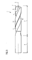
- FIG. 3 shows an overall view of the tool bar 1, FIG. 4 a cross section through the tool bar 1 in Spansch Scheme, FIG. 5 a design of the drill bit of the tool bar 1, FIG. 6 an enlarged view of the chip chamber area of the tool bar of FIG. 3 and FIG. 7 a section of FIG. 6 ,
- the tool bar 1 has a longitudinal axis 3. Spaced from the longitudinal axis 3 extends at least one chip chamber 4. According to the FIGS. 3 to 7 There are two chip chambers 4, which are diametrically opposite each other with respect to the longitudinal axis 3. Neither the number of chip chambers 4 nor their arrangement with respect to the longitudinal axis 3, however, is mandatory. The decisive factor is that at least one chip chamber 4 is present. Furthermore, as a rule the chip chambers 4 are the same. However, this is not necessary.
- the chip chambers 4 extend spirally around the longitudinal axis 3. However, this is not mandatory.
- the chip chambers 4 could alternatively have only a slight twist or run completely parallel to the longitudinal axis 3.
- the decisive factor is that they are spaced from the longitudinal axis 3 and extend along the longitudinal axis 3.
- the chip chambers 4 do not extend over the entire length of the tool rod 1.
- the region over which the chip chambers 4 extend in the direction of the longitudinal axis 3 forms a chip chamber region 5, the remaining region of the tool rod 1 a shaft 6.
- the tool bar 1 Due to the design of the tool bar 1 of FIGS. 3 to 7 as a drill, the tool bar 1 has a drill tip 7.
- the drill tip 7 is designed conical in the rule.
- main cutting edges 8 (main cutting edges 8) are introduced into the tool bar.
- the main cutting edges 8 adjoin the end faces of the chip chambers 4.
- the introduction of the main cutting edges 8 in the tool bar 1 takes place in the same manner as in the prior art.
- the chip chambers 4 are ground at the drill tip 7 only as far as required for introducing the main cutting edges 8.
- the not adjacent to the main cutting edges 8 part of the chip chambers 4 is not ground on the drill bit 7.
- the chip chambers 4 are ground in the region of the drill tip 7 parallel to the longitudinal axis 3 a piece 9 ground.
- the length of this piece 9 is preferably between half and twice the diameter of the tool bar 1.
- the length of the piece 9 may be between 0.8 times and 1.2 times the diameter of the tool bar 1.
- additional cutting edges 10 are introduced into the tool bar 1, which also adjoin the chip chambers 4. Also, the introduction of the additional cutting edges 10 takes place - as in the prior art - in the already sintered tool rod 1. In contrast to the prior art, however, the chip chamber region 4 is also partially unground at the additional cutting edges 10. In particular, according to the FIGS. 3 to 7 the grinding of the chip chambers 4 only in the immediate vicinity of the additional cutting edges 10. The remaining area of the chip chambers 4 remains unground. Except in the vicinity of the drill tip 7 (keyword: piece 9), the chip chambers 4 are therefore ground exclusively in the area of the additional cutting edges 10.
- the additional cutting edges 10 are limited by two interfaces 11, 12.
- the boundary surfaces 11 at the same time limit the chip chambers 4.
- the boundary surfaces 12 do not delimit the chip chambers 4.
- the interfaces 12 may alternatively be ground or at least partially unpolished.
- the boundary surfaces 12 need only be ground in the area of the additional cutting edges 10 (and in the region of the drill tip 7).
- the diameter in the region of the boundary surfaces 12 may, for example, be between 0.9 and 0.95 times the nominal diameter.
- the present invention is not limited to tool bars 1, which are formed as a drill.
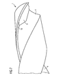
- the tool bar 1 may be formed, for example, as a milling head. This will be described below in connection with the FIGS. 8, 9 and 10 briefly explained.
- the milling head 1 also has the shank 6 and the chip chamber area 5.
- chip chambers 4 are introduced into the tool bar.
- the main cutting edges 8 continue to adjoin the chip chambers 4, but, like the chip chambers 4, for example, extend in a spiral around the longitudinal axis 3.
- the chip chambers 4 are - similar to the design of the tool bar 1 as a drill - only partially ground and otherwise unground.
- FIG. 8 has a substantially cylindrical contour
- an end face 13 of the milling head 1 must also be ground in the rule.
- the milling head 1 is curved inwardly at its end faces 13. In this case, it is also possible to grind the end faces 13 only in the area of the main cutting edges 8 and, moreover, to leave them unpolished.
Landscapes
- Engineering & Computer Science (AREA)
- Mechanical Engineering (AREA)
- Drilling Tools (AREA)
- Powder Metallurgy (AREA)
Claims (12)
- Procédé de fabrication pour une tige d'outil (1) composée d'un matériau fritté, comprenant les étapes suivantes, exécutées dans l'ordre indiqué :- fabriquer une ébauche ayant un axe longitudinal (3), à partir du matériau à fritter,- introduire dans l'ébauche au moins un logement de copeaux (4) s'étendant suivant l'axe longitudinal (3) en étant espacé de l'axe longitudinal (3),- fabriquer la tige d'outil (1) par frittage de l'ébauche,- introduire par rectification dans la tige d'outil (1) au moins une arête de coupe (8, 10) adjacente au logement de copeaux (4) et continuer à usiner la tige d'outil (1) par rectification, dans lequel le logement de copeaux (4) est toutefois rectifié uniquement dans une zone (9) adjacente à au moins l'une des arêtes de coupe (8, 10) et reste par ailleurs non rectifié.
- Procédé de fabrication selon la revendication 1, caractérisé en ce qu'au moins l'une (8) des arêtes de coupe (8, 10) s'étend sur la face frontale de la tige d'outil (1), et en ce que le logement de copeaux (4), dans la mesure où il est adjacent à cette arête de coupe (8), est rectifié, vu dans la direction de l'axe longitudinal (3), sur une longueur comprise entre la moitié et le double du diamètre de la tige d'outil (1), en particulier entre 0,8 fois et 1,2 fois le diamètre de la tige d'outil (1).
- Procédé de fabrication selon la revendication 2, caractérisé en ce que la tige d'outil (1) est réalisée comme un foret, et en ce que l'arête de coupe (8) frontale est disposée au niveau de la mèche (7).
- Procédé de fabrication selon la revendication 1, 2 ou 3, caractérisé en ce qu'au moins l'une des arêtes de coupe (8, 10) s'étend suivant l'axe longitudinal (3) de la tige d'outil (1), et en ce que le logement de copeaux (4), dans la mesure où il est adjacent à cette arête de coupe (8), est rectifié uniquement dans une zone directement adjacente à cette arête de coupe (8, 10).
- Procédé de fabrication selon la revendication 4, caractérisé en ce que l'arête de coupe (8, 10) s'étendant suivant l'axe longitudinal (3) de la tige d'outil (1) est délimitée par deux surfaces limites (11, 12), en ce que l'une surface limite (11) délimite en même temps le logement de copeaux (4) et l'autre surface limite (12) ne délimite pas le logement de copeaux (4), et en ce que l'autre surface limite (12) n'est pas rectifiée, au moins en partie.
- Tige d'outil prête à l'emploi, composée d'un matériau fritté,- dans laquelle la tige d'outil présente un axe longitudinal (3), et dans la tige d'outil est introduit au moins un logement de copeaux (4) s'étendant suivant l'axe longitudinal (3) en étant espacé de l'axe longitudinal (3),- dans laquelle la tige d'outil présente au moins une arête de coupe (8, 10) adjacente au logement de copeaux (4) et introduite dans la tige d'outil par rectification de la tige d'outil déjà frittée,caractérisée en ce que le logement de copeaux (4) est rectifié uniquement dans une zone (9) adjacente à au moins l'une des arêtes de coupe (8, 10) et par ailleurs non rectifié.
- Tige d'outil selon la revendication 6, caractérisée en ce qu'au moins l'une (8) des arêtes de coupe (8, 10) s'étend sur la face frontale de la tige d'outil, et en ce que le logement de copeaux (4), dans la mesure où il est adjacent à cette arête de coupe (8), est rectifié, vu dans la direction de l'axe longitudinal (3), sur une longueur comprise entre la moitié et le double du diamètre de la tige d'outil, en particulier entre 0,8 fois et 1,2 fois le diamètre de la tige d'outil.
- Tige d'outil selon la revendication 7, caractérisée en ce que la tige d'outil est réalisée comme un foret, et en ce que l'arête de coupe (8) frontale est disposée au niveau de la mèche (7).
- Tige d'outil selon la revendication 6, 7 ou 8, caractérisée en ce qu'au moins l'une des arêtes de coupe (8, 10) s'étend suivant l'axe longitudinal (3) de la tige d'outil, et en ce que le logement de copeaux (4), dans la mesure où il est adjacent à cette arête de coupe (8), est rectifié uniquement dans une zone directement adjacente à cette arête de coupe (8, 10).
- Tige d'outil selon la revendication 9, caractérisée en ce que l'arête de coupe (8, 10) s'étendant suivant l'axe longitudinal (3) de la tige d'outil est délimitée par deux surfaces limites (11, 12), en ce que l'une surface limite (11) délimite en même temps le logement de copeaux (4) et l'autre surface limite (12) ne délimite pas le logement de copeaux (4), et en ce que l'autre surface limite (12) n'est pas rectifiée, au moins en partie.
- Tige d'outil selon l'une quelconque des revendications 6 à 10, caractérisée en ce que le matériau est un métal ou un mélange métal/céramique.
- Utilisation d'une tige d'outil (1) selon l'une quelconque des revendications 6 à 11 pour l'usinage par enlèvement de copeaux d'une pièce à travailler (2).
Applications Claiming Priority (2)
| Application Number | Priority Date | Filing Date | Title |
|---|---|---|---|
| DE102007044269A DE102007044269A1 (de) | 2007-09-17 | 2007-09-17 | Nur teilweise geschliffener Werkzeugstab aus Sintermaterial |
| PCT/EP2008/062236 WO2009037223A1 (fr) | 2007-09-17 | 2008-09-15 | Tige d'outil en matériau fritté seulement partiellement affûtée |
Publications (2)
| Publication Number | Publication Date |
|---|---|
| EP2200773A1 EP2200773A1 (fr) | 2010-06-30 |
| EP2200773B1 true EP2200773B1 (fr) | 2013-07-24 |
Family
ID=40223762
Family Applications (1)
| Application Number | Title | Priority Date | Filing Date |
|---|---|---|---|
| EP08804197.5A Active EP2200773B1 (fr) | 2007-09-17 | 2008-09-15 | Tige d'outil en matériau fritté seulement partiellement affûtée |
Country Status (6)
| Country | Link |
|---|---|
| US (1) | US8740517B2 (fr) |
| EP (1) | EP2200773B1 (fr) |
| JP (1) | JP5306351B2 (fr) |
| CN (1) | CN101801574B (fr) |
| DE (1) | DE102007044269A1 (fr) |
| WO (1) | WO2009037223A1 (fr) |
Families Citing this family (9)
| Publication number | Priority date | Publication date | Assignee | Title |
|---|---|---|---|---|
| DE102010017163A1 (de) * | 2010-05-31 | 2011-12-01 | Gühring Ohg | Bohrwerkzeug |
| EP2502710B1 (fr) | 2011-03-22 | 2020-04-22 | Black & Decker Inc. | Ciseaux |
| US9656331B2 (en) * | 2011-11-15 | 2017-05-23 | Kennametal Inc. | System and method for simultaneously forming flutes in solid carbide tools |
| DE102013004105A1 (de) * | 2013-03-11 | 2014-09-11 | Audi Ag | Bohrwerkzeug, insbesondere Reibahle |
| USD737875S1 (en) * | 2013-03-15 | 2015-09-01 | Black & Decker Inc. | Drill bit |
| USD734792S1 (en) * | 2013-03-15 | 2015-07-21 | Black & Decker Inc. | Drill bit |
| US9333564B2 (en) | 2013-03-15 | 2016-05-10 | Black & Decker Inc. | Drill bit |
| USD734790S1 (en) * | 2013-06-12 | 2015-07-21 | Element Six (Production) (Pty) Ltd | Drill bit tip |
| CN104942556A (zh) * | 2015-06-15 | 2015-09-30 | 广西宜州玉柴农业装备有限公司 | 旋耕机旋刀的加工方法 |
Family Cites Families (26)
| Publication number | Priority date | Publication date | Assignee | Title |
|---|---|---|---|---|
| DE1804222A1 (de) * | 1968-02-06 | 1969-08-14 | Ford Werke Ag | Verfahren zur Herstellung eines Bohrers |
| US3824026A (en) * | 1973-03-19 | 1974-07-16 | T Gaskins | Cutting lead tips for drill bits |
| JPS6039408A (ja) | 1983-08-09 | 1985-03-01 | Nikkiso Co Ltd | 炭素繊維用前駆体繊維の製造方法 |
| JPS6039408U (ja) * | 1983-08-24 | 1985-03-19 | 三菱マテリアル株式会社 | 一部非研削超硬ドリル |
| DE3601385A1 (de) * | 1986-01-18 | 1987-07-23 | Krupp Gmbh | Verfahren zur herstellung von sinterkoerpern mit inneren kanaelen, strangpresswerkzeug zur durchfuehrung des verfahrens und bohrwerkzeug |
| DE3636798A1 (de) * | 1986-10-29 | 1988-04-07 | Krupp Gmbh | Verfahren zur herstellung von einteiligen gesinterten schneidwerkzeugen in schaftausfuehrung |
| DE3853518T3 (de) * | 1987-12-14 | 2004-06-03 | Mitsubishi Materials Corp. | Spiralbohrer. |
| JPH0442311A (ja) | 1990-06-08 | 1992-02-12 | Nippon Chemicon Corp | 組物試験片の汎用支持装置 |
| JP2533255Y2 (ja) * | 1990-08-10 | 1997-04-23 | 本田技研工業株式会社 | ドリル |
| DE4301261A1 (de) * | 1993-01-19 | 1994-07-21 | Emhart Inc | Bohrwerkzeug nach Art eines Spiralbohrers |
| DE9313618U1 (de) * | 1993-09-09 | 1993-11-11 | Wilhelm Fette Gmbh, 21493 Schwarzenbek | Wälzfräser |
| DE9417778U1 (de) * | 1994-11-05 | 1994-12-15 | wolfcraft GmbH, 56745 Weibern | Forstner-Bohrer |
| US5716170A (en) * | 1996-05-15 | 1998-02-10 | Kennametal Inc. | Diamond coated cutting member and method of making the same |
| US5701578A (en) * | 1996-11-20 | 1997-12-23 | Kennametal Inc. | Method for making a diamond-coated member |
| DE19648971A1 (de) * | 1996-11-26 | 1998-05-28 | Drebo Werkzeugfab Gmbh | Bohrer sowie Verfahren zu seiner Herstellung |
| DE19910580C1 (de) * | 1999-03-10 | 2000-07-27 | Tigra Hartstoff Gmbh | Schaftfräserrohling aus Hartwerkstoff |
| DE19955172A1 (de) * | 1999-11-16 | 2001-05-23 | Kennametal Inc | Verfahren zum Schleifen einer Bohrspitze und Bohrerspitze |
| PL193572B1 (pl) * | 2000-03-10 | 2007-02-28 | American Tool Companies As | Wiertło |
| DE10142265B4 (de) | 2001-08-29 | 2005-04-28 | Arno Friedrichs | Stabförmiges Werkzeug zur spanenden Bearbeitung eines Werkstücks |
| JP3985713B2 (ja) * | 2003-03-31 | 2007-10-03 | 三菱マテリアル株式会社 | ドリル |
| DE20307258U1 (de) * | 2003-05-09 | 2004-09-16 | Gühring, Jörg, Dr. | Bohrwerkzeug zur Zerspanung von Guss-Werkstoffen |
| JP2005022064A (ja) * | 2003-07-03 | 2005-01-27 | Tungaloy Corp | 被覆穴あけ工具 |
| SE527456C2 (sv) * | 2003-07-28 | 2006-03-14 | Sandvik Intellectual Property | Förfarande och anordning för tillverkning genom extrusion av roterande verktyg för spånavskiljande bearbetning och verktyg |
| CN2820394Y (zh) * | 2005-09-14 | 2006-09-27 | 江苏天工工具股份有限公司 | 一种分屑强力钻 |
| US7478977B2 (en) * | 2005-10-18 | 2009-01-20 | Osg Corporation | Ball endmill |
| US20080019787A1 (en) * | 2006-07-24 | 2008-01-24 | Karthikeyan Sampath | Drill for machining fiber reinforced composite material |
-
2007
- 2007-09-17 DE DE102007044269A patent/DE102007044269A1/de not_active Withdrawn
-
2008
- 2008-09-15 JP JP2010525313A patent/JP5306351B2/ja active Active
- 2008-09-15 CN CN2008801064732A patent/CN101801574B/zh active Active
- 2008-09-15 US US12/733,683 patent/US8740517B2/en active Active
- 2008-09-15 EP EP08804197.5A patent/EP2200773B1/fr active Active
- 2008-09-15 WO PCT/EP2008/062236 patent/WO2009037223A1/fr active Application Filing
Also Published As
| Publication number | Publication date |
|---|---|
| CN101801574B (zh) | 2011-10-12 |
| JP5306351B2 (ja) | 2013-10-02 |
| DE102007044269A1 (de) | 2009-03-19 |
| WO2009037223A1 (fr) | 2009-03-26 |
| EP2200773A1 (fr) | 2010-06-30 |
| US20100232898A1 (en) | 2010-09-16 |
| CN101801574A (zh) | 2010-08-11 |
| US8740517B2 (en) | 2014-06-03 |
| JP2010538856A (ja) | 2010-12-16 |
Similar Documents
| Publication | Publication Date | Title |
|---|---|---|
| EP2200773B1 (fr) | Tige d'outil en matériau fritté seulement partiellement affûtée | |
| DE102009030689B4 (de) | Mehrschneidiges Bohrwerkzeug | |
| EP0118035B1 (fr) | Outil de forage et procédé pour sa fabrication | |
| DE102010006796B4 (de) | Verfahren zur Herstellung eines Bohrers, sowie Bohrer | |
| DE102014108219A1 (de) | Rotationswerkzeug sowie Verfahren zur Herstellung eines Rotationswerkzeugs | |
| DE102012001796A1 (de) | Segmentierter Orbitalbohrer | |
| WO2016020047A1 (fr) | Outil de fraisage | |
| DE19806864A1 (de) | Reibwerkzeug und Verfahren zu dessen Herstellung | |
| EP3150316B1 (fr) | Fraise à queue | |
| EP2670550B1 (fr) | Outil de forage et procede de fabrication de trous | |
| DE112011102667T5 (de) | Konturschaftfräser | |
| DE102019102726A1 (de) | Bohrwerkzeug und Verfahren zur Erzeugung einer Bohrung | |
| DE102010018339A1 (de) | Feinbearbeitungswerkzeug | |
| EP2848342B1 (fr) | Outil de fraisage complet pour l'usinage rotatif de matériaux | |
| DE102009043850A1 (de) | Werkzeug | |
| WO2010034410A1 (fr) | Outil d'usinage par enlèvement de copeaux | |
| DE10142265A1 (de) | Stabförmiges Werkzeug zur spanenden Bearbeitung eines Werkstücks | |
| WO2014195009A1 (fr) | Outil d'usinage par enlèvement de copeaux et procédé de production d'un outil d'usinage par enlèvement de copeaux | |
| DE102018119927A1 (de) | Faswerkzeug | |
| WO2008080748A1 (fr) | Foret de forage de trous profonds doté d'une bague de soutien et procédé pour sa fabrication | |
| AT16076U1 (de) | Werkzeugkörper sowie ein Verfahren zur Herstellung | |
| DE10318948A1 (de) | Kombinationswerkzeug | |
| DE3636798A1 (de) | Verfahren zur herstellung von einteiligen gesinterten schneidwerkzeugen in schaftausfuehrung | |
| AT16369U1 (de) | Verfahren zur Herstellung eines sintergefügten Verbundkörpers | |
| DE102017212053A1 (de) | Rotationswerkzeug sowie Verfahren zur Herstellung eines Rotationswerkzeugs |
Legal Events
| Date | Code | Title | Description |
|---|---|---|---|
| PUAI | Public reference made under article 153(3) epc to a published international application that has entered the european phase |
Free format text: ORIGINAL CODE: 0009012 |
|
| 17P | Request for examination filed |
Effective date: 20100419 |
|
| AK | Designated contracting states |
Kind code of ref document: A1 Designated state(s): AT BE BG CH CY CZ DE DK EE ES FI FR GB GR HR HU IE IS IT LI LT LU LV MC MT NL NO PL PT RO SE SI SK TR |
|
| AX | Request for extension of the european patent |
Extension state: AL BA MK RS |
|
| DAX | Request for extension of the european patent (deleted) | ||
| GRAP | Despatch of communication of intention to grant a patent |
Free format text: ORIGINAL CODE: EPIDOSNIGR1 |
|
| INTG | Intention to grant announced |
Effective date: 20130429 |
|
| GRAS | Grant fee paid |
Free format text: ORIGINAL CODE: EPIDOSNIGR3 |
|
| GRAA | (expected) grant |
Free format text: ORIGINAL CODE: 0009210 |
|
| AK | Designated contracting states |
Kind code of ref document: B1 Designated state(s): AT BE BG CH CY CZ DE DK EE ES FI FR GB GR HR HU IE IS IT LI LT LU LV MC MT NL NO PL PT RO SE SI SK TR |
|
| REG | Reference to a national code |
Ref country code: GB Ref legal event code: FG4D Free format text: NOT ENGLISH |
|
| REG | Reference to a national code |
Ref country code: CH Ref legal event code: EP |
|
| REG | Reference to a national code |
Ref country code: AT Ref legal event code: REF Ref document number: 623102 Country of ref document: AT Kind code of ref document: T Effective date: 20130815 |
|
| REG | Reference to a national code |
Ref country code: IE Ref legal event code: FG4D Free format text: LANGUAGE OF EP DOCUMENT: GERMAN |
|
| REG | Reference to a national code |
Ref country code: CH Ref legal event code: NV Representative=s name: KELLER AND PARTNER PATENTANWAELTE AG, CH |
|
| REG | Reference to a national code |
Ref country code: DE Ref legal event code: R096 Ref document number: 502008010375 Country of ref document: DE Effective date: 20130919 |
|
| REG | Reference to a national code |
Ref country code: SE Ref legal event code: TRGR |
|
| REG | Reference to a national code |
Ref country code: NL Ref legal event code: VDEP Effective date: 20130724 |
|
| REG | Reference to a national code |
Ref country code: LT Ref legal event code: MG4D |
|
| PG25 | Lapsed in a contracting state [announced via postgrant information from national office to epo] |
Ref country code: LT Free format text: LAPSE BECAUSE OF FAILURE TO SUBMIT A TRANSLATION OF THE DESCRIPTION OR TO PAY THE FEE WITHIN THE PRESCRIBED TIME-LIMIT Effective date: 20130724 Ref country code: PT Free format text: LAPSE BECAUSE OF FAILURE TO SUBMIT A TRANSLATION OF THE DESCRIPTION OR TO PAY THE FEE WITHIN THE PRESCRIBED TIME-LIMIT Effective date: 20131125 Ref country code: NO Free format text: LAPSE BECAUSE OF FAILURE TO SUBMIT A TRANSLATION OF THE DESCRIPTION OR TO PAY THE FEE WITHIN THE PRESCRIBED TIME-LIMIT Effective date: 20131024 Ref country code: HR Free format text: LAPSE BECAUSE OF FAILURE TO SUBMIT A TRANSLATION OF THE DESCRIPTION OR TO PAY THE FEE WITHIN THE PRESCRIBED TIME-LIMIT Effective date: 20130724 Ref country code: CY Free format text: LAPSE BECAUSE OF FAILURE TO SUBMIT A TRANSLATION OF THE DESCRIPTION OR TO PAY THE FEE WITHIN THE PRESCRIBED TIME-LIMIT Effective date: 20130828 Ref country code: IS Free format text: LAPSE BECAUSE OF FAILURE TO SUBMIT A TRANSLATION OF THE DESCRIPTION OR TO PAY THE FEE WITHIN THE PRESCRIBED TIME-LIMIT Effective date: 20131124 |
|
| PG25 | Lapsed in a contracting state [announced via postgrant information from national office to epo] |
Ref country code: PL Free format text: LAPSE BECAUSE OF FAILURE TO SUBMIT A TRANSLATION OF THE DESCRIPTION OR TO PAY THE FEE WITHIN THE PRESCRIBED TIME-LIMIT Effective date: 20130724 Ref country code: FI Free format text: LAPSE BECAUSE OF FAILURE TO SUBMIT A TRANSLATION OF THE DESCRIPTION OR TO PAY THE FEE WITHIN THE PRESCRIBED TIME-LIMIT Effective date: 20130724 Ref country code: LV Free format text: LAPSE BECAUSE OF FAILURE TO SUBMIT A TRANSLATION OF THE DESCRIPTION OR TO PAY THE FEE WITHIN THE PRESCRIBED TIME-LIMIT Effective date: 20130724 Ref country code: GR Free format text: LAPSE BECAUSE OF FAILURE TO SUBMIT A TRANSLATION OF THE DESCRIPTION OR TO PAY THE FEE WITHIN THE PRESCRIBED TIME-LIMIT Effective date: 20131025 Ref country code: SI Free format text: LAPSE BECAUSE OF FAILURE TO SUBMIT A TRANSLATION OF THE DESCRIPTION OR TO PAY THE FEE WITHIN THE PRESCRIBED TIME-LIMIT Effective date: 20130724 Ref country code: NL Free format text: LAPSE BECAUSE OF FAILURE TO SUBMIT A TRANSLATION OF THE DESCRIPTION OR TO PAY THE FEE WITHIN THE PRESCRIBED TIME-LIMIT Effective date: 20130724 |
|
| BERE | Be: lapsed |
Owner name: FRIEDRICHS, ARNO Effective date: 20130930 |
|
| PG25 | Lapsed in a contracting state [announced via postgrant information from national office to epo] |
Ref country code: CY Free format text: LAPSE BECAUSE OF FAILURE TO SUBMIT A TRANSLATION OF THE DESCRIPTION OR TO PAY THE FEE WITHIN THE PRESCRIBED TIME-LIMIT Effective date: 20130724 |
|
| PG25 | Lapsed in a contracting state [announced via postgrant information from national office to epo] |
Ref country code: MC Free format text: LAPSE BECAUSE OF FAILURE TO SUBMIT A TRANSLATION OF THE DESCRIPTION OR TO PAY THE FEE WITHIN THE PRESCRIBED TIME-LIMIT Effective date: 20130724 Ref country code: RO Free format text: LAPSE BECAUSE OF FAILURE TO SUBMIT A TRANSLATION OF THE DESCRIPTION OR TO PAY THE FEE WITHIN THE PRESCRIBED TIME-LIMIT Effective date: 20130724 Ref country code: DK Free format text: LAPSE BECAUSE OF FAILURE TO SUBMIT A TRANSLATION OF THE DESCRIPTION OR TO PAY THE FEE WITHIN THE PRESCRIBED TIME-LIMIT Effective date: 20130724 Ref country code: SK Free format text: LAPSE BECAUSE OF FAILURE TO SUBMIT A TRANSLATION OF THE DESCRIPTION OR TO PAY THE FEE WITHIN THE PRESCRIBED TIME-LIMIT Effective date: 20130724 Ref country code: CZ Free format text: LAPSE BECAUSE OF FAILURE TO SUBMIT A TRANSLATION OF THE DESCRIPTION OR TO PAY THE FEE WITHIN THE PRESCRIBED TIME-LIMIT Effective date: 20130724 Ref country code: EE Free format text: LAPSE BECAUSE OF FAILURE TO SUBMIT A TRANSLATION OF THE DESCRIPTION OR TO PAY THE FEE WITHIN THE PRESCRIBED TIME-LIMIT Effective date: 20130724 |
|
| PG25 | Lapsed in a contracting state [announced via postgrant information from national office to epo] |
Ref country code: ES Free format text: LAPSE BECAUSE OF FAILURE TO SUBMIT A TRANSLATION OF THE DESCRIPTION OR TO PAY THE FEE WITHIN THE PRESCRIBED TIME-LIMIT Effective date: 20130724 |
|
| PLBE | No opposition filed within time limit |
Free format text: ORIGINAL CODE: 0009261 |
|
| STAA | Information on the status of an ep patent application or granted ep patent |
Free format text: STATUS: NO OPPOSITION FILED WITHIN TIME LIMIT |
|
| 26N | No opposition filed |
Effective date: 20140425 |
|
| REG | Reference to a national code |
Ref country code: IE Ref legal event code: MM4A |
|
| PG25 | Lapsed in a contracting state [announced via postgrant information from national office to epo] |
Ref country code: IE Free format text: LAPSE BECAUSE OF NON-PAYMENT OF DUE FEES Effective date: 20130915 Ref country code: BE Free format text: LAPSE BECAUSE OF NON-PAYMENT OF DUE FEES Effective date: 20130930 |
|
| REG | Reference to a national code |
Ref country code: DE Ref legal event code: R097 Ref document number: 502008010375 Country of ref document: DE Effective date: 20140425 |
|
| REG | Reference to a national code |
Ref country code: DE Ref legal event code: R082 Ref document number: 502008010375 Country of ref document: DE Representative=s name: ZIMMERMANN & PARTNER, DE Ref country code: DE Ref legal event code: R082 Ref document number: 502008010375 Country of ref document: DE Representative=s name: ZIMMERMANN & PARTNER PATENTANWAELTE MBB, DE |
|
| REG | Reference to a national code |
Ref country code: CH Ref legal event code: PCAR Free format text: NEW ADDRESS: EIGERSTRASSE 2 POSTFACH, 3000 BERN 14 (CH) |
|
| PG25 | Lapsed in a contracting state [announced via postgrant information from national office to epo] |
Ref country code: TR Free format text: LAPSE BECAUSE OF FAILURE TO SUBMIT A TRANSLATION OF THE DESCRIPTION OR TO PAY THE FEE WITHIN THE PRESCRIBED TIME-LIMIT Effective date: 20130724 Ref country code: MT Free format text: LAPSE BECAUSE OF FAILURE TO SUBMIT A TRANSLATION OF THE DESCRIPTION OR TO PAY THE FEE WITHIN THE PRESCRIBED TIME-LIMIT Effective date: 20130724 |
|
| PG25 | Lapsed in a contracting state [announced via postgrant information from national office to epo] |
Ref country code: BG Free format text: LAPSE BECAUSE OF FAILURE TO SUBMIT A TRANSLATION OF THE DESCRIPTION OR TO PAY THE FEE WITHIN THE PRESCRIBED TIME-LIMIT Effective date: 20130724 Ref country code: HU Free format text: LAPSE BECAUSE OF FAILURE TO SUBMIT A TRANSLATION OF THE DESCRIPTION OR TO PAY THE FEE WITHIN THE PRESCRIBED TIME-LIMIT; INVALID AB INITIO Effective date: 20080915 |
|
| REG | Reference to a national code |
Ref country code: FR Ref legal event code: PLFP Year of fee payment: 8 |
|
| REG | Reference to a national code |
Ref country code: FR Ref legal event code: PLFP Year of fee payment: 9 |
|
| REG | Reference to a national code |
Ref country code: FR Ref legal event code: PLFP Year of fee payment: 10 |
|
| REG | Reference to a national code |
Ref country code: FR Ref legal event code: PLFP Year of fee payment: 11 |
|
| REG | Reference to a national code |
Ref country code: DE Ref legal event code: R082 Ref document number: 502008010375 Country of ref document: DE Representative=s name: ZIMMERMANN & PARTNER PATENTANWAELTE MBB, DE Ref country code: DE Ref legal event code: R081 Ref document number: 502008010375 Country of ref document: DE Owner name: ARNO FRIEDRICHS HARTMETALL GMBH & CO. KG, DE Free format text: FORMER OWNER: FRIEDRICHS, ARNO, 95326 KULMBACH, DE |
|
| REG | Reference to a national code |
Ref country code: CH Ref legal event code: PUE Owner name: ARNO FRIEDRICHS HARTMETALL GMBH AND CO. KG, DE Free format text: FORMER OWNER: FRIEDRICHS, ARNO, DE |
|
| REG | Reference to a national code |
Ref country code: LU Ref legal event code: PD Owner name: ARNO FRIEDRICHS HARTMETALL GMBH & CO. KG; DE Free format text: FORMER OWNER: FRIEDRICHS ARNO Effective date: 20191203 |
|
| REG | Reference to a national code |
Ref country code: GB Ref legal event code: 732E Free format text: REGISTERED BETWEEN 20200102 AND 20200108 |
|
| REG | Reference to a national code |
Ref country code: AT Ref legal event code: PC Ref document number: 623102 Country of ref document: AT Kind code of ref document: T Owner name: ARNO FRIEDRICHS HARTMETALL GMBH & CO. KG, DE Effective date: 20200312 |
|
| REG | Reference to a national code |
Ref country code: CH Ref legal event code: PFA Owner name: ARNO FRIEDRICHS HARTMETALL GMBH AND CO. KG, DE Free format text: FORMER OWNER: ARNO FRIEDRICHS HARTMETALL GMBH AND CO. KG, DE |
|
| P01 | Opt-out of the competence of the unified patent court (upc) registered |
Effective date: 20230703 |
|
| PGFP | Annual fee paid to national office [announced via postgrant information from national office to epo] |
Ref country code: LU Payment date: 20230927 Year of fee payment: 16 Ref country code: IT Payment date: 20230921 Year of fee payment: 16 Ref country code: GB Payment date: 20230927 Year of fee payment: 16 Ref country code: AT Payment date: 20230821 Year of fee payment: 16 |
|
| PGFP | Annual fee paid to national office [announced via postgrant information from national office to epo] |
Ref country code: SE Payment date: 20230927 Year of fee payment: 16 Ref country code: FR Payment date: 20230925 Year of fee payment: 16 |
|
| PGFP | Annual fee paid to national office [announced via postgrant information from national office to epo] |
Ref country code: CH Payment date: 20231004 Year of fee payment: 16 |
|
| PGFP | Annual fee paid to national office [announced via postgrant information from national office to epo] |
Ref country code: DE Payment date: 20240927 Year of fee payment: 17 |