EP2200523B1 - Système de mélange et d'administration de ciment osseux et ses procédés d'utilisation - Google Patents
Système de mélange et d'administration de ciment osseux et ses procédés d'utilisation Download PDFInfo
- Publication number
- EP2200523B1 EP2200523B1 EP08829040.8A EP08829040A EP2200523B1 EP 2200523 B1 EP2200523 B1 EP 2200523B1 EP 08829040 A EP08829040 A EP 08829040A EP 2200523 B1 EP2200523 B1 EP 2200523B1
- Authority
- EP
- European Patent Office
- Prior art keywords
- powder
- tube
- tubes
- bone cement
- gas
- Prior art date
- Legal status (The legal status is an assumption and is not a legal conclusion. Google has not performed a legal analysis and makes no representation as to the accuracy of the status listed.)
- Active
Links
- 238000002156 mixing Methods 0.000 title claims description 43
- 239000002639 bone cement Substances 0.000 title claims description 22
- 238000000034 method Methods 0.000 title claims description 15
- 239000000843 powder Substances 0.000 claims description 68
- 239000001506 calcium phosphate Substances 0.000 claims description 43
- QORWJWZARLRLPR-UHFFFAOYSA-H tricalcium bis(phosphate) Chemical compound [Ca+2].[Ca+2].[Ca+2].[O-]P([O-])([O-])=O.[O-]P([O-])([O-])=O QORWJWZARLRLPR-UHFFFAOYSA-H 0.000 claims description 41
- 229910000389 calcium phosphate Inorganic materials 0.000 claims description 39
- 235000011010 calcium phosphates Nutrition 0.000 claims description 39
- 239000007788 liquid Substances 0.000 claims description 25
- FAPWRFPIFSIZLT-UHFFFAOYSA-M Sodium chloride Chemical compound [Na+].[Cl-] FAPWRFPIFSIZLT-UHFFFAOYSA-M 0.000 claims description 12
- 239000012530 fluid Substances 0.000 claims description 12
- 239000011780 sodium chloride Substances 0.000 claims description 12
- 238000013022 venting Methods 0.000 claims description 10
- 230000004888 barrier function Effects 0.000 claims description 9
- 230000000881 depressing effect Effects 0.000 claims description 8
- 238000004891 communication Methods 0.000 claims description 5
- 238000004806 packaging method and process Methods 0.000 claims description 4
- XLYOFNOQVPJJNP-UHFFFAOYSA-N water Substances O XLYOFNOQVPJJNP-UHFFFAOYSA-N 0.000 claims description 4
- 239000013060 biological fluid Substances 0.000 claims description 3
- 238000005304 joining Methods 0.000 claims description 3
- 239000008363 phosphate buffer Substances 0.000 claims description 3
- 159000000007 calcium salts Chemical class 0.000 claims 1
- 239000000203 mixture Substances 0.000 description 28
- 239000000463 material Substances 0.000 description 27
- 239000004568 cement Substances 0.000 description 15
- 210000002381 plasma Anatomy 0.000 description 8
- 210000004369 blood Anatomy 0.000 description 7
- 239000008280 blood Substances 0.000 description 7
- 239000011575 calcium Substances 0.000 description 7
- 239000007789 gas Substances 0.000 description 6
- 238000012546 transfer Methods 0.000 description 6
- 210000000988 bone and bone Anatomy 0.000 description 5
- 239000000306 component Substances 0.000 description 5
- 239000002274 desiccant Substances 0.000 description 5
- FUFJGUQYACFECW-UHFFFAOYSA-L calcium hydrogenphosphate Chemical compound [Ca+2].OP([O-])([O-])=O FUFJGUQYACFECW-UHFFFAOYSA-L 0.000 description 4
- RBLGLDWTCZMLRW-UHFFFAOYSA-K dicalcium phosphate dihydrate Substances O.O.[Ca+2].[Ca+2].[O-]P([O-])([O-])=O RBLGLDWTCZMLRW-UHFFFAOYSA-K 0.000 description 4
- 229910052588 hydroxylapatite Inorganic materials 0.000 description 4
- XYJRXVWERLGGKC-UHFFFAOYSA-D pentacalcium;hydroxide;triphosphate Chemical compound [OH-].[Ca+2].[Ca+2].[Ca+2].[Ca+2].[Ca+2].[O-]P([O-])([O-])=O.[O-]P([O-])([O-])=O.[O-]P([O-])([O-])=O XYJRXVWERLGGKC-UHFFFAOYSA-D 0.000 description 4
- LYCAIKOWRPUZTN-UHFFFAOYSA-N Ethylene glycol Chemical compound OCCO LYCAIKOWRPUZTN-UHFFFAOYSA-N 0.000 description 3
- 239000013543 active substance Substances 0.000 description 3
- 229910052586 apatite Inorganic materials 0.000 description 3
- 239000003795 chemical substances by application Substances 0.000 description 3
- 238000011109 contamination Methods 0.000 description 3
- VSIIXMUUUJUKCM-UHFFFAOYSA-D pentacalcium;fluoride;triphosphate Chemical compound [F-].[Ca+2].[Ca+2].[Ca+2].[Ca+2].[Ca+2].[O-]P([O-])([O-])=O.[O-]P([O-])([O-])=O.[O-]P([O-])([O-])=O VSIIXMUUUJUKCM-UHFFFAOYSA-D 0.000 description 3
- -1 polypropylene Polymers 0.000 description 3
- 238000002360 preparation method Methods 0.000 description 3
- XKRFYHLGVUSROY-UHFFFAOYSA-N Argon Chemical compound [Ar] XKRFYHLGVUSROY-UHFFFAOYSA-N 0.000 description 2
- IJGRMHOSHXDMSA-UHFFFAOYSA-N Atomic nitrogen Chemical compound N#N IJGRMHOSHXDMSA-UHFFFAOYSA-N 0.000 description 2
- OYPRJOBELJOOCE-UHFFFAOYSA-N Calcium Chemical compound [Ca] OYPRJOBELJOOCE-UHFFFAOYSA-N 0.000 description 2
- CURLTUGMZLYLDI-UHFFFAOYSA-N Carbon dioxide Chemical compound O=C=O CURLTUGMZLYLDI-UHFFFAOYSA-N 0.000 description 2
- VYPSYNLAJGMNEJ-UHFFFAOYSA-N Silicium dioxide Chemical compound O=[Si]=O VYPSYNLAJGMNEJ-UHFFFAOYSA-N 0.000 description 2
- KKEYFWRCBNTPAC-UHFFFAOYSA-N Terephthalic acid Chemical compound OC(=O)C1=CC=C(C(O)=O)C=C1 KKEYFWRCBNTPAC-UHFFFAOYSA-N 0.000 description 2
- 239000012503 blood component Substances 0.000 description 2
- 229910052791 calcium Inorganic materials 0.000 description 2
- YYRMJZQKEFZXMX-UHFFFAOYSA-L calcium bis(dihydrogenphosphate) Chemical compound [Ca+2].OP(O)([O-])=O.OP(O)([O-])=O YYRMJZQKEFZXMX-UHFFFAOYSA-L 0.000 description 2
- JUNWLZAGQLJVLR-UHFFFAOYSA-J calcium diphosphate Chemical compound [Ca+2].[Ca+2].[O-]P([O-])(=O)OP([O-])([O-])=O JUNWLZAGQLJVLR-UHFFFAOYSA-J 0.000 description 2
- ROPDWRCJTIRLTR-UHFFFAOYSA-L calcium metaphosphate Chemical compound [Ca+2].[O-]P(=O)=O.[O-]P(=O)=O ROPDWRCJTIRLTR-UHFFFAOYSA-L 0.000 description 2
- 229940043256 calcium pyrophosphate Drugs 0.000 description 2
- 230000015556 catabolic process Effects 0.000 description 2
- 210000004027 cell Anatomy 0.000 description 2
- 238000005056 compaction Methods 0.000 description 2
- 230000006835 compression Effects 0.000 description 2
- 238000007906 compression Methods 0.000 description 2
- 230000007547 defect Effects 0.000 description 2
- 230000002950 deficient Effects 0.000 description 2
- 238000006731 degradation reaction Methods 0.000 description 2
- 238000013461 design Methods 0.000 description 2
- 235000019821 dicalcium diphosphate Nutrition 0.000 description 2
- 239000004023 fresh frozen plasma Substances 0.000 description 2
- 239000011521 glass Substances 0.000 description 2
- KBQIPTXDQGPPIO-UHFFFAOYSA-K heptacalcium;phosphate Chemical compound [Ca+2].[Ca+2].[Ca+2].[Ca+2].[Ca+2].[Ca+2].[Ca+2].[O-]P([O-])([O-])=O KBQIPTXDQGPPIO-UHFFFAOYSA-K 0.000 description 2
- 230000036571 hydration Effects 0.000 description 2
- 238000006703 hydration reaction Methods 0.000 description 2
- 238000001727 in vivo Methods 0.000 description 2
- 238000002347 injection Methods 0.000 description 2
- 239000007924 injection Substances 0.000 description 2
- 229910000150 monocalcium phosphate Inorganic materials 0.000 description 2
- 235000019691 monocalcium phosphate Nutrition 0.000 description 2
- 229910000392 octacalcium phosphate Inorganic materials 0.000 description 2
- 239000004033 plastic Substances 0.000 description 2
- 229920003023 plastic Polymers 0.000 description 2
- 210000004623 platelet-rich plasma Anatomy 0.000 description 2
- 229920000515 polycarbonate Polymers 0.000 description 2
- 239000004417 polycarbonate Substances 0.000 description 2
- 229920000642 polymer Polymers 0.000 description 2
- 238000003825 pressing Methods 0.000 description 2
- 230000008439 repair process Effects 0.000 description 2
- 239000000243 solution Substances 0.000 description 2
- 239000000126 substance Substances 0.000 description 2
- YIGWVOWKHUSYER-UHFFFAOYSA-F tetracalcium;hydrogen phosphate;diphosphate Chemical compound [Ca+2].[Ca+2].[Ca+2].[Ca+2].OP([O-])([O-])=O.[O-]P([O-])([O-])=O.[O-]P([O-])([O-])=O YIGWVOWKHUSYER-UHFFFAOYSA-F 0.000 description 2
- GBNXLQPMFAUCOI-UHFFFAOYSA-H tetracalcium;oxygen(2-);diphosphate Chemical compound [O-2].[Ca+2].[Ca+2].[Ca+2].[Ca+2].[O-]P([O-])([O-])=O.[O-]P([O-])([O-])=O GBNXLQPMFAUCOI-UHFFFAOYSA-H 0.000 description 2
- 239000003634 thrombocyte concentrate Substances 0.000 description 2
- 229910000391 tricalcium phosphate Inorganic materials 0.000 description 2
- 235000019731 tricalcium phosphate Nutrition 0.000 description 2
- 229940078499 tricalcium phosphate Drugs 0.000 description 2
- 238000009736 wetting Methods 0.000 description 2
- 238000005033 Fourier transform infrared spectroscopy Methods 0.000 description 1
- 239000004698 Polyethylene Substances 0.000 description 1
- 239000004743 Polypropylene Substances 0.000 description 1
- 239000004793 Polystyrene Substances 0.000 description 1
- 230000006978 adaptation Effects 0.000 description 1
- 239000003570 air Substances 0.000 description 1
- 239000003146 anticoagulant agent Substances 0.000 description 1
- 229940127219 anticoagulant drug Drugs 0.000 description 1
- 229910052786 argon Inorganic materials 0.000 description 1
- QVGXLLKOCUKJST-UHFFFAOYSA-N atomic oxygen Chemical compound [O] QVGXLLKOCUKJST-UHFFFAOYSA-N 0.000 description 1
- 230000005540 biological transmission Effects 0.000 description 1
- 239000010836 blood and blood product Substances 0.000 description 1
- 229940125691 blood product Drugs 0.000 description 1
- 210000001185 bone marrow Anatomy 0.000 description 1
- 239000001569 carbon dioxide Substances 0.000 description 1
- 229910002092 carbon dioxide Inorganic materials 0.000 description 1
- 239000000919 ceramic Substances 0.000 description 1
- 230000008859 change Effects 0.000 description 1
- 239000004927 clay Substances 0.000 description 1
- VEIOBOXBGYWJIT-UHFFFAOYSA-N cyclohexane;methanol Chemical compound OC.OC.C1CCCCC1 VEIOBOXBGYWJIT-UHFFFAOYSA-N 0.000 description 1
- 238000000354 decomposition reaction Methods 0.000 description 1
- 229940093476 ethylene glycol Drugs 0.000 description 1
- 239000011888 foil Substances 0.000 description 1
- 239000001307 helium Substances 0.000 description 1
- 229910052734 helium Inorganic materials 0.000 description 1
- SWQJXJOGLNCZEY-UHFFFAOYSA-N helium atom Chemical compound [He] SWQJXJOGLNCZEY-UHFFFAOYSA-N 0.000 description 1
- 230000000887 hydrating effect Effects 0.000 description 1
- 239000007943 implant Substances 0.000 description 1
- 230000007774 longterm Effects 0.000 description 1
- 238000004519 manufacturing process Methods 0.000 description 1
- 239000007769 metal material Substances 0.000 description 1
- 238000012986 modification Methods 0.000 description 1
- 230000004048 modification Effects 0.000 description 1
- 239000002808 molecular sieve Substances 0.000 description 1
- 229910052757 nitrogen Inorganic materials 0.000 description 1
- 235000015097 nutrients Nutrition 0.000 description 1
- 230000000399 orthopedic effect Effects 0.000 description 1
- 239000001301 oxygen Substances 0.000 description 1
- 229910052760 oxygen Inorganic materials 0.000 description 1
- 239000006072 paste Substances 0.000 description 1
- 229920000573 polyethylene Polymers 0.000 description 1
- 229920005644 polyethylene terephthalate glycol copolymer Polymers 0.000 description 1
- 229920001155 polypropylene Polymers 0.000 description 1
- 229920002223 polystyrene Polymers 0.000 description 1
- 239000011148 porous material Substances 0.000 description 1
- 239000002243 precursor Substances 0.000 description 1
- 239000003755 preservative agent Substances 0.000 description 1
- 230000002335 preservative effect Effects 0.000 description 1
- 230000009467 reduction Effects 0.000 description 1
- 210000002966 serum Anatomy 0.000 description 1
- 239000000741 silica gel Substances 0.000 description 1
- 229910002027 silica gel Inorganic materials 0.000 description 1
- 229960001866 silicon dioxide Drugs 0.000 description 1
- 239000002002 slurry Substances 0.000 description 1
- URGAHOPLAPQHLN-UHFFFAOYSA-N sodium aluminosilicate Chemical compound [Na+].[Al+3].[O-][Si]([O-])=O.[O-][Si]([O-])=O URGAHOPLAPQHLN-UHFFFAOYSA-N 0.000 description 1
- 239000007787 solid Substances 0.000 description 1
- 238000003860 storage Methods 0.000 description 1
- 230000000153 supplemental effect Effects 0.000 description 1
- 239000000725 suspension Substances 0.000 description 1
- 238000012360 testing method Methods 0.000 description 1
- 238000012800 visualization Methods 0.000 description 1
Images

Classifications
-
- A—HUMAN NECESSITIES
- A61—MEDICAL OR VETERINARY SCIENCE; HYGIENE
- A61B—DIAGNOSIS; SURGERY; IDENTIFICATION
- A61B17/00—Surgical instruments, devices or methods, e.g. tourniquets
- A61B17/56—Surgical instruments or methods for treatment of bones or joints; Devices specially adapted therefor
- A61B17/58—Surgical instruments or methods for treatment of bones or joints; Devices specially adapted therefor for osteosynthesis, e.g. bone plates, screws, setting implements or the like
- A61B17/88—Osteosynthesis instruments; Methods or means for implanting or extracting internal or external fixation devices
- A61B17/8802—Equipment for handling bone cement or other fluid fillers
- A61B17/8833—Osteosynthesis tools specially adapted for handling bone cement or fluid fillers; Means for supplying bone cement or fluid fillers to introducing tools, e.g. cartridge handling means
-
- B—PERFORMING OPERATIONS; TRANSPORTING
- B01—PHYSICAL OR CHEMICAL PROCESSES OR APPARATUS IN GENERAL
- B01F—MIXING, e.g. DISSOLVING, EMULSIFYING OR DISPERSING
- B01F25/00—Flow mixers; Mixers for falling materials, e.g. solid particles
- B01F25/40—Static mixers
- B01F25/45—Mixers in which the materials to be mixed are pressed together through orifices or interstitial spaces, e.g. between beads
- B01F25/451—Mixers in which the materials to be mixed are pressed together through orifices or interstitial spaces, e.g. between beads characterised by means for moving the materials to be mixed or the mixture
- B01F25/4512—Mixers in which the materials to be mixed are pressed together through orifices or interstitial spaces, e.g. between beads characterised by means for moving the materials to be mixed or the mixture with reciprocating pistons
-
- B—PERFORMING OPERATIONS; TRANSPORTING
- B01—PHYSICAL OR CHEMICAL PROCESSES OR APPARATUS IN GENERAL
- B01F—MIXING, e.g. DISSOLVING, EMULSIFYING OR DISPERSING
- B01F25/00—Flow mixers; Mixers for falling materials, e.g. solid particles
- B01F25/40—Static mixers
- B01F25/45—Mixers in which the materials to be mixed are pressed together through orifices or interstitial spaces, e.g. between beads
- B01F25/452—Mixers in which the materials to be mixed are pressed together through orifices or interstitial spaces, e.g. between beads characterised by elements provided with orifices or interstitial spaces
- B01F25/4521—Mixers in which the materials to be mixed are pressed together through orifices or interstitial spaces, e.g. between beads characterised by elements provided with orifices or interstitial spaces the components being pressed through orifices in elements, e.g. flat plates or cylinders, which obstruct the whole diameter of the tube
-
- B—PERFORMING OPERATIONS; TRANSPORTING
- B01—PHYSICAL OR CHEMICAL PROCESSES OR APPARATUS IN GENERAL
- B01F—MIXING, e.g. DISSOLVING, EMULSIFYING OR DISPERSING
- B01F31/00—Mixers with shaking, oscillating, or vibrating mechanisms
- B01F31/65—Mixers with shaking, oscillating, or vibrating mechanisms the materials to be mixed being directly submitted to a pulsating movement, e.g. by means of an oscillating piston or air column
-
- B—PERFORMING OPERATIONS; TRANSPORTING
- B01—PHYSICAL OR CHEMICAL PROCESSES OR APPARATUS IN GENERAL
- B01F—MIXING, e.g. DISSOLVING, EMULSIFYING OR DISPERSING
- B01F35/00—Accessories for mixers; Auxiliary operations or auxiliary devices; Parts or details of general application
- B01F35/71—Feed mechanisms
- B01F35/712—Feed mechanisms for feeding fluids
-
- B—PERFORMING OPERATIONS; TRANSPORTING
- B01—PHYSICAL OR CHEMICAL PROCESSES OR APPARATUS IN GENERAL
- B01F—MIXING, e.g. DISSOLVING, EMULSIFYING OR DISPERSING
- B01F35/00—Accessories for mixers; Auxiliary operations or auxiliary devices; Parts or details of general application
- B01F35/71—Feed mechanisms
- B01F35/716—Feed mechanisms characterised by the relative arrangement of the containers for feeding or mixing the components
- B01F35/7161—Feed mechanisms characterised by the relative arrangement of the containers for feeding or mixing the components the containers being connected coaxially before contacting the contents
-
- B—PERFORMING OPERATIONS; TRANSPORTING
- B01—PHYSICAL OR CHEMICAL PROCESSES OR APPARATUS IN GENERAL
- B01F—MIXING, e.g. DISSOLVING, EMULSIFYING OR DISPERSING
- B01F35/00—Accessories for mixers; Auxiliary operations or auxiliary devices; Parts or details of general application
- B01F35/71—Feed mechanisms
- B01F35/716—Feed mechanisms characterised by the relative arrangement of the containers for feeding or mixing the components
- B01F35/7163—Feed mechanisms characterised by the relative arrangement of the containers for feeding or mixing the components the containers being connected in a mouth-to-mouth, end-to-end disposition, i.e. the openings are juxtaposed before contacting the contents
-
- B—PERFORMING OPERATIONS; TRANSPORTING
- B01—PHYSICAL OR CHEMICAL PROCESSES OR APPARATUS IN GENERAL
- B01F—MIXING, e.g. DISSOLVING, EMULSIFYING OR DISPERSING
- B01F35/00—Accessories for mixers; Auxiliary operations or auxiliary devices; Parts or details of general application
- B01F35/71—Feed mechanisms
- B01F35/717—Feed mechanisms characterised by the means for feeding the components to the mixer
- B01F35/7174—Feed mechanisms characterised by the means for feeding the components to the mixer using pistons, plungers or syringes
-
- B—PERFORMING OPERATIONS; TRANSPORTING
- B01—PHYSICAL OR CHEMICAL PROCESSES OR APPARATUS IN GENERAL
- B01F—MIXING, e.g. DISSOLVING, EMULSIFYING OR DISPERSING
- B01F35/00—Accessories for mixers; Auxiliary operations or auxiliary devices; Parts or details of general application
- B01F35/75—Discharge mechanisms
- B01F35/754—Discharge mechanisms characterised by the means for discharging the components from the mixer
- B01F35/75425—Discharge mechanisms characterised by the means for discharging the components from the mixer using pistons or plungers
-
- A—HUMAN NECESSITIES
- A61—MEDICAL OR VETERINARY SCIENCE; HYGIENE
- A61B—DIAGNOSIS; SURGERY; IDENTIFICATION
- A61B17/00—Surgical instruments, devices or methods, e.g. tourniquets
- A61B17/56—Surgical instruments or methods for treatment of bones or joints; Devices specially adapted therefor
- A61B17/58—Surgical instruments or methods for treatment of bones or joints; Devices specially adapted therefor for osteosynthesis, e.g. bone plates, screws, setting implements or the like
- A61B17/88—Osteosynthesis instruments; Methods or means for implanting or extracting internal or external fixation devices
- A61B17/8802—Equipment for handling bone cement or other fluid fillers
- A61B17/8805—Equipment for handling bone cement or other fluid fillers for introducing fluid filler into bone or extracting it
- A61B17/8827—Equipment for handling bone cement or other fluid fillers for introducing fluid filler into bone or extracting it with filtering, degassing, venting or pressure relief means
Definitions
- the present invention relates to bone cement mixing devices, related systems, and methods of use thereof.
- Bone cements are used in orthopedic procedures for filling bone voids and repairing defects. They typically comprise a cement powder that is mixed with a liquid and manually applied to the defect site. The mixed cement may also be transferred into a delivery device and injected into the site.
- Current mixing and delivery systems rely on manual open mixing, such as a bowl and spatula, which can be messy and difficult to achieve uniformity. The open mixing and transfer steps also present contamination risk. Furthermore, the transfer step is messy and time consuming. Thus, there is a need for a better bone cement mixing and delivery system.
- the invention features a mixing and delivery system that includes first and second rigid tubes containing movable pistons, in which the tubes are joined end-to-end such that there is communication between the tubes that allows fluid to move between the tubes, and wherein at least one of the tubes includes a bone cement powder.
- the application of force to alternate pistons produces high shear during the mixing step.
- the tubes and pistons are provided as disposable syringes.
- the syringes have Luer tips.
- the pistons are capable of moving independent of one another.
- Bone cement powder is filled into one of the two tubes.
- the powder is a calcium phosphate composition.
- the calcium phosphate composition includes amorphous calcium phosphate, poorly crystalline calcium phosphate, hydroxyapatite, carbonated apatite (calcium-deficient hydroxyapatite), monocalcium phosphate, calcium metaphosphate, heptacalcium phosphate, dicalcium phosphate dihydrate, tetracalcium phosphate, octacalcium phosphate, calcium pyrophosphate, or tricalcium phosphate, or mixtures thereof.
- the calcium phosphate composition includes an amorphous calcium phosphate and a second calcium phosphate source, e.g., poorly crystalline calcium phosphate, hydroxyapatite, carbonated apatite (calcium-deficient hydroxyapatite), monocalcium phosphate, calcium metaphosphate, heptacalcium phosphate, dicalcium phosphate dihydrate, tetracalcium phosphate, octacalcium phosphate, calcium pyrophosphate, or tricalcium phosphate, or mixtures thereof.
- the calcium phosphate composition is a powder described in or prepared according to the methods disclosed in, e.g., U.S. Patent No. 5,650,176 , U.S.
- Patent No. 5,783,217 U.S. Patent No. 6,214,368 , U.S. Patent No. 6,027,742 , U.S. Patent No. 6,214,368 , U.S. Patent No. 6,287,341 , U.S. Patent No. 6,331,312 , U.S. Patent No. 6,541,037 , U.S. Patent Application Publication No. 2003/0120351 , U.S. Patent Application Publication No. 20040097612 , U.S. Patent Application Publication No. 2005/0084542 , U.S. Patent Application Publication No. 2007/0128245 , and WO 2005/117919 .
- the calcium phosphate composition has an average crystalline domain size of less than 100 nm (e.g., in the range of between about 1 nm to about 99 nm; preferably 50 nm or less; more preferably 10 nm or less).
- the calcium phosphate composition has a tap density of between about 0.5 g/cm 3 to about 1.5 g/cm 3 , preferably the calcium phosphate composition has a tap density of greater than about 0.7.g/cm 3 (e.g., about 1.0 g/cm 3 ).
- the calcium phosphate composition includes a supplemental material, e.g., a biocompatible cohesiveness agent or a biologically active agent (see, e.g., the biocompatible cohesiveness agents and biologically active agents as described and defined in U.S. Patent Application Publication No. 2007/0128245 ).
- the biocompatible cohesiveness agent is present in the calcium phosphate composition in an amount in the range of about 0.5 wt % to about 20 wt % (e.g., less than about 20 wt%, preferably less than about 10 wt %, more preferably less than about 5 wt %, and most preferably less than about I wt %).
- the powder is compressed to a desired density to enhance the wetting characteristics, optimize mixing forces, and minimize the amount of air in the mixed product.
- the powder has a density in the range of about 0.1 to about 1.2 g/cc, preferably, 0.5, 0.6, 0.7, 0.8, 0.9, 1.0, 1.1, or 1.2 g/cc, and most preferably 1.0 g/cc.
- the tube with powder has an affixed porous cap to aid powder filling and compaction by venting air; the porous cap allows air to escape from the tube, but prevents escape of the powder.
- the porous cap has pores that are less than or equal to 1.0 mm in diameter, preferably less than or equal to 750, 500, 300, 250, 150, and 100 ⁇ m in diameter, and more preferably less than 75, 50, 25, 15, 10, and 5 ⁇ m in diameter, and most preferably less than or equal to 1, 0.5, 0.4, 0.3, 0.2, 0.1, and 0.05 ⁇ m in diameter.
- Thecap also allows released moisture to exit the device, which extends shelf life and long term stability of the powder during storage by preventing degradation of the powder components.
- the cap is composed of a porous polymer, ceramic, or metal material.
- the second tube is filled with a liquid.
- the liquid is a physiologically-acceptable fluid including but are not limited to water, saline, and phosphate buffers.
- the fluid can be a biological fluid, e.g., any treated or untreated fluid (including a suspension) associated with living organisms, particularly blood, including whole blood, warm or cold blood, and stored or fresh blood; treated blood, such as blood diluted with at least one physiological solution, including but not limited to saline, nutrient, and/or anticoagulant solutions; blood components, such as platelet concentrate (PC), apheresed platelets, platelet-rich plasma (PRP), platelet-poor plasma (PPP), platelet-free plasma, plasma, serum, fresh frozen plasma (FFP), components obtained from plasma, packed red cells (PRC), buffy coat (BC); blood products derived from blood or a blood component or derived from bone marrow; red cells separated from plasma and resuspended in physiological fluid; and platelets separated from plasma and
- PC plate
- the calcium phosphate composition once hydrated, forms a paste.
- Varying amounts of a liquid may be added to the powder to produce a paste having one or more desired characteristics.
- 0.3-2.0 cc of liquid per gram of powder is used to prepare a paste that is formable, i.e., capable of being molded and retaining its shape.
- the paste is injectable, i.e., capable of passing through a 16- to 18-gauge needle.
- the paste can also be prepared for delivery through a catheter (e.g., a catheter having a 7-15 gauge needle, and more preferably a 7, 8, 9, 10, 11, 12, 13, 14, or 15 gauge needle).
- the powder-containing tube and the liquid-containing tube can be joined end-to-end such that there is communication between the tubes that allows fluid to move between the tubes.
- the tubes are joined using a Luer connector, which provides a tight seal to prevent leakage and contamination.
- the liquid-containing tube which forces the liquid through the connection into the powder present in the powder-containing tube.
- the liquid is allowed to soak into the powder.
- the liquid is allowed to soak into the powder for 1, 2, 3, 4, 5, 10 seconds, preferably 30 seconds or 1, 2, 3, 4, or 5 minutes, or more preferably 10, 15, 20, or 30 minutes.
- gas may be entrapped within the material.
- the gas is selected from carbon dioxide, air, nitrogen, helium, oxygen, and argon.
- the gas can be removed by disconnecting the two tubes and repositioning the pistons until all gas is expelled, keeping the solid and liquid content within the tubes. This venting step improves the mixing and mechanical properties of the material.
- the two tubes are reconnected after venting the gas.
- Mixing is resumed by alternately applying pressure to the pistons present in the tubes to transfer the hydrated and unhydrated material through the connector from one tube to the other.
- mixing continues until the material is substantially completely hydrated. If all material does not transfer, the material is alternately pressed back and forth between tubes until it all flows and is uniformly hydrated and mixed.
- the orifice formed from the joining of the two tubes is sized such that it breaks agglomerates and renders the cement more injectable.
- the orifice is 5.0, 4.0, 3.0, 2.0, or 1.0 mm in diameter, preferably the orifice is 0.9, 0.8, 0.7, 0.6, 0.5, 0.4, 0.3, 0.2, or 0.1 mm in diameter.
- the hydrated material which is preferably in a paste form, is dispensed substantially completely into one of the two tubes for delivery.
- the second tube is disconnected from the first tube.
- one of the two tubes used for mixing is a delivery syringe, which is used to deliver the hydrated powder material once it is substantially mixed (e.g., to a site in a human patient requiring bone cement).
- a delivery tip such as a needle, can be attached to the end of the delivery syringe to deliver the material (e.g., using a Luer connector).
- the substantially completely mixed and hydrated material is sterile.
- the calcium phosphate material after hydration and hardening, has a porosity of about 5%, more preferably the material is about 10, 20, or 30% porous, and most preferably the material is about 40, 50, or 60% porous. In a preferred embodiment, the calcium phosphate material is at least about 20% porous. In other embodiments, the hydrated material has a Ca/P ratio of less than 1.67.
- the hydrated material is a paste that hardens to form a calcium phosphate having an overall Ca/P molar ratio in the range of 1.0-1.67, preferably 1.3-1.65, more preferably 1.4-1.6, and most preferably close to that of naturally-occurring bone, that is in the range of 1.45 to 1.67.
- the hardened calcium phosphate composition has a Ca/P molar ratio of equal to or less than about 1.5.
- the hardened calcium phosphate composition exhibits a compressive strength of equal to or greater than about 1 or 2 MPa.
- the compressive strength is in the range of about 1 MPa to about 150 MPa (e.g., 20, 30, 40, 50, 60, 70, 80, 90, or 100 MPa).
- the compressive strength is 120 MPa or greater (e.g., 120 to 150 MPa).
- the compressive strength is in the range of about 20-30 MPa.
- a method of bone repair not falling under the scope of protection of claim 9 includes administering the hydrated material prepared using the mixing system of the first aspect of the invention.
- the hydrated material is a formable, self-hardening, paste, which is moldable and cohesive when applied to an implant site in vivo, and hardens to form a calcium phosphate composition.
- the paste hardens to form a calcium phosphate composition (e.g., a poorly crystalline apatitic (PCA) calcium phosphate) having significant compressive strength.
- the hydrated material may be implanted in vivo in paste form or as a hardened calcium phosphate.
- the composition can be used to repair bone, e.g., damaged bone, or as a delivery vehicle for biologically active agents. All of the embodiments of the first aspect of the invention apply to the composition utilized in the method of the second aspect of the invention.
- the term “substantial” or “substantially” means sufficiently to accomplish one or more of the goals, applications, functions and purposes described herein.
- “substantially mixed” means that one or more powder components used in conjunction with the mixing devices of the invention are mixed with one or more other components (one or more of which may be an aqueous fluid) to near homogeneity such that the mixture is relatively or nearly uniform in composition.
- the mixture forms a slurry, paste, or cement, and is injectable.
- powder 101 is filled into barrel 100 and compressed to occupy a desired density (e.g., between 0.1 g/cc and 1.1,g/cc) within barrel 100 and stopper 103.
- Luer connector 105 is attached to tip 104, and porous cap 112 is attached to Luer connector 105.
- This device may be packaged within a moisture barrier configuration along with desiccant as preservative (not shown).
- desiccant is defined as any material with an affinity for moisture higher than that of the protected product; examples include but are not limited to clay, silicagel, or molecular sieve.
- barrel 100 contains powder 101 and a movable plunger 102. While disassembled, a second barrel 106 can be filled with liquid 110 by retracting movable plunger 107. Rubber stoppers 103 and 108 prevent leakage ofcontents from the barrels. Barrels 100 and 106 have Luer fittings 104 which are connected using Luer connector 105, which provides a leak-tight seal. In a preferred embodiment, barrels 100 and 106 are of different capacities and can accommodate various powder and liquid volumes.
- one or both of the barrels of the mixing device into which the bone cement powder and liquid are added can be 1, 2, 3, 4, 5, 6, 7, 8, 9, or 10 cc, preferably 15, 20, 25, 30, 35, 40, 45, or 50 cc, more preferably'60, 70, 80, 90, or 100 cc, and most preferably 150, 200, 250, 300, 350, 400, 450, or 500 or more cc in volume.
- the device can be manufactured so that the barrels of the device hold the same volume or different volumes, and the barrels can be filled with the same or different volumes of components (e.g., bone cement powder or liquid).
- the liquid (cc):powder (g) ratio is 0.1, 0.2, 0.3, 0.4, 0.5, 0.6, 0.7, 0.8, 0.9, 1, and 1.5:1, preferably 2, 3, 4, 5, 6, 7, 8, 9, or 10: 1, more preferably 15, 20, 25, 30, 35, 40, 45, or 50:1 or more.
- the mixing device includes barrel 100, which is filled with calcium phosphate powder 101, and piston/plunger 102, which is inserted into barrel 100.
- Depressing piston/plunger 102 compresses the calcium phosphate powder to a desired density to reduce air content, facilitate wetting, and allow easy mixing.
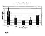
- Barrel 100 also includes porous cap 112, which is attached at the distal end of barrel 100 to permit easy filling and compression. Porous cap 112 allows gas present in barrel 100 to vent when depressing piston/plunger 102 while retaining calcium phosphate powder 101 in barrel 100. Compression of the calcium phosphate powder in the device to 0.8 g/cc or less produces a poorly and ineffectively mixed paste following hydration. The same powder, when compressed to a density of 1.0 g/cc and hydrated, is effectively and uniformly wetted and mixed.
- the mixing device also includes barrel 106, which is adapted to accept a needle, e.g., a 16-gauge needle, which is attached at the distal end of barrel 106.
- Liquid 110 e.g., USP saline
- the needle is removed from the distal end of barrel 106 and barrel 106 is coupled to barrel 100 using Luer fittings 104 to form Luer connector 105.
- the saline is injected into calcium phosphate powder 101 by depressing piston/plunger 107, which injects the saline into barrel 100.
- Barrel 100 and barrel 106 can be composed of clear polycarbonate to allow easy visualization during the venting step. Barrel 100 is reconnected to barrel 107 and mixing is performed by alternately and rapidly depressing pistons/plungers 102 and 107 several times until a uniform mixture (e.g., a paste) is formed (approximately 3-20 times). In the event not all material passes between barrel 100 and barrel 106, a series of alternating passes of plungers 107 and 102 can be performed until all material transfers and a uniform mixture is achieved.
- a uniform mixture e.g., a paste
- the narrow orifice that connects barrel 100 to barrel 146 increases shear, reduces agglomerates, and improves homogeneity and injectability of the mixture.
- the fully mixed paste is transferred into barrel 106, which is disconnected from barrel 100.
- a delivery needle or cannula (not shown) is attached to barrel 106 at Luer tip 104 and the cement can be fully extruded through the needle.
- the mixed material is injectable, i.e., capable of passing through a 7- to 18-gauge needle.
- the paste can also be prepared for delivery through a catheter (e.g., a catheter having a 7-15 gauge needle, and more preferably through a 7, 8, 9, 10, 11, 12, 13, 14, or 15-gauge needle).
- Barrel 100 and piston/plunger 102 combine to form the powder syringe, while barrel 106 and piston/plunger 107 combine to form the delivery syringe, both of which can be obtained from various industry suppliers.
- Barrel 100 and barrel 106 can be independently manufactured from glass or plastic (e.g., polypropylene, polyethylene, polycarbonate, polystyrene, and the like).
- Pistons/Plungers 102 and 107 include a plastic or glass arm attached to stopper 102 and 108, respectively.
- Barrel 100 is filled with calcium phosphate powder 110 (e.g,. any of the calcium phosphate powders described herein).
- Porous cap 112 which includes a porous polymer insert and a Luer connector, can be obtained from B.Braun (e.g,. SAFSITE® Capped Valve System; ULTRASITE® Capless Valve System).
- the mixing device can also include a standard hypodermic needle, which can be obtained from various industry suppliers.
- the powder syringe is placed into a moisture barrier tray along with a silica gel desiccant canister (e.g., a thermoformed tray inside a foil pouch may be used or a moisture barrier tray formed from a poly(ester) copolymer of terephthalic acid, ethylene-glycol and cyclohexane dimethanol known as "PETG" can be used; see, e.g., U.S. Patent No. 4,284,671 ).
- This moisture barrier configuration preserves the product (i.e., the calcium phosphate powder) by allowing moisture transmission through the porous cap so that it can be absorbed into the desiccant; the device design is particularly effective at elevated temperatures which would normally lead to cement degradation.
- the cement composition within the mixing device was degraded within 2 weeks at 50°C without desiccant, but was intact after 4 months with desiccant.
- CPC precursors Two CPC precursors; an amorphous calcium phosphate (ACP) (with Ca/P ⁇ 1.5) and dicalcium phosphate dihydrate (DCPD) seeded with apatite (10-25% w/w) were prepared using a low temperature double decomposition technique.
- the two powders were mixed at a 1:1 ratio and milled in a high-energy ball mill for 3 hours.
- the resulting powder was filled into a syringe and connected to a second syringe filled with saline by means of a luer connector.
- the saline was injected into the powder at a liquid to powder (L/P) ratio of 0.5:1 and the mixture was then passed back-and-forth between the syringes until a uniform paste was formed (approximately 5 passes).
- L/P liquid to powder
- the same cement mixed (with the same L/P) in a bowl with a spatula and then transferred into a syringe was used as a control.
- the materials were tested for chemical composition (FT-IR, XRD, and Ca:P atomic ratio) and performance characteristics (injection force and yield, working time, hardening rate, compressive strength, and resistance to washout).
- Syringe mixing reduced preparation time from two minutes to one minute, and the cement was deliverable through a 16 gauge needle with less than 3kgf force. A 50% reduction in injection force relative to bowl mixed materials was observed. Syringe mixing also increased the percentage of CPC delivered. The delivered amount was less than 90% for bowl mixed cement but was 100% for syringe mixed cement. Syringe mixed cement could be stored for up to 6 minutes at room temperature and remixed while retaining full injectability. The mixing did not affect the hardening rate, compressive strength, or resistance to washout of the CPC, nor did it change the chemical composition. The injectable cement hardened in less than 5 minutes at 37°C, achieved a compressive strength of 30 MPa in 2 hours and could be injected directly into a water bath without loss of material.
Claims (12)
- Dispositif de mélange de ciment osseux comprenant un premier tube rigide comprenant un piston mobile et un second tube rigide comprenant un piston mobile et rempli d'un liquide physiologiquement acceptable, dans lequel ledit premier tube est conçu pour être joint bout à bout audit second tube rigide de sorte qu'il existe une communication fluidique entre les tubes, et dans lequel un volume d'une poudre de ciment osseux est introduit dans ledit premier tube et, caractérisé en ce que ladite poudre est comprimée à une densité comprise entre 0,6 et 1,2 g cm-3.
- Dispositif selon la revendication 1, dans lequel :i) lesdits tubes et pistons comprennent des seringues à usage unique, et/ouii) ladite poudre de ciment osseux comprend un sel de calcium, ladite poudre de ciment osseux étant de préférence une poudre de phosphate de calcium, et/ouiii) dans lequel ledit dispositif comprend un raccord Luer qui est conçu pour joindre lesdits premier et second tubes, et/ouiv) dans lequel le dispositif comprend en outre un bouchon poreux fixé de manière amovible à la pointe dudit premier tube distale dudit piston, dans lequel ledit bouchon poreux permet l'évacuation des gaz, mais pas de ladite poudre, dudit premier tube.
- Dispositif selon la revendication 1 ou 2, dans lequel ledit dispositif comprend un rapport liquide/poudre de 0,1:1 à 50:1.
- Dispositif selon l'une quelconque des revendications 1 à 3, dans lequel le liquide est choisi parmi l'eau, une solution saline, un tampon de phosphate, et un fluide biologique et dans lequel après que lesdits premier et second tubes sont joints bout à bout, le dispositif est conçu pour mélanger ladite poudre en appuyant de façon alternée sur les pistons des premier et second tubes.
- Dispositif selon l'une quelconque des revendications 1 à 4, dans lequel ladite poudre de ciment osseux est comprimée à une densité de 1,0 g cm-3.
- Emballage comprenant un dispositif selon l'une quelconque des revendications 1 à 5 et emballage étanche à l'humidité entourant ledit dispositif, de préférence dans lequel ledit emballage comprend en outre un agent dessiccant, et en outre de préférence dans lequel l'emballage comprend un conteneur rigide ou flexible comportant une couche formant barrière perméable séparant le dispositif de l'agent dessiccant et/ou dans lequel le dispositif comprend un bouchon poreux fixé de manière amovible à une extrémité dudit premier tube distale dudit piston, dans lequel ledit bouchon poreux permet l'évacuation des gaz, mais pas de ladite poudre, dudit premier tube.
- Procédé de préparation d'un ciment osseux comprenant les étapes consistant à fournir le dispositif selon la revendication 1, dans lequel lesdits premier et second tubes sont joints bout à bout de sorte qu'il existe une communication entre les tubes qui permet au fluide de se déplacer entre les tubes et dans lequel ledit second tube comprend un liquide physiologiquement acceptable choisi de préférence parmi l'eau, une solution saline, un tampon de phosphate, et un fluide biologique, et à sensiblement mélanger ladite poudre et ledit liquide en appuyant alternativement sur les pistons desdits premier et second tubes une ou plusieurs fois pour former ledit ciment osseux.
- Procédé selon la revendication 7, comprenant en outre l'étape consistant à retirer le gaz présent dans ledit premier ou second tube avant le mélange, et de préférence dans lequel
ledit gaz est de l'air, et/ou
le retrait dudit gaz comprend les étapes consistant à déconnecter lesdits premier et second tubes, appuyer sur les pistons desdits premier et second tubes pour expulser le gaz et reconnecter lesdits premier et second tubes, et en outre de préférence dans lequel après que lesdits premier et second tubes sont déconnectés, fixer de manière amovible un bouchon poreux à une extrémité du premier tube distale du piston, dans lequel ledit bouchon poreux permet l'évacuation des gaz, mais pas de ladite poudre, dudit premier tube, retirer ledit gaz à travers ledit bouchon poreux, retirer le bouchon poreux dudit premier tube, et reconnecter les premier et second tubes. - Procédé de fabrication d'un dispositif de mélange pour la préparation d'un ciment osseux comprenant les étapes consistant à :i) remplir un premier cylindre de seringue d'une quantité de poudre de ciment osseux,ii) placer un bouchon poreux sur l'extrémité distale dudit premier cylindre de seringue, dans lequel ledit bouchon poreux est fixé de manière amovible et permet l'évacuation des gaz, mais pas de ladite poudre, dudit premier corps de seringue,iii) insérer un piston mobile dans l'extrémité proximale dudit premier cylindre de seringue et appuyer sur ledit piston en appliquant une force ou des vibrations suffisantes pour comprimer ladite poudre de ciment osseux à une densité comprise entre 0,6 et 1,2 g cm-3,iv) retirer ledit bouchon poreux,v) fournir au second cylindre de seringue une quantité d'un fluide physiologiquement acceptable, etvi) joindre l'extrémité distale dudit premier tube de seringue à l'extrémité distale dudit second cylindre de seringue de sorte qu'il existe une communication entre les cylindres permettant au fluide de se déplacer entre les cylindres, formant ainsi ledit dispositif de mélange.
- Procédé selon la revendication 9, dans lequel ladite poudre de ciment osseux est comprimée à une masse volumique de 1,0 g cm-3.
- Procédé selon la revendication 9, comprenant en outre l'étape consistant à évacuer le gaz dudit second tube rigide avant de joindre ledit second tube rigide audit premier tube rigide, ledit gaz étant de préférence de l'air.
- Procédé de conservation de poudre de ciment osseux comprenant l'étape consistant à enfermer le dispositif selon l'une quelconque des revendications 1 à 5 à l'intérieur d'un emballage étanche à l'humidité, dans lequel de préférence ledit emballage étanche à l'humidité comprend un agent dessiccant, et en outre de préférence dans lequel ledit dispositif est stocké dans un conteneur rigide ou flexible, avec une barrière perméable entre lui et l'agent dessiccant, et/ou ledit dispositif comprend un bouchon poreux fixé à l'extrémité distale dudit premier tube, dans lequel ledit bouchon poreux permet l'évacuation des gaz, mais pas de ladite poudre, dudit premier tube.
Applications Claiming Priority (2)
| Application Number | Priority Date | Filing Date | Title |
|---|---|---|---|
| US96657907P | 2007-08-29 | 2007-08-29 | |
| PCT/US2008/010214 WO2009032173A1 (fr) | 2007-08-29 | 2008-08-28 | Système de mélange et d'administration de ciment osseux et ses procédés d'utilisation |
Publications (3)
| Publication Number | Publication Date |
|---|---|
| EP2200523A1 EP2200523A1 (fr) | 2010-06-30 |
| EP2200523A4 EP2200523A4 (fr) | 2011-02-23 |
| EP2200523B1 true EP2200523B1 (fr) | 2014-05-14 |
Family
ID=40429189
Family Applications (1)
| Application Number | Title | Priority Date | Filing Date |
|---|---|---|---|
| EP08829040.8A Active EP2200523B1 (fr) | 2007-08-29 | 2008-08-28 | Système de mélange et d'administration de ciment osseux et ses procédés d'utilisation |
Country Status (8)
| Country | Link |
|---|---|
| US (1) | US9427715B2 (fr) |
| EP (1) | EP2200523B1 (fr) |
| JP (1) | JP2010537718A (fr) |
| KR (1) | KR101634664B1 (fr) |
| CN (1) | CN101835434A (fr) |
| AU (1) | AU2008296990B2 (fr) |
| CA (2) | CA2698017C (fr) |
| WO (1) | WO2009032173A1 (fr) |
Families Citing this family (55)
| Publication number | Priority date | Publication date | Assignee | Title |
|---|---|---|---|---|
| EP2394681B1 (fr) * | 2005-09-07 | 2015-01-28 | Thomas Steffen | Dispositif pour l'injection de matériau à haute viscosité |
| US9427715B2 (en) | 2007-08-29 | 2016-08-30 | Etex Corporation | Bone cement mixing and delivery system and methods of use thereof |
| JP6324653B2 (ja) | 2008-04-15 | 2018-05-16 | ライフ サイエンス エンタープライジズ インコーポレイテッド | リン酸カルシウム配合骨セメントを用いる脊椎骨の最小侵襲治療(mitv) |
| ES2554169T3 (es) * | 2008-07-15 | 2015-12-16 | Thomas Steffen | Dispositivo de inyección de cemento óseo |
| CN102232860A (zh) * | 2010-04-26 | 2011-11-09 | 邵卫星 | 一种骨水泥注入器及向骨水泥注入器中装入骨水泥的方法 |
| GB201014514D0 (en) * | 2010-09-01 | 2010-10-13 | Biocomposites Ltd | Mixing and dispensing apparatus for bone void filler |
| US8864708B1 (en) | 2010-12-03 | 2014-10-21 | Medical Device Engineering, LLC. | Tamper indicating closure assembly |
| CN108498873A (zh) * | 2010-12-13 | 2018-09-07 | 生物模拟治疗有限责任公司 | 用于脊柱融合手术的组合物和方法 |
| TWI590848B (zh) * | 2011-04-27 | 2017-07-11 | 陳瑾惠 | 用於將水泥漿送到骨腔中的方法及設備 |
| DE102011101486A1 (de) * | 2011-05-13 | 2012-11-15 | Heraeus Medical Gmbh | Vorrichtung und Verfahren zum Entgasen und Austragen von Knochenzement |
| US9604184B2 (en) | 2013-03-06 | 2017-03-28 | Orthovita, Inc. | Mixing system and valve assembly |
| US10912898B1 (en) | 2014-02-03 | 2021-02-09 | Medical Device Engineering Llc | Tamper evident cap for medical fitting |
| US10207099B1 (en) | 2014-02-21 | 2019-02-19 | Patrick Vitello | Closure assembly for medical fitting |
| US10166347B1 (en) | 2014-07-18 | 2019-01-01 | Patrick Vitello | Closure assembly for a medical device |
| US10576020B2 (en) | 2015-06-18 | 2020-03-03 | Neomed, Inc. | Syringe-to-syringe coupler |
| US10773067B2 (en) | 2014-09-08 | 2020-09-15 | Neomed, Inc. | Enteral connectors having coupling features |
| US10300263B1 (en) | 2015-02-27 | 2019-05-28 | Timothy Brandon Hunt | Closure assembly for a medical connector |
| US10166343B1 (en) | 2015-03-13 | 2019-01-01 | Timothy Brandon Hunt | Noise evident tamper cap |
| US10315024B1 (en) | 2015-03-19 | 2019-06-11 | Patick Vitello | Torque limiting closure assembly |
| CN104873264B (zh) * | 2015-06-09 | 2016-12-07 | 刘训伟 | 用于树脂类骨水泥和磷酸钙骨水泥联合灌注的设备 |
| USD825746S1 (en) | 2015-06-18 | 2018-08-14 | Neomed, Inc. | Syringe-to-syringe coupler |
| EP3424554B1 (fr) | 2015-07-15 | 2023-11-22 | Avent, Inc. | Accouplements d'adaptateur entéral |
| EP3419582B1 (fr) | 2016-02-24 | 2022-07-13 | Avent, Inc. | Raccord de transfert de fluide |
| JP2016209599A (ja) * | 2016-05-20 | 2016-12-15 | ライフ サイエンス エンタープライジズ インコーポレイテッド | リン酸カルシウム配合骨セメントを用いる脊椎骨の最小侵襲治療(mitv) |
| US10150115B2 (en) * | 2016-07-21 | 2018-12-11 | Spacepharma SA | System and method for rehydrating powder and delivering the rehydrated powder to a reactor |
| USD833006S1 (en) | 2016-11-28 | 2018-11-06 | Neomed, Inc. | Fluid transfer connector |
| US10307548B1 (en) | 2016-12-14 | 2019-06-04 | Timothy Brandon Hunt | Tracking system and method for medical devices |
| US11097071B1 (en) | 2016-12-14 | 2021-08-24 | International Medical Industries Inc. | Tamper evident assembly |
| US10953162B1 (en) | 2016-12-28 | 2021-03-23 | Timothy Brandon Hunt | Tamper evident closure assembly |
| US10758684B1 (en) | 2017-03-03 | 2020-09-01 | Jonathan J. Vitello | Tamper evident assembly |
| DE102017104854B4 (de) * | 2017-03-08 | 2019-05-29 | Heraeus Medical Gmbh | Zweiteilige Lager- und Mischvorrichtung zur Herstellung eines Knochenzements und Verfahren hierzu |
| US11040149B1 (en) | 2017-03-30 | 2021-06-22 | International Medical Industries | Tamper evident closure assembly for a medical device |
| US10888672B1 (en) | 2017-04-06 | 2021-01-12 | International Medical Industries, Inc. | Tamper evident closure assembly for a medical device |
| DE102017107569A1 (de) | 2017-04-07 | 2018-10-11 | Heraeus Medical Gmbh | Vorrichtung zum Lagern, Vermischen und Austragen eines Knochenzements und Verfahren hierzu |
| US10933202B1 (en) | 2017-05-19 | 2021-03-02 | International Medical Industries Inc. | Indicator member of low strength resistance for a tamper evident closure |
| US10898659B1 (en) | 2017-05-19 | 2021-01-26 | International Medical Industries Inc. | System for handling and dispensing a plurality of products |
| US10575887B2 (en) | 2017-08-04 | 2020-03-03 | Medtronic Holding Company Sàrl | Dispensing system and methods of use |
| US11541180B1 (en) | 2017-12-21 | 2023-01-03 | Patrick Vitello | Closure assembly having a snap-fit construction |
| US11278681B1 (en) | 2018-02-20 | 2022-03-22 | Robert Banik | Tamper evident adaptor closure |
| US11413406B1 (en) | 2018-03-05 | 2022-08-16 | Jonathan J. Vitello | Tamper evident assembly |
| US11779520B1 (en) | 2018-07-02 | 2023-10-10 | Patrick Vitello | Closure for a medical dispenser including a one-piece tip cap |
| US11793987B1 (en) | 2018-07-02 | 2023-10-24 | Patrick Vitello | Flex tec closure assembly for a medical dispenser |
| US11857751B1 (en) | 2018-07-02 | 2024-01-02 | International Medical Industries Inc. | Assembly for a medical connector |
| US11690994B1 (en) | 2018-07-13 | 2023-07-04 | Robert Banik | Modular medical connector |
| US11426328B1 (en) | 2018-08-31 | 2022-08-30 | Alexander Ollmann | Closure for a medical container |
| US11471610B1 (en) | 2018-10-18 | 2022-10-18 | Robert Banik | Asymmetrical closure for a medical device |
| USD948713S1 (en) | 2019-09-03 | 2022-04-12 | International Medical Industries, Inc. | Asymmetrical self righting tip cap |
| USD903865S1 (en) | 2018-11-19 | 2020-12-01 | International Medical Industries, Inc. | Self-righting tip cap |
| US11911339B1 (en) | 2019-08-15 | 2024-02-27 | Peter Lehel | Universal additive port cap |
| US11697527B1 (en) | 2019-09-11 | 2023-07-11 | Logan Hendren | Tamper evident closure assembly |
| US11357588B1 (en) | 2019-11-25 | 2022-06-14 | Patrick Vitello | Needle packaging and disposal assembly |
| US11904149B1 (en) | 2020-02-18 | 2024-02-20 | Jonathan Vitello | Oral tamper evident closure with retained indicator |
| US11523970B1 (en) | 2020-08-28 | 2022-12-13 | Jonathan Vitello | Tamper evident shield |
| WO2022108017A1 (fr) * | 2020-11-20 | 2022-05-27 | (주) 메드파크 | Composition de greffe osseuse |
| US11872187B1 (en) | 2020-12-28 | 2024-01-16 | Jonathan Vitello | Tamper evident seal for a vial cover |
Family Cites Families (32)
| Publication number | Priority date | Publication date | Assignee | Title |
|---|---|---|---|---|
| US3770026A (en) * | 1971-09-17 | 1973-11-06 | J Isenberg | Apparatus and method for accurately loading syringes |
| US4551135A (en) * | 1981-06-22 | 1985-11-05 | Sterling Drug Inc. | Syringe for extrusion of semi-plastic material |
| DE8420774U1 (de) * | 1984-07-11 | 1985-09-12 | Draenert, Klaus, Dr.Med. Dr.Med.Habil., 8000 Muenchen | Vorrichtung zum Mischen und Applizieren von Knochenzement |
| US4743229A (en) * | 1986-09-29 | 1988-05-10 | Collagen Corporation | Collagen/mineral mixing device and method |
| US4919153A (en) * | 1988-10-11 | 1990-04-24 | Origin Medsystems, Inc. | Method and apparatus for removing pre-placed prosthetic joints and preparing for their replacement |
| US4973168A (en) * | 1989-01-13 | 1990-11-27 | Chan Kwan Ho | Vacuum mixing/bone cement cartridge and kit |
| US5226877A (en) * | 1989-06-23 | 1993-07-13 | Epstein Gordon H | Method and apparatus for preparing fibrinogen adhesive from whole blood |
| DE9011685U1 (fr) * | 1990-08-10 | 1991-12-12 | Thera Patent Gmbh & Co. Kg Gesellschaft Fuer Industrielle Schutzrechte, 8031 Seefeld, De | |
| US5336699A (en) * | 1992-02-20 | 1994-08-09 | Orthopaedic Research Institute | Bone cement having chemically joined reinforcing fillers |
| US5676976A (en) | 1995-05-19 | 1997-10-14 | Etex Corporation | Synthesis of reactive amorphous calcium phosphates |
| US5783217A (en) | 1995-11-07 | 1998-07-21 | Etex Corporation | Low temperature calcium phosphate apatite and a method of its manufacture |
| US5902839A (en) * | 1996-12-02 | 1999-05-11 | Northwestern University | Bone cement and method of preparation |
| US7572263B2 (en) * | 1998-04-01 | 2009-08-11 | Arthrocare Corporation | High pressure applicator |
| US6709149B1 (en) * | 1998-12-14 | 2004-03-23 | Ao Research Institute Davos | Method of bone cement preparation |
| EP1244477A2 (fr) * | 1999-12-29 | 2002-10-02 | Regeneration Technologies, Inc. | Systeme servant a reconstituer des pates et procedes d'utilisation |
| WO2002017801A2 (fr) * | 2000-07-14 | 2002-03-07 | Kyphon Inc. | Systemes et methodes de traitement de corps vertebraux |
| US6592251B2 (en) * | 2001-01-26 | 2003-07-15 | Howmedica Osteonics Corp. | Cement mixing and dispensing device |
| EP1441842A4 (fr) * | 2001-10-09 | 2006-04-12 | Immedica | Systeme a composants multiples de manipulation et d'administration de produits |
| US6840961B2 (en) * | 2001-12-21 | 2005-01-11 | Etex Corporation | Machinable preformed calcium phosphate bone substitute material implants |
| AU2003228676A1 (en) | 2002-04-26 | 2003-11-10 | Surgical Sealants, Inc. | Mixing device for surgical sealants, and method thereof |
| US7776594B2 (en) * | 2002-10-10 | 2010-08-17 | Wright Medical Technology, Inc. | Bone marrow infusion chamber and method |
| AU2003214708A1 (en) * | 2003-03-14 | 2004-09-30 | Roque Humberto Ferreyro Irigoyen | Hydraulic device for the injection of bone cement in percutaneous vertebroplasty |
| WO2005069837A2 (fr) | 2004-01-13 | 2005-08-04 | Royer Biomedical, Inc. | Compositions non aqueuses pour traiter des defauts orthopediques et administrer des agents bioactifs |
| US20050209555A1 (en) * | 2004-03-18 | 2005-09-22 | Lance Middleton | Systems and methods for mixing fluids |
| US7556650B2 (en) * | 2004-06-29 | 2009-07-07 | Spine Wave, Inc. | Methods for injecting a curable biomaterial into an intervertebral space |
| US7329235B2 (en) * | 2004-08-02 | 2008-02-12 | Bertron Kim W | Powder and liquid mixing syringe |
| US8038682B2 (en) * | 2004-08-17 | 2011-10-18 | Boston Scientific Scimed, Inc. | Apparatus and methods for delivering compounds into vertebrae for vertebroplasty |
| SE530710C2 (sv) * | 2005-07-05 | 2008-08-19 | Biomet Cementing Technologies | Förfarande och anordning för att bringa en pulver- och en vätskekomponent, företrädesvis polymer och monomer, i kontakt med varandra för att blanda dessa, företrädesvis till bencement |
| US20070026030A1 (en) * | 2005-07-27 | 2007-02-01 | Berkeley Advanced Biomaterials, Inc. | Method of preparing rheological materials for bone and cartilage repair |
| US8641667B2 (en) * | 2005-10-20 | 2014-02-04 | DePuy Synthes Products, LLC | Perfusion device and method |
| US20070185495A1 (en) * | 2006-01-30 | 2007-08-09 | Howmedica International S. De R. L. | Plug-in syringe stand |
| US9427715B2 (en) | 2007-08-29 | 2016-08-30 | Etex Corporation | Bone cement mixing and delivery system and methods of use thereof |
-
2008
- 2008-08-28 US US12/675,455 patent/US9427715B2/en not_active Expired - Fee Related
- 2008-08-28 EP EP08829040.8A patent/EP2200523B1/fr active Active
- 2008-08-28 CN CN200880105069A patent/CN101835434A/zh active Pending
- 2008-08-28 CA CA2698017A patent/CA2698017C/fr active Active
- 2008-08-28 JP JP2010522956A patent/JP2010537718A/ja active Pending
- 2008-08-28 KR KR1020107005678A patent/KR101634664B1/ko active IP Right Grant
- 2008-08-28 WO PCT/US2008/010214 patent/WO2009032173A1/fr active Application Filing
- 2008-08-28 AU AU2008296990A patent/AU2008296990B2/en active Active
- 2008-08-28 CA CA2928681A patent/CA2928681C/fr active Active
Also Published As
| Publication number | Publication date |
|---|---|
| CA2698017A1 (fr) | 2009-03-12 |
| CA2698017C (fr) | 2016-12-13 |
| CA2928681A1 (fr) | 2009-03-12 |
| US9427715B2 (en) | 2016-08-30 |
| AU2008296990A1 (en) | 2009-03-12 |
| US20110112543A1 (en) | 2011-05-12 |
| WO2009032173A1 (fr) | 2009-03-12 |
| CN101835434A (zh) | 2010-09-15 |
| KR101634664B1 (ko) | 2016-06-29 |
| JP2010537718A (ja) | 2010-12-09 |
| CA2928681C (fr) | 2018-03-27 |
| EP2200523A4 (fr) | 2011-02-23 |
| KR20100061489A (ko) | 2010-06-07 |
| EP2200523A1 (fr) | 2010-06-30 |
| AU2008296990B2 (en) | 2014-12-18 |
Similar Documents
| Publication | Publication Date | Title |
|---|---|---|
| EP2200523B1 (fr) | Système de mélange et d'administration de ciment osseux et ses procédés d'utilisation | |
| US8876911B2 (en) | Delivery device for biological composites and method of preparation thereof | |
| CA2438192C (fr) | Systeme de reconstitution de pates et ses procedes d'utilisation | |
| US5037445A (en) | Method and kit for molding surgical implants | |
| EP3072538B1 (fr) | Matériau de greffe osseuse résistant au lavage, fluide, bioactif et son procédé de production | |
| US20120071884A1 (en) | Mixing and dispensing apparatus for bone void filler | |
| US8641667B2 (en) | Perfusion device and method | |
| JP2018143762A (ja) | 骨セメント製造用の二部構成の貯蔵および混合装置および関連の方法 | |
| JP2003527197A (ja) | 埋植材料用の調製および注入装置 | |
| FR3053239A1 (fr) | Susbtitut osseux et systeme d'injection autonome | |
| CA2826628C (fr) | Collagene gelifiant et moyens pour le mettre a disposition | |
| EP3043895A2 (fr) | Applicateur d'élément double | |
| US20210128780A1 (en) | Osteostimulative, bioactive and flowable bone void filler | |
| US20210161572A1 (en) | Flowable bioactive bone void filler | |
| WO2002040963A2 (fr) | Composites biologiquement actifs et procedes de production et d'utilisation correspondants | |
| WO2023212637A1 (fr) | Systèmes, procédés et dispositifs de distribution d'exosomes pour remplir des vides de fracture osseuse | |
| AU2002250192A1 (en) | System for reconstituting pastes and methods of using same |
Legal Events
| Date | Code | Title | Description |
|---|---|---|---|
| PUAI | Public reference made under article 153(3) epc to a published international application that has entered the european phase |
Free format text: ORIGINAL CODE: 0009012 |
|
| 17P | Request for examination filed |
Effective date: 20100326 |
|
| AK | Designated contracting states |
Kind code of ref document: A1 Designated state(s): AT BE BG CH CY CZ DE DK EE ES FI FR GB GR HR HU IE IS IT LI LT LU LV MC MT NL NO PL PT RO SE SI SK TR |
|
| AX | Request for extension of the european patent |
Extension state: AL BA MK RS |
|
| RIN1 | Information on inventor provided before grant (corrected) |
Inventor name: CHANG, TAK, L. Inventor name: TOFIGHI, ALIASSGHAR, N. Inventor name: SUTARIA, MANISH Inventor name: ROSENBERG, ARON, D. Inventor name: PALAZZOLO, ROBERT |
|
| RIN1 | Information on inventor provided before grant (corrected) |
Inventor name: ROSENBERG, ARON, D. Inventor name: CHANG, TAK, L. Inventor name: TOFIGHI, ALIASSGHAR, N. Inventor name: SUTARIA, MANISH Inventor name: PALAZZOLO, ROBERT |
|
| DAX | Request for extension of the european patent (deleted) | ||
| A4 | Supplementary search report drawn up and despatched |
Effective date: 20110126 |
|
| RIC1 | Information provided on ipc code assigned before grant |
Ipc: B01F 11/00 20060101ALI20110120BHEP Ipc: B01F 5/06 20060101ALI20110120BHEP Ipc: A61F 2/00 20060101ALI20110120BHEP Ipc: A61B 17/58 20060101AFI20090326BHEP Ipc: A61B 17/60 20060101ALI20110120BHEP |
|
| 17Q | First examination report despatched |
Effective date: 20111004 |
|
| REG | Reference to a national code |
Ref country code: DE Ref legal event code: R079 Ref document number: 602008032311 Country of ref document: DE Free format text: PREVIOUS MAIN CLASS: A61B0017580000 Ipc: A61B0017880000 |
|
| GRAP | Despatch of communication of intention to grant a patent |
Free format text: ORIGINAL CODE: EPIDOSNIGR1 |
|
| RIC1 | Information provided on ipc code assigned before grant |
Ipc: B01F 15/02 20060101ALI20131104BHEP Ipc: A61B 17/88 20060101AFI20131104BHEP |
|
| INTG | Intention to grant announced |
Effective date: 20131206 |
|
| RIN1 | Information on inventor provided before grant (corrected) |
Inventor name: SUTARIA, MANISH Inventor name: ROSENBERG, ARON, D. Inventor name: TOFIGHI, ALIASSGHAR, N. Inventor name: PALAZZOLO, ROBERT Inventor name: CHANG, TAK, L. |
|
| GRAS | Grant fee paid |
Free format text: ORIGINAL CODE: EPIDOSNIGR3 |
|
| GRAA | (expected) grant |
Free format text: ORIGINAL CODE: 0009210 |
|
| AK | Designated contracting states |
Kind code of ref document: B1 Designated state(s): AT BE BG CH CY CZ DE DK EE ES FI FR GB GR HR HU IE IS IT LI LT LU LV MC MT NL NO PL PT RO SE SI SK TR |
|
| REG | Reference to a national code |
Ref country code: GB Ref legal event code: FG4D |
|
| REG | Reference to a national code |
Ref country code: AT Ref legal event code: REF Ref document number: 667643 Country of ref document: AT Kind code of ref document: T Effective date: 20140615 |
|
| REG | Reference to a national code |
Ref country code: IE Ref legal event code: FG4D |
|
| REG | Reference to a national code |
Ref country code: DE Ref legal event code: R096 Ref document number: 602008032311 Country of ref document: DE Effective date: 20140626 |
|
| RAP2 | Party data changed (patent owner data changed or rights of a patent transferred) |
Owner name: ETEX CORPORATION |
|
| REG | Reference to a national code |
Ref country code: NL Ref legal event code: VDEP Effective date: 20140514 Ref country code: AT Ref legal event code: MK05 Ref document number: 667643 Country of ref document: AT Kind code of ref document: T Effective date: 20140514 |
|
| REG | Reference to a national code |
Ref country code: LT Ref legal event code: MG4D |
|
| PG25 | Lapsed in a contracting state [announced via postgrant information from national office to epo] |
Ref country code: NO Free format text: LAPSE BECAUSE OF FAILURE TO SUBMIT A TRANSLATION OF THE DESCRIPTION OR TO PAY THE FEE WITHIN THE PRESCRIBED TIME-LIMIT Effective date: 20140814 Ref country code: FI Free format text: LAPSE BECAUSE OF FAILURE TO SUBMIT A TRANSLATION OF THE DESCRIPTION OR TO PAY THE FEE WITHIN THE PRESCRIBED TIME-LIMIT Effective date: 20140514 Ref country code: IS Free format text: LAPSE BECAUSE OF FAILURE TO SUBMIT A TRANSLATION OF THE DESCRIPTION OR TO PAY THE FEE WITHIN THE PRESCRIBED TIME-LIMIT Effective date: 20140914 Ref country code: CY Free format text: LAPSE BECAUSE OF FAILURE TO SUBMIT A TRANSLATION OF THE DESCRIPTION OR TO PAY THE FEE WITHIN THE PRESCRIBED TIME-LIMIT Effective date: 20140514 Ref country code: GR Free format text: LAPSE BECAUSE OF FAILURE TO SUBMIT A TRANSLATION OF THE DESCRIPTION OR TO PAY THE FEE WITHIN THE PRESCRIBED TIME-LIMIT Effective date: 20140815 Ref country code: LT Free format text: LAPSE BECAUSE OF FAILURE TO SUBMIT A TRANSLATION OF THE DESCRIPTION OR TO PAY THE FEE WITHIN THE PRESCRIBED TIME-LIMIT Effective date: 20140514 |
|
| PG25 | Lapsed in a contracting state [announced via postgrant information from national office to epo] |
Ref country code: AT Free format text: LAPSE BECAUSE OF FAILURE TO SUBMIT A TRANSLATION OF THE DESCRIPTION OR TO PAY THE FEE WITHIN THE PRESCRIBED TIME-LIMIT Effective date: 20140514 Ref country code: PL Free format text: LAPSE BECAUSE OF FAILURE TO SUBMIT A TRANSLATION OF THE DESCRIPTION OR TO PAY THE FEE WITHIN THE PRESCRIBED TIME-LIMIT Effective date: 20140514 Ref country code: LV Free format text: LAPSE BECAUSE OF FAILURE TO SUBMIT A TRANSLATION OF THE DESCRIPTION OR TO PAY THE FEE WITHIN THE PRESCRIBED TIME-LIMIT Effective date: 20140514 Ref country code: SE Free format text: LAPSE BECAUSE OF FAILURE TO SUBMIT A TRANSLATION OF THE DESCRIPTION OR TO PAY THE FEE WITHIN THE PRESCRIBED TIME-LIMIT Effective date: 20140514 Ref country code: HR Free format text: LAPSE BECAUSE OF FAILURE TO SUBMIT A TRANSLATION OF THE DESCRIPTION OR TO PAY THE FEE WITHIN THE PRESCRIBED TIME-LIMIT Effective date: 20140514 Ref country code: ES Free format text: LAPSE BECAUSE OF FAILURE TO SUBMIT A TRANSLATION OF THE DESCRIPTION OR TO PAY THE FEE WITHIN THE PRESCRIBED TIME-LIMIT Effective date: 20140514 |
|
| PG25 | Lapsed in a contracting state [announced via postgrant information from national office to epo] |
Ref country code: PT Free format text: LAPSE BECAUSE OF FAILURE TO SUBMIT A TRANSLATION OF THE DESCRIPTION OR TO PAY THE FEE WITHIN THE PRESCRIBED TIME-LIMIT Effective date: 20140915 |
|
| PG25 | Lapsed in a contracting state [announced via postgrant information from national office to epo] |
Ref country code: RO Free format text: LAPSE BECAUSE OF FAILURE TO SUBMIT A TRANSLATION OF THE DESCRIPTION OR TO PAY THE FEE WITHIN THE PRESCRIBED TIME-LIMIT Effective date: 20140514 Ref country code: EE Free format text: LAPSE BECAUSE OF FAILURE TO SUBMIT A TRANSLATION OF THE DESCRIPTION OR TO PAY THE FEE WITHIN THE PRESCRIBED TIME-LIMIT Effective date: 20140514 Ref country code: DK Free format text: LAPSE BECAUSE OF FAILURE TO SUBMIT A TRANSLATION OF THE DESCRIPTION OR TO PAY THE FEE WITHIN THE PRESCRIBED TIME-LIMIT Effective date: 20140514 Ref country code: SK Free format text: LAPSE BECAUSE OF FAILURE TO SUBMIT A TRANSLATION OF THE DESCRIPTION OR TO PAY THE FEE WITHIN THE PRESCRIBED TIME-LIMIT Effective date: 20140514 Ref country code: BE Free format text: LAPSE BECAUSE OF FAILURE TO SUBMIT A TRANSLATION OF THE DESCRIPTION OR TO PAY THE FEE WITHIN THE PRESCRIBED TIME-LIMIT Effective date: 20140514 Ref country code: CZ Free format text: LAPSE BECAUSE OF FAILURE TO SUBMIT A TRANSLATION OF THE DESCRIPTION OR TO PAY THE FEE WITHIN THE PRESCRIBED TIME-LIMIT Effective date: 20140514 |
|
| REG | Reference to a national code |
Ref country code: DE Ref legal event code: R097 Ref document number: 602008032311 Country of ref document: DE |
|
| PG25 | Lapsed in a contracting state [announced via postgrant information from national office to epo] |
Ref country code: NL Free format text: LAPSE BECAUSE OF FAILURE TO SUBMIT A TRANSLATION OF THE DESCRIPTION OR TO PAY THE FEE WITHIN THE PRESCRIBED TIME-LIMIT Effective date: 20140514 |
|
| REG | Reference to a national code |
Ref country code: DE Ref legal event code: R082 Ref document number: 602008032311 Country of ref document: DE Effective date: 20150303 Ref country code: DE Ref legal event code: R081 Ref document number: 602008032311 Country of ref document: DE Owner name: ETEX HOLDINGS, INC. (N.D.GES.D. STAATES DELAWA, US Free format text: FORMER OWNER: ETEX CORP., CAMBRIDGE, MASS., US Effective date: 20150129 |
|
| PLBE | No opposition filed within time limit |
Free format text: ORIGINAL CODE: 0009261 |
|
| STAA | Information on the status of an ep patent application or granted ep patent |
Free format text: STATUS: NO OPPOSITION FILED WITHIN TIME LIMIT |
|
| PG25 | Lapsed in a contracting state [announced via postgrant information from national office to epo] |
Ref country code: MC Free format text: LAPSE BECAUSE OF FAILURE TO SUBMIT A TRANSLATION OF THE DESCRIPTION OR TO PAY THE FEE WITHIN THE PRESCRIBED TIME-LIMIT Effective date: 20140514 Ref country code: LU Free format text: LAPSE BECAUSE OF FAILURE TO SUBMIT A TRANSLATION OF THE DESCRIPTION OR TO PAY THE FEE WITHIN THE PRESCRIBED TIME-LIMIT Effective date: 20140828 |
|
| REG | Reference to a national code |
Ref country code: CH Ref legal event code: PL |
|
| 26N | No opposition filed |
Effective date: 20150217 |
|
| PG25 | Lapsed in a contracting state [announced via postgrant information from national office to epo] |
Ref country code: BE Free format text: LAPSE BECAUSE OF FAILURE TO SUBMIT A TRANSLATION OF THE DESCRIPTION OR TO PAY THE FEE WITHIN THE PRESCRIBED TIME-LIMIT Effective date: 20140831 Ref country code: CH Free format text: LAPSE BECAUSE OF NON-PAYMENT OF DUE FEES Effective date: 20140831 Ref country code: LI Free format text: LAPSE BECAUSE OF NON-PAYMENT OF DUE FEES Effective date: 20140831 |
|
| REG | Reference to a national code |
Ref country code: IE Ref legal event code: MM4A |
|
| REG | Reference to a national code |
Ref country code: DE Ref legal event code: R097 Ref document number: 602008032311 Country of ref document: DE Effective date: 20150217 |
|
| REG | Reference to a national code |
Ref country code: FR Ref legal event code: PLFP Year of fee payment: 8 |
|
| PG25 | Lapsed in a contracting state [announced via postgrant information from national office to epo] |
Ref country code: SI Free format text: LAPSE BECAUSE OF FAILURE TO SUBMIT A TRANSLATION OF THE DESCRIPTION OR TO PAY THE FEE WITHIN THE PRESCRIBED TIME-LIMIT Effective date: 20140514 |
|
| PG25 | Lapsed in a contracting state [announced via postgrant information from national office to epo] |
Ref country code: IE Free format text: LAPSE BECAUSE OF NON-PAYMENT OF DUE FEES Effective date: 20140828 |
|
| PG25 | Lapsed in a contracting state [announced via postgrant information from national office to epo] |
Ref country code: BG Free format text: LAPSE BECAUSE OF FAILURE TO SUBMIT A TRANSLATION OF THE DESCRIPTION OR TO PAY THE FEE WITHIN THE PRESCRIBED TIME-LIMIT Effective date: 20140514 |
|
| PG25 | Lapsed in a contracting state [announced via postgrant information from national office to epo] |
Ref country code: MT Free format text: LAPSE BECAUSE OF FAILURE TO SUBMIT A TRANSLATION OF THE DESCRIPTION OR TO PAY THE FEE WITHIN THE PRESCRIBED TIME-LIMIT Effective date: 20140514 |
|
| REG | Reference to a national code |
Ref country code: FR Ref legal event code: PLFP Year of fee payment: 9 |
|
| PG25 | Lapsed in a contracting state [announced via postgrant information from national office to epo] |
Ref country code: TR Free format text: LAPSE BECAUSE OF FAILURE TO SUBMIT A TRANSLATION OF THE DESCRIPTION OR TO PAY THE FEE WITHIN THE PRESCRIBED TIME-LIMIT Effective date: 20140514 Ref country code: HU Free format text: LAPSE BECAUSE OF FAILURE TO SUBMIT A TRANSLATION OF THE DESCRIPTION OR TO PAY THE FEE WITHIN THE PRESCRIBED TIME-LIMIT; INVALID AB INITIO Effective date: 20080828 |
|
| REG | Reference to a national code |
Ref country code: FR Ref legal event code: PLFP Year of fee payment: 10 |
|
| REG | Reference to a national code |
Ref country code: FR Ref legal event code: PLFP Year of fee payment: 11 |
|
| PGFP | Annual fee paid to national office [announced via postgrant information from national office to epo] |
Ref country code: IT Payment date: 20230711 Year of fee payment: 16 Ref country code: GB Payment date: 20230705 Year of fee payment: 16 |
|
| PGFP | Annual fee paid to national office [announced via postgrant information from national office to epo] |
Ref country code: FR Payment date: 20230706 Year of fee payment: 16 Ref country code: DE Payment date: 20230705 Year of fee payment: 16 |