EP2199552B1 - Exhaust gas purification system of diesel engine - Google Patents
Exhaust gas purification system of diesel engine Download PDFInfo
- Publication number
- EP2199552B1 EP2199552B1 EP08778251.2A EP08778251A EP2199552B1 EP 2199552 B1 EP2199552 B1 EP 2199552B1 EP 08778251 A EP08778251 A EP 08778251A EP 2199552 B1 EP2199552 B1 EP 2199552B1
- Authority
- EP
- European Patent Office
- Prior art keywords
- pressure
- filter
- dpf
- differential pressure
- correction
- Prior art date
- Legal status (The legal status is an assumption and is not a legal conclusion. Google has not performed a legal analysis and makes no representation as to the accuracy of the status listed.)
- Not-in-force
Links
Images


Classifications
-
- F—MECHANICAL ENGINEERING; LIGHTING; HEATING; WEAPONS; BLASTING
- F01—MACHINES OR ENGINES IN GENERAL; ENGINE PLANTS IN GENERAL; STEAM ENGINES
- F01N—GAS-FLOW SILENCERS OR EXHAUST APPARATUS FOR MACHINES OR ENGINES IN GENERAL; GAS-FLOW SILENCERS OR EXHAUST APPARATUS FOR INTERNAL-COMBUSTION ENGINES
- F01N9/00—Electrical control of exhaust gas treating apparatus
- F01N9/002—Electrical control of exhaust gas treating apparatus of filter regeneration
-
- F—MECHANICAL ENGINEERING; LIGHTING; HEATING; WEAPONS; BLASTING
- F01—MACHINES OR ENGINES IN GENERAL; ENGINE PLANTS IN GENERAL; STEAM ENGINES
- F01N—GAS-FLOW SILENCERS OR EXHAUST APPARATUS FOR MACHINES OR ENGINES IN GENERAL; GAS-FLOW SILENCERS OR EXHAUST APPARATUS FOR INTERNAL-COMBUSTION ENGINES
- F01N3/00—Exhaust or silencing apparatus having means for purifying, rendering innocuous, or otherwise treating exhaust
- F01N3/02—Exhaust or silencing apparatus having means for purifying, rendering innocuous, or otherwise treating exhaust for cooling, or for removing solid constituents of, exhaust
-
- B—PERFORMING OPERATIONS; TRANSPORTING
- B01—PHYSICAL OR CHEMICAL PROCESSES OR APPARATUS IN GENERAL
- B01D—SEPARATION
- B01D46/00—Filters or filtering processes specially modified for separating dispersed particles from gases or vapours
- B01D46/42—Auxiliary equipment or operation thereof
-
- F—MECHANICAL ENGINEERING; LIGHTING; HEATING; WEAPONS; BLASTING
- F01—MACHINES OR ENGINES IN GENERAL; ENGINE PLANTS IN GENERAL; STEAM ENGINES
- F01N—GAS-FLOW SILENCERS OR EXHAUST APPARATUS FOR MACHINES OR ENGINES IN GENERAL; GAS-FLOW SILENCERS OR EXHAUST APPARATUS FOR INTERNAL-COMBUSTION ENGINES
- F01N13/00—Exhaust or silencing apparatus characterised by constructional features
- F01N13/009—Exhaust or silencing apparatus characterised by constructional features having two or more separate purifying devices arranged in series
- F01N13/0097—Exhaust or silencing apparatus characterised by constructional features having two or more separate purifying devices arranged in series the purifying devices are arranged in a single housing
-
- F—MECHANICAL ENGINEERING; LIGHTING; HEATING; WEAPONS; BLASTING
- F01—MACHINES OR ENGINES IN GENERAL; ENGINE PLANTS IN GENERAL; STEAM ENGINES
- F01N—GAS-FLOW SILENCERS OR EXHAUST APPARATUS FOR MACHINES OR ENGINES IN GENERAL; GAS-FLOW SILENCERS OR EXHAUST APPARATUS FOR INTERNAL-COMBUSTION ENGINES
- F01N3/00—Exhaust or silencing apparatus having means for purifying, rendering innocuous, or otherwise treating exhaust
- F01N3/02—Exhaust or silencing apparatus having means for purifying, rendering innocuous, or otherwise treating exhaust for cooling, or for removing solid constituents of, exhaust
- F01N3/021—Exhaust or silencing apparatus having means for purifying, rendering innocuous, or otherwise treating exhaust for cooling, or for removing solid constituents of, exhaust by means of filters
- F01N3/023—Exhaust or silencing apparatus having means for purifying, rendering innocuous, or otherwise treating exhaust for cooling, or for removing solid constituents of, exhaust by means of filters using means for regenerating the filters, e.g. by burning trapped particles
- F01N3/025—Exhaust or silencing apparatus having means for purifying, rendering innocuous, or otherwise treating exhaust for cooling, or for removing solid constituents of, exhaust by means of filters using means for regenerating the filters, e.g. by burning trapped particles using fuel burner or by adding fuel to exhaust
- F01N3/0253—Exhaust or silencing apparatus having means for purifying, rendering innocuous, or otherwise treating exhaust for cooling, or for removing solid constituents of, exhaust by means of filters using means for regenerating the filters, e.g. by burning trapped particles using fuel burner or by adding fuel to exhaust adding fuel to exhaust gases
-
- F—MECHANICAL ENGINEERING; LIGHTING; HEATING; WEAPONS; BLASTING
- F01—MACHINES OR ENGINES IN GENERAL; ENGINE PLANTS IN GENERAL; STEAM ENGINES
- F01N—GAS-FLOW SILENCERS OR EXHAUST APPARATUS FOR MACHINES OR ENGINES IN GENERAL; GAS-FLOW SILENCERS OR EXHAUST APPARATUS FOR INTERNAL-COMBUSTION ENGINES
- F01N3/00—Exhaust or silencing apparatus having means for purifying, rendering innocuous, or otherwise treating exhaust
- F01N3/02—Exhaust or silencing apparatus having means for purifying, rendering innocuous, or otherwise treating exhaust for cooling, or for removing solid constituents of, exhaust
- F01N3/021—Exhaust or silencing apparatus having means for purifying, rendering innocuous, or otherwise treating exhaust for cooling, or for removing solid constituents of, exhaust by means of filters
- F01N3/033—Exhaust or silencing apparatus having means for purifying, rendering innocuous, or otherwise treating exhaust for cooling, or for removing solid constituents of, exhaust by means of filters in combination with other devices
- F01N3/035—Exhaust or silencing apparatus having means for purifying, rendering innocuous, or otherwise treating exhaust for cooling, or for removing solid constituents of, exhaust by means of filters in combination with other devices with catalytic reactors
-
- F—MECHANICAL ENGINEERING; LIGHTING; HEATING; WEAPONS; BLASTING
- F01—MACHINES OR ENGINES IN GENERAL; ENGINE PLANTS IN GENERAL; STEAM ENGINES
- F01N—GAS-FLOW SILENCERS OR EXHAUST APPARATUS FOR MACHINES OR ENGINES IN GENERAL; GAS-FLOW SILENCERS OR EXHAUST APPARATUS FOR INTERNAL-COMBUSTION ENGINES
- F01N3/00—Exhaust or silencing apparatus having means for purifying, rendering innocuous, or otherwise treating exhaust
- F01N3/08—Exhaust or silencing apparatus having means for purifying, rendering innocuous, or otherwise treating exhaust for rendering innocuous
- F01N3/10—Exhaust or silencing apparatus having means for purifying, rendering innocuous, or otherwise treating exhaust for rendering innocuous by thermal or catalytic conversion of noxious components of exhaust
- F01N3/105—General auxiliary catalysts, e.g. upstream or downstream of the main catalyst
- F01N3/106—Auxiliary oxidation catalysts
-
- F—MECHANICAL ENGINEERING; LIGHTING; HEATING; WEAPONS; BLASTING
- F01—MACHINES OR ENGINES IN GENERAL; ENGINE PLANTS IN GENERAL; STEAM ENGINES
- F01N—GAS-FLOW SILENCERS OR EXHAUST APPARATUS FOR MACHINES OR ENGINES IN GENERAL; GAS-FLOW SILENCERS OR EXHAUST APPARATUS FOR INTERNAL-COMBUSTION ENGINES
- F01N9/00—Electrical control of exhaust gas treating apparatus
-
- F—MECHANICAL ENGINEERING; LIGHTING; HEATING; WEAPONS; BLASTING
- F01—MACHINES OR ENGINES IN GENERAL; ENGINE PLANTS IN GENERAL; STEAM ENGINES
- F01N—GAS-FLOW SILENCERS OR EXHAUST APPARATUS FOR MACHINES OR ENGINES IN GENERAL; GAS-FLOW SILENCERS OR EXHAUST APPARATUS FOR INTERNAL-COMBUSTION ENGINES
- F01N2550/00—Monitoring or diagnosing the deterioration of exhaust systems
- F01N2550/04—Filtering activity of particulate filters
-
- F—MECHANICAL ENGINEERING; LIGHTING; HEATING; WEAPONS; BLASTING
- F01—MACHINES OR ENGINES IN GENERAL; ENGINE PLANTS IN GENERAL; STEAM ENGINES
- F01N—GAS-FLOW SILENCERS OR EXHAUST APPARATUS FOR MACHINES OR ENGINES IN GENERAL; GAS-FLOW SILENCERS OR EXHAUST APPARATUS FOR INTERNAL-COMBUSTION ENGINES
- F01N2560/00—Exhaust systems with means for detecting or measuring exhaust gas components or characteristics
- F01N2560/06—Exhaust systems with means for detecting or measuring exhaust gas components or characteristics the means being a temperature sensor
-
- F—MECHANICAL ENGINEERING; LIGHTING; HEATING; WEAPONS; BLASTING
- F01—MACHINES OR ENGINES IN GENERAL; ENGINE PLANTS IN GENERAL; STEAM ENGINES
- F01N—GAS-FLOW SILENCERS OR EXHAUST APPARATUS FOR MACHINES OR ENGINES IN GENERAL; GAS-FLOW SILENCERS OR EXHAUST APPARATUS FOR INTERNAL-COMBUSTION ENGINES
- F01N2560/00—Exhaust systems with means for detecting or measuring exhaust gas components or characteristics
- F01N2560/08—Exhaust systems with means for detecting or measuring exhaust gas components or characteristics the means being a pressure sensor
-
- F—MECHANICAL ENGINEERING; LIGHTING; HEATING; WEAPONS; BLASTING
- F01—MACHINES OR ENGINES IN GENERAL; ENGINE PLANTS IN GENERAL; STEAM ENGINES
- F01N—GAS-FLOW SILENCERS OR EXHAUST APPARATUS FOR MACHINES OR ENGINES IN GENERAL; GAS-FLOW SILENCERS OR EXHAUST APPARATUS FOR INTERNAL-COMBUSTION ENGINES
- F01N2560/00—Exhaust systems with means for detecting or measuring exhaust gas components or characteristics
- F01N2560/14—Exhaust systems with means for detecting or measuring exhaust gas components or characteristics having more than one sensor of one kind
-
- F—MECHANICAL ENGINEERING; LIGHTING; HEATING; WEAPONS; BLASTING
- F01—MACHINES OR ENGINES IN GENERAL; ENGINE PLANTS IN GENERAL; STEAM ENGINES
- F01N—GAS-FLOW SILENCERS OR EXHAUST APPARATUS FOR MACHINES OR ENGINES IN GENERAL; GAS-FLOW SILENCERS OR EXHAUST APPARATUS FOR INTERNAL-COMBUSTION ENGINES
- F01N2610/00—Adding substances to exhaust gases
- F01N2610/14—Arrangements for the supply of substances, e.g. conduits
- F01N2610/1453—Sprayers or atomisers; Arrangement thereof in the exhaust apparatus
- F01N2610/146—Control thereof, e.g. control of injectors or injection valves
-
- F—MECHANICAL ENGINEERING; LIGHTING; HEATING; WEAPONS; BLASTING
- F01—MACHINES OR ENGINES IN GENERAL; ENGINE PLANTS IN GENERAL; STEAM ENGINES
- F01N—GAS-FLOW SILENCERS OR EXHAUST APPARATUS FOR MACHINES OR ENGINES IN GENERAL; GAS-FLOW SILENCERS OR EXHAUST APPARATUS FOR INTERNAL-COMBUSTION ENGINES
- F01N2900/00—Details of electrical control or of the monitoring of the exhaust gas treating apparatus
- F01N2900/04—Methods of control or diagnosing
- F01N2900/0408—Methods of control or diagnosing using a feed-back loop
-
- F—MECHANICAL ENGINEERING; LIGHTING; HEATING; WEAPONS; BLASTING
- F01—MACHINES OR ENGINES IN GENERAL; ENGINE PLANTS IN GENERAL; STEAM ENGINES
- F01N—GAS-FLOW SILENCERS OR EXHAUST APPARATUS FOR MACHINES OR ENGINES IN GENERAL; GAS-FLOW SILENCERS OR EXHAUST APPARATUS FOR INTERNAL-COMBUSTION ENGINES
- F01N2900/00—Details of electrical control or of the monitoring of the exhaust gas treating apparatus
- F01N2900/04—Methods of control or diagnosing
- F01N2900/0416—Methods of control or diagnosing using the state of a sensor, e.g. of an exhaust gas sensor
-
- F—MECHANICAL ENGINEERING; LIGHTING; HEATING; WEAPONS; BLASTING
- F01—MACHINES OR ENGINES IN GENERAL; ENGINE PLANTS IN GENERAL; STEAM ENGINES
- F01N—GAS-FLOW SILENCERS OR EXHAUST APPARATUS FOR MACHINES OR ENGINES IN GENERAL; GAS-FLOW SILENCERS OR EXHAUST APPARATUS FOR INTERNAL-COMBUSTION ENGINES
- F01N2900/00—Details of electrical control or of the monitoring of the exhaust gas treating apparatus
- F01N2900/06—Parameters used for exhaust control or diagnosing
- F01N2900/14—Parameters used for exhaust control or diagnosing said parameters being related to the exhaust gas
-
- Y—GENERAL TAGGING OF NEW TECHNOLOGICAL DEVELOPMENTS; GENERAL TAGGING OF CROSS-SECTIONAL TECHNOLOGIES SPANNING OVER SEVERAL SECTIONS OF THE IPC; TECHNICAL SUBJECTS COVERED BY FORMER USPC CROSS-REFERENCE ART COLLECTIONS [XRACs] AND DIGESTS
- Y02—TECHNOLOGIES OR APPLICATIONS FOR MITIGATION OR ADAPTATION AGAINST CLIMATE CHANGE
- Y02T—CLIMATE CHANGE MITIGATION TECHNOLOGIES RELATED TO TRANSPORTATION
- Y02T10/00—Road transport of goods or passengers
- Y02T10/10—Internal combustion engine [ICE] based vehicles
- Y02T10/40—Engine management systems
Definitions
- the present invention relates generally to cleaning systems for exhaust gas emissions from diesel engines mounted in construction machines. More particularly, the invention concerns a diesel engine exhaust gas cleaning system adapted for computing a differential pressure across a filter and using this computed differential pressure to judge whether any particulate matter deposited in the filter is to be removed by burning-off to regenerate the filter.
- the DPF traps the PM included in the exhaust gases emitted from a diesel engine, and thus reduces the amount of PM emitted into the atmosphere.
- the DPF burns and removes trapped PM deposits to recover (regenerate) the PM-trapping ability of the filter.
- the PM deposited in the DPF is exposed to exhaust gases of a temperature higher than a fixed level and removed by burning (this process is referred to as natural regeneration of the filter).
- the natural regeneration of the DPF does not occur and if this DPF state remains unimproved, excessive PM deposition will clog the DPF.
- Patent Document 1 describes a technique for detecting a differential pressure across a DPF by supplying pressures from the upstream and downstream sides of the DPF through pressure-introducing lines to one differential pressure sensor and detecting the differential pressure across the DPF.
- Patent Document 2 describes a technique for detecting a differential pressure across a DPF by detecting pressures by means of pressure sensors provided at the upstream and downstream sides of the DPF, and taking the difference.
- US 4574589 A discloses a filter or trap disposed in the exhaust passage of a diesel engines in order to trap any particulate matter included in exhaust gases, and a filter unclogging device or burner disposed in the exhaust passage at a point upstream of the filter or trap.
- An object of the present invention is to provide a diesel engine exhaust gas cleaning system that can measure a differential pressure across a filter accurately by using simply constructed and highly durable sensors during detection of the differential pressure across the filter.
- a differential pressure across a filter can be measured accurately by using simply constructed and highly durable sensors during the detection of the differential pressure across the filter.
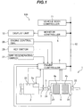
- Fig. 1 is a diagram showing a system for cleaning exhaust gas emissions from an engineering vehicle according to an embodiment of the present invention, the diagram also showing an engine control system.
- reference numeral 2 denotes a diesel engine 2 (hereinafter, referred to simply as the engine), the engine 2 including an electronic governor 2a for controlling a speed of the engine 2, and an exhaust pipe 3 for releasing the exhaust gases from the engine 2 to the outside.
- the engine 2 including an electronic governor 2a for controlling a speed of the engine 2, and an exhaust pipe 3 for releasing the exhaust gases from the engine 2 to the outside.
- Reference numeral 100 denotes the engine control system, which includes a key switch 20 for assigning a starting instruction to the engine 2, an engine control dial 26 for specifying a target speed for the engine 2, an engine speed sensor 25 for detecting an actual speed of the engine 2, and an engine controller 8 for conducting required computing processes based upon incoming signals from the key switch 20, the engine control dial 26, and the engine speed sensor 25, and then transmitting control signals as outputs to the electronic governor 2a.
- the engine controller 8 is connected to a vehicle body controller 11 that controls operation of the entire engineering vehicle, and exchanges various information with the vehicle body controller 11 via a vehicle body network 12.
- the engine control system 100 also has the exhaust gas cleaning system 1 of the present embodiment.
- the exhaust gas cleaning system 1 equipped midway in the exhaust pipe 3 includes a filter 4b for trapping any particulate matter (hereinafter, referred to simply as PM) included in the exhaust gas emissions from the engine 2, a diesel particulate filter 4 (hereinafter, referred to simply as DPF) positioned at an upstream side of the filter 4b and having an oxidizing catalyst 4a, a first temperature sensor 23 and second temperature sensor 24 for detecting internal temperatures of the exhaust pipe 3 at upstream and downstream sides, respectively, of the DPF 4, a first pressure sensor 21 and second pressure sensor 22 for detecting internal pressures of the exhaust pipe 3 at the upstream and downstream sides, respectively, of the DPF 4, and a DPF regenerating switch 27 for specifying regeneration control (described later herein) of the DPF 4.
- PM particulate matter
- DPF diesel particulate filter 4
- the engine controller 8 uses the signals to conduct a computing process required for the exhaust gas cleaning system 1.
- the exhaust gas cleaning system 1 also includes a display unit 10 and a monitor controller 9 for controlling the display unit 10.
- the monitor controller 9 is connected to the vehicle body network 12, and various information (described later herein) that is based upon processing results of the engine controller 8 is sent to the monitor controller 9 and displayed on the display unit 10.
- the exhaust gas cleaning system 1 further has a regenerating fuel injector 7 at the upstream side of the DPF 4 to inject an unburnt fuel on the basis of the processing results of the engine controller 8.
- the key switch 20, the engine control dial 26, the DPF regenerating switch 27, and the display unit 10 are arranged in a cabin (not shown) of the engineering vehicle so as to allow easy operations by an operator.
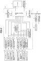
- Fig. 2 is a functional block diagram that shows details of processing functions of the engine controller 8.
- the engine controller 8 has functions of a key switch state discriminating unit 30, a first pressure sensor output data computing unit 31, a second pressure sensor output data computing unit 32, a first temperature sensor output data computing unit 33, a second temperature sensor output data computing unit 34, an engine speed computing unit 35, an engine target speed computing unit 36, a DPF regenerating switch state discriminating unit 37, a differential temperature computing unit 40, a sensor error discriminating unit 41, a correction data storage unit 42, an engine control unit 50, and a communications unit 43.
- the key switch state discriminating unit 30 and the DPF regenerating switch state discriminating unit 37 receive switch signals as input signals from the key switch 20 and the DPF regenerating switch 27, respectively, and transmit respective discrimination results as output signals to the engine control unit 50.
- the first pressure computing unit 31 and the second pressure computing unit 32 receive input signals from the first pressure sensor 21 and the second pressure sensor 22, respectively, and transmit associated computing results as a first pressure and a second pressure, respectively, to the engine control unit 50.
- the first temperature sensor output data computing unit 33 and the second temperature sensor output data computing unit 34 receive input signals from the first temperature sensor 23 and the second temperature sensor 24, respectively, and transmit associated computing results as a first temperature and a second temperature, respectively, to the differential temperature computing unit 40 and the engine control unit 50.
- the engine speed computing unit 35 receives an input signal from the engine speed sensor 25 and transmits associated computing results (computed engine speed) as an output signal to the engine control unit 50.
- the engine target speed computing unit 36 receives a voltage signal as an input signal from the engine control dial 26 and transmits associated computing results (computed engine target speed) as an output signal to the engine control unit 50.
- the sensor error discriminating unit 41 receives input signals from the first pressure computing unit 31, the second pressure computing unit 32, the first temperature computing unit 33, the second temperature computing unit 34, and the engine speed computing unit 35, and after using these signals to discriminate any errors in the sensors 21-25, transmits associated discrimination results to the engine control unit 50.
- the correction data storage unit 42 acquires first pressure and second pressure correction data (described later herein) that has been computed by the engine control unit 50.
- the communications unit 43 is connected to the monitor controller 9 and the vehicle body controller 11 via the vehicle body network 12. In addition to transferring information from the engine control unit 50 to the monitor controller 9 and the vehicle body controller 11, the communications unit 43 transfers information from the monitor controller 9 and the vehicle body controller 11 to the engine control unit 50.
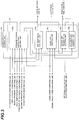
- Fig. 3 is a diagram that shows an outline of processing functions of the engine control unit 50.
- the engine control unit 50 has functions of a pressure sensor correction control unit 50a, a DPF monitoring control unit 50b, an engine speed control unit 50c, a manual DPF regeneration control unit 50d, and an automatic DPF regeneration control unit 50e.
- the pressure sensor correction control unit 50a receives the discrimination results sent from the key switch state discriminating unit 30, the computing results sent from the first pressure computing unit 31, the second pressure computing unit 32, the first temperature computing unit 33, the second temperature computing unit 34, and the temperature computing unit 40, and the discrimination results sent from the sensor error discriminating unit 41. After that, the pressure sensor correction control unit 50a conducts a required computing process and outputs control signals to the correction data storage unit 42, the communications unit 43, the engine speed control unit 50c, and the automatic DPF regeneration control unit 50e.
- the DPF monitoring control unit 50b receives the computing results of the first pressure computing unit 31 and the second pressure computing unit 32 and the correction data that has been stored into the correction data storage unit 42, and outputs control signals to the communications unit 43 and the manual DPF regeneration control unit 50d.
- the engine speed control unit 50c receives the discrimination results of the key switch state discriminating unit 30, the computing results sent from the engine speed computing unit 35 and the engine target speed computing unit 36, and the control signals sent from the pressure sensor correction control unit 50a and the manual DPF regeneration control unit 50d, and outputs a control signal to the electronic governor 2a.
- the manual DPF regeneration control unit 50d receives the control signal sent from the DPF monitoring control unit 50b, and the discrimination results sent from the DPF regenerating switch state discriminating unit 37, conducts a required computing process, and outputs control signals to the engine speed control unit 50c and the regenerating fuel injector 7 in order to conduct the regeneration control (described later herein) of the DPF 4.
- the automatic DPF regeneration control unit 50e receives a control signal from the pressure sensor correction control unit 50a and in response to this control signal, outputs control signals to the engine speed control unit 50c and the regenerating fuel injector 7 in order to conduct the regeneration control of the DPF 4, as with the manual DPF regeneration control unit 50d.
- Fig. 4 is a flowchart that shows details of the computing process by the pressure sensor correction control unit 50a.
- the pressure sensor correction control unit 50a conducts the computing process shown in Fig. 4 . This process is conducted as a preparatory process for starting the engine 2. First, whether the sensors are normal is discriminated from the discrimination results of the sensor error discriminating unit 41 (step S100). If "Yes" is obtained as a result of the discrimination, whether the engine 2 is in a stopped state is discriminated from the computing results of the engine speed computing unit 35 (step S102).
- step S104 whether the differential temperature across the DPF 4 is within a definite range (e.g., 0°C to 3°C) is discriminated from the computing results of the differential temperature computing unit 40 (step S104). Additionally, whether the temperatures at the upstream and downstream sides of the DPF 4 are both within an achievable correction range (e.g., 10°C to 30°C) is discriminated from the computing results of the first and second temperature computing units 33 and 34 (step S106). If all discrimination results are "Yes", correction values ⁇ P1 and ⁇ p2 for correcting the pressures detected by the first and second pressure sensors 21 and 22 are calculated in steps S108 and S110, respectively.
- a definite range e.g., 0°C to 3°C
- the reference output values Pref of the first and second pressure sensors 21, 22 are design data for the values output from the first and second pressure sensors 21, 22 when the internal pressure of the exhaust pipe 3 is the same as an ambient atmospheric pressure.
- the first and second pressure sensors 21, 22 detect the to-be-measured pressures relative to the atmospheric pressure.
- the to-be-measured pressures existing when equal to the atmospheric pressure are detected as relative pressures P1, P2, and any differences of these values with respect to the design data (usually, 0) are calculated as the correction values ⁇ P1, ⁇ P2.
- step S112 whether the two correction values, ⁇ P1 and ⁇ P2, are within predetermined correction ranges is discriminated in step S112. If "Yes” is obtained as discrimination results, the correction values ⁇ P1, ⁇ P2 are stored into the correction data storage unit 42 (step S114) and then a normal engine-control sequence is conducted (step S120). Whether the correction values ⁇ P1, ⁇ P2 are within the correction ranges means whether the values are within tolerances with respect to the design data (i.e., error ranges allowable in terms of design).
- step S118 the discrimination results obtained in at least one of four steps (S102, S104, S106, S112) are "No"
- step S100 the discrimination results obtained in step S100 are "No”
- step S116 and S118 the discrimination results obtained in step S116 are issued in steps S116 and S118, followed by the execution of the normal engine-control sequence in step S120.
- a sensor error warning signal is output as a control signal to the automatic DPF regeneration control unit 50e.
- the sensor error warning signal is also transmitted to the monitor controller 9 via the communications unit 43 and the vehicle body network 12, and the monitor controller 9 displays a sensor error warning on the display unit 10 on the basis of the warning signal.
- an out-of-range warning signal is output to the monitor controller 9 via the communications unit 43 and the vehicle body network 12, and the monitor controller 9 displays an out-of-range warning on the display unit 10 on the basis of the out-of-range warning signal.
- Fig. 5 is a flowchart that shows details of the computing process by the DPF monitoring control unit 50b.
- the DPF monitoring control unit 50b first receives the detection values P1, P2 from the first and second pressure sensors 21, 22 (step S200) and then computes correction pressures P11 and P22 by conducting the following arithmetic operations using the detection values P1, P2 and the correction values ⁇ P1, ⁇ P2 read out from the correction data storage unit 42 (step S202):
- Correction pressure P 11 P 1 ⁇ ⁇ P 1
- Correction pressure P 22 P 2 ⁇ ⁇ P 2
- the correction pressure P22 is subtracted from the correction pressure P11 to calculate the differential pressure P12 across the DPF 4 (step S204).
- step S206 whether the differential pressure P12 is higher than a predetermined first reference differential pressure Pc is discriminated (step S206), and if discrimination results are "Yes", a manual DPF regeneration warning that prompts the operator to start manual regeneration control is displayed on the display unit 10 (step S208). Also, the differential pressure P12 is output to the manual DPF regeneration control unit 50 (step S210). This completes the computing process. Conversely to the above, if the discrimination results obtained in step S206 are "No", the differential pressure P12 is only output to the manual DPF regeneration control unit 50 (step S210). This completes the computing process.
- the DPF monitoring control unit 50b conducts the computing process of Fig. 5 at fixed periods (say, 0.1 second).
- Fig. 6 is a flowchart that shows details of the computing process by the manual DPF regeneration control unit 50d.
- the manual DPF regeneration control unit 50d first discriminates in step S300 whether the DPF regenerating switch 27 is in a turn-on state. If discrimination results are "No", the control unit 50d repeats the process, or if the discrimination results are "Yes”, discriminates in step S302 whether the differential pressure P12 across the DPF 4, output from the DPF monitoring control unit 50b in step S210 of Fig. 5 , is higher than the first reference differential pressure Pc. If discrimination results on P12 are "Yes", the control unit 50d conducts DPF regeneration control in step S304.
- control unit 50d discriminates in step S306 whether the differential pressure P12 is higher than a second reference differential pressure Pc2. If discrimination results are "Yes”, the control unit 50d repeats steps S304 and S306. If "No” is obtained as a result of the discrimination in step S306, the control unit 50d terminates DPF regeneration control and conducts normal engine control in step S308. This also applies if "No” is obtained as a result of the discrimination in step S302. The control of DPF regeneration is conducted to forcibly increase a temperature of the exhaust gases and burn off the PM that has been trapped by the filter 4b.
- the engine speed is maintained at a required level (e.g., 1,800 rpm), then the exhaust gas temperature is increased, and an unburnt fuel is injected under this state from the regenerating fuel injector 7 into the exhaust pipe 3.
- a required level e.g. 1,800 rpm
- the unburnt fuel is burnt with the aid of the oxidizing catalyst 4a within the DPF 4, and the filter-trapped PM is removed using the combustion heat.
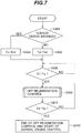
- Fig. 7 is a flowchart that shows details of the computing process by the automatic DPF regeneration control unit 50e.
- step S406 If “No” is obtained as a result of the discrimination, the discrimination in step S406 is conducted again. If the discrimination results in step S406 are "Yes”, the control unit 50e starts DPF regeneration control in step S408 and discriminates in step S410 whether an elapsed time from the start of DPF regeneration control has exceeded a preassigned time Tb. If "No” is obtained as a result of the discrimination, DPF regeneration control in step S408 is conducted again and the discrimination in step S410 is repeated. If the discrimination results in step S410 are "Yes", DPF regeneration control is completed and normal engine control is conducted in step S412.
- the pressure sensor correction control unit 50a of the engine control unit 50 forms a correction data computing element by which, with each start of the engine 2 by turn-on operations of the key switch 20, the differences of the pressures detected by the first and second pressure sensors 21, 22, with respect to the predetermined reference values, are computed as first and second correction values before the engine 2 is started, and the correction data storage unit 42 forms a correction data storage element for storage of the first and second correction values computed by the correction data computing element (the pressure sensor correction control unit 50a).
- the DPF monitoring control unit 50b forms a differential pressure computing element for computing the differential pressure across the filter on the basis of the pressures detected by the first and second pressure sensors, and the differential pressure computing element computes the differential pressure across the filter by using the pressure detection results of the first and second pressure sensors and the first and second correction values stored in the correction data storage element.
- a change of the key switch 20 from the OFF position to the ON position by the operator causes the key switch state discriminating unit 30 to discriminate the turn-on state of the key switch 20 and results of the discrimination to be input to the pressure sensor correction control unit 50a of the engine control unit 50.
- the sensor correction control unit 50a conducts the starting process for the engine 2 and starts the computing process shown in Fig. 4 .
- control unit 50a first discriminates whether the sensors 21 to 25 are all normal, whether the engine 2 is in a stopped state, whether the exhaust gas temperatures at the upstream and downstream sides of the DPF 4, within the exhaust pipe 3, are within a predetermined range, and whether the difference between the exhaust gas temperatures at the upstream and downstream sides of the DPF 4, within the exhaust pipe 3, is within a predetermined range. If all discrimination results are "Yes", the correction values ⁇ P1 and ⁇ P2 of the first and second pressure sensors 21 and 22 are calculated in steps S100, S102, S104, and S106, in that order, of Fig. 4 .
- the correction values are stored into the correction data storage unit 42 in steps S112 and S114 of Fig. 4 and then normal starting control for the engine 2 is conducted in step S120 of Fig. 4 .
- the out-of-range warning is displayed on the display unit 10 in step S118 and normal engine control is conducted in step S120.
- the sensor error warning is displayed on the display unit 10 and the sensor error warning control signal is output to the automatic regeneration control unit (not shown) for the DPF 4. This is followed by engine starting control (steps S116, S118, and S120 of Fig. 4 ).
- the correction values ⁇ P1, ⁇ P2 of the pressure sensors 21, 22 arranged at the upstream and downstream sides of the DPF 4 are calculated and then the calculated correction values are used to correct the pressures P1, P2 detected by the pressure sensors 21, 22. More accurate values P11, P22 are therefore obtainable as pressure detection results.
- the correction values ⁇ P1, ⁇ P2 of the first and second pressure sensors 21, 22 are calculated, only if a differential temperature between the upstream and downstream sides of the DPF 4 is within a predefined range. Since the pressure sensors 21, 22 have temperature dependence, the pressures P1, P2 detected by the sensors will change according to temperature, so the correction values ⁇ P1, ⁇ P2 calculated using the sensor-detected pressure data will also be affected by the temperature. More accurate values P11, P22 can therefore be obtained as pressure detection results by calculating the correction values ⁇ P1, ⁇ P2, only when the differential temperature across the DPF 4 is within the predefined range (i.e., only under equal temperature conditions).
- the differential pressure P12 across the DPF 4 is computed and monitored by the DPF monitoring control unit 50b.
- the DPF monitoring control unit 50b reads out from the correction data storage unit 42 the correction values ⁇ P1, ⁇ P2 of the pressure sensors 21, 22 that have been computed during the engine start, and after using these computed correction values ⁇ P1, ⁇ P2 to correct the sensor-detected pressures P1, P2 and calculate the pressures P11, P22, uses the calculated pressures P11, P22 to calculate the differential pressure P12 across the DPF 4 (steps S200-S204 of Fig. 5 ).
- the detected pressures P1, P2 are corrected using the correction values ⁇ P1, ⁇ P2 and then the differential pressure P12 across the DPF 4 is calculated using the corrected pressures P11, P22, so the differential pressure across the DPF 4 can be measured accurately.
- the thus-obtained differential pressure P12 is compared with the first reference differential pressure Pc. If the differential pressure P12 is lower than the first reference differential pressure Pc, no processing occurs, or if the differential pressure P12 is higher than the first reference differential pressure Pc, the amount of PM deposited in the DPF 4 is regarded as exceeding a predefined level. In this latter case, the display unit 10 displays the manual regeneration warning to prompt the operator to start manual regeneration (steps S206 and S208 of Fig. 5 ). The process of steps S200 to S210 is executed periodically, for example, at fixed intervals of 0.1 second.
- automatic DPF regeneration control by the automatic DPF regeneration control unit 50e is conducted concurrently with the above-described DPF monitoring control by the DPF monitoring control unit 50b.
- the regeneration of the DPF 4 is controlled periodically (e.g., every three hours) by the automatic DPF regeneration control unit 50e, regardless of the amount of PM deposited or other conditions.
- an execution time interval of DPF regeneration control is shortened to two hours, for example, and the regeneration of the DPF 4 is controlled at this time interval.
- the operator controls the manual regeneration control unit 50d by pressing the DPF manual regenerating switch 27 to control the regeneration of the DPF 4.
- a press of the DPF manual regenerating switch 27 by the operator starts DPF regeneration control, which is then continued until the differential pressure P12 across the DPF 4 has decreased below the predetermined second reference differential pressure Pc2 at which the PM deposited in the DPF 4 is judged to have been removed. After confirmation of the decrease in the differential pressure, DPF regeneration control is completed (steps S300 to S310 of Fig. 6 ).
- a press of the DPF manual regenerating switch 27 by the operator without the manual regeneration warning being displayed on the display unit 10 does not start DPF regeneration control (steps S302 to S308 of Fig. 6 ).
- the manual regeneration warning lets the operator know that it has become necessary to regenerate the DPF 4, and allows the operator to start manual DPF regeneration. Decreases in PM-trapping capability, caused by clogging due to PM deposition, therefore, can be suppressed. In addition, a delay in the regeneration of the DPF 4 against the deposition level of the PM can be avoided, and hence, thermal damage to the DPF 4 due to rapid PM burning can be avoided.
- the pressures P1, P2 that have been detected by the pressure sensors 21, 22 provided at the upstream side and downstream side, respectively, of the DPF 4 are corrected using the first and second correction values that have been computed by the pressure sensor correction control unit 50a and stored into the correction data storage unit 42, and the differential pressure across the DPF 4 is calculated from the corrected pressures P11, P22, so the differential pressure across the DPF 4 can be measured accurately, even during the use of two pressure sensors (the first and second pressure sensors).
- the first and second pressure sensors 21, 22 can be ordinary pressure sensors, the sensors can be simplified in structure and improved in durability, compared with a differential pressure sensor.
- the first correction value ⁇ P1 and the second correction value ⁇ P2 are calculated only when a difference in ambient temperature between the pressure sensors 21, 22 at the upstream and downstream sides of the DPF 4 is within a predefined data range, relative errors in the correction values ⁇ P1, ⁇ P2 due to the difference in ambient temperature between the pressure sensors 21, 22 can be suppressed and thus the differential pressure across the DPF 4 can be measured more accurately.
- first correction value ⁇ P1 and the second correction value ⁇ P2 are calculated only when the ambient temperatures of the pressure sensors 21, 22 provided at the upstream and downstream sides of the DPF 4 are within predefined respective data ranges, relative errors in the correction values ⁇ P1, ⁇ P2 can be suppressed and thus the differential pressure across the DPF 4 can be measured more accurately.
- the automatic DPF regeneration control unit 50e regenerates the DPF 4 periodically and since the control unit 50e shortens the automatic regeneration time interval in the event of a failure in at least one of the first and second pressure sensors 21, 22, filter clogging can be reliably prevented, even if the failures make the pressure sensors 21, 22 unable to detect the pressures at the upstream or downstream sides of the filter.
Landscapes
- Engineering & Computer Science (AREA)
- Chemical & Material Sciences (AREA)
- Combustion & Propulsion (AREA)
- Mechanical Engineering (AREA)
- General Engineering & Computer Science (AREA)
- Chemical Kinetics & Catalysis (AREA)
- Materials Engineering (AREA)
- Health & Medical Sciences (AREA)
- Toxicology (AREA)
- Processes For Solid Components From Exhaust (AREA)
- Filtering Of Dispersed Particles In Gases (AREA)
- Exhaust Gas Treatment By Means Of Catalyst (AREA)
- Exhaust Gas After Treatment (AREA)
Description
- The present invention relates generally to cleaning systems for exhaust gas emissions from diesel engines mounted in construction machines. More particularly, the invention concerns a diesel engine exhaust gas cleaning system adapted for computing a differential pressure across a filter and using this computed differential pressure to judge whether any particulate matter deposited in the filter is to be removed by burning-off to regenerate the filter.
- Regulations on the exhaust gases emitted from internal combustion engines such as a diesel engine have been tightened each year. In response to the tightening of these regulations, exhaust gas filters and the technology relating to the catalysts used with the filters are also making rapid progress. For example, techniques for reducing the particulate matter (PM) included in diesel engine exhaust gases have already been developed, including the use of a diesel particulate filter (DPF).
- The DPF traps the PM included in the exhaust gases emitted from a diesel engine, and thus reduces the amount of PM emitted into the atmosphere. The DPF burns and removes trapped PM deposits to recover (regenerate) the PM-trapping ability of the filter. Usually, the PM deposited in the DPF is exposed to exhaust gases of a temperature higher than a fixed level and removed by burning (this process is referred to as natural regeneration of the filter). However, when the load upon the diesel engine is light, since the temperature of the exhaust gases does not reach the high temperature level required for the combustion of the PM, the natural regeneration of the DPF does not occur and if this DPF state remains unimproved, excessive PM deposition will clog the DPF.
- To prevent this situation, it is necessary, for example, to burn and remove the trapped PM by forcibly increasing the temperature of the exhaust gases at fixed time intervals, or to calculate the clogging level from the differential pressure across the DPF and if the calculated clogging level exceeds a predetermined level, forcibly burn and remove the PM.
- Patent Document 1, for example, describes a technique for detecting a differential pressure across a DPF by supplying pressures from the upstream and downstream sides of the DPF through pressure-introducing lines to one differential pressure sensor and detecting the differential pressure across the DPF.
Patent Document 2 describes a technique for detecting a differential pressure across a DPF by detecting pressures by means of pressure sensors provided at the upstream and downstream sides of the DPF, and taking the difference. - The document
US 4574589 A discloses a filter or trap disposed in the exhaust passage of a diesel engines in order to trap any particulate matter included in exhaust gases, and a filter unclogging device or burner disposed in the exhaust passage at a point upstream of the filter or trap. - Patent Document 1:
JP, A 2005-344619 - Patent Document 2:
JP, A 7-317529 - Too much of a delay in the regeneration timing of the DPF behind the deposition state of PM causes thermal damage to the DPF due to rapid burning of the deposited PM. Conversely, too much of an advance in the regeneration timing deteriorates fuel efficiency. In both cases, therefore, the differential pressure across the DPF, used for computing the deposition level of PM, requires accurate detection. Using a differential pressure sensor to detect the differential pressure across a DPF, as in Patent Document 1, is disadvantageous in that, compared with an ordinary pressure sensor, the differential pressure sensor is expensive because of its complex structure, and in that the latter is relatively low in durability. In addition, using two pressure sensors, as with the technique described in
Patent Document 2, makes accurate measurement of the differential pressure difficult since variations in quality characteristics between the sensors cause pressure detection accuracy errors to occur within a tolerance range. - An object of the present invention is to provide a diesel engine exhaust gas cleaning system that can measure a differential pressure across a filter accurately by using simply constructed and highly durable sensors during detection of the differential pressure across the filter. Means for Solving the Problems
- (1) In order to attain the above object, in an aspect of the present invention, there is provided an exhaust gas cleaning system for a diesel engine, comprising:
- a filter disposed in an exhaust system of the diesel engine in order to trap any particulate matter included in exhaust gases;
- first and second pressure sensors disposed at upstream and downstream sides, respectively, of the filter; and
- differential pressure computing means for computing, on the basis of pressures detected by the first and second pressure sensors, a differential pressure existing across the filter, the differential pressure across the filter computed by the differential pressure computing means being used for the system to judge whether the filter needs to be regenerated by burning off the particulate matter deposited therein;
correction data storage means into which the first and second correction values computed by the correction data computing means are stored; and
the differential pressure computing means is adapted to use, in addition to the pressure detection results of the first and second pressure sensors, the first and second correction values stored in the correction data storage means, to compute the differential pressure across the filter.
In this way, the differential pressure computing means uses the correction data computing means and the correction data storage means to compute the differences between the pressure detection results of the first and second pressure sensors and the predetermined reference value, as the first and second correction values, with each start of the diesel engine and store the first and second correction values. After this, the differential pressure computing means computes the differential pressure across the filter by using the pressure detection results of the first and second pressure sensors and the stored first and second correction values. Errors in the sensor-detected pressure data due to variations in quality characteristics between the sensors are thus corrected for, so the differential pressure across the filter can be measured accurately, even when two pressure sensors are used, as in the above aspect of the present invention that uses the first and second pressure sensors. In addition, since the first and second pressure sensors can be ordinary pressure sensors, the sensors can be simplified in structure and improved in durability, compared with a differential pressure sensor. - (2) In above item (1), the system further includes a first temperature sensor emplaced at the upstream side of the filter, and a second temperature sensor emplaced at the downstream side of the filter, and only when a difference between temperatures detected by the first and second temperature sensors stays within respective defined data ranges, does the correction data computing means calculate the correction values and store the calculated values into the storage means.
Since the pressure sensors have temperature dependence, changes in temperature change the sensor-detected pressure data (sensor-output data), even when the pressure to be measured remains the same, such that the desired correction values based upon the detected pressure data also change.
In the present invention, more accurate measurement of the differential pressure across the filter is possible since the correction values can be calculated by detecting pressures under equal temperature conditions between the pressure sensors provided at the upstream and downstream sides of the filter. - (3) In above item (1), preferably the system further includes a first temperature sensor emplaced at the upstream side of the filter, and a second temperature sensor emplaced at the downstream side of the filter, and only when temperatures detected by the first and second temperature sensors stay within respective defined data ranges, does the correction data computing means calculate the correction values and store the calculated values into the storage means.
Thus, the correction values can be calculated by detecting pressures under equal temperature conditions between the pressure sensors provided at the upstream and downstream sides of the filter, and hence, the differential pressure across the filter can be measured more accurately. - (4) In above item (1), preferably the system further includes: display means which makes a display that prompts a start of the filter regeneration by the burning-off of the particulate matter deposited therein, when the differential pressure across the filter computed by the differential pressure computing means is higher than a required value; and manual regenerating means having a regeneration control switch, the manual regenerating means adapted to start the regeneration of the filter upon activation of the regeneration control switch.
Thus, an operator can obtain information on the particulate matter deposition state of the filter and perform the filter-regenerating process using the information. - (5) In above item (1), preferably the system further includes automatic regenerating means for conducting the regenerating process periodically by burning off the particulate matter deposited in the filter, and is constructed such that if a failure occurs in at least either the first or second pressure sensor, the correction data computing means skips the computation of the first and second correction values and the automatic regenerating means shortens execution time intervals of the regenerating process.
- Thus, even if the pressure sensor failure does not allow pressure detection at the upstream and downstream sides of the filter, filter clogging can be reliably prevented since the filter-regenerating process is conducted at shorter time intervals automatically.
- According to the present invention, a differential pressure across a filter can be measured accurately by using simply constructed and highly durable sensors during the detection of the differential pressure across the filter.
-
-
Fig. 1 is a diagram showing a system for cleaning exhaust gas emissions from an engineering vehicle engine according to an embodiment of the present invention, the diagram also showing an engine control system; -
Fig. 2 is a functional block diagram that shows details of processing functions of an engine controller; -
Fig. 3 is a diagram that shows an outline of processing functions of an engine control unit; -
Fig. 4 is a flowchart that shows details of a computing process by a pressure sensor correction control unit; -
Fig. 5 is a flowchart that shows details of a computing process by a DPF monitoring control unit; -
Fig. 6 is a flowchart that shows details of a computing process by a manual DPF regeneration control unit; -
Fig. 7 is a flowchart that shows details of the computing process by the manual DPF regeneration control unit. -
- 1
- Engine control system
- 2
- Engine
- 2a
- Electronic governor
- 3
- Exhaust pipe
- 4
- DPF
- 4a
- Oxidizing catalyst
- 4b
- Filter
- 5a, 5b
- Temperature sensor
- 6a, 6b
- Pressure sensor
- 7
- Regenerating fuel injector
- 8
- Engine controller
- 9
- Monitor controller
- 10
- Display unit
- 11
- Vehicle body controller
- 12
- Vehicle body network
- 20
- Key switch
- 21
- First pressure sensor
- 22
- Second pressure sensor
- 23
- First temperature sensor
- 24
- Second temperature sensor
- 25
- Engine speed sensor
- 26
- Engine control dial
- 27
- DPF regenerating switch
- 30
- Key switch state discriminating unit
- 31
- First pressure computing unit
- 32
- Second pressure computing unit
- 33
- First temperature computing unit
- 34
- Second temperature computing unit
- 35
- Engine speed computing unit
- 36
- Engine target speed computing unit
- 37
- DPF regenerating switch state discriminating unit
- 40
- Temperature difference computing unit
- 41
- Sensor error discriminating unit
- 42
- Correction data storage unit
- 43
- Communications unit
- 50
- Engine control unit
- Hereunder, an embodiment of the present invention will be described referring to the accompanying drawings.
-
Fig. 1 is a diagram showing a system for cleaning exhaust gas emissions from an engineering vehicle according to an embodiment of the present invention, the diagram also showing an engine control system. - Referring to
Fig. 1 ,reference numeral 2 denotes a diesel engine 2 (hereinafter, referred to simply as the engine), theengine 2 including anelectronic governor 2a for controlling a speed of theengine 2, and anexhaust pipe 3 for releasing the exhaust gases from theengine 2 to the outside. -
Reference numeral 100 denotes the engine control system, which includes akey switch 20 for assigning a starting instruction to theengine 2, anengine control dial 26 for specifying a target speed for theengine 2, anengine speed sensor 25 for detecting an actual speed of theengine 2, and anengine controller 8 for conducting required computing processes based upon incoming signals from thekey switch 20, theengine control dial 26, and theengine speed sensor 25, and then transmitting control signals as outputs to theelectronic governor 2a. Theengine controller 8 is connected to avehicle body controller 11 that controls operation of the entire engineering vehicle, and exchanges various information with thevehicle body controller 11 via avehicle body network 12. - The
engine control system 100 also has the exhaust gas cleaning system 1 of the present embodiment. The exhaust gas cleaning system 1 equipped midway in theexhaust pipe 3 includes afilter 4b for trapping any particulate matter (hereinafter, referred to simply as PM) included in the exhaust gas emissions from theengine 2, a diesel particulate filter 4 (hereinafter, referred to simply as DPF) positioned at an upstream side of thefilter 4b and having an oxidizingcatalyst 4a, afirst temperature sensor 23 andsecond temperature sensor 24 for detecting internal temperatures of theexhaust pipe 3 at upstream and downstream sides, respectively, of theDPF 4, afirst pressure sensor 21 andsecond pressure sensor 22 for detecting internal pressures of theexhaust pipe 3 at the upstream and downstream sides, respectively, of theDPF 4, and aDPF regenerating switch 27 for specifying regeneration control (described later herein) of theDPF 4. Signals from each sensor and each switch are input to theengine controller 8. Theengine controller 8 uses the signals to conduct a computing process required for the exhaust gas cleaning system 1. The exhaust gas cleaning system 1 also includes adisplay unit 10 and amonitor controller 9 for controlling thedisplay unit 10. Themonitor controller 9 is connected to thevehicle body network 12, and various information (described later herein) that is based upon processing results of theengine controller 8 is sent to themonitor controller 9 and displayed on thedisplay unit 10. The exhaust gas cleaning system 1 further has a regeneratingfuel injector 7 at the upstream side of theDPF 4 to inject an unburnt fuel on the basis of the processing results of theengine controller 8. Thekey switch 20, theengine control dial 26, theDPF regenerating switch 27, and thedisplay unit 10 are arranged in a cabin (not shown) of the engineering vehicle so as to allow easy operations by an operator. -
Fig. 2 is a functional block diagram that shows details of processing functions of theengine controller 8. - The
engine controller 8 has functions of a key switchstate discriminating unit 30, a first pressure sensor outputdata computing unit 31, a second pressure sensor outputdata computing unit 32, a first temperature sensor outputdata computing unit 33, a second temperature sensor outputdata computing unit 34, an enginespeed computing unit 35, an engine targetspeed computing unit 36, a DPF regenerating switchstate discriminating unit 37, a differentialtemperature computing unit 40, a sensorerror discriminating unit 41, a correctiondata storage unit 42, anengine control unit 50, and acommunications unit 43. - The key switch
state discriminating unit 30 and the DPF regenerating switchstate discriminating unit 37 receive switch signals as input signals from thekey switch 20 and theDPF regenerating switch 27, respectively, and transmit respective discrimination results as output signals to theengine control unit 50. - The first
pressure computing unit 31 and the secondpressure computing unit 32 receive input signals from thefirst pressure sensor 21 and thesecond pressure sensor 22, respectively, and transmit associated computing results as a first pressure and a second pressure, respectively, to theengine control unit 50. - The first temperature sensor output
data computing unit 33 and the second temperature sensor outputdata computing unit 34 receive input signals from thefirst temperature sensor 23 and thesecond temperature sensor 24, respectively, and transmit associated computing results as a first temperature and a second temperature, respectively, to the differentialtemperature computing unit 40 and theengine control unit 50. - The engine
speed computing unit 35 receives an input signal from theengine speed sensor 25 and transmits associated computing results (computed engine speed) as an output signal to theengine control unit 50. - The engine target
speed computing unit 36 receives a voltage signal as an input signal from theengine control dial 26 and transmits associated computing results (computed engine target speed) as an output signal to theengine control unit 50. - The sensor
error discriminating unit 41 receives input signals from the firstpressure computing unit 31, the secondpressure computing unit 32, the firsttemperature computing unit 33, the secondtemperature computing unit 34, and the enginespeed computing unit 35, and after using these signals to discriminate any errors in the sensors 21-25, transmits associated discrimination results to theengine control unit 50. - The correction
data storage unit 42 acquires first pressure and second pressure correction data (described later herein) that has been computed by theengine control unit 50. - The
communications unit 43 is connected to themonitor controller 9 and thevehicle body controller 11 via thevehicle body network 12. In addition to transferring information from theengine control unit 50 to themonitor controller 9 and thevehicle body controller 11, thecommunications unit 43 transfers information from themonitor controller 9 and thevehicle body controller 11 to theengine control unit 50. -
Fig. 3 is a diagram that shows an outline of processing functions of theengine control unit 50. Theengine control unit 50 has functions of a pressure sensorcorrection control unit 50a, a DPFmonitoring control unit 50b, an enginespeed control unit 50c, a manual DPFregeneration control unit 50d, and an automatic DPFregeneration control unit 50e. - The pressure sensor
correction control unit 50a receives the discrimination results sent from the key switchstate discriminating unit 30, the computing results sent from the firstpressure computing unit 31, the secondpressure computing unit 32, the firsttemperature computing unit 33, the secondtemperature computing unit 34, and thetemperature computing unit 40, and the discrimination results sent from the sensorerror discriminating unit 41. After that, the pressure sensorcorrection control unit 50a conducts a required computing process and outputs control signals to the correctiondata storage unit 42, thecommunications unit 43, the enginespeed control unit 50c, and the automatic DPFregeneration control unit 50e. The DPFmonitoring control unit 50b receives the computing results of the firstpressure computing unit 31 and the secondpressure computing unit 32 and the correction data that has been stored into the correctiondata storage unit 42, and outputs control signals to thecommunications unit 43 and the manual DPFregeneration control unit 50d. The enginespeed control unit 50c receives the discrimination results of the key switchstate discriminating unit 30, the computing results sent from the enginespeed computing unit 35 and the engine targetspeed computing unit 36, and the control signals sent from the pressure sensorcorrection control unit 50a and the manual DPFregeneration control unit 50d, and outputs a control signal to theelectronic governor 2a. The manual DPFregeneration control unit 50d receives the control signal sent from the DPFmonitoring control unit 50b, and the discrimination results sent from the DPF regenerating switchstate discriminating unit 37, conducts a required computing process, and outputs control signals to the enginespeed control unit 50c and the regeneratingfuel injector 7 in order to conduct the regeneration control (described later herein) of theDPF 4. The automatic DPFregeneration control unit 50e receives a control signal from the pressure sensorcorrection control unit 50a and in response to this control signal, outputs control signals to the enginespeed control unit 50c and the regeneratingfuel injector 7 in order to conduct the regeneration control of theDPF 4, as with the manual DPFregeneration control unit 50d. - The computing processes by the pressure sensor
correction control unit 50a, DPFmonitoring control unit 50b, manual DPFregeneration control unit 50d, and automatic DPFregeneration control unit 50e shown inFig. 3 , are described in detail below using flowcharts ofFigs. 4 to 7 . -
Fig. 4 is a flowchart that shows details of the computing process by the pressure sensorcorrection control unit 50a. Upon a setting position change of thekey switch 20 from an OFF position to an ON position, the pressure sensorcorrection control unit 50a conducts the computing process shown inFig. 4 . This process is conducted as a preparatory process for starting theengine 2. First, whether the sensors are normal is discriminated from the discrimination results of the sensor error discriminating unit 41 (step S100). If "Yes" is obtained as a result of the discrimination, whether theengine 2 is in a stopped state is discriminated from the computing results of the engine speed computing unit 35 (step S102). Also, whether the differential temperature across theDPF 4 is within a definite range (e.g., 0°C to 3°C) is discriminated from the computing results of the differential temperature computing unit 40 (step S104). Additionally, whether the temperatures at the upstream and downstream sides of theDPF 4 are both within an achievable correction range (e.g., 10°C to 30°C) is discriminated from the computing results of the first and secondtemperature computing units 33 and 34 (step S106). If all discrimination results are "Yes", correction values ΔP1 and Δp2 for correcting the pressures detected by the first andsecond pressure sensors second pressure sensors 

second pressure sensors second pressure sensors exhaust pipe 3 is the same as an ambient atmospheric pressure. That is to say, when pressures to be measured are applied from a pressure-introducing compartment to one side of a diaphragm to which is attached a strain gauge to form part of a measuring circuit and an opposite side of the diaphragm is opened for exposure to the atmospheric pressure, the first andsecond pressure sensors - Next, whether the two correction values, ΔP1 and ΔP2, are within predetermined correction ranges is discriminated in step S112. If "Yes" is obtained as discrimination results, the correction values ΔP1, ΔP2 are stored into the correction data storage unit 42 (step S114) and then a normal engine-control sequence is conducted (step S120). Whether the correction values ΔP1, ΔP2 are within the correction ranges means whether the values are within tolerances with respect to the design data (i.e., error ranges allowable in terms of design). In addition, if the discrimination results obtained in at least one of four steps (S102, S104, S106, S112) are "No", an out-of-range warning process is conducted in step S118, followed by the execution of the normal engine-control sequence in step S120. If the discrimination results obtained in step S100 are "No", a sensor error warning process and an out-of-range warning process are issued in steps S116 and S118, followed by the execution of the normal engine-control sequence in step S120.
- During the sensor error warning process shown in step S116, a sensor error warning signal is output as a control signal to the automatic DPF
regeneration control unit 50e. The sensor error warning signal is also transmitted to themonitor controller 9 via thecommunications unit 43 and thevehicle body network 12, and themonitor controller 9 displays a sensor error warning on thedisplay unit 10 on the basis of the warning signal. During the out-of-range warning process shown in step S118, an out-of-range warning signal is output to themonitor controller 9 via thecommunications unit 43 and thevehicle body network 12, and themonitor controller 9 displays an out-of-range warning on thedisplay unit 10 on the basis of the out-of-range warning signal. -
Fig. 5 is a flowchart that shows details of the computing process by the DPFmonitoring control unit 50b. The DPFmonitoring control unit 50b first receives the detection values P1, P2 from the first andsecond pressure sensors 21, 22 (step S200) and then computes correction pressures P11 and P22 by conducting the following arithmetic operations using the detection values P1, P2 and the correction values ΔP1, ΔP2 read out from the correction data storage unit 42 (step S202):

monitoring control unit 50b conducts the computing process ofFig. 5 at fixed periods (say, 0.1 second). -
Fig. 6 is a flowchart that shows details of the computing process by the manual DPFregeneration control unit 50d. The manual DPFregeneration control unit 50d first discriminates in step S300 whether theDPF regenerating switch 27 is in a turn-on state. If discrimination results are "No", thecontrol unit 50d repeats the process, or if the discrimination results are "Yes", discriminates in step S302 whether the differential pressure P12 across theDPF 4, output from the DPFmonitoring control unit 50b in step S210 ofFig. 5 , is higher than the first reference differential pressure Pc. If discrimination results on P12 are "Yes", thecontrol unit 50d conducts DPF regeneration control in step S304. Additionally, thecontrol unit 50d discriminates in step S306 whether the differential pressure P12 is higher than a second reference differential pressure Pc2. If discrimination results are "Yes", thecontrol unit 50d repeats steps S304 and S306. If "No" is obtained as a result of the discrimination in step S306, thecontrol unit 50d terminates DPF regeneration control and conducts normal engine control in step S308. This also applies if "No" is obtained as a result of the discrimination in step S302. The control of DPF regeneration is conducted to forcibly increase a temperature of the exhaust gases and burn off the PM that has been trapped by thefilter 4b. For example, the engine speed is maintained at a required level (e.g., 1,800 rpm), then the exhaust gas temperature is increased, and an unburnt fuel is injected under this state from the regeneratingfuel injector 7 into theexhaust pipe 3. Thus, the unburnt fuel is burnt with the aid of the oxidizingcatalyst 4a within theDPF 4, and the filter-trapped PM is removed using the combustion heat. -
Fig. 7 is a flowchart that shows details of the computing process by the automatic DPFregeneration control unit 50e. The automatic DPFregeneration control unit 50e first discriminates in step S400 whether the sensor error warning signal from the pressure sensorcorrection control unit 50a is on. If "No" is obtained as a result of the discrimination, thecontrol unit 50e assigns a reference time Ta=Ta1 in step S402, or if "Yes" is obtained as a result of the discrimination, thecontrol unit 50e assigns a reference time Ta=Ta2 in step S404. Next, thecontrol unit 50e discriminates in step S406 whether an elapsed time T1 from previous DPF regeneration control is in excess of the reference time Ta. If "No" is obtained as a result of the discrimination, the discrimination in step S406 is conducted again. If the discrimination results in step S406 are "Yes", thecontrol unit 50e starts DPF regeneration control in step S408 and discriminates in step S410 whether an elapsed time from the start of DPF regeneration control has exceeded a preassigned time Tb. If "No" is obtained as a result of the discrimination, DPF regeneration control in step S408 is conducted again and the discrimination in step S410 is repeated. If the discrimination results in step S410 are "Yes", DPF regeneration control is completed and normal engine control is conducted in step S412. - In the above, the pressure sensor
correction control unit 50a of theengine control unit 50 forms a correction data computing element by which, with each start of theengine 2 by turn-on operations of thekey switch 20, the differences of the pressures detected by the first andsecond pressure sensors engine 2 is started, and the correctiondata storage unit 42 forms a correction data storage element for storage of the first and second correction values computed by the correction data computing element (the pressure sensorcorrection control unit 50a). Also, the DPFmonitoring control unit 50b forms a differential pressure computing element for computing the differential pressure across the filter on the basis of the pressures detected by the first and second pressure sensors, and the differential pressure computing element computes the differential pressure across the filter by using the pressure detection results of the first and second pressure sensors and the first and second correction values stored in the correction data storage element. - Operation of the thus-constructed present embodiment is described below.
- A change of the
key switch 20 from the OFF position to the ON position by the operator causes the key switchstate discriminating unit 30 to discriminate the turn-on state of thekey switch 20 and results of the discrimination to be input to the pressure sensorcorrection control unit 50a of theengine control unit 50. Upon receiving the discrimination results, the sensorcorrection control unit 50a conducts the starting process for theengine 2 and starts the computing process shown inFig. 4 . That is to say,control unit 50a first discriminates whether thesensors 21 to 25 are all normal, whether theengine 2 is in a stopped state, whether the exhaust gas temperatures at the upstream and downstream sides of theDPF 4, within theexhaust pipe 3, are within a predetermined range, and whether the difference between the exhaust gas temperatures at the upstream and downstream sides of theDPF 4, within theexhaust pipe 3, is within a predetermined range. If all discrimination results are "Yes", the correction values ΔP1 and ΔP2 of the first andsecond pressure sensors Fig. 4 . After this, if the calculated correction values ΔP1, ΔP2 are within predetermined ranges, the correction values are stored into the correctiondata storage unit 42 in steps S112 and S114 ofFig. 4 and then normal starting control for theengine 2 is conducted in step S120 ofFig. 4 . However, if even one of thesensors 21 to 25 is abnormal, or if the exhaust gas temperatures at the upstream and downstream sides of theDPF 4, within theexhaust pipe 3, are outside the predetermined range, or if the difference between the exhaust gas temperatures at the upstream and downstream sides of theDPF 4, within theexhaust pipe 3, is outside the predetermined range, the out-of-range warning is displayed on thedisplay unit 10 in step S118 and normal engine control is conducted in step S120. Additionally, if any one of the sensors 21-25 is abnormal, the sensor error warning is displayed on thedisplay unit 10 and the sensor error warning control signal is output to the automatic regeneration control unit (not shown) for theDPF 4. This is followed by engine starting control (steps S116, S118, and S120 ofFig. 4 ). - In this manner, the correction values ΔP1, ΔP2 of the
pressure sensors DPF 4 are calculated and then the calculated correction values are used to correct the pressures P1, P2 detected by thepressure sensors - The correction values ΔP1, ΔP2 of the first and
second pressure sensors DPF 4 is within a predefined range. Since thepressure sensors DPF 4 is within the predefined range (i.e., only under equal temperature conditions). - In addition, only when the temperatures of the
pressure sensors DPF 4 meet the predefined temperature conditions, will the pressures P1, P2 be detected and the correction values ΔP1, ΔP2 calculated. More accurate values P11, P22 can therefore be obtained as pressure detection results. - After the engine start, during normal operation, the differential pressure P12 across the
DPF 4 is computed and monitored by the DPFmonitoring control unit 50b. In this case, the DPFmonitoring control unit 50b reads out from the correctiondata storage unit 42 the correction values ΔP1, ΔP2 of thepressure sensors Fig. 5 ). In this way, the detected pressures P1, P2 are corrected using the correction values ΔP1, ΔP2 and then the differential pressure P12 across theDPF 4 is calculated using the corrected pressures P11, P22, so the differential pressure across theDPF 4 can be measured accurately. - The thus-obtained differential pressure P12 is compared with the first reference differential pressure Pc. If the differential pressure P12 is lower than the first reference differential pressure Pc, no processing occurs, or if the differential pressure P12 is higher than the first reference differential pressure Pc, the amount of PM deposited in the
DPF 4 is regarded as exceeding a predefined level. In this latter case, thedisplay unit 10 displays the manual regeneration warning to prompt the operator to start manual regeneration (steps S206 and S208 ofFig. 5 ). The process of steps S200 to S210 is executed periodically, for example, at fixed intervals of 0.1 second. - After the engine start, during normal operation, automatic DPF regeneration control by the automatic DPF
regeneration control unit 50e is conducted concurrently with the above-described DPF monitoring control by the DPFmonitoring control unit 50b. - During normal operation with the sensor error warning control signal off, the regeneration of the
DPF 4 is controlled periodically (e.g., every three hours) by the automatic DPFregeneration control unit 50e, regardless of the amount of PM deposited or other conditions. When the sensor error warning control signal is on, an execution time interval of DPF regeneration control is shortened to two hours, for example, and the regeneration of theDPF 4 is controlled at this time interval. - Decreases in PM-trapping capability, caused by clogging due to PM deposition, can be suppressed, even when the deposition state of PM in the
DPF 4 cannot be accurately detected for reasons such as the above-described sensor error occurring. In addition, a delay in the regeneration of theDPF 4 against the deposition level of the PM can be avoided, and hence, thermal damage to theDPF 4 due to rapid PM burning can be avoided. - After the engine start, if the manual regeneration warning is displayed on the
display unit 10 by the DPFmonitoring control unit 50b, the operator controls the manualregeneration control unit 50d by pressing the DPFmanual regenerating switch 27 to control the regeneration of theDPF 4. - A press of the DPF
manual regenerating switch 27 by the operator starts DPF regeneration control, which is then continued until the differential pressure P12 across theDPF 4 has decreased below the predetermined second reference differential pressure Pc2 at which the PM deposited in theDPF 4 is judged to have been removed. After confirmation of the decrease in the differential pressure, DPF regeneration control is completed (steps S300 to S310 ofFig. 6 ). - A press of the DPF
manual regenerating switch 27 by the operator without the manual regeneration warning being displayed on thedisplay unit 10 does not start DPF regeneration control (steps S302 to S308 ofFig. 6 ). - As can be seen from the above, the manual regeneration warning lets the operator know that it has become necessary to regenerate the
DPF 4, and allows the operator to start manual DPF regeneration. Decreases in PM-trapping capability, caused by clogging due to PM deposition, therefore, can be suppressed. In addition, a delay in the regeneration of theDPF 4 against the deposition level of the PM can be avoided, and hence, thermal damage to theDPF 4 due to rapid PM burning can be avoided. - As described above, according to the present embodiment, the pressures P1, P2 that have been detected by the
pressure sensors DPF 4 are corrected using the first and second correction values that have been computed by the pressure sensorcorrection control unit 50a and stored into the correctiondata storage unit 42, and the differential pressure across theDPF 4 is calculated from the corrected pressures P11, P22, so the differential pressure across theDPF 4 can be measured accurately, even during the use of two pressure sensors (the first and second pressure sensors). In addition, since the first andsecond pressure sensors - Furthermore, since the first correction value ΔP1 and the second correction value ΔP2 are calculated only when a difference in ambient temperature between the
pressure sensors DPF 4 is within a predefined data range, relative errors in the correction values ΔP1, ΔP2 due to the difference in ambient temperature between thepressure sensors DPF 4 can be measured more accurately. - Furthermore, since the first correction value ΔP1 and the second correction value ΔP2 are calculated only when the ambient temperatures of the
pressure sensors DPF 4 are within predefined respective data ranges, relative errors in the correction values ΔP1, ΔP2 can be suppressed and thus the differential pressure across theDPF 4 can be measured more accurately. - Moreover, when the differential pressure P12 across the
DPF 4, measured under the control of the DPFmonitoring control unit 50b, is higher than the predetermined value, that is, when the deposition of PM reaches the level at which the regeneration of theDPF 4 becomes necessary, since the display of the appropriate information on thedisplay unit 10 prompts the operator to start the regeneration process and causes the operator to start manual regeneration of theDPF 4 in accordance with the information, timely regeneration of theDPF 4 can be conducted according to the particular deposition state of the PM. This prevents unnecessary regeneration, hence minimizing fuel consumption. Thermal damage to theDPF 4 due to regeneration under an excessive deposition state of PM can also be avoided. - Besides, since the automatic DPF
regeneration control unit 50e regenerates theDPF 4 periodically and since thecontrol unit 50e shortens the automatic regeneration time interval in the event of a failure in at least one of the first andsecond pressure sensors pressure sensors
Claims (3)
- An exhaust gas cleaning system for a diesel engine (2), comprising:a filter (4) disposed in an exhaust system of the diesel engine (2) in order to trap any particulate matter included in exhaust gases;first and second pressure sensors (21, 22) disposed at upstream and downstream sides, respectively, of said filter; anddifferential pressure computing means (50b) for computing, on the basis of pressures (P1, P2) detected by said first and second pressure sensors (21, 22), a differential pressure (P12) existing across said filter, the differential pressure across said filter computed by said differential pressure computing means being used for the system to judge whether said filter needs to be regenerated by burning off the particulate matter deposited therein;characterized in that said exhaust gas cleaning system includes:a first temperature sensor (23) emplaced at the upstream side of said filter (4); anda second temperature sensor (24) emplaced at the downstream side of said filter (4),wherein when pressure to be measure are applied from a pressure-introducing compartment to one side of a diaphragm to which is attached a strain gauge to from part of a measuring circuit and an opposite side of the diaphragm is opened for exposure to the atmospheric pressure, the first and second pressure sensors detect the to-be-measured pressures relative to the atmospheric pressure,wherein said exhaust gas cleaning system includes:correction data computing means (50b) by which, each time a key switch (20) for starting the diesel engine is turned on and before the diesel engine is started, any differences of the pressures detected by said first and second pressure sensors, with respect to a predetermined reference pressure value (Pref), are computed to obtain first and second correction values (ΔP1, ΔP2); andcorrection data storage means into which the first and second correction values computed by said correction data computing means are stored,wherein said differential pressure computing means (50b) is adapted to use, in addition to the pressure detection results of said first and second pressure sensors, the first and second correction values stored in the correction data storage means, to compute the differential pressure across said filter, andwherein only when a difference between temperatures detected by the first and second temperature sensors is within a defied data range and temperatures detected by the first and second temperature sensors and within respective defined data ranges, does said correction data computing means (50a) calculate the correction values (ΔP1, ΔP2) and store the calculated values into the correction data storage means (42.
- The exhaust gas cleaning system for the diesel engine (2) according to claim 1, further comprising:display means (10) which makes a display that prompts a start of said filter regeneration by the burning-off of the particulate matter deposited therein, when the differential pressure (P12) across said filter (4) computed by said differential pressure computing means (50b) is higher than a required value (Pc); andmanual regenerating means (50d) having a regeneration control switch (27), said manual regenerating means (50d) adapted to start the regeneration of said filter upon activation of the regeneration control switch.
- The exhaust gas cleaning system for the diesel engine (2) according to claim 1, further comprising:automatic regenerating means (50e) for conducting periodically the regeneration of said filter (4) by burning off the particulate matter deposited therein,wherein if a failure occurs in at least one of said first and second pressure sensors (21, 22), said correction data computing means (50a) skips the computation of the first and second correction values (ΔP1, ΔP2); andthe automatic regenerating means shortens an execution time interval of the regeneration.
Applications Claiming Priority (2)
| Application Number | Priority Date | Filing Date | Title |
|---|---|---|---|
| JP2007260998A JP5001778B2 (en) | 2007-10-04 | 2007-10-04 | Diesel engine exhaust gas purification system |
| PCT/JP2008/062959 WO2009044581A1 (en) | 2007-10-04 | 2008-07-17 | Exhaust gas purification system of diesel engine |
Publications (3)
| Publication Number | Publication Date |
|---|---|
| EP2199552A1 EP2199552A1 (en) | 2010-06-23 |
| EP2199552A4 EP2199552A4 (en) | 2015-05-20 |
| EP2199552B1 true EP2199552B1 (en) | 2017-03-01 |
Family
ID=40526011
Family Applications (1)
| Application Number | Title | Priority Date | Filing Date |
|---|---|---|---|
| EP08778251.2A Not-in-force EP2199552B1 (en) | 2007-10-04 | 2008-07-17 | Exhaust gas purification system of diesel engine |
Country Status (6)
| Country | Link |
|---|---|
| US (1) | US8302386B2 (en) |
| EP (1) | EP2199552B1 (en) |
| JP (1) | JP5001778B2 (en) |
| KR (1) | KR101414945B1 (en) |
| CN (1) | CN101568702B (en) |
| WO (1) | WO2009044581A1 (en) |
Families Citing this family (31)
| Publication number | Priority date | Publication date | Assignee | Title |
|---|---|---|---|---|
| JP5101436B2 (en) * | 2008-08-26 | 2012-12-19 | ヤンマー株式会社 | diesel engine |
| US20100212299A1 (en) * | 2009-02-25 | 2010-08-26 | Jacob George | Methods for determining when to regenerate exhaust gas particulate filters |
| JP5135286B2 (en) * | 2009-05-21 | 2013-02-06 | 日立建機株式会社 | Exhaust purification system |
| JP5388743B2 (en) * | 2009-08-07 | 2014-01-15 | 日立建機株式会社 | Display device for work equipment |
| JP5155979B2 (en) | 2009-10-21 | 2013-03-06 | ヤンマー株式会社 | diesel engine |
| JP5271300B2 (en) * | 2010-03-19 | 2013-08-21 | 株式会社小松製作所 | Construction machine display device |
| DE102010043135A1 (en) * | 2010-10-29 | 2012-05-03 | Deere & Company | Hydraulic arrangement |
| US9080494B2 (en) * | 2011-06-07 | 2015-07-14 | GM Global Technology Operations LLC | Particulate filter monitoring methods and systems |
| KR101684496B1 (en) * | 2011-09-09 | 2016-12-09 | 현대자동차 주식회사 | System for purifying exhaust gas and method for controlling the same |
| EP2803832B1 (en) * | 2012-01-13 | 2017-01-04 | Hitachi Construction Machinery Co., Ltd. | Construction machine |
| DE102012203097B3 (en) * | 2012-02-29 | 2013-04-11 | Continental Automotive Gmbh | Method for determining error of pressure measured by pressure sensor in pressure accumulator for storing fluid in automobile, involves determining two three-tuples of pressures and of time period |
| US9109481B2 (en) | 2012-05-24 | 2015-08-18 | Ford Global Technologies, Llc | Method to control and diagnose an exhaust gas heat exchanger |
| US8959904B2 (en) * | 2012-05-24 | 2015-02-24 | Ford Global Technologies, Llc | Method to control and diagnose an exhaust gas heat exchanger |
| IN2014MN02660A (en) | 2012-06-21 | 2015-08-28 | Mack Trucks | |
| JP5907123B2 (en) | 2012-07-13 | 2016-04-20 | 井関農機株式会社 | Soot deposition calculation display device |
| US8966882B2 (en) * | 2012-09-12 | 2015-03-03 | GM Global Technology Operations LLC | Differential pressure-based enablement of a particulate filter diagnostic |
| US10207567B2 (en) * | 2012-10-19 | 2019-02-19 | Ford Global Technologies, Llc | Heater core isolation valve position detection |
| JP2015010478A (en) * | 2013-06-26 | 2015-01-19 | ヤンマー株式会社 | Agricultural work vehicle |
| PT2818658E (en) | 2013-06-27 | 2016-06-09 | Iseki Agricult Mach | Soot deposition calculating display device |
| US20150020504A1 (en) * | 2013-07-19 | 2015-01-22 | International Engine Intellectual Property Company, Llc | Exhaust flow estimation |
| US9074507B2 (en) * | 2013-08-07 | 2015-07-07 | GM Global Technology Operations LLC | Event-based deviation integration temperature control loop diagnostic system |
| US9328639B2 (en) * | 2013-09-10 | 2016-05-03 | GM Global Technology Operations LLC | Regeneration system to regenerate a particulate filter based on code clear diagnostic signal |
| DE102013018978B4 (en) * | 2013-11-14 | 2024-05-23 | Man Truck & Bus Se | Method for simulating the operation of an internal combustion engine and device for carrying out the method |
| JP6319034B2 (en) * | 2014-10-10 | 2018-05-09 | トヨタ自動車株式会社 | Filter inspection device and filter inspection method |
| JP6401811B2 (en) * | 2017-03-15 | 2018-10-10 | Kyb株式会社 | Fluid property detector |
| US11333056B2 (en) * | 2019-07-15 | 2022-05-17 | Fca Us Llc | Gasoline particulate filter brick detection techniques |
| CN115485464B (en) * | 2020-05-27 | 2024-10-29 | 日立安斯泰莫株式会社 | Internal combustion engine control device |
| CN114235271B (en) * | 2021-11-12 | 2024-01-12 | 潍柴动力股份有限公司 | Dew point detection method, device, storage medium and equipment for differential pressure sensor |
| JP7750129B2 (en) * | 2022-02-02 | 2025-10-07 | コベルコ建機株式会社 | Diagnostic device for exhaust gas aftertreatment device, diagnostic method for exhaust gas aftertreatment device, and diagnostic program for exhaust gas aftertreatment device |
| CN115013131B (en) * | 2022-07-26 | 2023-11-17 | 潍柴动力股份有限公司 | DPF state monitoring method and device and vehicle |
| JP2025083629A (en) * | 2023-11-21 | 2025-06-02 | 株式会社豊田自動織機 | Control device and control method |
Family Cites Families (15)
| Publication number | Priority date | Publication date | Assignee | Title |
|---|---|---|---|---|
| JPS59100917U (en) * | 1982-12-24 | 1984-07-07 | 日産自動車株式会社 | Internal combustion engine exhaust particulate treatment device |
| JPH04272419A (en) * | 1991-02-26 | 1992-09-29 | Toyota Motor Corp | Filter regeneration controlling device for internal combustion engine |
| JPH07317529A (en) | 1994-05-20 | 1995-12-05 | Nippondenso Co Ltd | Exhaust emission control device of diesel engine |
| JP2002227631A (en) | 2000-11-29 | 2002-08-14 | Ibiden Co Ltd | Exhaust emission purifying apparatus, method for determining regenerating timing of filter used therefor, program for determining regenerating timing of filter used therefor, and recording medium for storing the program |
| JP2002364439A (en) * | 2001-06-07 | 2002-12-18 | Toyota Motor Corp | Exhaust gas purification device for internal combustion engine |
| JP4244652B2 (en) | 2003-02-13 | 2009-03-25 | 株式会社デンソー | Exhaust gas purification device for internal combustion engine |
| JP2005155444A (en) * | 2003-11-26 | 2005-06-16 | Hino Motors Ltd | Exhaust purification equipment |
| JP3900153B2 (en) | 2003-12-26 | 2007-04-04 | マツダ株式会社 | Engine exhaust purification system |
| JP4341460B2 (en) * | 2004-04-20 | 2009-10-07 | 株式会社デンソー | Exhaust gas purification device for internal combustion engine |
| JP4470593B2 (en) | 2004-06-03 | 2010-06-02 | 株式会社デンソー | Exhaust gas purification device for internal combustion engine |
| JP3824003B2 (en) | 2005-02-24 | 2006-09-20 | いすゞ自動車株式会社 | Exhaust gas purification system |
| US7546762B2 (en) * | 2005-09-01 | 2009-06-16 | International Engine Intellectual Property Company, Llc | Acute angle pressure sensor probe and method |
| JP4534955B2 (en) * | 2005-11-04 | 2010-09-01 | 株式会社デンソー | Exhaust gas purification device for internal combustion engine |
| JP4534969B2 (en) * | 2005-11-25 | 2010-09-01 | 株式会社デンソー | Exhaust purification device for internal combustion engine |
| JP4591389B2 (en) * | 2006-03-16 | 2010-12-01 | 株式会社デンソー | Exhaust purification device for internal combustion engine |
-
2007
- 2007-10-04 JP JP2007260998A patent/JP5001778B2/en not_active Expired - Fee Related
-
2008
- 2008-07-17 CN CN2008800012800A patent/CN101568702B/en not_active Expired - Fee Related
- 2008-07-17 US US12/447,554 patent/US8302386B2/en not_active Expired - Fee Related
- 2008-07-17 KR KR1020097011420A patent/KR101414945B1/en not_active Expired - Fee Related
- 2008-07-17 WO PCT/JP2008/062959 patent/WO2009044581A1/en not_active Ceased
- 2008-07-17 EP EP08778251.2A patent/EP2199552B1/en not_active Not-in-force
Non-Patent Citations (1)
| Title |
|---|
| None * |
Also Published As
| Publication number | Publication date |
|---|---|
| US20100058743A1 (en) | 2010-03-11 |
| JP5001778B2 (en) | 2012-08-15 |
| KR101414945B1 (en) | 2014-07-04 |
| EP2199552A1 (en) | 2010-06-23 |
| JP2009091915A (en) | 2009-04-30 |
| EP2199552A4 (en) | 2015-05-20 |
| WO2009044581A1 (en) | 2009-04-09 |
| CN101568702A (en) | 2009-10-28 |
| KR20100080496A (en) | 2010-07-08 |
| US8302386B2 (en) | 2012-11-06 |
| CN101568702B (en) | 2012-10-24 |
Similar Documents
| Publication | Publication Date | Title |
|---|---|---|
| EP2199552B1 (en) | Exhaust gas purification system of diesel engine | |
| EP2037090B1 (en) | Particulate filter failure detecting system | |
| US8429904B2 (en) | Working machine | |
| US7228223B2 (en) | Method for monitoring an exhaust gas system of a motor vehicle | |
| US8966882B2 (en) | Differential pressure-based enablement of a particulate filter diagnostic | |
| EP1905991A1 (en) | Control method of exhaust gas purification system and exhaust gas purification system | |
| US7558668B2 (en) | Exhaust system having temperature sensor verification | |
| EP0442648B1 (en) | Method of and apparatus for monitoring operation of a catalytic converter | |
| US20160265413A1 (en) | Method and device for monitoring a particulate filter | |
| KR100867479B1 (en) | Signal monitoring method and device | |
| EP2218884A1 (en) | Exhaust gas post-processing device | |
| US20090145111A1 (en) | Problem detection apparatus and method in exhaust purifying apparatus | |
| JP2013002366A (en) | Failure diagnosing device for differential pressure sensor | |
| US7478553B2 (en) | Method for detecting excessive burn | |
| JP4399355B2 (en) | Method for regenerating clogged particulate filter | |
| JP4686431B2 (en) | Air-fuel ratio sensor deterioration diagnosis device | |
| US7824481B2 (en) | System for evaluating the charge state of an exhaust line depollution means | |
| US7051519B2 (en) | Exhaust gas cleaning device for internal combustion engine | |
| EP1582707A1 (en) | Inspection system of particulate filter regeneration system | |
| US7934374B2 (en) | Method and system for combustion engine particulate filter regeneration | |
| EP1323904A1 (en) | Method for detecting uncontrolled regeneration of a particulate filter in an exhaust line of an internal combustion engine | |
| EP1929136B1 (en) | System for regenerating a catalytic particulate filter located in a diesel engine exhaust line | |
| JP2009520152A5 (en) | ||
| JPH0933478A (en) | Oxygen sensor response diagnostic device for internal combustion engine | |
| KR20140080614A (en) | A construction machinary of the dpf have a warning equipment move timing the forced renaturation |
Legal Events
| Date | Code | Title | Description |
|---|---|---|---|
| PUAI | Public reference made under article 153(3) epc to a published international application that has entered the european phase |
Free format text: ORIGINAL CODE: 0009012 |
|
| 17P | Request for examination filed |
Effective date: 20100504 |
|
| AK | Designated contracting states |
Kind code of ref document: A1 Designated state(s): AT BE BG CH CY CZ DE DK EE ES FI FR GB GR HR HU IE IS IT LI LT LU LV MC MT NL NO PL PT RO SE SI SK TR |
|
| AX | Request for extension of the european patent |
Extension state: AL BA MK RS |
|
| DAX | Request for extension of the european patent (deleted) | ||
| REG | Reference to a national code |
Ref country code: DE Ref legal event code: R079 Ref document number: 602008048969 Country of ref document: DE Free format text: PREVIOUS MAIN CLASS: F01N0003020000 Ipc: F01N0003025000 |
|
| RA4 | Supplementary search report drawn up and despatched (corrected) |
Effective date: 20150420 |
|
| RIC1 | Information provided on ipc code assigned before grant |
Ipc: F01N 3/10 20060101ALI20150414BHEP Ipc: F01N 9/00 20060101ALI20150414BHEP Ipc: F01N 3/025 20060101AFI20150414BHEP Ipc: F01N 3/035 20060101ALI20150414BHEP Ipc: B01D 46/42 20060101ALI20150414BHEP Ipc: F01N 13/00 20100101ALI20150414BHEP Ipc: B01D 53/94 20060101ALI20150414BHEP |
|
| GRAP | Despatch of communication of intention to grant a patent |
Free format text: ORIGINAL CODE: EPIDOSNIGR1 |
|
| INTG | Intention to grant announced |
Effective date: 20160928 |
|
| STAA | Information on the status of an ep patent application or granted ep patent |
Free format text: STATUS: GRANT OF PATENT IS INTENDED |
|
| GRAS | Grant fee paid |
Free format text: ORIGINAL CODE: EPIDOSNIGR3 |
|
| GRAA | (expected) grant |
Free format text: ORIGINAL CODE: 0009210 |
|
| STAA | Information on the status of an ep patent application or granted ep patent |
Free format text: STATUS: THE PATENT HAS BEEN GRANTED |
|
| AK | Designated contracting states |
Kind code of ref document: B1 Designated state(s): AT BE BG CH CY CZ DE DK EE ES FI FR GB GR HR HU IE IS IT LI LT LU LV MC MT NL NO PL PT RO SE SI SK TR |
|
| RAP1 | Party data changed (applicant data changed or rights of an application transferred) |
Owner name: HITACHI CONSTRUCTION MACHINERY CO., LTD |
|
| REG | Reference to a national code |
Ref country code: GB Ref legal event code: FG4D |
|
| REG | Reference to a national code |
Ref country code: CH Ref legal event code: EP Ref country code: AT Ref legal event code: REF Ref document number: 871636 Country of ref document: AT Kind code of ref document: T Effective date: 20170315 |
|
| REG | Reference to a national code |
Ref country code: IE Ref legal event code: FG4D |
|
| REG | Reference to a national code |
Ref country code: DE Ref legal event code: R096 Ref document number: 602008048969 Country of ref document: DE |
|
| REG | Reference to a national code |
Ref country code: SE Ref legal event code: TRGR |
|
| REG | Reference to a national code |
Ref country code: NL Ref legal event code: MP Effective date: 20170301 |
|
| REG | Reference to a national code |
Ref country code: LT Ref legal event code: MG4D |
|
| REG | Reference to a national code |
Ref country code: AT Ref legal event code: MK05 Ref document number: 871636 Country of ref document: AT Kind code of ref document: T Effective date: 20170301 |
|
| REG | Reference to a national code |
Ref country code: FR Ref legal event code: PLFP Year of fee payment: 10 |
|
| PG25 | Lapsed in a contracting state [announced via postgrant information from national office to epo] |
Ref country code: LT Free format text: LAPSE BECAUSE OF FAILURE TO SUBMIT A TRANSLATION OF THE DESCRIPTION OR TO PAY THE FEE WITHIN THE PRESCRIBED TIME-LIMIT Effective date: 20170301 Ref country code: GR Free format text: LAPSE BECAUSE OF FAILURE TO SUBMIT A TRANSLATION OF THE DESCRIPTION OR TO PAY THE FEE WITHIN THE PRESCRIBED TIME-LIMIT Effective date: 20170602 Ref country code: HR Free format text: LAPSE BECAUSE OF FAILURE TO SUBMIT A TRANSLATION OF THE DESCRIPTION OR TO PAY THE FEE WITHIN THE PRESCRIBED TIME-LIMIT Effective date: 20170301 Ref country code: FI Free format text: LAPSE BECAUSE OF FAILURE TO SUBMIT A TRANSLATION OF THE DESCRIPTION OR TO PAY THE FEE WITHIN THE PRESCRIBED TIME-LIMIT Effective date: 20170301 Ref country code: NO Free format text: LAPSE BECAUSE OF FAILURE TO SUBMIT A TRANSLATION OF THE DESCRIPTION OR TO PAY THE FEE WITHIN THE PRESCRIBED TIME-LIMIT Effective date: 20170601 |
|
| PG25 | Lapsed in a contracting state [announced via postgrant information from national office to epo] |
Ref country code: LV Free format text: LAPSE BECAUSE OF FAILURE TO SUBMIT A TRANSLATION OF THE DESCRIPTION OR TO PAY THE FEE WITHIN THE PRESCRIBED TIME-LIMIT Effective date: 20170301 Ref country code: BG Free format text: LAPSE BECAUSE OF FAILURE TO SUBMIT A TRANSLATION OF THE DESCRIPTION OR TO PAY THE FEE WITHIN THE PRESCRIBED TIME-LIMIT Effective date: 20170601 Ref country code: ES Free format text: LAPSE BECAUSE OF FAILURE TO SUBMIT A TRANSLATION OF THE DESCRIPTION OR TO PAY THE FEE WITHIN THE PRESCRIBED TIME-LIMIT Effective date: 20170301 Ref country code: AT Free format text: LAPSE BECAUSE OF FAILURE TO SUBMIT A TRANSLATION OF THE DESCRIPTION OR TO PAY THE FEE WITHIN THE PRESCRIBED TIME-LIMIT Effective date: 20170301 |
|
| PG25 | Lapsed in a contracting state [announced via postgrant information from national office to epo] |
Ref country code: NL Free format text: LAPSE BECAUSE OF FAILURE TO SUBMIT A TRANSLATION OF THE DESCRIPTION OR TO PAY THE FEE WITHIN THE PRESCRIBED TIME-LIMIT Effective date: 20170301 |
|
| PG25 | Lapsed in a contracting state [announced via postgrant information from national office to epo] |
Ref country code: EE Free format text: LAPSE BECAUSE OF FAILURE TO SUBMIT A TRANSLATION OF THE DESCRIPTION OR TO PAY THE FEE WITHIN THE PRESCRIBED TIME-LIMIT Effective date: 20170301 Ref country code: RO Free format text: LAPSE BECAUSE OF FAILURE TO SUBMIT A TRANSLATION OF THE DESCRIPTION OR TO PAY THE FEE WITHIN THE PRESCRIBED TIME-LIMIT Effective date: 20170301 Ref country code: CZ Free format text: LAPSE BECAUSE OF FAILURE TO SUBMIT A TRANSLATION OF THE DESCRIPTION OR TO PAY THE FEE WITHIN THE PRESCRIBED TIME-LIMIT Effective date: 20170301 Ref country code: SK Free format text: LAPSE BECAUSE OF FAILURE TO SUBMIT A TRANSLATION OF THE DESCRIPTION OR TO PAY THE FEE WITHIN THE PRESCRIBED TIME-LIMIT Effective date: 20170301 |
|
| PG25 | Lapsed in a contracting state [announced via postgrant information from national office to epo] |
Ref country code: IS Free format text: LAPSE BECAUSE OF FAILURE TO SUBMIT A TRANSLATION OF THE DESCRIPTION OR TO PAY THE FEE WITHIN THE PRESCRIBED TIME-LIMIT Effective date: 20170701 Ref country code: PL Free format text: LAPSE BECAUSE OF FAILURE TO SUBMIT A TRANSLATION OF THE DESCRIPTION OR TO PAY THE FEE WITHIN THE PRESCRIBED TIME-LIMIT Effective date: 20170301 Ref country code: PT Free format text: LAPSE BECAUSE OF FAILURE TO SUBMIT A TRANSLATION OF THE DESCRIPTION OR TO PAY THE FEE WITHIN THE PRESCRIBED TIME-LIMIT Effective date: 20170703 |
|
| REG | Reference to a national code |
Ref country code: DE Ref legal event code: R097 Ref document number: 602008048969 Country of ref document: DE |
|
| PLBE | No opposition filed within time limit |
Free format text: ORIGINAL CODE: 0009261 |
|
| STAA | Information on the status of an ep patent application or granted ep patent |
Free format text: STATUS: NO OPPOSITION FILED WITHIN TIME LIMIT |
|
| PG25 | Lapsed in a contracting state [announced via postgrant information from national office to epo] |
Ref country code: DK Free format text: LAPSE BECAUSE OF FAILURE TO SUBMIT A TRANSLATION OF THE DESCRIPTION OR TO PAY THE FEE WITHIN THE PRESCRIBED TIME-LIMIT Effective date: 20170301 |
|
| 26N | No opposition filed |
Effective date: 20171204 |
|
| PG25 | Lapsed in a contracting state [announced via postgrant information from national office to epo] |
Ref country code: SI Free format text: LAPSE BECAUSE OF FAILURE TO SUBMIT A TRANSLATION OF THE DESCRIPTION OR TO PAY THE FEE WITHIN THE PRESCRIBED TIME-LIMIT Effective date: 20170301 |
|
| REG | Reference to a national code |
Ref country code: CH Ref legal event code: PL |
|
| REG | Reference to a national code |
Ref country code: IE Ref legal event code: MM4A |
|
| PG25 | Lapsed in a contracting state [announced via postgrant information from national office to epo] |
Ref country code: LI Free format text: LAPSE BECAUSE OF NON-PAYMENT OF DUE FEES Effective date: 20170731 Ref country code: CH Free format text: LAPSE BECAUSE OF NON-PAYMENT OF DUE FEES Effective date: 20170731 Ref country code: IE Free format text: LAPSE BECAUSE OF NON-PAYMENT OF DUE FEES Effective date: 20170717 |
|
| REG | Reference to a national code |
Ref country code: BE Ref legal event code: MM Effective date: 20170731 |
|
| REG | Reference to a national code |
Ref country code: FR Ref legal event code: PLFP Year of fee payment: 11 |
|
| PG25 | Lapsed in a contracting state [announced via postgrant information from national office to epo] |
Ref country code: LU Free format text: LAPSE BECAUSE OF NON-PAYMENT OF DUE FEES Effective date: 20170717 |
|
| PG25 | Lapsed in a contracting state [announced via postgrant information from national office to epo] |
Ref country code: BE Free format text: LAPSE BECAUSE OF NON-PAYMENT OF DUE FEES Effective date: 20170731 |
|
| PGFP | Annual fee paid to national office [announced via postgrant information from national office to epo] |
Ref country code: FR Payment date: 20180612 Year of fee payment: 11 |
|
| PG25 | Lapsed in a contracting state [announced via postgrant information from national office to epo] |
Ref country code: MT Free format text: LAPSE BECAUSE OF NON-PAYMENT OF DUE FEES Effective date: 20170717 |
|
| PGFP | Annual fee paid to national office [announced via postgrant information from national office to epo] |
Ref country code: IT Payment date: 20180713 Year of fee payment: 11 Ref country code: DE Payment date: 20180703 Year of fee payment: 11 |
|
| PGFP | Annual fee paid to national office [announced via postgrant information from national office to epo] |
Ref country code: SE Payment date: 20180710 Year of fee payment: 11 Ref country code: GB Payment date: 20180711 Year of fee payment: 11 |
|
| PG25 | Lapsed in a contracting state [announced via postgrant information from national office to epo] |
Ref country code: HU Free format text: LAPSE BECAUSE OF FAILURE TO SUBMIT A TRANSLATION OF THE DESCRIPTION OR TO PAY THE FEE WITHIN THE PRESCRIBED TIME-LIMIT; INVALID AB INITIO Effective date: 20080717 Ref country code: MC Free format text: LAPSE BECAUSE OF FAILURE TO SUBMIT A TRANSLATION OF THE DESCRIPTION OR TO PAY THE FEE WITHIN THE PRESCRIBED TIME-LIMIT Effective date: 20170301 |
|
| PG25 | Lapsed in a contracting state [announced via postgrant information from national office to epo] |
Ref country code: CY Free format text: LAPSE BECAUSE OF NON-PAYMENT OF DUE FEES Effective date: 20170301 |
|
| REG | Reference to a national code |
Ref country code: DE Ref legal event code: R119 Ref document number: 602008048969 Country of ref document: DE |
|
| REG | Reference to a national code |
Ref country code: SE Ref legal event code: EUG |
|
| GBPC | Gb: european patent ceased through non-payment of renewal fee |
Effective date: 20190717 |
|
| PG25 | Lapsed in a contracting state [announced via postgrant information from national office to epo] |
Ref country code: TR Free format text: LAPSE BECAUSE OF FAILURE TO SUBMIT A TRANSLATION OF THE DESCRIPTION OR TO PAY THE FEE WITHIN THE PRESCRIBED TIME-LIMIT Effective date: 20170301 |
|
| PG25 | Lapsed in a contracting state [announced via postgrant information from national office to epo] |
Ref country code: SE Free format text: LAPSE BECAUSE OF NON-PAYMENT OF DUE FEES Effective date: 20190718 Ref country code: GB Free format text: LAPSE BECAUSE OF NON-PAYMENT OF DUE FEES Effective date: 20190717 Ref country code: DE Free format text: LAPSE BECAUSE OF NON-PAYMENT OF DUE FEES Effective date: 20200201 |
|
| PG25 | Lapsed in a contracting state [announced via postgrant information from national office to epo] |
Ref country code: FR Free format text: LAPSE BECAUSE OF NON-PAYMENT OF DUE FEES Effective date: 20190731 |
|
| PG25 | Lapsed in a contracting state [announced via postgrant information from national office to epo] |
Ref country code: IT Free format text: LAPSE BECAUSE OF NON-PAYMENT OF DUE FEES Effective date: 20190717 |