EP2199529A2 - Schirmanordnung - Google Patents
Schirmanordnung Download PDFInfo
- Publication number
- EP2199529A2 EP2199529A2 EP09015468A EP09015468A EP2199529A2 EP 2199529 A2 EP2199529 A2 EP 2199529A2 EP 09015468 A EP09015468 A EP 09015468A EP 09015468 A EP09015468 A EP 09015468A EP 2199529 A2 EP2199529 A2 EP 2199529A2
- Authority
- EP
- European Patent Office
- Prior art keywords
- handle
- screen
- locking
- locking device
- guide tracks
- Prior art date
- Legal status (The legal status is an assumption and is not a legal conclusion. Google has not performed a legal analysis and makes no representation as to the accuracy of the status listed.)
- Granted
Links
Images
Classifications
-
- E—FIXED CONSTRUCTIONS
- E06—DOORS, WINDOWS, SHUTTERS, OR ROLLER BLINDS IN GENERAL; LADDERS
- E06B—FIXED OR MOVABLE CLOSURES FOR OPENINGS IN BUILDINGS, VEHICLES, FENCES OR LIKE ENCLOSURES IN GENERAL, e.g. DOORS, WINDOWS, BLINDS, GATES
- E06B9/00—Screening or protective devices for wall or similar openings, with or without operating or securing mechanisms; Closures of similar construction
- E06B9/24—Screens or other constructions affording protection against light, especially against sunshine; Similar screens for privacy or appearance; Slat blinds
- E06B9/40—Roller blinds
-
- E—FIXED CONSTRUCTIONS
- E06—DOORS, WINDOWS, SHUTTERS, OR ROLLER BLINDS IN GENERAL; LADDERS
- E06B—FIXED OR MOVABLE CLOSURES FOR OPENINGS IN BUILDINGS, VEHICLES, FENCES OR LIKE ENCLOSURES IN GENERAL, e.g. DOORS, WINDOWS, BLINDS, GATES
- E06B9/00—Screening or protective devices for wall or similar openings, with or without operating or securing mechanisms; Closures of similar construction
- E06B9/56—Operating, guiding or securing devices or arrangements for roll-type closures; Spring drums; Tape drums; Counterweighting arrangements therefor
- E06B9/80—Safety measures against dropping or unauthorised opening; Braking or immobilising devices; Devices for limiting unrolling
- E06B9/82—Safety measures against dropping or unauthorised opening; Braking or immobilising devices; Devices for limiting unrolling automatic
Definitions
- This invention relates to screen assembly for a window, and in particular to a self-locking screen assembly for a roof light, that can be reliably locked in any desired position between fully opened and fully closed.
- Windows and in particular roof lights
- screen assemblies fitted to the inside of the frame thereof for selectively obscuring the window.
- Such screen assemblies typically have a spring tensioned roller mounted at an upper side of the frame, around which a suitable screen is wound.
- a free end of the screen is attached to a movable beam or handle which is movably engaged, at its longitudinal ends, in side guide tracks arranged on opposite lateral sides of the screen.
- the ends of the handle are provided with locking devices adapted to engage the guide tracks to lock the screen in any desired position against the restoring force of the tensioned roller.
- the locking devices typically comprise locking members, often in the form of eccentric cams or blocks, mounted to the ends of the handle to be rotatable between a locking position, wherein they engage the guide tracks to prevent movement of the screen, and an unlocked position, wherein the screen is free to move, the locking devices being rotatable to their locking positions under the tension applied by the tensioned roller on the screen and being rotated to their unlocked position by a force applied to the handle against the tension applied by the tensioned roller.
- the locking devices can freely move along the guide track while the handle is being pulled against the tension of the roller and are automatically returned to their locking positions by the tension applied to the screen by the roller once the handle is released.
- a particular difficulty with these known arrangements is that the locking devices are symmetrically duplicated on the relevant opposite lateral sides of these and, as a consequence, have to operate simultaneously. Manufacturing tolerances, wear and flexure in the materials of the handle, guide tracks and the locking devices can interfere with the simultaneous operation of the locking devices. As a result the screen is occasionally only locked on one lateral side of the screen and the screen can jam or become distorted.
- a screen assembly for a window comprising a tensioned screen moveable between a pair of spaced guide tracks, a handle being mounted on a free end of the screen between said guide tracks, and a locking device mounted on each end of the handle, the handle being moveable between a locking position, wherein the locking devices resectively engage a respective one of the guide tracks to prevent movement of the screen, and an unlocked position, wherein the locking devices are free to slide along respective guide tracks such that the screen is free to move with respect to the guide tracks, said handle and associated locking devices being biased towards said locked position by the action of the tensioned screen on the handle and being moveable towards said unlocked position, against said biasing force of the tensioned screen, wherein each locking device is connected to a respective end of the handle by connection means permitting limited movement of the respective locking device with respect to the handle to accommodate misalignment between the locking devices and the guide tracks.
- each respective connection means being adapted to permit limited rotational movement of the respective locking device with respect to the handle between defined stops or abutments.
- the handle is connected to the screen such that the handle and associated locking devices are pivoted towards said locked position under the action of the tensioned screen whereby the locking devices engage the guide tracks to automatically lock the screen in a desired position when the handle is released by a user.
- the screen is attached to the handle at a position offset from and parallel to said rotational axis of the handle such that the tension applied to the handle via the tensioned screen rotates the handle towards its locked position.
- each guide track comprises an elongate rail
- each locking device comprises first and second parts located opposite sides of the rail such that rotation of the locking device brings said first and second parts of the locking device into engagement with either side of the rail to grip the rail.
- each guide track comprises a pair of parallel rails, each locking device being located between the parallel rails of a respective guide track, each locking device having an elliptical or elongated shape having a length greater than the width of the track.
- each locking device comprises a base part mountable on a respective end of the handle and a locking part mounted on the base part for limited rotational movement with respect to the base part about the rotatable axis of the locking devices.
- the locking part of each locking device is provided with a central spindle rotatably receivable within an aperture in the base part, cooperating faces of the locking part and base part being provided with cooperating features which permit limited rotational movement of the locking part with respect to the base part
- such cooperating features may comprise one or more axially projecting arcuate members provided on the base part receivable in one or more corresponding arcuate slots or recesses provided on the locking part, said one or more arcuate slots and said one or more corresponding arcuate members being arranged concentrically with said central spindle and the or each arcuate members having a circumferential extent less than that of the or each corresponding arcuate slots whereby the locking part can rotate with respect to the base part within limits defined by the interaction of the one or more arcuate members and the one or more arcuate slots.
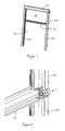
- a screen assembly 10 for a roof light comprises a spring tensioned roller 12 mounted at an upper side of the window frame, around which a suitable screen 14 is wound.
- a free end of the screen 14 is attached to an elongate handle 16 which is movably engaged, at its longitudinal ends, in side guide tracks 20,22 arranged on opposite lateral sides of the screen 14.
- the ends of the handle 16 are provided with locking devices 30,40 adapted to engage the guide tracks 20,22 to lock the screen 14 in any desired position against the restoring force of the tensioned roller 12.
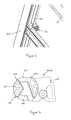
- the locking devices each comprise first and second parts 50,52 located opposite sides of an elongate rail 60 of the respective guide track 20,22 such that rotation of the handle and the asscoiated locking device 30,40 brings said first and second parts 50,52 thereof into engagement with either side of the rail 60 to grip the rail 60.
- the handle and locking devices 30,40 are rotatable about an axis extending transversely to the screen 14 (omitted from Figs. 2 and 3 for clarity) between a locking position, wherein the first and second parts 50,52 of the locking devices 30,40 engage the respective rail 60 of the guide tracks 20,22 tracks to prevent movement of the screen 14, and an unlocked position, wherein the screen 14 is free to move, the handle and locking devices being rotatable to their locking positions under the tension applied by the tensioned roller on the screen and being rotated to their unlocked position by a force applied to the handle against the tension applied by the tensioned roller.
- the handle 16 is provided with an elongate channel 25 for receiving the screen such that the tensioned screen acts on the handle 16 to pivot the handle about a fulcrum defined by the pivot axis of the locking devices 30,40 whereby the tensioned screen 14 pulls on the handle 16 to rotate the handle and locking devices 30,40 towards their respective locking positions.
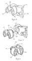
- each locking device 30,40 (which are symmetrically provided on either end of the handle 16 and are mirror images of each other) comprises a base part 100 mountable on a respective end of the handle 16 and a locking part 110 mounted on the base part 100 for limited rotational movement with respect to the base part about the rotatable axis of the locking devices 30,40.
- the locking part 110 of each locking device 30,40 is provided with a central spindle 120 receivable within an aperture 130 in the base part 100.
- the cooperating faces of the locking part 110 and base part 100 are provided with cooperating features which permit limited rotational movement of the locking part 110 with respect to the base part 100.
- such cooperating features comprise a pair of axially projecting arcuate members 140 on the base part receivable in corresponding arcuate slots or recesses 150 provided on the locking part 110, said arcuate slots 150 and corresponding arcuate members 140 being arranged concentrically with said central spindle 120 and the arcuate members 140 having a circumferential extent less than that of the arcuate slots 150 whereby the locking part 100 can rotate with respect to the base part 110 within limits defined by the interaction of the arcuate members 140 and the arcuate slots 150.
- Such difference in circumferential extent may be as little as 1° depending upon the manufacturing and fitting tolerances of the screen assembly, in particular the guide tracks 20,22, and the flexibility of the materials of the screen assembly.
Landscapes
- Engineering & Computer Science (AREA)
- Structural Engineering (AREA)
- Architecture (AREA)
- Civil Engineering (AREA)
- Operating, Guiding And Securing Of Roll- Type Closing Members (AREA)
Applications Claiming Priority (1)
| Application Number | Priority Date | Filing Date | Title |
|---|---|---|---|
| GBGB0822891.8A GB0822891D0 (en) | 2008-12-16 | 2008-12-16 | Screen assembly |
Publications (3)
| Publication Number | Publication Date |
|---|---|
| EP2199529A2 true EP2199529A2 (de) | 2010-06-23 |
| EP2199529A3 EP2199529A3 (de) | 2015-04-15 |
| EP2199529B1 EP2199529B1 (de) | 2017-08-16 |
Family
ID=40326179
Family Applications (1)
| Application Number | Title | Priority Date | Filing Date |
|---|---|---|---|
| EP09015468.3A Active EP2199529B1 (de) | 2008-12-16 | 2009-12-15 | Schirmanordnung |
Country Status (4)
| Country | Link |
|---|---|
| EP (1) | EP2199529B1 (de) |
| DK (1) | DK2199529T3 (de) |
| GB (1) | GB0822891D0 (de) |
| HU (1) | HUE034216T2 (de) |
Cited By (2)
| Publication number | Priority date | Publication date | Assignee | Title |
|---|---|---|---|---|
| WO2012080189A1 (en) | 2010-12-13 | 2012-06-21 | Fourds Limited | Roller blind with installation frame |
| IT201800009260A1 (it) * | 2018-10-08 | 2020-04-08 | Palagina Srl | Tenda con telo avvolgibile ad azionamento manuale |
Family Cites Families (2)
| Publication number | Priority date | Publication date | Assignee | Title |
|---|---|---|---|---|
| DE102006032933A1 (de) * | 2005-07-08 | 2008-02-14 | Happich Fahrzeug- Und Industrieteile Gmbh | Rolloeinrichtung |
| ITBO20070033A1 (it) * | 2007-01-23 | 2008-07-24 | Valla S R L | Congegno automatico di bloccaggio per tenda a caduta verticale con guide. |
-
2008
- 2008-12-16 GB GBGB0822891.8A patent/GB0822891D0/en not_active Ceased
-
2009
- 2009-12-15 DK DK09015468.3T patent/DK2199529T3/en active
- 2009-12-15 EP EP09015468.3A patent/EP2199529B1/de active Active
- 2009-12-15 HU HUE09015468A patent/HUE034216T2/en unknown
Non-Patent Citations (1)
| Title |
|---|
| None |
Cited By (5)
| Publication number | Priority date | Publication date | Assignee | Title |
|---|---|---|---|---|
| WO2012080189A1 (en) | 2010-12-13 | 2012-06-21 | Fourds Limited | Roller blind with installation frame |
| US9247840B2 (en) | 2010-12-13 | 2016-02-02 | Fourds Limited | Roller blind with installation frame |
| AU2011344344B2 (en) * | 2010-12-13 | 2016-08-18 | Fourds Limited | Roller blind with installation frame |
| IT201800009260A1 (it) * | 2018-10-08 | 2020-04-08 | Palagina Srl | Tenda con telo avvolgibile ad azionamento manuale |
| EP3636871A1 (de) | 2018-10-08 | 2020-04-15 | Palagina S.r.l. | Stoffrollo mit manueller betätigung |
Also Published As
| Publication number | Publication date |
|---|---|
| DK2199529T3 (en) | 2017-09-18 |
| HUE034216T2 (en) | 2018-02-28 |
| GB0822891D0 (en) | 2009-01-21 |
| EP2199529B1 (de) | 2017-08-16 |
| EP2199529A3 (de) | 2015-04-15 |
Similar Documents
| Publication | Publication Date | Title |
|---|---|---|
| CN102245054B (zh) | 自动拉入装置和抽拉导向装置 | |
| DE10157754A1 (de) | Vorrichtung zum Öffnen und Schließen eines beweglichen Möbelteils | |
| KR200455185Y1 (ko) | 손잡이 연동식 미닫이문용 열림장치 | |
| AT506543B1 (de) | Feststellvorrichtung zum arretieren eines in oder an einem möbel bewegbar gelagerten möbelteiles | |
| DE10152556C1 (de) | Kraftfahrzeugsitz mit klappbarer Rückenlehne | |
| DE10014499B4 (de) | Rücklehnenschwenkbeschlag für einen Fahrzeugsitz | |
| EP2199529B1 (de) | Schirmanordnung | |
| DK3077609T3 (en) | Sliding door or window fittings and system, door and window comprising the bracket | |
| RU2624195C2 (ru) | Направляющее устройство раздвижной двери для предмета мебели с раздвижными дверями | |
| DE202004004341U1 (de) | Band für eine verdeckte Anordnung zwischen Zarge und Flügel | |
| EP3976912A1 (de) | Nockenanordnung | |
| EP1755519B1 (de) | Standvorrichtung für eine Gehstütze und Gehstütze mit einer Standvorrichtung | |
| CN216240193U (zh) | 风撑装置及使用该风撑装置的窗户 | |
| WO2017155461A1 (en) | Screen system | |
| KR101211761B1 (ko) | 개선된 힌지부를 가지는 프로젝트 및 케이스먼트 운동이가능한 창호 | |
| EP3744935A1 (de) | Nockenanordnung | |
| GB2423787A (en) | Bi-directional bolt-restraint mechanism | |
| GB2547213B (en) | Restrictor assembly | |
| EP0199270A2 (de) | Feststellvorrichtung für einen Fenster- oder Türflügel in wenigstens einer Spaltlüftungsstellung | |
| DE10360039B4 (de) | Vorrichtung zur Schließfolgeregelung für zweiflügelige Drehtüren | |
| DE102012213782B4 (de) | Verlagerungsanordnung zur Verlagerung eines Schiebeflügels eines Fensters, einer Tür oder dergleichen relativ zu einer festen Einfassung mit einem flügelseitigen und einem einfassungsseitigen Steuerelement | |
| JP4693535B2 (ja) | 施錠装置 | |
| DE202005002619U1 (de) | Türantrieb für Drehtüren | |
| DK2499317T3 (en) | Door or window brake device for door or window unit | |
| EP2182149B1 (de) | Anzugseinrichtung für einen Treibstangenbeschlag |
Legal Events
| Date | Code | Title | Description |
|---|---|---|---|
| PUAI | Public reference made under article 153(3) epc to a published international application that has entered the european phase |
Free format text: ORIGINAL CODE: 0009012 |
|
| AK | Designated contracting states |
Kind code of ref document: A2 Designated state(s): AT BE BG CH CY CZ DE DK EE ES FI FR GB GR HR HU IE IS IT LI LT LU LV MC MK MT NL NO PL PT RO SE SI SK SM TR |
|
| AX | Request for extension of the european patent |
Extension state: AL BA RS |
|
| PUAL | Search report despatched |
Free format text: ORIGINAL CODE: 0009013 |
|
| AK | Designated contracting states |
Kind code of ref document: A3 Designated state(s): AT BE BG CH CY CZ DE DK EE ES FI FR GB GR HR HU IE IS IT LI LT LU LV MC MK MT NL NO PL PT RO SE SI SK SM TR |
|
| AX | Request for extension of the european patent |
Extension state: AL BA RS |
|
| RIC1 | Information provided on ipc code assigned before grant |
Ipc: E06B 9/40 20060101AFI20150312BHEP Ipc: E06B 9/82 20060101ALI20150312BHEP Ipc: E06B 9/60 20060101ALI20150312BHEP |
|
| 17P | Request for examination filed |
Effective date: 20150915 |
|
| RBV | Designated contracting states (corrected) |
Designated state(s): AT BE BG CH CY CZ DE DK EE ES FI FR GB GR HR HU IE IS IT LI LT LU LV MC MK MT NL NO PL PT RO SE SI SK SM TR |
|
| GRAP | Despatch of communication of intention to grant a patent |
Free format text: ORIGINAL CODE: EPIDOSNIGR1 |
|
| STAA | Information on the status of an ep patent application or granted ep patent |
Free format text: STATUS: GRANT OF PATENT IS INTENDED |
|
| INTG | Intention to grant announced |
Effective date: 20170317 |
|
| GRAS | Grant fee paid |
Free format text: ORIGINAL CODE: EPIDOSNIGR3 |
|
| GRAA | (expected) grant |
Free format text: ORIGINAL CODE: 0009210 |
|
| STAA | Information on the status of an ep patent application or granted ep patent |
Free format text: STATUS: THE PATENT HAS BEEN GRANTED |
|
| AK | Designated contracting states |
Kind code of ref document: B1 Designated state(s): AT BE BG CH CY CZ DE DK EE ES FI FR GB GR HR HU IE IS IT LI LT LU LV MC MK MT NL NO PL PT RO SE SI SK SM TR |
|
| REG | Reference to a national code |
Ref country code: GB Ref legal event code: FG4D |
|
| REG | Reference to a national code |
Ref country code: CH Ref legal event code: EP |
|
| REG | Reference to a national code |
Ref country code: IE Ref legal event code: FG4D Ref country code: NL Ref legal event code: FP |
|
| REG | Reference to a national code |
Ref country code: AT Ref legal event code: REF Ref document number: 919217 Country of ref document: AT Kind code of ref document: T Effective date: 20170915 |
|
| REG | Reference to a national code |
Ref country code: DK Ref legal event code: T3 Effective date: 20170912 |
|
| REG | Reference to a national code |
Ref country code: DE Ref legal event code: R096 Ref document number: 602009047719 Country of ref document: DE |
|
| REG | Reference to a national code |
Ref country code: FR Ref legal event code: PLFP Year of fee payment: 9 |
|
| REG | Reference to a national code |
Ref country code: LT Ref legal event code: MG4D |
|
| REG | Reference to a national code |
Ref country code: AT Ref legal event code: MK05 Ref document number: 919217 Country of ref document: AT Kind code of ref document: T Effective date: 20170816 |
|
| PG25 | Lapsed in a contracting state [announced via postgrant information from national office to epo] |
Ref country code: AT Free format text: LAPSE BECAUSE OF FAILURE TO SUBMIT A TRANSLATION OF THE DESCRIPTION OR TO PAY THE FEE WITHIN THE PRESCRIBED TIME-LIMIT Effective date: 20170816 Ref country code: HR Free format text: LAPSE BECAUSE OF FAILURE TO SUBMIT A TRANSLATION OF THE DESCRIPTION OR TO PAY THE FEE WITHIN THE PRESCRIBED TIME-LIMIT Effective date: 20170816 Ref country code: LT Free format text: LAPSE BECAUSE OF FAILURE TO SUBMIT A TRANSLATION OF THE DESCRIPTION OR TO PAY THE FEE WITHIN THE PRESCRIBED TIME-LIMIT Effective date: 20170816 Ref country code: NO Free format text: LAPSE BECAUSE OF FAILURE TO SUBMIT A TRANSLATION OF THE DESCRIPTION OR TO PAY THE FEE WITHIN THE PRESCRIBED TIME-LIMIT Effective date: 20171116 Ref country code: FI Free format text: LAPSE BECAUSE OF FAILURE TO SUBMIT A TRANSLATION OF THE DESCRIPTION OR TO PAY THE FEE WITHIN THE PRESCRIBED TIME-LIMIT Effective date: 20170816 Ref country code: SE Free format text: LAPSE BECAUSE OF FAILURE TO SUBMIT A TRANSLATION OF THE DESCRIPTION OR TO PAY THE FEE WITHIN THE PRESCRIBED TIME-LIMIT Effective date: 20170816 |
|
| PGFP | Annual fee paid to national office [announced via postgrant information from national office to epo] |
Ref country code: CZ Payment date: 20171127 Year of fee payment: 9 Ref country code: HU Payment date: 20171218 Year of fee payment: 9 |
|
| PG25 | Lapsed in a contracting state [announced via postgrant information from national office to epo] |
Ref country code: IS Free format text: LAPSE BECAUSE OF FAILURE TO SUBMIT A TRANSLATION OF THE DESCRIPTION OR TO PAY THE FEE WITHIN THE PRESCRIBED TIME-LIMIT Effective date: 20171216 Ref country code: PL Free format text: LAPSE BECAUSE OF FAILURE TO SUBMIT A TRANSLATION OF THE DESCRIPTION OR TO PAY THE FEE WITHIN THE PRESCRIBED TIME-LIMIT Effective date: 20170816 Ref country code: LV Free format text: LAPSE BECAUSE OF FAILURE TO SUBMIT A TRANSLATION OF THE DESCRIPTION OR TO PAY THE FEE WITHIN THE PRESCRIBED TIME-LIMIT Effective date: 20170816 Ref country code: ES Free format text: LAPSE BECAUSE OF FAILURE TO SUBMIT A TRANSLATION OF THE DESCRIPTION OR TO PAY THE FEE WITHIN THE PRESCRIBED TIME-LIMIT Effective date: 20170816 Ref country code: GR Free format text: LAPSE BECAUSE OF FAILURE TO SUBMIT A TRANSLATION OF THE DESCRIPTION OR TO PAY THE FEE WITHIN THE PRESCRIBED TIME-LIMIT Effective date: 20171117 Ref country code: BG Free format text: LAPSE BECAUSE OF FAILURE TO SUBMIT A TRANSLATION OF THE DESCRIPTION OR TO PAY THE FEE WITHIN THE PRESCRIBED TIME-LIMIT Effective date: 20171116 |
|
| REG | Reference to a national code |
Ref country code: HU Ref legal event code: AG4A Ref document number: E034216 Country of ref document: HU |
|
| PG25 | Lapsed in a contracting state [announced via postgrant information from national office to epo] |
Ref country code: RO Free format text: LAPSE BECAUSE OF FAILURE TO SUBMIT A TRANSLATION OF THE DESCRIPTION OR TO PAY THE FEE WITHIN THE PRESCRIBED TIME-LIMIT Effective date: 20170816 |
|
| REG | Reference to a national code |
Ref country code: DE Ref legal event code: R097 Ref document number: 602009047719 Country of ref document: DE |
|
| PG25 | Lapsed in a contracting state [announced via postgrant information from national office to epo] |
Ref country code: SK Free format text: LAPSE BECAUSE OF FAILURE TO SUBMIT A TRANSLATION OF THE DESCRIPTION OR TO PAY THE FEE WITHIN THE PRESCRIBED TIME-LIMIT Effective date: 20170816 Ref country code: IT Free format text: LAPSE BECAUSE OF FAILURE TO SUBMIT A TRANSLATION OF THE DESCRIPTION OR TO PAY THE FEE WITHIN THE PRESCRIBED TIME-LIMIT Effective date: 20170816 Ref country code: SM Free format text: LAPSE BECAUSE OF FAILURE TO SUBMIT A TRANSLATION OF THE DESCRIPTION OR TO PAY THE FEE WITHIN THE PRESCRIBED TIME-LIMIT Effective date: 20170816 Ref country code: EE Free format text: LAPSE BECAUSE OF FAILURE TO SUBMIT A TRANSLATION OF THE DESCRIPTION OR TO PAY THE FEE WITHIN THE PRESCRIBED TIME-LIMIT Effective date: 20170816 |
|
| PLBE | No opposition filed within time limit |
Free format text: ORIGINAL CODE: 0009261 |
|
| STAA | Information on the status of an ep patent application or granted ep patent |
Free format text: STATUS: NO OPPOSITION FILED WITHIN TIME LIMIT |
|
| 26N | No opposition filed |
Effective date: 20180517 |
|
| REG | Reference to a national code |
Ref country code: CH Ref legal event code: PL |
|
| PG25 | Lapsed in a contracting state [announced via postgrant information from national office to epo] |
Ref country code: SI Free format text: LAPSE BECAUSE OF FAILURE TO SUBMIT A TRANSLATION OF THE DESCRIPTION OR TO PAY THE FEE WITHIN THE PRESCRIBED TIME-LIMIT Effective date: 20170816 |
|
| PG25 | Lapsed in a contracting state [announced via postgrant information from national office to epo] |
Ref country code: LU Free format text: LAPSE BECAUSE OF NON-PAYMENT OF DUE FEES Effective date: 20171215 Ref country code: MT Free format text: LAPSE BECAUSE OF NON-PAYMENT OF DUE FEES Effective date: 20171215 |
|
| REG | Reference to a national code |
Ref country code: BE Ref legal event code: MM Effective date: 20171231 |
|
| PG25 | Lapsed in a contracting state [announced via postgrant information from national office to epo] |
Ref country code: BE Free format text: LAPSE BECAUSE OF NON-PAYMENT OF DUE FEES Effective date: 20171231 Ref country code: CH Free format text: LAPSE BECAUSE OF NON-PAYMENT OF DUE FEES Effective date: 20171231 Ref country code: LI Free format text: LAPSE BECAUSE OF NON-PAYMENT OF DUE FEES Effective date: 20171231 |
|
| PG25 | Lapsed in a contracting state [announced via postgrant information from national office to epo] |
Ref country code: MC Free format text: LAPSE BECAUSE OF FAILURE TO SUBMIT A TRANSLATION OF THE DESCRIPTION OR TO PAY THE FEE WITHIN THE PRESCRIBED TIME-LIMIT Effective date: 20170816 |
|
| PG25 | Lapsed in a contracting state [announced via postgrant information from national office to epo] |
Ref country code: CZ Free format text: LAPSE BECAUSE OF NON-PAYMENT OF DUE FEES Effective date: 20181215 |
|
| PG25 | Lapsed in a contracting state [announced via postgrant information from national office to epo] |
Ref country code: CY Free format text: LAPSE BECAUSE OF NON-PAYMENT OF DUE FEES Effective date: 20170816 |
|
| PG25 | Lapsed in a contracting state [announced via postgrant information from national office to epo] |
Ref country code: HU Free format text: LAPSE BECAUSE OF NON-PAYMENT OF DUE FEES Effective date: 20181216 Ref country code: MK Free format text: LAPSE BECAUSE OF FAILURE TO SUBMIT A TRANSLATION OF THE DESCRIPTION OR TO PAY THE FEE WITHIN THE PRESCRIBED TIME-LIMIT Effective date: 20170816 |
|
| PG25 | Lapsed in a contracting state [announced via postgrant information from national office to epo] |
Ref country code: TR Free format text: LAPSE BECAUSE OF FAILURE TO SUBMIT A TRANSLATION OF THE DESCRIPTION OR TO PAY THE FEE WITHIN THE PRESCRIBED TIME-LIMIT Effective date: 20170816 |
|
| PG25 | Lapsed in a contracting state [announced via postgrant information from national office to epo] |
Ref country code: PT Free format text: LAPSE BECAUSE OF FAILURE TO SUBMIT A TRANSLATION OF THE DESCRIPTION OR TO PAY THE FEE WITHIN THE PRESCRIBED TIME-LIMIT Effective date: 20170816 |
|
| PGFP | Annual fee paid to national office [announced via postgrant information from national office to epo] |
Ref country code: IE Payment date: 20211004 Year of fee payment: 13 |
|
| PGFP | Annual fee paid to national office [announced via postgrant information from national office to epo] |
Ref country code: DK Payment date: 20221223 Year of fee payment: 14 |
|
| PG25 | Lapsed in a contracting state [announced via postgrant information from national office to epo] |
Ref country code: IE Free format text: LAPSE BECAUSE OF NON-PAYMENT OF DUE FEES Effective date: 20221215 |
|
| REG | Reference to a national code |
Ref country code: DK Ref legal event code: EBP Effective date: 20231231 |
|
| PG25 | Lapsed in a contracting state [announced via postgrant information from national office to epo] |
Ref country code: DK Free format text: LAPSE BECAUSE OF NON-PAYMENT OF DUE FEES Effective date: 20231231 |
|
| PG25 | Lapsed in a contracting state [announced via postgrant information from national office to epo] |
Ref country code: DK Free format text: LAPSE BECAUSE OF NON-PAYMENT OF DUE FEES Effective date: 20231231 |
|
| PGFP | Annual fee paid to national office [announced via postgrant information from national office to epo] |
Ref country code: DE Payment date: 20251211 Year of fee payment: 17 |
|
| PGFP | Annual fee paid to national office [announced via postgrant information from national office to epo] |
Ref country code: GB Payment date: 20251014 Year of fee payment: 17 |
|
| PGFP | Annual fee paid to national office [announced via postgrant information from national office to epo] |
Ref country code: NL Payment date: 20251219 Year of fee payment: 17 Ref country code: FR Payment date: 20251222 Year of fee payment: 17 |