EP2199481A2 - A support system for space-divider partition walls - Google Patents
A support system for space-divider partition walls Download PDFInfo
- Publication number
- EP2199481A2 EP2199481A2 EP09178655A EP09178655A EP2199481A2 EP 2199481 A2 EP2199481 A2 EP 2199481A2 EP 09178655 A EP09178655 A EP 09178655A EP 09178655 A EP09178655 A EP 09178655A EP 2199481 A2 EP2199481 A2 EP 2199481A2
- Authority
- EP
- European Patent Office
- Prior art keywords
- guide means
- compartment
- contact surface
- panels
- adaptation
- Prior art date
- Legal status (The legal status is an assumption and is not a legal conclusion. Google has not performed a legal analysis and makes no representation as to the accuracy of the status listed.)
- Granted
Links
- 238000005192 partition Methods 0.000 title claims abstract description 42
- 230000006978 adaptation Effects 0.000 claims abstract description 25
- 125000006850 spacer group Chemical group 0.000 claims description 3
- 238000009434 installation Methods 0.000 description 8
- 239000000463 material Substances 0.000 description 3
- 239000011521 glass Substances 0.000 description 2
- 230000005484 gravity Effects 0.000 description 2
- 238000010276 construction Methods 0.000 description 1
- 238000012423 maintenance Methods 0.000 description 1
- 238000004519 manufacturing process Methods 0.000 description 1
- 230000004048 modification Effects 0.000 description 1
- 238000012986 modification Methods 0.000 description 1
- 238000012856 packing Methods 0.000 description 1
- 239000007787 solid Substances 0.000 description 1
- 239000012780 transparent material Substances 0.000 description 1
- 238000003466 welding Methods 0.000 description 1
- 239000002023 wood Substances 0.000 description 1
Images


Classifications
-
- E—FIXED CONSTRUCTIONS
- E04—BUILDING
- E04B—GENERAL BUILDING CONSTRUCTIONS; WALLS, e.g. PARTITIONS; ROOFS; FLOORS; CEILINGS; INSULATION OR OTHER PROTECTION OF BUILDINGS
- E04B2/00—Walls, e.g. partitions, for buildings; Wall construction with regard to insulation; Connections specially adapted to walls
- E04B2/74—Removable non-load-bearing partitions; Partitions with a free upper edge
- E04B2/7407—Removable non-load-bearing partitions; Partitions with a free upper edge assembled using frames with infill panels or coverings only; made-up of panels and a support structure incorporating posts
- E04B2/7448—Removable non-load-bearing partitions; Partitions with a free upper edge assembled using frames with infill panels or coverings only; made-up of panels and a support structure incorporating posts with separate framed panels without intermediary posts, extending from floor to ceiling
- E04B2/745—Glazing details
-
- E—FIXED CONSTRUCTIONS
- E04—BUILDING
- E04B—GENERAL BUILDING CONSTRUCTIONS; WALLS, e.g. PARTITIONS; ROOFS; FLOORS; CEILINGS; INSULATION OR OTHER PROTECTION OF BUILDINGS
- E04B2/00—Walls, e.g. partitions, for buildings; Wall construction with regard to insulation; Connections specially adapted to walls
- E04B2/74—Removable non-load-bearing partitions; Partitions with a free upper edge
- E04B2/7407—Removable non-load-bearing partitions; Partitions with a free upper edge assembled using frames with infill panels or coverings only; made-up of panels and a support structure incorporating posts
- E04B2/7453—Removable non-load-bearing partitions; Partitions with a free upper edge assembled using frames with infill panels or coverings only; made-up of panels and a support structure incorporating posts with panels and support posts, extending from floor to ceiling
- E04B2/7455—Glazing details
-
- E—FIXED CONSTRUCTIONS
- E04—BUILDING
- E04B—GENERAL BUILDING CONSTRUCTIONS; WALLS, e.g. PARTITIONS; ROOFS; FLOORS; CEILINGS; INSULATION OR OTHER PROTECTION OF BUILDINGS
- E04B2/00—Walls, e.g. partitions, for buildings; Wall construction with regard to insulation; Connections specially adapted to walls
- E04B2/74—Removable non-load-bearing partitions; Partitions with a free upper edge
- E04B2/82—Removable non-load-bearing partitions; Partitions with a free upper edge characterised by the manner in which edges are connected to the building; Means therefor; Special details of easily-removable partitions as far as related to the connection with other parts of the building
- E04B2/825—Removable non-load-bearing partitions; Partitions with a free upper edge characterised by the manner in which edges are connected to the building; Means therefor; Special details of easily-removable partitions as far as related to the connection with other parts of the building the connection between the floor and the ceiling being achieved without any restraining forces acting in the plane of the partition
-
- E—FIXED CONSTRUCTIONS
- E04—BUILDING
- E04B—GENERAL BUILDING CONSTRUCTIONS; WALLS, e.g. PARTITIONS; ROOFS; FLOORS; CEILINGS; INSULATION OR OTHER PROTECTION OF BUILDINGS
- E04B2/00—Walls, e.g. partitions, for buildings; Wall construction with regard to insulation; Connections specially adapted to walls
- E04B2/74—Removable non-load-bearing partitions; Partitions with a free upper edge
- E04B2/82—Removable non-load-bearing partitions; Partitions with a free upper edge characterised by the manner in which edges are connected to the building; Means therefor; Special details of easily-removable partitions as far as related to the connection with other parts of the building
- E04B2/827—Partitions constituted of sliding panels
Definitions
- the present invention relates to a support system for space-divider partition walls.
- partition walls comprising panels supported by structures which are connected to the floor and to the ceiling of the space selected for their installation.
- These structures have various configurations and comprise various accessories but, usually, all of them comprise support means, for example guides or channels, which are fixed to the floor and to the ceiling and in which the ends of the panels engage in abutment.
- One of the main disadvantages of the known systems referred to above is the complexity of the operations to install space-divider systems which provide for the use of dividing panels of more than one type, with consequent increased costs.
- the objective of the present invention is to solve the problems of the prior art and in particular that of providing a support system for walls used for subdividing spaces that are closed at the top.
- a further objective is to provide a support system of the type indicated above which facilitates the installation of the panels and in particular, the levelling thereof. Another objective is to simplify as far as possible any replacement of installed panels with other panels of different sizes or types.
- a further objective of the present invention is to provide a system which is simple and inexpensive to manufacture, reliable in use and easy to assemble, and which requires little or no maintenance.
- the present invention comprises a system of the type indicated in the introduction to the present description having the characteristics indicated in the appended claims. Further characteristics and advantages will become clear from the following detailed description of a preferred embodiment of the invention, relating to the appended drawings which are provided purely by way of non-limiting example and in which:
- a support system 1 for space-divider partition walls comprises lower guide means 2 and upper guide means 3 suitable for supporting one or more partition panels 4 vertically.
- the lower guide means 2 and the upper guide means 3 are fixed to a floor 5 and to a ceiling 6, respectively, of the space selected for the installation of one or more partition panels 4.
- Each of the lower and upper guide means 2 and 3 comprises a guide, for example, a profiled section, comprising two side walls 9 and a base wall 8 which define at least one compartment 7 for housing the upper or lower end of the partition panel 4, respectively.
- Each of the guides 2 and 3 further comprises a separator 11, for example, a thin plate, which is engaged in a selectively removable manner on the two side walls that define the compartment 7 and is arranged in a position substantially parallel to the base wall 8.
- the separator 11 extends along the entire length of the guide and, preferably but in non-limiting manner, has a reduced thickness in the region of the points of contact with the side walls of the compartment 7 to facilitate its removal simply by mechanical force.
- the separator 11 further comprises one or more through apertures 12 which are preferably circular and enable one or more adaptation elements, which are preferably cylindrical, to be inserted and held in place, as will become clearer from the following description.
- the support system 1 for space-divider partition walls according to the present invention further comprises adaptation means which enable partition panels of different thickness to fit inside the guides and in particular the lower guide without modification of the housing compartments 7 of the lower guide 2 and, above all, without replacement of the guide means.
- each adaptation means comprises a main body 13 which is, for example but in non-limiting manner, of substantially cylindrical shape and hollow, and inside which a support element is fitted.
- the support element comprises a pin 21 the length of which is substantially less than the height of the main body, and to one end of which is connected a head 14 having a contact surface 15 which is intended to remain in contact with the lower end of a partition panel 4 in use.
- the contact surface 15 is inclined towards a preferential axis so that the lower portion of the partition 4 which is in abutment with the surface 15 is urged by gravity towards the preferential axis.
- the main body 13 of the adaptation means is fitted in the through aperture formed in the separator 11 and is disposed inside the compartment 7.
- the contact surface 15 is arranged in a manner such that it is inclined and facing outwardly relative to the lower guide 2.
- the adaptation means comprise a head having two contact surfaces 15 and 17 which are intended to remain in contact with the lower end of a partition panel 4 in use.
- the contact surface 15 is inclined towards a first preferential axis whereas the surface 17 is inclined towards a second preferential axis, opposite the first.
- partition wall by using or substituting partition panels having different thicknesses, provided that they are less than the width of the compartment 7, not only without modifying the adaptation means but also and above all without the need to replace the profiled section 2 which constitutes the guide means of the partition wall.
- two or more adaptation means can be fitted in a single compartment, along the entire extent of the guide, so as to provide each partition panel 4 with several support points and thus improve its stability.
- Each adaptation means may also comprise actuator means which enable the height of the adaptation means to be varied relative to the guide inside which it is fitted. It is thus possible to modify the height of the partition panel 4 that bears on the adaptation means and advantageously to compensate for any unevenness in the floor so as to level the partition panel 4.
- the actuator means 18 comprise, preferably but in non-limiting manner, a rotation member 19 which is engaged on the pin 21 of the support element so that its rotation causes the pin 21 to translate inside the main body, selectively varying the height of the head 14 relative to the main body 13.
- the main body comprises an aperture 41, for example, a through aperture, for affording access to the rotation member 19.
- coaxial through holes 20 are formed in the side walls 9 of the lower guide means 2 and are situated in the region of the through apertures 12 formed in the separator 11.
- the adaptation means are fitted in the compartment 7 through the through apertures 12 so that the aperture 41 faces the holes 20 formed in the side walls 9.
- the rotation member 19 of the adaptation means can thus be operated directly, for example but in non-limiting manner, by means of a screwdriver, without the need to remove the adaptation means from the lower guide 2.
- the through holes 20 can selectively be closed so as to render them invisible from the exterior and to improve the appearance of the guide 2 by means of covering elements 22 engaged on the outer surfaces of the side walls 9.
- the guides 2 and 3 comprise two or more compartments 7 defined by the base wall 8, by the two side walls 9, and by two intermediate walls 10.
- the lower guide 2 comprises three compartments 7 inside each of which there is a separator 11 which extends substantially along the entire length of the guide 2.
- the adaptation means can equally well be fitted in any one of the compartments 7, in several compartments 7 at the same time, or in all of the compartments 7, according to the number of partition panels to be installed and consequently according to the configuration of the partition walls to be produced.
- an adaptation element having a head 14 comprising a single inclined surface 15 is fitted in each of the lateral compartments 7 whereas an adjustment element with a head 14 comprising two inclined surfaces 15 and 17 is fitted in the central compartment 7.
- all of the compartments 7 are of the same size so that partition panels which have different thicknesses and or are made of different materials, for example, wooden panels or panels of another opaque material and glass panels or panels or another transparent material can be positioned without distinction therein.
- partition panels which have different thicknesses and or are made of different materials, for example, wooden panels or panels of another opaque material and glass panels or panels or another transparent material can be positioned without distinction therein.
- the support system 1 for space-divider partition walls also comprises vertical support means, for example but in non-limiting manner, one or more uprights 23, one of which is shown in cross-section in Figure 5 .
- the upright 23, which is fixed, for example, by welding or mechanical connection, between the lower guide means 2 and the upper guide means 3, comprises at least one compartment 7', preferably but in non-limiting manner, three or six compartments 7', which are also defined by side walls 9', intermediate walls 10', and a central wall 8'.
- the compartments 7' are particularly suitable for housing the lateral ends of two adjacent partition panels 4 so as to improve and reinforce their stability.
- a fixed track 25, on which a slide 43 can run in use is fixed inside one of the compartments 7 of the upper guide means 3.
- the slide 43 is composed, for example, of a main body to the top of which are connected running means, for example, two pairs of wheels engaged for running inside the track 25, and to the bottom of which are connected engagement means for engaging the upper portion of a panel 26.
- the separator 11 is removed from the compartment 7 of the lower guide means 2 in the region corresponding to the compartment 7 of the upper guide means in which the slide is installed to allow the lower end of the sliding panel 26 to be housed freely inside the compartment 7.
- the system further comprises covering means 29 which, in use, can conceal and/or cover the upper openings of the compartments 7 which are not engaged by partition panels.
- the covering means may comprise, for example, a plate 30 comprising projecting elements or teeth 31 formed on its lower surface.
- the teeth 31 are selectively engageable on engagement elements 27.
- the engagement means comprise, preferably but in non-limiting manner, respective elongate elements engaged and/or formed on the inner surfaces of the side walls 9 and of the intermediate walls 10 of the lower and upper guide means 2 and 3 and of the vertical guide means 23.
- Each elongate, substantially "C"-shaped element defines in its interior a "T"-shaped channel extending longitudinally relative to the wall comprising the engagement element 27.
- the system comprises spacer elements, for example, a packing strip 28 which is fitted inside the channel of the engagement element 27 and which, in use, can prevent direct contact between the lower and upper ends of a partition panel 4 and the side and intermediate walls of the guides 2 and 3.
- spacer elements for example, a packing strip 28 which is fitted inside the channel of the engagement element 27 and which, in use, can prevent direct contact between the lower and upper ends of a partition panel 4 and the side and intermediate walls of the guides 2 and 3.
- the support system 1 for partition walls for subdividing environments is also particularly suitable for the installation so so-called "sandwich panels".
- the two lateral compartments 7 of the lower and upper guide means 2 and 3 are used to house the lower and upper ends, respectively, of the two individual, mutually connected panels which normally make up each sandwich panel.
Landscapes
- Engineering & Computer Science (AREA)
- Architecture (AREA)
- Physics & Mathematics (AREA)
- Electromagnetism (AREA)
- Civil Engineering (AREA)
- Structural Engineering (AREA)
- Catching Or Destruction (AREA)
- Installation Of Indoor Wiring (AREA)
- Forms Removed On Construction Sites Or Auxiliary Members Thereof (AREA)
- Floor Finish (AREA)
Abstract
Description
- The present invention relates to a support system for space-divider partition walls.
- There are many known systems for subdividing spaces which use partition walls comprising panels supported by structures which are connected to the floor and to the ceiling of the space selected for their installation. These structures have various configurations and comprise various accessories but, usually, all of them comprise support means, for example guides or channels, which are fixed to the floor and to the ceiling and in which the ends of the panels engage in abutment.
- Again in the prior art, there are known support means of many different types, each with a specific intended use, that is, each particularly suitable for the installation of panels of different types such as fixed panels, movable panels, panels made of light material, of glass, of solid wood, and the like.
- One of the main disadvantages of the known systems referred to above is the complexity of the operations to install space-divider systems which provide for the use of dividing panels of more than one type, with consequent increased costs.
- Another important disadvantage attributable to the above-mentioned structures is their lack of flexibility of use. In fact when it is desired to replace already-installed panels with other panels of different types, as well as just replacing the panels, it is of course also necessary to remove the support structures of the old panels and then install structures suitable for supporting the new panels.
- The objective of the present invention is to solve the problems of the prior art and in particular that of providing a support system for walls used for subdividing spaces that are closed at the top.
- A further objective is to provide a support system of the type indicated above which facilitates the installation of the panels and in particular, the levelling thereof. Another objective is to simplify as far as possible any replacement of installed panels with other panels of different sizes or types.
- A further objective of the present invention is to provide a system which is simple and inexpensive to manufacture, reliable in use and easy to assemble, and which requires little or no maintenance.
- In order to achieve the objectives indicated above, the present invention comprises a system of the type indicated in the introduction to the present description having the characteristics indicated in the appended claims. Further characteristics and advantages will become clear from the following detailed description of a preferred embodiment of the invention, relating to the appended drawings which are provided purely by way of non-limiting example and in which:
-
Figure 1 is a cross-section through a first embodiment of the present invention, -
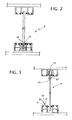
Figure 2 is a cross-section through a second embodiment of the present invention, -
Figure 3 is a cross-section through a third embodiment of the present invention, -
Figure 4 is a detailed view of the adaptation means ofFigure 1 , -
Figure 5 is a cross-section through a vertical guide means of the present system, and -
Figure 6 is a detailed view of a spacer means connected to an engagement element ofFigures 1 ,2 ,3 and5 . - With reference now to
Figures 1 and2 , asupport system 1 for space-divider partition walls comprises lower guide means 2 and upper guide means 3 suitable for supporting one ormore partition panels 4 vertically. The lower guide means 2 and the upper guide means 3 are fixed to afloor 5 and to aceiling 6, respectively, of the space selected for the installation of one ormore partition panels 4. - Each of the lower and upper guide means 2 and 3 comprises a guide, for example, a profiled section, comprising two
side walls 9 and abase wall 8 which define at least onecompartment 7 for housing the upper or lower end of thepartition panel 4, respectively. Each of theguides 2 and 3 further comprises aseparator 11, for example, a thin plate, which is engaged in a selectively removable manner on the two side walls that define thecompartment 7 and is arranged in a position substantially parallel to thebase wall 8.
According to one embodiment of the present invention, theseparator 11 extends along the entire length of the guide and, preferably but in non-limiting manner, has a reduced thickness in the region of the points of contact with the side walls of thecompartment 7 to facilitate its removal simply by mechanical force. Theseparator 11 further comprises one or more through apertures 12 which are preferably circular and enable one or more adaptation elements, which are preferably cylindrical, to be inserted and held in place, as will become clearer from the following description. - The
support system 1 for space-divider partition walls according to the present invention further comprises adaptation means which enable partition panels of different thickness to fit inside the guides and in particular the lower guide without modification of thehousing compartments 7 of the lower guide 2 and, above all, without replacement of the guide means. - As is particularly clear from
Figure 4 , each adaptation means comprises amain body 13 which is, for example but in non-limiting manner, of substantially cylindrical shape and hollow, and inside which a support element is fitted. The support element comprises apin 21 the length of which is substantially less than the height of the main body, and to one end of which is connected ahead 14 having acontact surface 15 which is intended to remain in contact with the lower end of apartition panel 4 in use. As can clearly be seen from the drawings, thecontact surface 15 is inclined towards a preferential axis so that the lower portion of thepartition 4 which is in abutment with thesurface 15 is urged by gravity towards the preferential axis. With reference toFigure 1 , themain body 13 of the adaptation means is fitted in the through aperture formed in theseparator 11 and is disposed inside thecompartment 7. Thecontact surface 15 is arranged in a manner such that it is inclined and facing outwardly relative to the lower guide 2. Once thepartition panel 4 is positioned inside thecompartment 7 of the guide 2, the lower portion of the panel is thus urged into abutment with the inner portion of theside wall 9 of the guide 2 and held in position, because of its weight, between theside wall 9 and theinclined contact surface 15. - This characteristic is extremely advantageous since it is possible to construct a partition wall by using or substituting partition panels having different thicknesses, provided that they are less than the width of the
compartment 7, not only without modifying the adaptation means but also and above all without the need to replace the profiled section 2 which constitutes the guide means of the partition wall. - According to a further embodiment of the present invention illustrated in
Figure 2 , the adaptation means comprise a head having twocontact surfaces partition panel 4 in use. As can clearly be seen from the drawings, thecontact surface 15 is inclined towards a first preferential axis whereas thesurface 17 is inclined towards a second preferential axis, opposite the first. When the lower end of thepartition panel 4 comes into abutment with thesurfaces - In this embodiment as well, it is possible to construct a partition wall by using or substituting partition panels having different thicknesses, provided that they are less than the width of the
compartment 7, not only without modifying the adaptation means but also and above all without the need to replace the profiled section 2 which constitutes the guide means of the partition wall. - Naturally, two or more adaptation means can be fitted in a single compartment, along the entire extent of the guide, so as to provide each
partition panel 4 with several support points and thus improve its stability. - Each adaptation means may also comprise actuator means which enable the height of the adaptation means to be varied relative to the guide inside which it is fitted. It is thus possible to modify the height of the
partition panel 4 that bears on the adaptation means and advantageously to compensate for any unevenness in the floor so as to level thepartition panel 4. - According to one embodiment of the present invention, the actuator means 18 comprise, preferably but in non-limiting manner, a
rotation member 19 which is engaged on thepin 21 of the support element so that its rotation causes thepin 21 to translate inside the main body, selectively varying the height of thehead 14 relative to themain body 13. The main body comprises anaperture 41, for example, a through aperture, for affording access to therotation member 19. - Naturally, persons skilled in the art will easily be able to identify different embodiments of the above-described actuator means 18 with mechanical, hydraulic, pneumatic or electrical operation or operation of any other type.
- According to a particularly advantageous characteristic of the present invention, coaxial through
holes 20 are formed in theside walls 9 of the lower guide means 2 and are situated in the region of the through apertures 12 formed in theseparator 11. In use, the adaptation means are fitted in thecompartment 7 through the through apertures 12 so that theaperture 41 faces theholes 20 formed in theside walls 9. Therotation member 19 of the adaptation means can thus be operated directly, for example but in non-limiting manner, by means of a screwdriver, without the need to remove the adaptation means from the lower guide 2. The throughholes 20 can selectively be closed so as to render them invisible from the exterior and to improve the appearance of the guide 2 by means of coveringelements 22 engaged on the outer surfaces of theside walls 9. - According to a preferred embodiment of the present invention, the
guides 2 and 3 comprise two ormore compartments 7 defined by thebase wall 8, by the twoside walls 9, and by twointermediate walls 10. As shown inFigure 1 , the lower guide 2 comprises threecompartments 7 inside each of which there is aseparator 11 which extends substantially along the entire length of the guide 2. The adaptation means can equally well be fitted in any one of thecompartments 7, inseveral compartments 7 at the same time, or in all of thecompartments 7, according to the number of partition panels to be installed and consequently according to the configuration of the partition walls to be produced. Preferably, an adaptation element having ahead 14 comprising a singleinclined surface 15 is fitted in each of thelateral compartments 7 whereas an adjustment element with ahead 14 comprising twoinclined surfaces central compartment 7. - According to a particularly advantageous characteristic of the present invention, all of the
compartments 7 are of the same size so that partition panels which have different thicknesses and or are made of different materials, for example, wooden panels or panels of another opaque material and glass panels or panels or another transparent material can be positioned without distinction therein. Moreover, should it be necessary to change the type of a partition wall already constructed with the support system of the present invention, it is possible to replace panels with panels of different types and/or thicknesses easily, not only without modifying the adaptation means but also and above all without the need to replace theprofiled sections 2 or 3 which constitute the guide means of the partition wall. - The
support system 1 for space-divider partition walls according to the present invention also comprises vertical support means, for example but in non-limiting manner, one ormore uprights 23, one of which is shown in cross-section inFigure 5 . The upright 23, which is fixed, for example, by welding or mechanical connection, between the lower guide means 2 and the upper guide means 3, comprises at least one compartment 7', preferably but in non-limiting manner, three or six compartments 7', which are also defined by side walls 9', intermediate walls 10', and a central wall 8'. In use, the compartments 7' are particularly suitable for housing the lateral ends of twoadjacent partition panels 4 so as to improve and reinforce their stability. - Although, up to this point in the description, specific reference has been made to the installation of
fixed partition panels 4, it is intended that the system of the present invention may advantageously also be used for the installation ofmovable partition panels 24. In this case, as shown inFigure 3 , afixed track 25, on which aslide 43 can run in use, is fixed inside one of thecompartments 7 of the upper guide means 3. Theslide 43 is composed, for example, of a main body to the top of which are connected running means, for example, two pairs of wheels engaged for running inside thetrack 25, and to the bottom of which are connected engagement means for engaging the upper portion of apanel 26. - For the installation of a sliding partition panel, the
separator 11 is removed from thecompartment 7 of the lower guide means 2 in the region corresponding to thecompartment 7 of the upper guide means in which the slide is installed to allow the lower end of thesliding panel 26 to be housed freely inside thecompartment 7. - According to an advantageous characteristic of the present invention, the system further comprises
covering means 29 which, in use, can conceal and/or cover the upper openings of thecompartments 7 which are not engaged by partition panels. - As is shown best in the drawings, the covering means may comprise, for example, a
plate 30 comprising projecting elements orteeth 31 formed on its lower surface. Theteeth 31 are selectively engageable onengagement elements 27. As shown in the drawings, the engagement means comprise, preferably but in non-limiting manner, respective elongate elements engaged and/or formed on the inner surfaces of theside walls 9 and of theintermediate walls 10 of the lower and upper guide means 2 and 3 and of the vertical guide means 23. Each elongate, substantially "C"-shaped element defines in its interior a "T"-shaped channel extending longitudinally relative to the wall comprising theengagement element 27. - Moreover, the system comprises spacer elements, for example, a
packing strip 28 which is fitted inside the channel of theengagement element 27 and which, in use, can prevent direct contact between the lower and upper ends of apartition panel 4 and the side and intermediate walls of theguides 2 and 3. - According to a preferred embodiment of the present invention which provides for the presence of three
compartments 7 in the lower and upper guide means 2 and 3, respectively, thesupport system 1 for partition walls for subdividing environments is also particularly suitable for the installation so so-called "sandwich panels". In this specific case, the twolateral compartments 7 of the lower and upper guide means 2 and 3 are used to house the lower and upper ends, respectively, of the two individual, mutually connected panels which normally make up each sandwich panel. - Naturally, the principle of the invention remaining the same, the forms of embodiment and the details of construction may vary widely with respect to those described and illustrated, without thereby departing from the scope of the invention.
Claims (10)
- A support system (1) for space-divider partition walls, of the type comprising:- lower guide means (2) and upper guide means (3) which extend longitudinally along a preferential axis,- the guide means (2, 3) comprising at least one compartment (7) which is defined by two side walls (9) and also extends longitudinally along the preferential axis,- the at least one compartment (7) being suitable for housing ends of one or more partition panels (4) in its interior in use, characterized in that- the system comprises adaptation means (13) disposed in the at least one compartment (7) of the lower guide means (2), the adaptation means (13) comprising at least one inclined contact surface (15) which is intended to remain in contact with the ends of one or more partition panels (4) in use.
- A system according to Claim 1, characterized in that the lower guide means (2) and the upper guide means (3) comprise, respectively, a plurality of compartments (7) which are defined by the two side walls (9) and by a plurality of intermediate walls (10) disposed inside the guide means.
- A system according to Claim 1 or Claim 2, characterized in that the adaptation means comprise a second inclined contact surface (17) opposite the first contact surface (15).
- A system according to any one of the preceding claims, characterized in that the adaptation means (13) comprise actuator means (18) which enable the height of the contact surface (15) relative to the guide means (2) to be varied in use.
- A system according to Claim 4, characterized in that the actuator means (18) comprise a rotation member (19) suitable for being rotated selectively to vary the height of the contact surface (15).
- A system according to Claim 1 or Claim 2, characterized in that it comprises at least one separator (11) which extends longitudinally along the preferential axis, the separator (11) being engaged in a selectively removable manner on the side walls (9) of the compartment (7).
- A system according to Claim 6, characterized in that at least one aperture (12), through which an adaptation means (13) can extend, is formed in the at least one separator (11).
- A system according to Claim 8, characterized in that coaxial through holes (20) are formed in the side walls (9) and in the intermediate walls (10) of the lower guide means (2) and are situated in the region of the apertures (12) to allow an operator to act on the actuator means (18) in order to vary the height of the contact surface (15).
- A system according to Claim 1 or Claim 2, characterized in that it comprises spacer elements (28) suitable for being connected to the walls (9) of the guide means (2, 3).
- A system according to Claim 1 or Claim 2, characterized in that it comprises covering means (29) engaged on the side walls (9) of the guide means (2, 3), the covering means (29) being suitable for closing one or more compartments (7).
Applications Claiming Priority (1)
| Application Number | Priority Date | Filing Date | Title |
|---|---|---|---|
| ITBO2008A000744A IT1392016B1 (en) | 2008-12-11 | 2008-12-11 | SUPPORT SYSTEM FOR ENVIRONMENT PARTITION WALLS |
Publications (3)
| Publication Number | Publication Date |
|---|---|
| EP2199481A2 true EP2199481A2 (en) | 2010-06-23 |
| EP2199481A3 EP2199481A3 (en) | 2010-10-06 |
| EP2199481B1 EP2199481B1 (en) | 2011-10-19 |
Family
ID=41800559
Family Applications (1)
| Application Number | Title | Priority Date | Filing Date |
|---|---|---|---|
| EP09178655A Active EP2199481B1 (en) | 2008-12-11 | 2009-12-10 | A support system for space-divider partition walls |
Country Status (3)
| Country | Link |
|---|---|
| EP (1) | EP2199481B1 (en) |
| AT (1) | ATE529578T1 (en) |
| IT (1) | IT1392016B1 (en) |
Cited By (2)
| Publication number | Priority date | Publication date | Assignee | Title |
|---|---|---|---|---|
| GB2557899A (en) * | 2016-10-20 | 2018-07-04 | Sheridan Sarmed | Mounting partitioning panels |
| IT202100008603A1 (en) * | 2021-04-07 | 2022-10-07 | Grandi Srl | SYSTEM FOR THE PARTITION OF A ROOM |
Families Citing this family (1)
| Publication number | Priority date | Publication date | Assignee | Title |
|---|---|---|---|---|
| US11299887B2 (en) | 2019-11-08 | 2022-04-12 | Teknion Limited | Leveling assembly |
Family Cites Families (6)
| Publication number | Priority date | Publication date | Assignee | Title |
|---|---|---|---|---|
| GB1159968A (en) * | 1966-03-24 | 1969-07-30 | Gerald Arthur Williamson | Improvements in or relating to the Construction of Dwelling Units |
| US3608266A (en) * | 1969-07-31 | 1971-09-28 | Architectural Partitions | Method and apparatus for constructing removable partition walls |
| US5644877A (en) * | 1995-07-25 | 1997-07-08 | Wood; Richard J. | Demountable ceiling closure |
| DE19624975A1 (en) * | 1996-06-22 | 1998-01-02 | Hamstein Raumbau Gmbh | Partition-mounting system on e.g. floating floor |
| GB9622702D0 (en) * | 1996-10-31 | 1997-01-08 | Komfort Systems Ltd | Partitioning system |
| US20040255539A1 (en) * | 2003-05-07 | 2004-12-23 | Beavers Dale W. | Panel-based modular wall system |
-
2008
- 2008-12-11 IT ITBO2008A000744A patent/IT1392016B1/en active
-
2009
- 2009-12-10 EP EP09178655A patent/EP2199481B1/en active Active
- 2009-12-10 AT AT09178655T patent/ATE529578T1/en not_active IP Right Cessation
Non-Patent Citations (1)
| Title |
|---|
| None |
Cited By (3)
| Publication number | Priority date | Publication date | Assignee | Title |
|---|---|---|---|---|
| GB2557899A (en) * | 2016-10-20 | 2018-07-04 | Sheridan Sarmed | Mounting partitioning panels |
| IT202100008603A1 (en) * | 2021-04-07 | 2022-10-07 | Grandi Srl | SYSTEM FOR THE PARTITION OF A ROOM |
| EP4071315A1 (en) * | 2021-04-07 | 2022-10-12 | C&G S.A.S. Di Ruggero Grandi & C. | System for partitioning a space |
Also Published As
| Publication number | Publication date |
|---|---|
| ATE529578T1 (en) | 2011-11-15 |
| ITBO20080744A1 (en) | 2010-06-12 |
| EP2199481A3 (en) | 2010-10-06 |
| IT1392016B1 (en) | 2012-02-09 |
| EP2199481B1 (en) | 2011-10-19 |
Similar Documents
| Publication | Publication Date | Title |
|---|---|---|
| US5412912A (en) | Modular slatwall assembly | |
| US4361994A (en) | Structural support for interior wall partition assembly | |
| US2970676A (en) | Framework construction | |
| EP2199481A2 (en) | A support system for space-divider partition walls | |
| WO2001051726A1 (en) | Improved panel/room divider system | |
| US4733925A (en) | Device for the suspended arrangement of juxtaposed individual tilting compartments | |
| JP6552880B2 (en) | Moving partition device | |
| EP2527553A1 (en) | Mobile room partition system | |
| EP3480411B1 (en) | Partition wall and containment device for a roll-up curtain roller for the partition wall | |
| EP2149952B1 (en) | Plural electrical mechanism carrier | |
| JP7025891B2 (en) | Moving partition device | |
| JP4154530B2 (en) | Partition and panel element mounting structure | |
| US6052944A (en) | Object with forward and subsequent lateral displacement of forward movable surfaces | |
| JP4787422B2 (en) | Moving panel articulated partition device | |
| JP4850093B2 (en) | Sliding door guide structure | |
| GB2364335A (en) | Stud wall construction | |
| EP4008872A1 (en) | Frame for sliding doors | |
| KR100391880B1 (en) | Shelf holder for good's display | |
| JP2000064467A (en) | Room structure | |
| JP2023047863A (en) | curtain wall | |
| KR20210085028A (en) | Device for opening and closing curved doors for fabricated doors | |
| RU2271421C2 (en) | Mobile composite wall structure | |
| JP2000064702A (en) | Room structure | |
| KR200297557Y1 (en) | Assembling style of mail box | |
| US727579A (en) | Construction of buildings. |
Legal Events
| Date | Code | Title | Description |
|---|---|---|---|
| PUAI | Public reference made under article 153(3) epc to a published international application that has entered the european phase |
Free format text: ORIGINAL CODE: 0009012 |
|
| AK | Designated contracting states |
Kind code of ref document: A2 Designated state(s): AT BE BG CH CY CZ DE DK EE ES FI FR GB GR HR HU IE IS IT LI LT LU LV MC MK MT NL NO PL PT RO SE SI SK SM TR |
|
| AX | Request for extension of the european patent |
Extension state: AL BA RS |
|
| PUAL | Search report despatched |
Free format text: ORIGINAL CODE: 0009013 |
|
| AK | Designated contracting states |
Kind code of ref document: A3 Designated state(s): AT BE BG CH CY CZ DE DK EE ES FI FR GB GR HR HU IE IS IT LI LT LU LV MC MK MT NL NO PL PT RO SE SI SK SM TR |
|
| AX | Request for extension of the european patent |
Extension state: AL BA RS |
|
| RIC1 | Information provided on ipc code assigned before grant |
Ipc: E04B 2/74 20060101AFI20100323BHEP Ipc: E04B 2/82 20060101ALI20100827BHEP |
|
| 17P | Request for examination filed |
Effective date: 20100910 |
|
| RIC1 | Information provided on ipc code assigned before grant |
Ipc: E04B 2/74 20060101AFI20110203BHEP Ipc: E04B 2/82 20060101ALI20110203BHEP |
|
| GRAP | Despatch of communication of intention to grant a patent |
Free format text: ORIGINAL CODE: EPIDOSNIGR1 |
|
| GRAS | Grant fee paid |
Free format text: ORIGINAL CODE: EPIDOSNIGR3 |
|
| GRAA | (expected) grant |
Free format text: ORIGINAL CODE: 0009210 |
|
| AK | Designated contracting states |
Kind code of ref document: B1 Designated state(s): AT BE BG CH CY CZ DE DK EE ES FI FR GB GR HR HU IE IS IT LI LT LU LV MC MK MT NL NO PL PT RO SE SI SK SM TR |
|
| AX | Request for extension of the european patent |
Extension state: RS |
|
| REG | Reference to a national code |
Ref country code: GB Ref legal event code: FG4D |
|
| REG | Reference to a national code |
Ref country code: CH Ref legal event code: EP |
|
| REG | Reference to a national code |
Ref country code: IE Ref legal event code: FG4D |
|
| REG | Reference to a national code |
Ref country code: CH Ref legal event code: NV Representative=s name: BRAUNPAT BRAUN EDER AG Ref country code: DE Ref legal event code: R096 Ref document number: 602009003161 Country of ref document: DE Effective date: 20111215 |
|
| REG | Reference to a national code |
Ref country code: NL Ref legal event code: VDEP Effective date: 20111019 |
|
| LTIE | Lt: invalidation of european patent or patent extension |
Effective date: 20111019 |
|
| REG | Reference to a national code |
Ref country code: AT Ref legal event code: MK05 Ref document number: 529578 Country of ref document: AT Kind code of ref document: T Effective date: 20111019 |
|
| PG25 | Lapsed in a contracting state [announced via postgrant information from national office to epo] |
Ref country code: LT Free format text: LAPSE BECAUSE OF FAILURE TO SUBMIT A TRANSLATION OF THE DESCRIPTION OR TO PAY THE FEE WITHIN THE PRESCRIBED TIME-LIMIT Effective date: 20111019 Ref country code: NO Free format text: LAPSE BECAUSE OF FAILURE TO SUBMIT A TRANSLATION OF THE DESCRIPTION OR TO PAY THE FEE WITHIN THE PRESCRIBED TIME-LIMIT Effective date: 20120119 Ref country code: BE Free format text: LAPSE BECAUSE OF FAILURE TO SUBMIT A TRANSLATION OF THE DESCRIPTION OR TO PAY THE FEE WITHIN THE PRESCRIBED TIME-LIMIT Effective date: 20111019 Ref country code: IS Free format text: LAPSE BECAUSE OF FAILURE TO SUBMIT A TRANSLATION OF THE DESCRIPTION OR TO PAY THE FEE WITHIN THE PRESCRIBED TIME-LIMIT Effective date: 20120219 |
|
| PG25 | Lapsed in a contracting state [announced via postgrant information from national office to epo] |
Ref country code: SI Free format text: LAPSE BECAUSE OF FAILURE TO SUBMIT A TRANSLATION OF THE DESCRIPTION OR TO PAY THE FEE WITHIN THE PRESCRIBED TIME-LIMIT Effective date: 20111019 Ref country code: SE Free format text: LAPSE BECAUSE OF FAILURE TO SUBMIT A TRANSLATION OF THE DESCRIPTION OR TO PAY THE FEE WITHIN THE PRESCRIBED TIME-LIMIT Effective date: 20111019 Ref country code: LV Free format text: LAPSE BECAUSE OF FAILURE TO SUBMIT A TRANSLATION OF THE DESCRIPTION OR TO PAY THE FEE WITHIN THE PRESCRIBED TIME-LIMIT Effective date: 20111019 Ref country code: HR Free format text: LAPSE BECAUSE OF FAILURE TO SUBMIT A TRANSLATION OF THE DESCRIPTION OR TO PAY THE FEE WITHIN THE PRESCRIBED TIME-LIMIT Effective date: 20111019 Ref country code: NL Free format text: LAPSE BECAUSE OF FAILURE TO SUBMIT A TRANSLATION OF THE DESCRIPTION OR TO PAY THE FEE WITHIN THE PRESCRIBED TIME-LIMIT Effective date: 20111019 Ref country code: PT Free format text: LAPSE BECAUSE OF FAILURE TO SUBMIT A TRANSLATION OF THE DESCRIPTION OR TO PAY THE FEE WITHIN THE PRESCRIBED TIME-LIMIT Effective date: 20120220 Ref country code: GR Free format text: LAPSE BECAUSE OF FAILURE TO SUBMIT A TRANSLATION OF THE DESCRIPTION OR TO PAY THE FEE WITHIN THE PRESCRIBED TIME-LIMIT Effective date: 20120120 |
|
| PG25 | Lapsed in a contracting state [announced via postgrant information from national office to epo] |
Ref country code: CY Free format text: LAPSE BECAUSE OF FAILURE TO SUBMIT A TRANSLATION OF THE DESCRIPTION OR TO PAY THE FEE WITHIN THE PRESCRIBED TIME-LIMIT Effective date: 20111019 |
|
| PG25 | Lapsed in a contracting state [announced via postgrant information from national office to epo] |
Ref country code: EE Free format text: LAPSE BECAUSE OF FAILURE TO SUBMIT A TRANSLATION OF THE DESCRIPTION OR TO PAY THE FEE WITHIN THE PRESCRIBED TIME-LIMIT Effective date: 20111019 Ref country code: CZ Free format text: LAPSE BECAUSE OF FAILURE TO SUBMIT A TRANSLATION OF THE DESCRIPTION OR TO PAY THE FEE WITHIN THE PRESCRIBED TIME-LIMIT Effective date: 20111019 Ref country code: DK Free format text: LAPSE BECAUSE OF FAILURE TO SUBMIT A TRANSLATION OF THE DESCRIPTION OR TO PAY THE FEE WITHIN THE PRESCRIBED TIME-LIMIT Effective date: 20111019 Ref country code: BG Free format text: LAPSE BECAUSE OF FAILURE TO SUBMIT A TRANSLATION OF THE DESCRIPTION OR TO PAY THE FEE WITHIN THE PRESCRIBED TIME-LIMIT Effective date: 20120119 Ref country code: MC Free format text: LAPSE BECAUSE OF NON-PAYMENT OF DUE FEES Effective date: 20111231 Ref country code: SK Free format text: LAPSE BECAUSE OF FAILURE TO SUBMIT A TRANSLATION OF THE DESCRIPTION OR TO PAY THE FEE WITHIN THE PRESCRIBED TIME-LIMIT Effective date: 20111019 |
|
| PLBE | No opposition filed within time limit |
Free format text: ORIGINAL CODE: 0009261 |
|
| STAA | Information on the status of an ep patent application or granted ep patent |
Free format text: STATUS: NO OPPOSITION FILED WITHIN TIME LIMIT |
|
| PG25 | Lapsed in a contracting state [announced via postgrant information from national office to epo] |
Ref country code: RO Free format text: LAPSE BECAUSE OF FAILURE TO SUBMIT A TRANSLATION OF THE DESCRIPTION OR TO PAY THE FEE WITHIN THE PRESCRIBED TIME-LIMIT Effective date: 20111019 Ref country code: PL Free format text: LAPSE BECAUSE OF FAILURE TO SUBMIT A TRANSLATION OF THE DESCRIPTION OR TO PAY THE FEE WITHIN THE PRESCRIBED TIME-LIMIT Effective date: 20111019 |
|
| 26N | No opposition filed |
Effective date: 20120720 |
|
| REG | Reference to a national code |
Ref country code: DE Ref legal event code: R097 Ref document number: 602009003161 Country of ref document: DE Effective date: 20120720 |
|
| REG | Reference to a national code |
Ref country code: CH Ref legal event code: PFA Owner name: CASTELLI S.P.A., IT Free format text: FORMER OWNER: HAWORTH S.P.A., IT |
|
| REG | Reference to a national code |
Ref country code: DE Ref legal event code: R082 Ref document number: 602009003161 Country of ref document: DE Representative=s name: MAIKOWSKI & NINNEMANN PATENTANWAELTE, DE |
|
| PG25 | Lapsed in a contracting state [announced via postgrant information from national office to epo] |
Ref country code: AT Free format text: LAPSE BECAUSE OF FAILURE TO SUBMIT A TRANSLATION OF THE DESCRIPTION OR TO PAY THE FEE WITHIN THE PRESCRIBED TIME-LIMIT Effective date: 20111019 |
|
| PG25 | Lapsed in a contracting state [announced via postgrant information from national office to epo] |
Ref country code: MK Free format text: LAPSE BECAUSE OF FAILURE TO SUBMIT A TRANSLATION OF THE DESCRIPTION OR TO PAY THE FEE WITHIN THE PRESCRIBED TIME-LIMIT Effective date: 20111019 Ref country code: MT Free format text: LAPSE BECAUSE OF FAILURE TO SUBMIT A TRANSLATION OF THE DESCRIPTION OR TO PAY THE FEE WITHIN THE PRESCRIBED TIME-LIMIT Effective date: 20111019 |
|
| REG | Reference to a national code |
Ref country code: DE Ref legal event code: R081 Ref document number: 602009003161 Country of ref document: DE Owner name: CASTELLI S.P.A., IT Free format text: FORMER OWNER: HAWORTH S.P.A., S. GIOVANNI IN PERSICETO, IT Effective date: 20130116 Ref country code: DE Ref legal event code: R082 Ref document number: 602009003161 Country of ref document: DE Representative=s name: MAIKOWSKI & NINNEMANN PATENTANWAELTE, DE Effective date: 20130116 Ref country code: DE Ref legal event code: R081 Ref document number: 602009003161 Country of ref document: DE Owner name: CASTELLI S.P.A., IT Free format text: FORMER OWNER: HAWORTH S.P.A., S. GIOVANNI IN PERSICETO, BOLOGNA, IT Effective date: 20130116 Ref country code: DE Ref legal event code: R082 Ref document number: 602009003161 Country of ref document: DE Representative=s name: MAIKOWSKI & NINNEMANN PATENTANWAELTE PARTNERSC, DE Effective date: 20130116 |
|
| PG25 | Lapsed in a contracting state [announced via postgrant information from national office to epo] |
Ref country code: SM Free format text: LAPSE BECAUSE OF FAILURE TO SUBMIT A TRANSLATION OF THE DESCRIPTION OR TO PAY THE FEE WITHIN THE PRESCRIBED TIME-LIMIT Effective date: 20111019 Ref country code: ES Free format text: LAPSE BECAUSE OF FAILURE TO SUBMIT A TRANSLATION OF THE DESCRIPTION OR TO PAY THE FEE WITHIN THE PRESCRIBED TIME-LIMIT Effective date: 20120130 |
|
| REG | Reference to a national code |
Ref country code: FR Ref legal event code: CD Owner name: CASTELLI S.P.A., IT Effective date: 20130409 |
|
| PG25 | Lapsed in a contracting state [announced via postgrant information from national office to epo] |
Ref country code: LU Free format text: LAPSE BECAUSE OF NON-PAYMENT OF DUE FEES Effective date: 20111210 |
|
| PG25 | Lapsed in a contracting state [announced via postgrant information from national office to epo] |
Ref country code: FI Free format text: LAPSE BECAUSE OF FAILURE TO SUBMIT A TRANSLATION OF THE DESCRIPTION OR TO PAY THE FEE WITHIN THE PRESCRIBED TIME-LIMIT Effective date: 20111019 |
|
| PG25 | Lapsed in a contracting state [announced via postgrant information from national office to epo] |
Ref country code: TR Free format text: LAPSE BECAUSE OF FAILURE TO SUBMIT A TRANSLATION OF THE DESCRIPTION OR TO PAY THE FEE WITHIN THE PRESCRIBED TIME-LIMIT Effective date: 20111019 |
|
| PG25 | Lapsed in a contracting state [announced via postgrant information from national office to epo] |
Ref country code: HU Free format text: LAPSE BECAUSE OF FAILURE TO SUBMIT A TRANSLATION OF THE DESCRIPTION OR TO PAY THE FEE WITHIN THE PRESCRIBED TIME-LIMIT Effective date: 20111019 |
|
| PGFP | Annual fee paid to national office [announced via postgrant information from national office to epo] |
Ref country code: CH Payment date: 20141219 Year of fee payment: 6 Ref country code: DE Payment date: 20141211 Year of fee payment: 6 Ref country code: IE Payment date: 20141222 Year of fee payment: 6 Ref country code: GB Payment date: 20141219 Year of fee payment: 6 |
|
| PGFP | Annual fee paid to national office [announced via postgrant information from national office to epo] |
Ref country code: FR Payment date: 20141219 Year of fee payment: 6 |
|
| REG | Reference to a national code |
Ref country code: DE Ref legal event code: R119 Ref document number: 602009003161 Country of ref document: DE |
|
| REG | Reference to a national code |
Ref country code: CH Ref legal event code: PL |
|
| GBPC | Gb: european patent ceased through non-payment of renewal fee |
Effective date: 20151210 |
|
| REG | Reference to a national code |
Ref country code: IE Ref legal event code: MM4A |
|
| REG | Reference to a national code |
Ref country code: FR Ref legal event code: ST Effective date: 20160831 |
|
| PG25 | Lapsed in a contracting state [announced via postgrant information from national office to epo] |
Ref country code: GB Free format text: LAPSE BECAUSE OF NON-PAYMENT OF DUE FEES Effective date: 20151210 Ref country code: IE Free format text: LAPSE BECAUSE OF NON-PAYMENT OF DUE FEES Effective date: 20151210 Ref country code: DE Free format text: LAPSE BECAUSE OF NON-PAYMENT OF DUE FEES Effective date: 20160701 Ref country code: CH Free format text: LAPSE BECAUSE OF NON-PAYMENT OF DUE FEES Effective date: 20151231 Ref country code: LI Free format text: LAPSE BECAUSE OF NON-PAYMENT OF DUE FEES Effective date: 20151231 |
|
| PG25 | Lapsed in a contracting state [announced via postgrant information from national office to epo] |
Ref country code: FR Free format text: LAPSE BECAUSE OF NON-PAYMENT OF DUE FEES Effective date: 20151231 |
|
| PGFP | Annual fee paid to national office [announced via postgrant information from national office to epo] |
Ref country code: IT Payment date: 20231228 Year of fee payment: 15 |