EP2198100B1 - A post and a structure comprising a post - Google Patents
A post and a structure comprising a post Download PDFInfo
- Publication number
- EP2198100B1 EP2198100B1 EP08788541A EP08788541A EP2198100B1 EP 2198100 B1 EP2198100 B1 EP 2198100B1 EP 08788541 A EP08788541 A EP 08788541A EP 08788541 A EP08788541 A EP 08788541A EP 2198100 B1 EP2198100 B1 EP 2198100B1
- Authority
- EP
- European Patent Office
- Prior art keywords
- post
- wedge
- end portion
- cross
- angled face
- Prior art date
- Legal status (The legal status is an assumption and is not a legal conclusion. Google has not performed a legal analysis and makes no representation as to the accuracy of the status listed.)
- Active
Links
Images

Classifications
-
- E—FIXED CONSTRUCTIONS
- E04—BUILDING
- E04H—BUILDINGS OR LIKE STRUCTURES FOR PARTICULAR PURPOSES; SWIMMING OR SPLASH BATHS OR POOLS; MASTS; FENCING; TENTS OR CANOPIES, IN GENERAL
- E04H12/00—Towers; Masts or poles; Chimney stacks; Water-towers; Methods of erecting such structures
- E04H12/22—Sockets or holders for poles or posts
- E04H12/2284—Means for adjusting the orientation of the post or pole
-
- E—FIXED CONSTRUCTIONS
- E04—BUILDING
- E04H—BUILDINGS OR LIKE STRUCTURES FOR PARTICULAR PURPOSES; SWIMMING OR SPLASH BATHS OR POOLS; MASTS; FENCING; TENTS OR CANOPIES, IN GENERAL
- E04H12/00—Towers; Masts or poles; Chimney stacks; Water-towers; Methods of erecting such structures
- E04H12/22—Sockets or holders for poles or posts
- E04H12/2253—Mounting poles or posts to the holder
- E04H12/2269—Mounting poles or posts to the holder in a socket
-
- E—FIXED CONSTRUCTIONS
- E04—BUILDING
- E04H—BUILDINGS OR LIKE STRUCTURES FOR PARTICULAR PURPOSES; SWIMMING OR SPLASH BATHS OR POOLS; MASTS; FENCING; TENTS OR CANOPIES, IN GENERAL
- E04H17/00—Fencing, e.g. fences, enclosures, corrals
- E04H17/14—Fences constructed of rigid elements, e.g. with additional wire fillings or with posts
- E04H17/20—Posts therefor
- E04H17/22—Anchoring means therefor, e.g. specially-shaped parts entering the ground; Struts or the like
-
- Y—GENERAL TAGGING OF NEW TECHNOLOGICAL DEVELOPMENTS; GENERAL TAGGING OF CROSS-SECTIONAL TECHNOLOGIES SPANNING OVER SEVERAL SECTIONS OF THE IPC; TECHNICAL SUBJECTS COVERED BY FORMER USPC CROSS-REFERENCE ART COLLECTIONS [XRACs] AND DIGESTS
- Y10—TECHNICAL SUBJECTS COVERED BY FORMER USPC
- Y10T—TECHNICAL SUBJECTS COVERED BY FORMER US CLASSIFICATION
- Y10T403/00—Joints and connections
- Y10T403/32—Articulated members
- Y10T403/32254—Lockable at fixed position
- Y10T403/32467—Telescoping members
- Y10T403/32475—Telescoping members having detent
- Y10T403/32501—Cam or wedge
-
- Y—GENERAL TAGGING OF NEW TECHNOLOGICAL DEVELOPMENTS; GENERAL TAGGING OF CROSS-SECTIONAL TECHNOLOGIES SPANNING OVER SEVERAL SECTIONS OF THE IPC; TECHNICAL SUBJECTS COVERED BY FORMER USPC CROSS-REFERENCE ART COLLECTIONS [XRACs] AND DIGESTS
- Y10—TECHNICAL SUBJECTS COVERED BY FORMER USPC
- Y10T—TECHNICAL SUBJECTS COVERED BY FORMER US CLASSIFICATION
- Y10T403/00—Joints and connections
- Y10T403/70—Interfitted members
- Y10T403/7062—Clamped members
- Y10T403/7064—Clamped members by wedge or cam
- Y10T403/7066—Clamped members by wedge or cam having actuator
- Y10T403/7067—Threaded actuator
- Y10T403/7069—Axially oriented
Definitions
- This invention relates to a post and particularly, but not exclusively, to an individual post or a post that forms part of a fence, barrier or similar structural feature in which the post is located in an aperture and secured therein.
- Means of securing posts and barriers for use in temporary installations are known which disclose a socket provided with a wedge arrangement that compresses against a localised point on the outer surface of a posts located therein to secure the post in place.
- the aperture in which the post is located must comprise a means for securing the post therein.
- the mechanisms associated with securing the posts are either obtrusive and/or visible when in use, thus being unattractive to look at while being susceptible to contamination from dirt and grime and the like.
- posts and barriers used in architectural installations must not only be practical to use but also be aesthetic in appearance.
- JP4113011 discloses a wedge configured to force apart the sides of a hollow post within a socket such that the diameter of the post is increased at that point and a force is applied, in a localised area of the socket and jams the post in the socket. Because the increase of diameter takes place only at the extreme end of the post, the system requires a second fix of retaining screws in order to impart rigidity to the post. This detail requires internal access to the post, and is in no way appropriate for a removable detail.
- the invention resides in a post, configured to be removably securable in an aperture and having a predetermined first cross-sectional area, the post having an end portion having an angled face; and a wedge, having a complementary angled face arranged against the angled face of the end portion, which is configured to be slidably movable at the end portion to adjust a second cross-sectional area, defined by the wedge and the end portion, wherein the angled face of the wedge is slidably movable relative to the angled face of the end portion to increase the second cross-sectional area relative to the first cross-sectional area to tightly secure the end portion within an aperture.
- the aperture may take the form of a socket, recess or may be defined by a space between two fixed objects.
- the dimensions of the aperture closely match those of the post so that there is minimal movement after the post has been inserted and before the post has been secured in the aperture.
- the post In use, the post is inserted into a socket when the second cross-sectional area, defined by the wedge and the end portion, is less than or equal to the cross-sectional area of the post.
- the shape of the end portion is contracted to allow a user to more easily insert the end portion of the post into the aperture.
- the wedge is slid along the angled face of the end portion, effectively expanding the wedge within the socket by extending the wedge beyond the surface of the post; thus the second cross-sectional area is increased relative to the first cross-sectional area.
- the post may further comprise a mechanism connected to the wedge for slidably moving the angled face of the wedge relative to the angled face of the end portion to increase the second cross-sectional area relative to the first cross-sectional area to tightly secure the end portion within an aperture.
- the mechanism may take the form of a drawbar and the drawbar may have a threaded portion thereon to engage with the wedge. A rotation of the drawbar causes the wedge to slidably move.
- the position of the wedge may alternatively be controllable via a cantilever mechanism using similar principles to those used on quick-release hubs of bicycles.
- the drawbar may extend to a distal end of the post remote the end portion or alternatively be accessed via an adjustment point located on the side of the post, the adjustment of the mechanism being implemented by a worm gear or similar arrangement.
- an exterior surface, or interface surface of the wedge may maintain a substantially parallel relationship with the longitudinal axis of the post.
- the parallel movement of the interface surface results in a force being applied to the internal surface of the socket along the entire length of the interface surface of the wedge. By doing so, this prevents a localised point-force being applied to the socket that could result in damage to the socket or an unsafely secured post.
- the post may have a square, circular, rectangular, hexagonal or polygonal cross-sectional profile.
- the post may form an integral part of a barrier, seating structure, signage, furniture or a fence.
- the post will more usually form a limb of such structures and the application of the wedge located on the angled face of the end portion of the post, or limb, is not limited to a single post and can be used in any number of structures in which a post, or a limb is to be inserted and secured in a socket or other aperture.
- the post in this invention may comprise only the lower part thereof, with any form of post, barrier or limb attached to it.
- the invention also resides in a barrier comprising at least two above-mentioned posts and having at least one cross-member extending between the posts to form the barrier.
- the posts, or limbs may extend from seating structures, display signs, fencing applications or any such object that is to be secured within a socket or other aperture in a solid manner.
- a barrier 10 includes two posts 12, each post 12 having an end portion 14 and a distal end 16.
- Crossbars 18 extend between the posts 12 to form the barrier structure 10.
- Each end portion 14 comprises an angled face 20 and a wedge 22 having a complementary angled face 24 arranged against the angled face 20 of the end portion 14.
- the end portion of each post 12 is inserted, in use, into a corresponding socket or other aperture (not shown) thus locating the end portion 14 therein.
- the barrier 10 may be fabricated from square-section mild steel tube and the barrier may take any shape, or have any number of cross-pieces depending on its application.
- a barrier may comprise a single post 12, a pair of posts (as shown in Figure 1 ) or any multiple of posts 12. At least one of the posts 12 will comprise an angled face 20 and a wedge portion 22 located thereagainst.
- the end portion of the post 12 has a wedge 22 located against the angled face 20 of the end portion 14.
- an interface (exterior) surface 26 of the wedge is positioned to be flush with the interface surface of the post 12 and the cross-sectional area across the wedge and end portion is equal to the cross-sectional area of the main body of the post 12.
- the wedge 22 In a second position, as shown in Figure 3 , the wedge 22 is moved towards the distal end 16 of the post 12, along the angled face 20 of the end portion 14, such that the interface surface 26 of the wedge extends beyond the surface of the post 12.
- the cross-sectional area defined by the wedge 22 located against the end portion 14 is greater than the cross-sectional area of the post 12.
- the interface surface of the wedge can be forced against the interior surface of an aperture (usually a socket) and thus secure the post 12 in place.
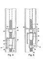
- Figure 4 is a cross-section view taken through the end portion of the post 12 when the wedge 22 is in a first position.
- the wedge includes a wedge frame 28, the wedge frame being connected to an adjustment-nut 30 that is threadably engaged with a mechanism in the form of a drawbar 32, which passes through the adjustment nut 30.
- the drawbar 32 is located centrally within the post 12 but is able to move laterally, and may bend slightly as the wedge 22 is drawn up.
- a stop nut 38 is provided at the end of the drawbar 32 to prevent the adjustment-nut 30 coming off the drawbar 32, and a stop nut 34 is provided to enable the drawbar 32 to push the wedge down in order to release the mechanism.
- the wedge frame 28 is connected upon the adjustment-nut 30 so that, in use, rotation of the drawbar 32 serves to move the adjustment-nut, which in turn moves the wedge 22 along the angled face 20 of the end portion 14. As the wedge moves along the angled face of the end portion, the interface surface 26 maintains a substantially parallel relationship with the drawbar 32.
- the end portion 14 In use, the end portion 14 would be inserted into an aperture (not shown) and locate therein. A user would then rotate the drawbar 32 to draw the adjustment-nut 30 towards the cross piece 36, whose hole is slotted or over size to allow the drawbar to move laterally, enabling the wedge 22 to move out, increasing the second cross-sectional area.
- the wedge frame 28 is connected to the adjustment-nut 30. Alternatively, the wedge frame 28 is connected to the adjustment-nut 30 such that the wedge frame 28 and the wedge 22 can move laterally with respect to the drawbar 32.
- the adjustment-nut 30 moves towards the cross piece 36 until the wedge 22 is in a second position corresponding to Figure 2 and shown by the cross-section in Figure 5 .
- the lateral adjustment of the wedge frame 28 upon the adjustment-nut 30 enables the interface surface 26 of the wedge 22 to remain substantially parallel with respect to the drawbar 32 or central axis of the post 12.
- the lateral movement of the interface surface 26 of the wedge applies a lateral force, via the adjustment-nut 30 and wedge frame 28, to the side of the aperture in which the end portion 14 is located.
- the end portion 14 is secured within the aperture (not shown).
- the drawbar 32 extends to a distal end 16 of the post 12 where an interface is provided to enable a user to rotate the drawbar 32.
- the interface may comprise a manual user interface, such as a wing-nut, or alternatively may comprise an interface suitable for engaging with a tool.
- the interface may comprise a hexagonal head for interface with a socket, spanner or Allen-key.
- the end portion of the invention allows quick and easy fitting and removal of posts, rails or pedestals etc.
- a firm and strong fixing into cheap and simple sockets is provided.
- the sockets required for such an invention are simple and can be cast into concrete or formed of steel and bolted or welded to any form of structure.
- a square cross-sectional post and corresponding square socket should be used for applications in which the posts form part of a barrier.
- a round post should be used in a corresponding round socket to allow angular adjustment in the socket.
- the shape of the post and its corresponding aperture can be rectangular, hexagonal, polygonal or of any shape, to either control the alignment of the post or to choose the orientation of the post within the aperture as desired.
- the post of the invention is not limited to being secured in a socket or other aperture but can also be used between fixed planes defined by two adjacent objects.
- the post of the invention is particularly advantageous when a square-shaped post is secured in a circular aperture. In the secured position the four corners of the post engage with the aperture such that there is substantially no free movement, or play, in a direction substantially perpendicular to the post.
- the post forms part of a structure having more than one post, and said structure is located in more than one aperture, then at least one of the posts is preferably square, and is secured in a corresponding square aperture because such an arrangement provides movement, or play, in at least one direction which is substantially perpendicular to the post, this allowing minor adjustment to be made to the position of the installed structure.
- a lip, pin or barb may be configured upon the interface surface and/or the end portion to inhibit removal of the post in safety critical applications thus preventing the post being accidentally pulled out.
- the post may be made of any suitable material but is preferably formed from laser-cut mild steel to reduce costs.
- the post of the invention comprising an adjustable end portion, or limb, is applicable for use in seating structures, display signs, fencing applications and the like.
- the post can be applied to fittings in floors, walls and ceilings and can be applied indoors or outdoors, to buildings, to boats, to aeroplanes or to vehicles or vehicle trailers.
- the post of the invention provides the ability to have removable sections of structure or architectural furniture, without the necessity of having obtrusive visible fixings.
Landscapes
- Engineering & Computer Science (AREA)
- Architecture (AREA)
- Civil Engineering (AREA)
- Structural Engineering (AREA)
- Mutual Connection Of Rods And Tubes (AREA)
- Dowels (AREA)
- Orthopedics, Nursing, And Contraception (AREA)
- Joining Of Building Structures In Genera (AREA)
- Furniture Connections (AREA)
- Fencing (AREA)
- Pivots And Pivotal Connections (AREA)
- Steering Devices For Bicycles And Motorcycles (AREA)
- Clamps And Clips (AREA)
- Refuge Islands, Traffic Blockers, Or Guard Fence (AREA)
Priority Applications (1)
| Application Number | Priority Date | Filing Date | Title |
|---|---|---|---|
| PL08788541T PL2198100T3 (pl) | 2007-09-05 | 2008-09-05 | Słupek i struktura zawierająca słupek |
Applications Claiming Priority (2)
| Application Number | Priority Date | Filing Date | Title |
|---|---|---|---|
| GB0717255A GB2452507A (en) | 2007-09-05 | 2007-09-05 | Post with wedging end |
| PCT/GB2008/003009 WO2009030920A1 (en) | 2007-09-05 | 2008-09-05 | A post and a structure comprising a post |
Publications (2)
| Publication Number | Publication Date |
|---|---|
| EP2198100A1 EP2198100A1 (en) | 2010-06-23 |
| EP2198100B1 true EP2198100B1 (en) | 2011-04-06 |
Family
ID=38640270
Family Applications (1)
| Application Number | Title | Priority Date | Filing Date |
|---|---|---|---|
| EP08788541A Active EP2198100B1 (en) | 2007-09-05 | 2008-09-05 | A post and a structure comprising a post |
Country Status (13)
| Country | Link |
|---|---|
| US (1) | US8474206B2 (pl) |
| EP (1) | EP2198100B1 (pl) |
| JP (1) | JP2010538229A (pl) |
| CN (1) | CN101868585B (pl) |
| AT (1) | ATE504707T1 (pl) |
| CA (1) | CA2736159C (pl) |
| DE (1) | DE602008006104D1 (pl) |
| DK (1) | DK2198100T3 (pl) |
| EA (1) | EA017214B1 (pl) |
| ES (1) | ES2366503T3 (pl) |
| GB (1) | GB2452507A (pl) |
| PL (1) | PL2198100T3 (pl) |
| WO (1) | WO2009030920A1 (pl) |
Families Citing this family (5)
| Publication number | Priority date | Publication date | Assignee | Title |
|---|---|---|---|---|
| US10344489B2 (en) * | 2017-05-10 | 2019-07-09 | Western Sulfur Remelters Ltd. | Adjustable support column with uplift-resisting assembly |
| KR20190052808A (ko) | 2017-11-09 | 2019-05-17 | 삼성전자주식회사 | 스탠드 및 이를 포함하는 디스플레이 장치 |
| US11376904B2 (en) * | 2018-10-26 | 2022-07-05 | N-Fab, Inc. | Receiver adapter |
| US11174645B2 (en) | 2019-07-02 | 2021-11-16 | The Landmark Group, Inc. | Elbow joint connector |
| DE102022122108B3 (de) * | 2022-09-01 | 2024-01-18 | Destaco Europe Gmbh | Positioniervorrichtung mit Stellglied und Gegenanschlag aus Keilelementen |
Family Cites Families (36)
| Publication number | Priority date | Publication date | Assignee | Title |
|---|---|---|---|---|
| GB390701A (en) * | 1932-08-06 | 1933-04-13 | Dunlop Rubber Co | Improvements in and relating to posts or supports, and sockets therefor |
| US2954638A (en) * | 1959-11-04 | 1960-10-04 | Morton Mfg Company | Upright locking socket |
| US3421726A (en) * | 1967-09-18 | 1969-01-14 | Herbert Getter | Tie-down anchor device |
| SE319286B (pl) * | 1968-05-29 | 1970-01-12 | G Andersson | |
| US3841695A (en) * | 1971-12-21 | 1974-10-15 | E Woodward | Stake pocket adapter |
| FR2256996A1 (en) * | 1974-01-04 | 1975-08-01 | Goutte Toquet Ets | Hand rail post anchoring system - uses wedges clamping post in shoe under effect of securing bolt |
| FR2317156A1 (fr) * | 1975-07-11 | 1977-02-04 | Peugeot Cycles | Dispositif de blocage pour potence de guidon |
| US4059934A (en) * | 1976-09-03 | 1977-11-29 | Senoh Kabushiki Kaisha | Arrangement for fastening an upstanding post to a floorboard |
| JPS5655108Y2 (pl) * | 1977-07-12 | 1981-12-22 | ||
| JPS5584330U (pl) | 1978-12-06 | 1980-06-10 | ||
| JPS55177580U (pl) * | 1979-06-08 | 1980-12-19 | ||
| JPS578255U (pl) * | 1980-06-17 | 1982-01-16 | ||
| JPS5740111A (en) | 1980-08-20 | 1982-03-05 | Mitsubishi Electric Corp | Position adjustor |
| CN1006818B (zh) * | 1984-10-10 | 1990-02-14 | 琼·雅克;博尔曼 | 杆柱基础支座 |
| FR2588894B1 (fr) * | 1985-10-17 | 1988-04-08 | Pont A Mousson | Balustrade de protection |
| US5022134A (en) * | 1986-10-06 | 1991-06-11 | Austpole Industries Limited | Method of repairing/replacing a pole and associated pole replacement system |
| JPS6368521U (pl) * | 1986-10-24 | 1988-05-09 | ||
| US4850733A (en) * | 1988-12-27 | 1989-07-25 | Thurston, Inc. | Expander for a seat post inserted in a bicycle frame tube |
| JPH04113011A (ja) * | 1990-08-31 | 1992-04-14 | Daamen Per | 柱素子留付けクランプ |
| DE4135102C2 (de) * | 1991-10-24 | 1993-11-11 | Koenig & Bauer Ag | Lagerzapfen für Papierleitwalzen von Rotationsdruckmaschinen |
| JPH0561510U (ja) * | 1992-01-30 | 1993-08-13 | タキロン株式会社 | パイプ接続具 |
| US5251494A (en) * | 1992-09-18 | 1993-10-12 | Edwards Craig H | Light-weight, direct fixing device for handlebar stem |
| US5680798A (en) * | 1995-11-09 | 1997-10-28 | Dia-Compe, Taiwan Co., Ltd. | Handlebar stem assembly and fork of a bicycle having expander nut structure |
| JPH09209457A (ja) | 1996-02-06 | 1997-08-12 | Tokyu Constr Co Ltd | あと施工アンカーおよびその定着方法 |
| AU3511797A (en) * | 1996-07-02 | 1998-01-21 | David S. Orton | Cast concrete fence posts and cast concrete bases for said posts |
| JPH11210719A (ja) | 1998-01-23 | 1999-08-03 | Kanei Sangyo Kk | 中空軸の接続構造 |
| CN2375708Y (zh) * | 1999-07-08 | 2000-04-26 | 蒙理明 | 组装式钢筋混凝土围墙构件 |
| US6457895B1 (en) * | 2000-07-05 | 2002-10-01 | Mark T. Salman | Flush mount breakaway post coupler |
| US6749383B1 (en) * | 2001-01-09 | 2004-06-15 | Benedict Engineering Co. | Track mounted stanchion and clamp assemblies for storage and dunnage systems |
| JP2002276626A (ja) * | 2001-03-21 | 2002-09-25 | Iris Ohyama Inc | パイプ連結部材 |
| GB2387609B (en) * | 2002-04-17 | 2005-09-28 | Hadley Ind Plc | Security fencing |
| CN2644575Y (zh) * | 2003-07-01 | 2004-09-29 | 浙江中南建设集团有限公司 | 不设抗剪键的门式钢架柱脚 |
| ZA200601811B (en) * | 2003-09-19 | 2007-08-29 | A C N 118094 Pty Ltd | Handrail or top rail, post and panel assembly and connector therefor |
| FR2863294B1 (fr) | 2003-12-05 | 2006-06-02 | Actis Ets | Support d'ancrage pour un montant d'une structure |
| US7055807B2 (en) * | 2004-06-25 | 2006-06-06 | Pool Cover Corporation | Expandable pole socket with twist and lock insert |
| US7802768B2 (en) * | 2005-04-29 | 2010-09-28 | Carnevali Jeffrey D | Telescoping pole mount |
-
2007
- 2007-09-05 GB GB0717255A patent/GB2452507A/en not_active Withdrawn
-
2008
- 2008-09-05 PL PL08788541T patent/PL2198100T3/pl unknown
- 2008-09-05 CA CA2736159A patent/CA2736159C/en active Active
- 2008-09-05 CN CN2008801148579A patent/CN101868585B/zh not_active Expired - Fee Related
- 2008-09-05 DK DK08788541.4T patent/DK2198100T3/da active
- 2008-09-05 US US12/676,660 patent/US8474206B2/en active Active
- 2008-09-05 JP JP2010523586A patent/JP2010538229A/ja active Pending
- 2008-09-05 WO PCT/GB2008/003009 patent/WO2009030920A1/en not_active Ceased
- 2008-09-05 ES ES08788541T patent/ES2366503T3/es active Active
- 2008-09-05 DE DE602008006104T patent/DE602008006104D1/de active Active
- 2008-09-05 EA EA201070333A patent/EA017214B1/ru not_active IP Right Cessation
- 2008-09-05 AT AT08788541T patent/ATE504707T1/de active
- 2008-09-05 EP EP08788541A patent/EP2198100B1/en active Active
Also Published As
| Publication number | Publication date |
|---|---|
| CN101868585A (zh) | 2010-10-20 |
| DK2198100T3 (da) | 2011-08-01 |
| ATE504707T1 (de) | 2011-04-15 |
| DE602008006104D1 (de) | 2011-05-19 |
| JP2010538229A (ja) | 2010-12-09 |
| US8474206B2 (en) | 2013-07-02 |
| US20100300039A1 (en) | 2010-12-02 |
| GB2452507A (en) | 2009-03-11 |
| PL2198100T3 (pl) | 2011-09-30 |
| CA2736159A1 (en) | 2009-03-12 |
| EP2198100A1 (en) | 2010-06-23 |
| ES2366503T3 (es) | 2011-10-20 |
| EA201070333A1 (ru) | 2010-10-29 |
| WO2009030920A1 (en) | 2009-03-12 |
| CA2736159C (en) | 2021-09-14 |
| HK1145039A1 (en) | 2011-03-25 |
| EA017214B1 (ru) | 2012-10-30 |
| CN101868585B (zh) | 2012-08-08 |
| GB0717255D0 (en) | 2007-10-17 |
Similar Documents
| Publication | Publication Date | Title |
|---|---|---|
| EP2198100B1 (en) | A post and a structure comprising a post | |
| US10104964B2 (en) | Supporting an object at a window of a building by applying opposing forces to an interior surface and an exterior surface of the building | |
| EP3572602B1 (en) | Vertical cable barrier | |
| EP3175127B1 (de) | Eckverbinder für stabförmige profilelemente | |
| AT6961U2 (de) | Verstell- und fixiervorrichtung | |
| HK1145039B (en) | A post and a structure comprising a post | |
| CN116802370A (zh) | 一种脚手架连接元件、其部件和相关方法 | |
| EP2455563A2 (de) | Kopfstück zum stirnseitigen Aufsetzen auf eine Baustütze sowie Verfahren | |
| JP2024517794A (ja) | 適応可能なフェンスブレーシング | |
| WO2013162452A1 (en) | Holding device for a frame member of a balcony glazing | |
| DE102006041211A1 (de) | Befestigungsvorrichtung für Profilrohre | |
| GB2265932A (en) | "Former for use in the construction of a brickwork aperture" | |
| DE102009010428A1 (de) | Vorrichtung zur Verbindung von Profilschienen mit Objekten | |
| EP1659229B1 (de) | Montagefuss und Sanitärelement | |
| DE202009002494U1 (de) | Vorrichtung zur Verbindung von Profilschienen mit Objekten | |
| DE19728640A1 (de) | Arbeits-, Lagerungs- u. Montage-FIX-Ständer mit automatischer Hebevorrichtung zur freien oder, mittels automatischer Schnellfixierung zwischen Decken o. Wänden, schrankenlosen Aufstellungsmöglichkeit | |
| DE29804772U1 (de) | Sanitäres Vorwandsystem, insbesondere selbsttragendes WC-Element | |
| DE202016105492U1 (de) | Hilfsmittel für die Montage von Möbelstücken | |
| AU733572B1 (en) | A panel fixing system | |
| JP2022042552A (ja) | フレーム付きデッキ、フレーム付きデッキの製造方法 | |
| DE202009013656U1 (de) | Wandhalterung | |
| AT510059A1 (de) | Verbindungsvorrichtung zum verbinden von miteinander zu verbindenden gegenständen sowie konstruktionselement und verwendung | |
| DE102020119470A1 (de) | Haltevorrichtung zur lösbaren Festlegung eines Funktionselements an einer Oberfläche | |
| JP2019127791A (ja) | 擬木柵における支柱と横木の連結構造 | |
| DE29714780U1 (de) | Arbeits-, Lagerungs- und Montage-Fix-Ständer mit automatischer Hebevorrichtung zur freien oder mittels automatischer Schnellfixierung zwischen Decken oder Wänden, schrankenlosen Aufstellungsmöglichkeit |
Legal Events
| Date | Code | Title | Description |
|---|---|---|---|
| PUAI | Public reference made under article 153(3) epc to a published international application that has entered the european phase |
Free format text: ORIGINAL CODE: 0009012 |
|
| 17P | Request for examination filed |
Effective date: 20100331 |
|
| AK | Designated contracting states |
Kind code of ref document: A1 Designated state(s): AT BE BG CH CY CZ DE DK EE ES FI FR GB GR HR HU IE IS IT LI LT LU LV MC MT NL NO PL PT RO SE SI SK TR |
|
| AX | Request for extension of the european patent |
Extension state: AL BA MK RS |
|
| GRAP | Despatch of communication of intention to grant a patent |
Free format text: ORIGINAL CODE: EPIDOSNIGR1 |
|
| DAX | Request for extension of the european patent (deleted) | ||
| GRAS | Grant fee paid |
Free format text: ORIGINAL CODE: EPIDOSNIGR3 |
|
| GRAA | (expected) grant |
Free format text: ORIGINAL CODE: 0009210 |
|
| REG | Reference to a national code |
Ref country code: HK Ref legal event code: DE Ref document number: 1145039 Country of ref document: HK |
|
| AK | Designated contracting states |
Kind code of ref document: B1 Designated state(s): AT BE BG CH CY CZ DE DK EE ES FI FR GB GR HR HU IE IS IT LI LT LU LV MC MT NL NO PL PT RO SE SI SK TR |
|
| REG | Reference to a national code |
Ref country code: GB Ref legal event code: FG4D |
|
| REG | Reference to a national code |
Ref country code: CH Ref legal event code: EP |
|
| REG | Reference to a national code |
Ref country code: IE Ref legal event code: FG4D |
|
| REF | Corresponds to: |
Ref document number: 602008006104 Country of ref document: DE Date of ref document: 20110519 Kind code of ref document: P |
|
| REG | Reference to a national code |
Ref country code: DE Ref legal event code: R096 Ref document number: 602008006104 Country of ref document: DE Effective date: 20110519 |
|
| REG | Reference to a national code |
Ref country code: NL Ref legal event code: T3 |
|
| REG | Reference to a national code |
Ref country code: CH Ref legal event code: NV Representative=s name: SERVOPATENT GMBH |
|
| REG | Reference to a national code |
Ref country code: SE Ref legal event code: TRGR |
|
| REG | Reference to a national code |
Ref country code: DK Ref legal event code: T3 |
|
| PG25 | Lapsed in a contracting state [announced via postgrant information from national office to epo] |
Ref country code: SI Free format text: LAPSE BECAUSE OF FAILURE TO SUBMIT A TRANSLATION OF THE DESCRIPTION OR TO PAY THE FEE WITHIN THE PRESCRIBED TIME-LIMIT Effective date: 20110406 |
|
| LTIE | Lt: invalidation of european patent or patent extension |
Effective date: 20110406 |
|
| REG | Reference to a national code |
Ref country code: PL Ref legal event code: T3 |
|
| REG | Reference to a national code |
Ref country code: ES Ref legal event code: FG2A Ref document number: 2366503 Country of ref document: ES Kind code of ref document: T3 Effective date: 20111020 |
|
| PG25 | Lapsed in a contracting state [announced via postgrant information from national office to epo] |
Ref country code: LT Free format text: LAPSE BECAUSE OF FAILURE TO SUBMIT A TRANSLATION OF THE DESCRIPTION OR TO PAY THE FEE WITHIN THE PRESCRIBED TIME-LIMIT Effective date: 20110406 Ref country code: PT Free format text: LAPSE BECAUSE OF FAILURE TO SUBMIT A TRANSLATION OF THE DESCRIPTION OR TO PAY THE FEE WITHIN THE PRESCRIBED TIME-LIMIT Effective date: 20110808 Ref country code: HR Free format text: LAPSE BECAUSE OF FAILURE TO SUBMIT A TRANSLATION OF THE DESCRIPTION OR TO PAY THE FEE WITHIN THE PRESCRIBED TIME-LIMIT Effective date: 20110406 Ref country code: NO Free format text: LAPSE BECAUSE OF FAILURE TO SUBMIT A TRANSLATION OF THE DESCRIPTION OR TO PAY THE FEE WITHIN THE PRESCRIBED TIME-LIMIT Effective date: 20110706 |
|
| PG25 | Lapsed in a contracting state [announced via postgrant information from national office to epo] |
Ref country code: GR Free format text: LAPSE BECAUSE OF FAILURE TO SUBMIT A TRANSLATION OF THE DESCRIPTION OR TO PAY THE FEE WITHIN THE PRESCRIBED TIME-LIMIT Effective date: 20110707 Ref country code: IS Free format text: LAPSE BECAUSE OF FAILURE TO SUBMIT A TRANSLATION OF THE DESCRIPTION OR TO PAY THE FEE WITHIN THE PRESCRIBED TIME-LIMIT Effective date: 20110806 Ref country code: FI Free format text: LAPSE BECAUSE OF FAILURE TO SUBMIT A TRANSLATION OF THE DESCRIPTION OR TO PAY THE FEE WITHIN THE PRESCRIBED TIME-LIMIT Effective date: 20110406 Ref country code: LV Free format text: LAPSE BECAUSE OF FAILURE TO SUBMIT A TRANSLATION OF THE DESCRIPTION OR TO PAY THE FEE WITHIN THE PRESCRIBED TIME-LIMIT Effective date: 20110406 Ref country code: CY Free format text: LAPSE BECAUSE OF FAILURE TO SUBMIT A TRANSLATION OF THE DESCRIPTION OR TO PAY THE FEE WITHIN THE PRESCRIBED TIME-LIMIT Effective date: 20110406 |
|
| REG | Reference to a national code |
Ref country code: HK Ref legal event code: GR Ref document number: 1145039 Country of ref document: HK |
|
| RAP2 | Party data changed (patent owner data changed or rights of a patent transferred) |
Owner name: STEELDECK INDUSTRIES LIMITED |
|
| PG25 | Lapsed in a contracting state [announced via postgrant information from national office to epo] |
Ref country code: EE Free format text: LAPSE BECAUSE OF FAILURE TO SUBMIT A TRANSLATION OF THE DESCRIPTION OR TO PAY THE FEE WITHIN THE PRESCRIBED TIME-LIMIT Effective date: 20110406 |
|
| PLBE | No opposition filed within time limit |
Free format text: ORIGINAL CODE: 0009261 |
|
| STAA | Information on the status of an ep patent application or granted ep patent |
Free format text: STATUS: NO OPPOSITION FILED WITHIN TIME LIMIT |
|
| PG25 | Lapsed in a contracting state [announced via postgrant information from national office to epo] |
Ref country code: SK Free format text: LAPSE BECAUSE OF FAILURE TO SUBMIT A TRANSLATION OF THE DESCRIPTION OR TO PAY THE FEE WITHIN THE PRESCRIBED TIME-LIMIT Effective date: 20110406 Ref country code: RO Free format text: LAPSE BECAUSE OF FAILURE TO SUBMIT A TRANSLATION OF THE DESCRIPTION OR TO PAY THE FEE WITHIN THE PRESCRIBED TIME-LIMIT Effective date: 20110406 |
|
| 26N | No opposition filed |
Effective date: 20120110 |
|
| PG25 | Lapsed in a contracting state [announced via postgrant information from national office to epo] |
Ref country code: MC Free format text: LAPSE BECAUSE OF NON-PAYMENT OF DUE FEES Effective date: 20110930 |
|
| PGFP | Annual fee paid to national office [announced via postgrant information from national office to epo] |
Ref country code: IE Payment date: 20120329 Year of fee payment: 4 |
|
| REG | Reference to a national code |
Ref country code: DK Ref legal event code: EBP |
|
| REG | Reference to a national code |
Ref country code: DE Ref legal event code: R097 Ref document number: 602008006104 Country of ref document: DE Effective date: 20120110 |
|
| REG | Reference to a national code |
Ref country code: SE Ref legal event code: EUG |
|
| PG25 | Lapsed in a contracting state [announced via postgrant information from national office to epo] |
Ref country code: DK Free format text: LAPSE BECAUSE OF NON-PAYMENT OF DUE FEES Effective date: 20110930 |
|
| PGFP | Annual fee paid to national office [announced via postgrant information from national office to epo] |
Ref country code: ES Payment date: 20120418 Year of fee payment: 4 Ref country code: IT Payment date: 20110930 Year of fee payment: 4 |
|
| PG25 | Lapsed in a contracting state [announced via postgrant information from national office to epo] |
Ref country code: MT Free format text: LAPSE BECAUSE OF FAILURE TO SUBMIT A TRANSLATION OF THE DESCRIPTION OR TO PAY THE FEE WITHIN THE PRESCRIBED TIME-LIMIT Effective date: 20110406 |
|
| PG25 | Lapsed in a contracting state [announced via postgrant information from national office to epo] |
Ref country code: SE Free format text: LAPSE BECAUSE OF NON-PAYMENT OF DUE FEES Effective date: 20110906 Ref country code: CZ Free format text: LAPSE BECAUSE OF NON-PAYMENT OF DUE FEES Effective date: 20120905 |
|
| REG | Reference to a national code |
Ref country code: CH Ref legal event code: PL |
|
| PG25 | Lapsed in a contracting state [announced via postgrant information from national office to epo] |
Ref country code: LU Free format text: LAPSE BECAUSE OF NON-PAYMENT OF DUE FEES Effective date: 20110905 |
|
| PGFP | Annual fee paid to national office [announced via postgrant information from national office to epo] |
Ref country code: NL Payment date: 20130326 Year of fee payment: 5 |
|
| REG | Reference to a national code |
Ref country code: IE Ref legal event code: MM4A |
|
| PG25 | Lapsed in a contracting state [announced via postgrant information from national office to epo] |
Ref country code: BG Free format text: LAPSE BECAUSE OF FAILURE TO SUBMIT A TRANSLATION OF THE DESCRIPTION OR TO PAY THE FEE WITHIN THE PRESCRIBED TIME-LIMIT Effective date: 20110706 |
|
| PG25 | Lapsed in a contracting state [announced via postgrant information from national office to epo] |
Ref country code: IE Free format text: LAPSE BECAUSE OF NON-PAYMENT OF DUE FEES Effective date: 20120905 Ref country code: CH Free format text: LAPSE BECAUSE OF NON-PAYMENT OF DUE FEES Effective date: 20120930 Ref country code: LI Free format text: LAPSE BECAUSE OF NON-PAYMENT OF DUE FEES Effective date: 20120930 |
|
| PGFP | Annual fee paid to national office [announced via postgrant information from national office to epo] |
Ref country code: DE Payment date: 20130328 Year of fee payment: 5 Ref country code: BE Payment date: 20130326 Year of fee payment: 5 |
|
| PGFP | Annual fee paid to national office [announced via postgrant information from national office to epo] |
Ref country code: FR Payment date: 20130418 Year of fee payment: 5 |
|
| PG25 | Lapsed in a contracting state [announced via postgrant information from national office to epo] |
Ref country code: TR Free format text: LAPSE BECAUSE OF FAILURE TO SUBMIT A TRANSLATION OF THE DESCRIPTION OR TO PAY THE FEE WITHIN THE PRESCRIBED TIME-LIMIT Effective date: 20110406 |
|
| PG25 | Lapsed in a contracting state [announced via postgrant information from national office to epo] |
Ref country code: HU Free format text: LAPSE BECAUSE OF FAILURE TO SUBMIT A TRANSLATION OF THE DESCRIPTION OR TO PAY THE FEE WITHIN THE PRESCRIBED TIME-LIMIT Effective date: 20110406 |
|
| PG25 | Lapsed in a contracting state [announced via postgrant information from national office to epo] |
Ref country code: PL Free format text: LAPSE BECAUSE OF NON-PAYMENT OF DUE FEES Effective date: 20120905 |
|
| REG | Reference to a national code |
Ref country code: PL Ref legal event code: LAPE |
|
| BERE | Be: lapsed |
Owner name: STEELDECK INDUSTRIES LTD Effective date: 20130930 |
|
| REG | Reference to a national code |
Ref country code: NL Ref legal event code: V1 Effective date: 20140401 |
|
| GBPC | Gb: european patent ceased through non-payment of renewal fee |
Effective date: 20130905 |
|
| REG | Reference to a national code |
Ref country code: FR Ref legal event code: ST Effective date: 20140530 |
|
| REG | Reference to a national code |
Ref country code: DE Ref legal event code: R119 Ref document number: 602008006104 Country of ref document: DE Effective date: 20140401 |
|
| PG25 | Lapsed in a contracting state [announced via postgrant information from national office to epo] |
Ref country code: BE Free format text: LAPSE BECAUSE OF NON-PAYMENT OF DUE FEES Effective date: 20130930 Ref country code: GB Free format text: LAPSE BECAUSE OF NON-PAYMENT OF DUE FEES Effective date: 20130905 |
|
| PG25 | Lapsed in a contracting state [announced via postgrant information from national office to epo] |
Ref country code: NL Free format text: LAPSE BECAUSE OF NON-PAYMENT OF DUE FEES Effective date: 20140401 Ref country code: FR Free format text: LAPSE BECAUSE OF NON-PAYMENT OF DUE FEES Effective date: 20130930 Ref country code: DE Free format text: LAPSE BECAUSE OF NON-PAYMENT OF DUE FEES Effective date: 20140401 Ref country code: IT Free format text: LAPSE BECAUSE OF NON-PAYMENT OF DUE FEES Effective date: 20130905 |
|
| REG | Reference to a national code |
Ref country code: ES Ref legal event code: FD2A Effective date: 20141007 |
|
| REG | Reference to a national code |
Ref country code: AT Ref legal event code: MM01 Ref document number: 504707 Country of ref document: AT Kind code of ref document: T Effective date: 20130905 |
|
| PG25 | Lapsed in a contracting state [announced via postgrant information from national office to epo] |
Ref country code: ES Free format text: LAPSE BECAUSE OF NON-PAYMENT OF DUE FEES Effective date: 20130906 |
|
| PG25 | Lapsed in a contracting state [announced via postgrant information from national office to epo] |
Ref country code: AT Free format text: LAPSE BECAUSE OF NON-PAYMENT OF DUE FEES Effective date: 20130905 |
|
| REG | Reference to a national code |
Ref country code: GB Ref legal event code: S28 Free format text: APPLICATION FILED |
|
| REG | Reference to a national code |
Ref country code: GB Ref legal event code: S28 Free format text: RESTORATION ALLOWED Effective date: 20150616 |
|
| PGFP | Annual fee paid to national office [announced via postgrant information from national office to epo] |
Ref country code: GB Payment date: 20250924 Year of fee payment: 18 |