EP2196677A1 - Machine rotative à fluide - Google Patents
Machine rotative à fluide Download PDFInfo
- Publication number
- EP2196677A1 EP2196677A1 EP08831266A EP08831266A EP2196677A1 EP 2196677 A1 EP2196677 A1 EP 2196677A1 EP 08831266 A EP08831266 A EP 08831266A EP 08831266 A EP08831266 A EP 08831266A EP 2196677 A1 EP2196677 A1 EP 2196677A1
- Authority
- EP
- European Patent Office
- Prior art keywords
- eccentric
- rotation
- swing
- piston
- type piston
- Prior art date
- Legal status (The legal status is an assumption and is not a legal conclusion. Google has not performed a legal analysis and makes no representation as to the accuracy of the status listed.)
- Withdrawn
Links
Images


Classifications
-
- F—MECHANICAL ENGINEERING; LIGHTING; HEATING; WEAPONS; BLASTING
- F04—POSITIVE - DISPLACEMENT MACHINES FOR LIQUIDS; PUMPS FOR LIQUIDS OR ELASTIC FLUIDS
- F04C—ROTARY-PISTON, OR OSCILLATING-PISTON, POSITIVE-DISPLACEMENT MACHINES FOR LIQUIDS; ROTARY-PISTON, OR OSCILLATING-PISTON, POSITIVE-DISPLACEMENT PUMPS
- F04C18/00—Rotary-piston pumps specially adapted for elastic fluids
- F04C18/30—Rotary-piston pumps specially adapted for elastic fluids having the characteristics covered by two or more of groups F04C18/02, F04C18/08, F04C18/22, F04C18/24, F04C18/48, or having the characteristics covered by one of these groups together with some other type of movement between co-operating members
- F04C18/32—Rotary-piston pumps specially adapted for elastic fluids having the characteristics covered by two or more of groups F04C18/02, F04C18/08, F04C18/22, F04C18/24, F04C18/48, or having the characteristics covered by one of these groups together with some other type of movement between co-operating members having both the movement defined in group F04C18/02 and relative reciprocation between the co-operating members
-
- F—MECHANICAL ENGINEERING; LIGHTING; HEATING; WEAPONS; BLASTING
- F04—POSITIVE - DISPLACEMENT MACHINES FOR LIQUIDS; PUMPS FOR LIQUIDS OR ELASTIC FLUIDS
- F04C—ROTARY-PISTON, OR OSCILLATING-PISTON, POSITIVE-DISPLACEMENT MACHINES FOR LIQUIDS; ROTARY-PISTON, OR OSCILLATING-PISTON, POSITIVE-DISPLACEMENT PUMPS
- F04C18/00—Rotary-piston pumps specially adapted for elastic fluids
- F04C18/02—Rotary-piston pumps specially adapted for elastic fluids of arcuate-engagement type, i.e. with circular translatory movement of co-operating members, each member having the same number of teeth or tooth-equivalents
- F04C18/04—Rotary-piston pumps specially adapted for elastic fluids of arcuate-engagement type, i.e. with circular translatory movement of co-operating members, each member having the same number of teeth or tooth-equivalents of internal-axis type
- F04C18/045—Rotary-piston pumps specially adapted for elastic fluids of arcuate-engagement type, i.e. with circular translatory movement of co-operating members, each member having the same number of teeth or tooth-equivalents of internal-axis type having a C-shaped piston
-
- F—MECHANICAL ENGINEERING; LIGHTING; HEATING; WEAPONS; BLASTING
- F04—POSITIVE - DISPLACEMENT MACHINES FOR LIQUIDS; PUMPS FOR LIQUIDS OR ELASTIC FLUIDS
- F04C—ROTARY-PISTON, OR OSCILLATING-PISTON, POSITIVE-DISPLACEMENT MACHINES FOR LIQUIDS; ROTARY-PISTON, OR OSCILLATING-PISTON, POSITIVE-DISPLACEMENT PUMPS
- F04C23/00—Combinations of two or more pumps, each being of rotary-piston or oscillating-piston type, specially adapted for elastic fluids; Pumping installations specially adapted for elastic fluids; Multi-stage pumps specially adapted for elastic fluids
- F04C23/001—Combinations of two or more pumps, each being of rotary-piston or oscillating-piston type, specially adapted for elastic fluids; Pumping installations specially adapted for elastic fluids; Multi-stage pumps specially adapted for elastic fluids of similar working principle
-
- F—MECHANICAL ENGINEERING; LIGHTING; HEATING; WEAPONS; BLASTING
- F04—POSITIVE - DISPLACEMENT MACHINES FOR LIQUIDS; PUMPS FOR LIQUIDS OR ELASTIC FLUIDS
- F04C—ROTARY-PISTON, OR OSCILLATING-PISTON, POSITIVE-DISPLACEMENT MACHINES FOR LIQUIDS; ROTARY-PISTON, OR OSCILLATING-PISTON, POSITIVE-DISPLACEMENT PUMPS
- F04C23/00—Combinations of two or more pumps, each being of rotary-piston or oscillating-piston type, specially adapted for elastic fluids; Pumping installations specially adapted for elastic fluids; Multi-stage pumps specially adapted for elastic fluids
- F04C23/008—Hermetic pumps
-
- F—MECHANICAL ENGINEERING; LIGHTING; HEATING; WEAPONS; BLASTING
- F04—POSITIVE - DISPLACEMENT MACHINES FOR LIQUIDS; PUMPS FOR LIQUIDS OR ELASTIC FLUIDS
- F04C—ROTARY-PISTON, OR OSCILLATING-PISTON, POSITIVE-DISPLACEMENT MACHINES FOR LIQUIDS; ROTARY-PISTON, OR OSCILLATING-PISTON, POSITIVE-DISPLACEMENT PUMPS
- F04C29/00—Component parts, details or accessories of pumps or pumping installations, not provided for in groups F04C18/00 - F04C28/00
- F04C29/0021—Systems for the equilibration of forces acting on the pump
-
- F—MECHANICAL ENGINEERING; LIGHTING; HEATING; WEAPONS; BLASTING
- F01—MACHINES OR ENGINES IN GENERAL; ENGINE PLANTS IN GENERAL; STEAM ENGINES
- F01C—ROTARY-PISTON OR OSCILLATING-PISTON MACHINES OR ENGINES
- F01C21/00—Component parts, details or accessories not provided for in groups F01C1/00 - F01C20/00
- F01C21/08—Rotary pistons
-
- F—MECHANICAL ENGINEERING; LIGHTING; HEATING; WEAPONS; BLASTING
- F04—POSITIVE - DISPLACEMENT MACHINES FOR LIQUIDS; PUMPS FOR LIQUIDS OR ELASTIC FLUIDS
- F04C—ROTARY-PISTON, OR OSCILLATING-PISTON, POSITIVE-DISPLACEMENT MACHINES FOR LIQUIDS; ROTARY-PISTON, OR OSCILLATING-PISTON, POSITIVE-DISPLACEMENT PUMPS
- F04C18/00—Rotary-piston pumps specially adapted for elastic fluids
- F04C18/30—Rotary-piston pumps specially adapted for elastic fluids having the characteristics covered by two or more of groups F04C18/02, F04C18/08, F04C18/22, F04C18/24, F04C18/48, or having the characteristics covered by one of these groups together with some other type of movement between co-operating members
- F04C18/34—Rotary-piston pumps specially adapted for elastic fluids having the characteristics covered by two or more of groups F04C18/02, F04C18/08, F04C18/22, F04C18/24, F04C18/48, or having the characteristics covered by one of these groups together with some other type of movement between co-operating members having the movement defined in group F04C18/08 or F04C18/22 and relative reciprocation between the co-operating members
- F04C18/356—Rotary-piston pumps specially adapted for elastic fluids having the characteristics covered by two or more of groups F04C18/02, F04C18/08, F04C18/22, F04C18/24, F04C18/48, or having the characteristics covered by one of these groups together with some other type of movement between co-operating members having the movement defined in group F04C18/08 or F04C18/22 and relative reciprocation between the co-operating members with vanes reciprocating with respect to the outer member
-
- F—MECHANICAL ENGINEERING; LIGHTING; HEATING; WEAPONS; BLASTING
- F04—POSITIVE - DISPLACEMENT MACHINES FOR LIQUIDS; PUMPS FOR LIQUIDS OR ELASTIC FLUIDS
- F04C—ROTARY-PISTON, OR OSCILLATING-PISTON, POSITIVE-DISPLACEMENT MACHINES FOR LIQUIDS; ROTARY-PISTON, OR OSCILLATING-PISTON, POSITIVE-DISPLACEMENT PUMPS
- F04C2270/00—Control; Monitoring or safety arrangements
- F04C2270/12—Vibration
Definitions
- the present invention relates to a rotary fluid machine, and particularly relates to a rotary fluid machine in which eccentric-rotation-type piston mechanisms including cylinders with annular cylinder chambers, and annular pistons eccentrically accommodated in the cylinder chambers are stacked in two tiers.
- Such a rotary fluid machine includes an eccentric-rotation-type piston mechanism which includes a cylinder with a cylinder chamber, and a piston eccentrically accommodated in the cylinder chamber, and which compresses fluid depending on a volumetric change of the cylinder chamber in response to the eccentric rotation of the piston.
- Patent Document 1 discloses a compressor including two eccentric-rotation-type piston mechanisms (compression mechanisms).
- the compressor of Patent Document 1 includes a drive motor; a drive shaft driven by the drive motor; and first and second eccentric-rotation-type piston mechanisms which connected to the drive shaft, and which are stacked in two tiers.
- the compressor can be switched between a compression operation in a single stage and a compression operation in double stages.
- Patent Document 2 discloses a compressor including an eccentric-rotation-type piston mechanism provided with cylinder having annular cylinder chambers, and with an annular piston eccentrically accommodated in the cylinder chambers.
- the annular piston is formed in a C-shape, i.e., a part of the annular ring splits, and is integrally formed with a housing fixed to a casing of the compressor.
- the cylinder is connected to an eccentric portion of a drive shaft of the compressor, and is integrally formed with a blade extending from an inner circumferential wall surface in the annular cylinder chamber to an outer circumferential wall surface in the annular cylinder chamber so as to penetrate through the split portion of the annular piston.
- Swing bushes are provided between the blade and the annular piston, and the annular piston and the cylinder are connected to each other through the swing bushes so as to be capable of swinging.
- the eccentric-rotation-type piston mechanisms described in Patent Document 2 are stacked in two tiers as described in Patent Document 1, thereby realizing a rotary fluid machine.
- vibration of the rotary fluid machine may be increased due to a swing moment caused in each of the eccentric-rotation-type piston mechanisms.
- the present invention has been made in view of the foregoing, and it is an object of the present invention to reduce the vibration due to the swing moment caused in each of the eccentric-rotation-type piston mechanisms in the rotary fluid machine in which the eccentric-rotation-type piston mechanisms including the cylinders with the annular cylinder chambers, and the annular pistons eccentrically accommodated in the cylinder chambers are stacked in two tiers.
- a first aspect of the invention is based on a rotary fluid machine including a first eccentric-rotation-type piston mechanism (20) and a second eccentric-rotation-type piston mechanism (50) which are stacked in two tiers, and a drive mechanism (30) provided with a drive shaft (33) for driving the eccentric-rotation-type piston mechanisms (20, 50).
- the eccentric-rotation-type piston mechanisms (20, 50) include cylinders (21, 51) with annular cylinder chambers (C1, C2, C3, C4); annular pistons (22, 52) eccentrically accommodated in the cylinder chambers (C1, C2, C3, C4) so that the cylinder chambers (C1, C2, C3, C4) are divided into outer cylinder chambers (C1, C3) and inner cylinder chambers (C2, C4); and blades (23) for dividing the cylinder chambers (C1, C2, C3, C4) into first and second chambers.
- annular pistons (22, 52) eccentrically rotate with respect to the cylinders (21, 51); and the both piston mechanisms (20, 50) are arranged so as to cause a phase difference in which a swing moment caused in response to an eccentric rotation of the first eccentric-rotation-type piston mechanism (20) and a swing moment caused in response to an eccentric rotation of the second eccentric-rotation-type piston mechanism (50) cancel out each other.
- a system in which the cylinders (21, 51) are fixed, and the annular pistons (22, 52) are movable (hereinafter referred to as a "movable piston system (movable bush system)") is employed.
- the first and second eccentric-rotation-type piston mechanisms (20, 50) employ the movable piston system, and the both piston mechanism (20, 50) are arranged so as to cause a predetermined phase difference between the swing moments caused in the eccentric-rotation-type piston mechanisms (20, 50).
- the swing moments can cancel out each other.
- a second aspect of the invention is intended for the rotary fluid machine of the first aspect of the invention, in which the phase difference between the swing moment caused in the first eccentric-rotation-type piston mechanism (20) and the swing moment caused in the second eccentric-rotation-type piston mechanism (50) is set to 180°.
- the first and second eccentric-rotation-type piston mechanisms (20, 50) are arranged so as to cause the phase difference of 180° between the swing moments caused in the both piston mechanisms (20, 50). This allows the swing moments to effectively cancel out each other.
- a third aspect of the invention is intended for the rotary fluid machine of the first or second aspect of the invention, in which a magnitude of the swing moment of the first eccentric-rotation-type piston mechanism (20) is equal to that of the second eccentric-rotation-type piston mechanism (50).
- the magnitudes of the swing moments caused in the first and second eccentric-rotation-type piston mechanisms (20, 50) are equal, resulting in an action in which the swing moments effectively cancel out each other.
- the swing moments are more effectively cancel out each other.
- the swing moment is a product of a piston inertia moment and a swing angular acceleration, and is a value proportional to an expression "a piston inertia moment x e (eccentric amount in FIG. 8 ) / L (distance between a pivot point (M1) and an annular piston center (M3) in FIG. 8 )." If the moments of inertia of the bodies of the first eccentric-rotation-type piston mechanism (20) and of the second eccentric-rotation-type piston mechanism (50) are different from each other, the swing moments can be equalized by adjusting the moment of inertia of a piston end plate portion, the size of "e,” or the size of "L.”
- a fourth aspect of the invention is intended for the rotary fluid machine of the first, second, or third aspect of the invention, in which the annular pistons (22, 52) of the first eccentric-rotation-type piston mechanism (20) and of the second eccentric-rotation-type piston mechanism (50) include annular piston bodies (22b, 52b), and piston-side end plates (22c, 52c) formed in end portions of the annular piston bodies (22b, 52b) in an axial direction; and, when a length of the annular piston body of one of the eccentric-rotation-type piston mechanisms in the axial direction is shorter than that of the annular piston body of the other eccentric-rotation-type piston mechanism, a thickness of the piston-side end plate is thicker than that of the other piston-side end plate.
- the length of the annular piston body in the axial direction and the thickness of the piston-side end plate are adjusted to change the magnitude of the swing moment caused in each of the first and second eccentric-rotation-type piston mechanisms (20, 50).
- the magnitude can be set so that the swing moments can effectively cancel out each other.
- a fifth aspect of the invention is intended for the rotary fluid machine of the first, second, or third aspect of the invention, in which the first eccentric-rotation-type piston mechanism (20) and the second eccentric-rotation-type piston mechanism (50) are constituted by the same components.
- the first and second eccentric-rotation-type piston mechanisms (20, 50) are constituted by the same components, thereby effectively canceling out the swing moments caused in the both piston mechanisms (20, 50) as in the fourth aspect of the invention.
- a sixth aspect of the invention is intended for the rotary fluid machine of any one of the first-fifth aspects of the invention, in which the first eccentric-rotation-type piston mechanism (20) and the second eccentric-rotation-type piston mechanism (50) are compression mechanisms.
- the both piston mechanisms (20, 50) employ the movable piston system, and are arranged so as to cause the predetermined phase difference between the swing moments caused in the eccentric-rotation-type piston mechanisms (20, 50).
- the swing moments can cancel out each other.
- a seventh aspect of the invention is intended for the rotary fluid machine of the sixth aspect of the invention, in which the first eccentric-rotation-type piston mechanism (20) and the second eccentric-rotation-type piston mechanism (50) constitute two-stage compression mechanisms in which working fluid is compressed in two stages.
- the swing moments caused in the first and second eccentric-rotation-type piston mechanisms (20, 50) can cancel out each other in the rotary fluid machine including the two-stage compression mechanisms.
- a eighth aspect of the invention is intended for the rotary fluid machine of the sixth or seventh aspect of the invention, in which the working fluid is carbon dioxide.
- the swing moments caused in the first and second eccentric-rotation-type piston mechanisms (20, 50) can cancel out each other in the rotary fluid machine in which carbon dioxide serves as the working fluid.
- the first and second eccentric-rotation-type piston mechanisms (20, 50) employ the movable piston system, and the both piston mechanisms (20, 50) are arranged so as to cause the predetermined phase difference between the swing moments in the eccentric-rotation-type piston mechanisms (20, 50).
- the swing moments can cancel out each other. Consequently, in the rotary fluid machine, vibration due to the swing moments in the first and second eccentric-rotation-type piston mechanisms (20, 50) can be reduced.
- the first and second eccentric-rotation-type piston mechanisms (20, 50) employ the movable piston system, and the both piston mechanisms (20, 50) are arranged so as to cause the phase difference of 180° between the swing moments caused in the both piston mechanisms (20, 50). This allows the swing moments caused in the both piston mechanisms (20, 50) to effectively cancel out each other, thereby effectively reducing the vibration of the rotary fluid machine due to the swing moments in the piston mechanisms.
- the magnitudes of the swing moments caused in the first and second eccentric-rotation-type piston mechanisms (20, 50) are equal, resulting in the action in which the swing moments effectively cancel out each other.
- the vibration of the rotary fluid machine due to the swing moments in the piston mechanisms can be effectively reduced.
- the swing moments more effectively cancel out each other by equalizing the magnitudes of the swing moments, and causing the phase difference of 180°, thereby further enhancing an anti-vibration effect.
- the length of the annular piston body in the axial direction and the thickness of the piston-side end plate are adjusted to change the magnitude of the swing moment caused in each of the first and second eccentric-rotation-type piston mechanisms (20, 50), thereby setting the magnitude so that the swing moments can effectively cancel out each other.
- the vibration of the rotary fluid machine due to the swing moments in the piston mechanisms can be effectively reduced.
- the first and second eccentric-rotation-type piston mechanisms (20, 50) employ the movable piston system, and the both piston mechanisms (20, 50) are constituted by the same components.
- this allows the swing moments caused in the both piston mechanisms (20, 50) to effectively cancel out each other, thereby effectively reducing the vibration of the rotary fluid machine due to the swing moments in the piston mechanisms.
- both piston mechanisms (20, 50) are constituted by the same components, and are arranged so as to cause the phase difference of 180° between the swing moments caused in the both piston mechanisms (20, 50), the swing moments caused in the both piston mechanisms (20, 50) can more effectively cancel out each other.
- the first and second eccentric-rotation-type piston mechanisms (20, 50) employ the movable piston system, and are arranged so as to cause the predetermined phase difference between the swing moments in the eccentric-rotation-type piston mechanisms (20, 50).
- the swing moments can cancel out each other. Consequently, in the compressor, the vibration due to the swing moments in the first and second eccentric-rotation-type piston mechanisms (20, 50) can be reduced.
- the swing moments caused in the first and second eccentric-rotation-type piston mechanisms (20, 50) can cancel out each other, thereby effectively reducing the vibration due to the swing moments in the piston mechanisms.
- the swing moments caused in the first and second eccentric-rotation-type piston mechanisms (20, 50) can cancel out each other, thereby effectively reducing the vibration due to the swing moments in the piston mechanisms.
- Embodiment 1 of the present invention will be described.
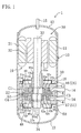
- FIG. 1 is a longitudinal sectional view of a rotary compressor (1) of the present embodiment
- FIG. 2 is a cross-sectional view of a first compression mechanism (20)
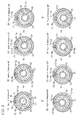
- FIGS. 3 are views illustrating operations of the first compression mechanism (20). Since a second compression mechanism (50) has the same structure as that of the first compression mechanism (20), a cross-sectional view of the second compression mechanism (50) and views illustrating operations thereof will be omitted.
- the first compression mechanism (first eccentric-rotation-type piston mechanism) (20), the second compression mechanism (second eccentric-rotation-type piston mechanism) (50), and an electrical motor (drive mechanism) (30) are accommodated in a casing (10) of the compressor (1), and the compressor (1) is hermetic.
- the compressor (1) is used, e.g., for compressing refrigerant sucked from an evaporator to discharge such refrigerant to a condenser in a refrigerant circuit of an air conditioner.
- the casing (10) includes a cylindrical body (11); an upper end plate (12) fixed to an upper end portion of the body (11); and a lower end plate (13) fixed to a lower end portion of the body (11).
- the body (11) is provided with suction pipes (14) penetrating through the body (11), and the upper end plate (12) is provided with a discharge pipe (15) penetrating through the upper end plate (12).
- the first compression mechanism (20) and the second compression mechanism (50) are stacked in two tiers between a front head (16) and a rear head (17) which are fixed to the casing (10).
- the first compression mechanism (20) is arranged on an electrical motor side (upper side as viewed in FIG. 1 )
- the second compression mechanism (50) is arranged on a bottom side of the casing (10) (lower side as viewed in FIG. 1 ).
- the first compression mechanism (20) includes a first cylinder (21) with first annular cylinder chambers (C1, C2); a first annular piston (22) arranged in the first cylinder chambers (C1, C2); and a first blade (23) dividing the first cylinder chambers (C1, C2) into high-pressure chambers (compression chambers) (C1-Hp, C2-Hp) which are first chambers, and low-pressure chambers (suction chambers) (C1-Lp, C2-Lp) which are second chambers as illustrated in FIGS. 2 and 3 .
- the second compression mechanism (50) has the same structure as that of the first compression mechanism (20), and is vertically flipped with respect to the first compression mechanism (20).
- the second compression mechanism (50) includes a second cylinder (51) with second annular cylinder chambers (C3, C4); a second annular piston (52) arranged in the second cylinder chambers (C3, C4); and a second blade (not shown in the figure) dividing the second cylinder chambers (C3, C4) into high-pressure chambers (not shown in the figure) which are first chambers, and into low-pressure chambers (not shown in the figure) which are second chambers.
- the front head (16) constitutes the first cylinder (21), and the rear head (17) constitutes the second cylinder (51).
- the first cylinder (21) with the first cylinder chambers (C1, C2) and the second cylinder (51) with the second cylinder chambers (C3, C4) are on a fixed side
- the first annular piston (22) and the second annular piston (52) are on a movable side.
- the second annular piston (52) eccentrically rotates with respect to the second cylinder (51).
- a system in which the annular piston (22) is on the movable side as in the present embodiment is hereinafter referred to as a "movable bush system (movable piston system)," whereas a system in which the annular piston (22) is on the fixed side is referred to as a “fixed bush system (fixed piston system).”
- the electrical motor (30) includes a stator (31) and a rotor (32).
- the stator (31) is arranged above the first compression mechanism (20), and is fixed to the body (11) of the casing (10).
- the rotor (32) is connected to a drive shaft (33), and the drive shaft (33) rotates together with the rotor (32).
- the drive shaft (33) vertically penetrates through the first cylinder chambers (C1, C2) and the second cylinder chambers (C3, C4).
- the drive shaft (33) is provided with an oil supply path (not shown in the figure) extending in an axial direction inside the drive shaft (33).
- An oil supply pump (34) is provided in a lower end portion of the drive shaft (33).
- the oil supply path upwardly extends from the oil supply pump (34).
- a first eccentric portion (33a) is formed in a portion of the drive shaft (33), which is positioned in the first cylinder chambers (C1, C2), and a second eccentric portion (63a) is formed in a portion of the drive shaft (33), which is positioned in the second cylinder chambers (C3, C4).
- the first eccentric portion (33a) is formed so that a diameter thereof is larger than that of a portion above the first eccentric portion (33a), and is eccentrically displaced from a shaft center of the drive shaft (33) by a predetermined amount.
- the second eccentric portion (63a) is formed so as to have the same diameter as that of the first eccentric portion (33a), and is eccentrically displaced from the shaft center of the drive shaft (33) by the same amount as that of the first eccentric portion (33a).
- the first eccentric portion (33a) and the second eccentric portion (63a) are 180° out of phase with each other about the shaft center of the drive shaft (33).
- the first annular piston (22) is an integrally-formed member, and includes a first bearing (22a) slidably fitted on the first eccentric portion (33a) of the drive shaft (33); a first annular piston body (22b) positioned on an outer circumferential side of the first bearing (22a) so as to be concentric with the first bearing (22a); and a first piston-side end plate (22c) connecting the first bearing (22a) to the first annular piston body (22b).
- the first annular piston body (22b) is formed in a C-shape, i.e., a part of the annular ring splits.
- the second annular piston (52) is an integrally-formed member, and includes a second bearing (52a) slidably fitted on the second eccentric portion (63a) of the drive shaft (33); a second annular piston body (52b) positioned on an outer circumferential side of the second bearing (52a) so as to be concentric with the second bearing (52a); and a second piston-side end plate (52c) connecting the second bearing (52a) to the second annular piston body (52b).
- the second annular piston body (52b) is formed in a C-shape, i.e., a part of the annular ring splits.
- the first cylinder (21) includes a first inner cylinder portion (21b) positioned between the first bearing (22a) and the first annular piston body (22b) so as to be concentric with the drive shaft (33); a first outer cylinder portion (21a) positioned on an outer circumferential side of the first annular piston body (22b) so as to be concentric with the first inner cylinder portion (21b); and a first cylinder-side end plate (21 c) connecting the first inner cylinder portion (21 b) to the first outer cylinder portion (21a).
- the second cylinder (51) includes a second inner cylinder portion (51b) positioned between the second bearing (52a) and the second annular piston body (52b) so as to be concentric with the drive shaft (33); a second outer cylinder portion (51a) positioned on an outer circumferential side of the second annular piston body (52b) so as to be concentric with the second inner cylinder portion (51b); and a second cylinder-side end plate (5 1 c) connecting the second inner cylinder portion (51b) to the second outer cylinder portion (51a).
- the front head (16) and the rear head (17) are provided with bearings (16a, 17a) for supporting the drive shaft (33), respectively.
- the compressor (1) of the present embodiment has a penetrating shaft structure in which the drive shaft (33) vertically penetrates through the first cylinder chambers (C1, C2) and the second cylinder chambers (C3, C4), and in which portions on both sides of the first eccentric portion (33a) and of the second eccentric portion (63a) in the axial direction are held by the casing (10) with the bearings (16a, 17a).
- first and second compression mechanisms (20, 50) will be described. As described above, since the compression mechanisms (20, 50) have the same structure, the first compression mechanism (20) will be described as a representative example.
- the first compression mechanism (20) includes first swing bushes (27) as connecting members for connecting the first annular piston (22) to the first blade (23) at the split portion of the first annular piston (22) so as to be capable of swinging.
- the first blade (23) extends from a wall surface on an inner circumferential side of the first cylinder chambers (C1, C2) (an outer circumferential surface of the first inner cylinder portion (21b)) to a wall surface on an outer circumferential side (an inner circumferential surface of the first outer cylinder portion (21a)) in a radial direction of the first cylinder chambers (C1, C2) with the first blade (23) penetrating through the split portion of the first annular piston (22).
- the first blade (23) is fixed to the first outer cylinder portion (21a) and the first inner cylinder portion (21 b).
- the first blade (23) may be integrally formed with the first outer cylinder portion (21a) and the first inner cylinder portion (21 b), or another member may be attached to the both cylinder portions (21a, 21 b).
- FIG. 2 illustrates an example of fixing another member to the both cylinder portions (21a, 21 b).
- the inner circumferential surface of the first outer cylinder portion (21a) and the outer circumferential surface of the first inner cylinder portion (21 b) are cylindrical surfaces arranged so as to be concentric with each other, and the first cylinder chambers (C1, C2) are formed therebetween.
- a diameter of an outer circumferential surface of the first annular piston (22) is smaller than that of the inner circumferential surface of the first outer cylinder portion (21a), and a diameter of an inner circumferential surface of the first annular piston (22) is larger than that of the outer circumferential surface of the first inner cylinder portion (21b).
- the first outer cylinder chamber (C1) is defined by the first cylinder-side end plate (21 c), the first piston-side end plate (22c), the first outer cylinder portion (21a), and the first annular piston body (22b); and the first inner cylinder chamber (C2) is defined by the first cylinder-side end plate (21c), the first piston-side end plate (22c), the first inner cylinder portion (21b), and the first annular piston body (22b).
- an operation space (25) for allowing the first bearing (22a) to eccentrically rotate on an inner circumferential side of the first inner cylinder portion (21b) is defined by the first cylinder-side end plate (21c), the first piston-side end plate (22c), the first bearing (22a) of the first annular piston (22), and the first inner cylinder portion (21 b).
- the inner circumferential surface of the first annular piston (22) substantially contacts the outer circumferential surface of the first inner cylinder portion (21a) at one point (i.e., a state in which, even if there is a micron-order space, no disadvantage is caused due to refrigerant leakage in such a space)
- the inner circumferential surface of the first annular piston (22) substantially contacts the outer circumferential surface of the first inner cylinder portion (21b) at one point which is 180° out of phase with the above-described contact point.
- the first swing bushes (27) are constituted by a discharge-side bush (27A) positioned on a high-pressure chamber (C1-Hp, C2-Hp) side with respect to the first blade (23); and a suction-side bush (27B) positioned on a low-pressure chamber (C1-Lp, C2-Lp) side with respect to the first blade (23).
- the discharge-side bush (27A) and the suction-side bush (27B) are formed in the same shape which is an approximately-semicircular cross-sectional shape, and flat planes thereof are arranged so as to face to each other.
- a blade groove (28) is defined by a space between the planes of the bushes (27A, 27B) facing to each other.
- the first blade (23) is inserted into the blade groove (28).
- the flat planes of the first swing bushes (27A, 27B) substantially contact the first blade (23), and arc-like outer circumferential surfaces of the first swing bushes (27A, 27B) substantially contact the first annular piston (22).
- the first swing bushes (27A, 27B) move back and forth in a plane direction of the first blade (23) with the first blade (23) being inserted into the blade groove (28).
- the first swing bushes (27A, 27B) allow the first annular piston (22) to swing with respect to the first blade (23).
- the first swing bushes (27) are configured so that the first annular piston (22) can swing with respect to the first blade (23) about a center point between the first swing bushes (27) as a swing center, and so that the first annular piston (22) can move back and forth along the first blade (23) in the plane direction thereof.
- both bushes (27A, 27B) are separate members.
- portions of the both bushes (27A, 27B) may be connected to each other, thereby forming the integrated member.
- the first annular piston (22) swings about the center point between the first swing bushes (27) as the swing center while the first swing bushes (27) move back and forth along the first blade (23).
- the second annular piston (52) also swings about a center point between second swing bushes (not shown in the figure) as a swing center in the same manner as the first annular piston (22).
- Such swing makes a first contact point between the first annular piston (22) and the first cylinder (21) sequentially move from a state illustrated in FIG. 3(A) to a state illustrated in FIG. 3(H) .
- a second contact point between the second annular piston (52) and the second cylinder (51) is displaced from the first contact point by 180° about the shaft center of the drive shaft (33). That is, as viewed from above the drive shaft (33), when the first compression mechanism (20) is in an operation illustrated in FIG. 3(A) , the second compression mechanism (50) is in an operation illustrated in FIG. 3(E) .
- FIGS. 3 are views illustrating operations of the first compression mechanism (20) in the movable bush system
- FIGS. 3(A)-3(H) illustrate states in which the first annular piston (22) moves at 45° interval in a clockwise direction as viewed in the figures.
- the first annular piston (22) swings and revolves about the drive shaft (33), but the first annular piston (22) itself does not rotate.
- a suction port (41) to which the suction pipe (14) is connected is formed so as to communicate with the low-pressure chamber (C1-Lp) of the first outer cylinder chamber (C1).
- a through-hole (44) for communicating the low-pressure chamber (C1-Lp) of the first outer cylinder chamber (C1) with the low-pressure chamber (C2-Lp) of the first inner cylinder chamber (C2) is formed in the first annular piston (22).
- a suction port (41) to which the suction pipe (14) is connected is also formed in the rear head (17) so as to communicate with the low-pressure chamber of the second outer cylinder chamber (C3).
- a through-hole (44) for communicating the low-pressure chamber of the second outer cylinder chamber (C3) with the low-pressure chamber of the first inner cylinder chamber (C2) is formed in the second annular piston (52).
- a first outer discharge port (45) and a first inner discharge port (46) are formed in the front head (16).
- the discharge ports (45, 46) penetrate through the first cylinder-side end plate (21c) of the front head (16) in the axial direction thereof.
- a lower end of the first outer discharge port (45) opens so as to face to the high-pressure chamber (C1-Hp) of the first outer cylinder chamber (C1), and a lower end of the first inner discharge port (46) opens so as to face to the high-pressure chamber (C2-Hp) of the first inner cylinder chamber (C2).
- upper ends of the discharge ports (45, 46) communicate with a discharge space (49) through a discharge valve (not shown in the figure) for opening/closing the discharge ports (45, 46).
- a second outer discharge port (not shown in the figure) and a second inner discharge port (not shown in the figure) are also formed in the rear head (17).
- Such discharge ports penetrate through the second cylinder-side end plate (51c) of the rear head (17) in the axial direction thereof.
- a lower end of the second outer discharge port opens so as to face to the high-pressure chamber of the second outer cylinder chamber (C3), and a lower end of the second inner discharge port opens so as to face to the high-pressure chamber of the second inner cylinder chamber (C4).
- Upper ends of the discharge ports communicate with a discharge space (49) through a discharge valve (not shown in the figure) for opening/closing the discharge ports.
- the discharge spaces (49) are formed between the front head (16) and a first cover member (18); and between the rear head (17) and a second cover member (48).
- the first cover member (18) functions as a muffler mechanism in which, after gas discharged from the first compression mechanism (20) is temporarily discharged to the discharge space (49), such gas flows out to a high-pressure space (19) in the casing (10) through a discharge opening (18a) between the first cover member (18) and the bearing (16a), thereby muffling noise.
- the second cover member (48) also functions as a muffler mechanism in which, after gas discharged from the second compression mechanism (50) is temporarily discharged to the discharge space (49), such gas flows out to a high-pressure space (19) in the casing (10) through a discharge opening (48a) between the second cover member (48) and the bearing (17a), thereby muffling noise.
- the first and second compression mechanisms (20, 50) are operated 180° out of phase with each other. Since the operations of the first and second compression mechanisms (20, 50) are the same except for their phases, the operation of the first compression mechanism (20) will be described as a representative example.
- the rotation of the rotor (32) is conveyed to the first annular piston (22) of the first compression mechanism (20) through the drive shaft (33).
- the first swing bushes (27A, 27B) reciprocate (move back and forth) along the first blade (23), and the first annular piston (22) and the first swing bushes (27A, 27B) swing with respect to the first blade (23) in an integrated manner.
- the surfaces of the first swing bushes (27A, 27B) substantially contact the first annular piston (22) and the first blade (23).
- the first annular piston (22) swings and revolves with respect to the first outer cylinder portion (21a) and the first inner cylinder portion (21b), thereby performing a predetermined compression operation by the first compression mechanism (20).
- the volume of a low-pressure chamber (C1-Lp) is approximately minimum in the state illustrated in FIG. 3(B) .
- the volume of the low-pressure chamber (C1-Lp) increases as the state illustrated in FIG. 3(C) is sequentially changed to the state illustrated in FIG. 3(A) by rotating the drive shaft (33) clockwise as viewed in the figure, refrigerant is sucked into the low-pressure chamber (C1-Lp) through the suction pipe (14) and the suction port (41).
- the suction of the refrigerant into the low-pressure chamber (C1-Lp) is completed.
- the low-pressure chamber (C1-Lp) is changed to a high-pressure chamber (C1-Hp) in which the refrigerant is compressed, and another low-pressure chamber (C1-Lp) is formed across the first blade (23).
- the suction of the refrigerant is repeated in the low-pressure chamber (C1-Lp), and the volume of the high-pressure chamber (C1-Hp) decreases to compress the refrigerant in the high-pressure chamber (C1-Hp).
- the discharge valve When a pressure in the high-pressure chamber (C1-Hp) reaches a predetermined value, and a pressure difference between the high-pressure chamber (C1-Hp) and the discharge space (49) reaches a set value, the discharge valve is opened by the high-pressure refrigerant of the high-pressure chamber (C1-Hp), thereby flowing out the high-pressure refrigerant from the discharge space (49) to the high-pressure space (19) of the casing (10) through the discharge opening (18a).
- the volume of a low-pressure chamber (C2-Lp) is approximately minimum in the state illustrated in FIG. 3(F) .
- the volume of the low-pressure chamber (C2-Lp) increases as the state illustrated in FIG. 3(G) is sequentially changed to the state illustrated in FIG. 3(E) by rotating the drive shaft (33) clockwise as viewed in the figure, refrigerant is sucked into the low-pressure chamber (C2-Lp) of the first inner cylinder chamber (C2) through the suction pipe (14), the suction port (41), and the through-hole (44).
- the suction of the refrigerant into the low-pressure chamber (C2-Lp) is completed.
- the low-pressure chamber (C2-Lp) is changed to a high-pressure chamber (C2-Hp) in which the refrigerant is compressed, and another low-pressure chamber (C2-Lp) is formed across the first blade (23).
- the suction of the refrigerant is repeated in the low-pressure chamber (C2-Lp), and the volume of the high-pressure chamber (C2-Hp) decreases to compress the refrigerant in the high-pressure chamber (C2-Hp).
- the discharge valve When a pressure in the high-pressure chamber (C2-Hp) reaches a predetermined value, and a pressure difference between the high-pressure chamber (C2-Hp) and the discharge space (49) reaches a set value, the discharge valve is opened by the high-pressure refrigerant of the high-pressure chamber (C2-Hp), thereby flowing out the high-pressure refrigerant from the discharge space (49) to the high-pressure space (19) of the casing (10) through the discharge opening (18a).
- the discharge of the refrigerant is started at a timing at which the compression mechanism is approximately in the state illustrated in FIG. 3(E) ; and, in the first inner cylinder chamber (C2), the discharge is started at a timing at which the compression mechanism is approximately in the state illustrated in FIG. 3(A) . That is, the first outer cylinder chamber (C1) and the first inner cylinder chamber (C2) differ from each other in the discharge timing by approximately 180°.
- the high-pressure refrigerant which is compressed in the first outer cylinder chamber (C1) and the first inner cylinder chamber (C2) to flow out to the high-pressure space (19) of the casing (10) is discharged through the discharge pipe (15), and then such refrigerant is sucked into the compressor (1) again after condensation, expansion, and evaporation strokes in the refrigerant circuit.
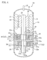
- FIGS. 4-6 A compressor of a comparative example illustrated in FIGS. 4-6 will be briefly described.
- FIGS. 1-3 employs the movable bush system in which the first annular piston (22) is on the movable side, whereas compression mechanisms of a compressor (70) of the comparative example employs the fixed bush system in which a first annular piston (22) is on the fixed side.
- compression mechanisms of a compressor (70) of the comparative example employs the fixed bush system in which a first annular piston (22) is on the fixed side.
- a first compression mechanism (20) and a second compression mechanism (50) are arranged between a front head (16) and a rear head (17) which are fixed to a casing (10) in the similar manner to that of the example illustrated in FIGS. 1-3 .
- the first compression mechanism (20) is arranged on an electrical motor side (upper side as viewed in FIG. 4 ), and the second compression mechanism (50) is arranged on a bottom side of the casing (10) (lower side as viewed in FIG. 4 ).
- the first compression mechanism (20) includes a first cylinder (21) with first annular cylinder chambers (C1, C2); a first annular piston (22) arranged in the first cylinder chambers (C1, C2); and a first blade (23) dividing the first cylinder chambers (C1, C2) into high-pressure chambers (compression chambers) (C1-Hp, C2-Hp) which are first chambers, and low-pressure chambers (suction chambers) (C1-Lp, C2-Lp) which are second chambers.
- the second compression mechanism (50) has the same structure as that of the first compression mechanism (20), and is vertically flipped with respect to the first compression mechanism (20).
- the second compression mechanism (50) includes a second cylinder (51) with second annular cylinder chambers (C3, C4); a second annular piston (52) arranged in the second cylinder chambers (C3, C4); and a second blade (not shown in the figure) dividing the second cylinder chambers (C3, C4) into high-pressure chambers (not shown in the figure) which are first chambers, and low-pressure chambers (not shown in the figure) which are second chambers.
- the first cylinder (21) eccentrically rotates with respect to the first annular piston (22). That is, in the present example, the first cylinder (21) with the first cylinder chambers (C1, C2) is on the movable side, and the first annular piston (22) arranged in the first cylinder chambers (C1, C2) is on the fixed side.
- the second cylinder (51) eccentrically rotates with respect to the second annular piston (52). That is, in the present example, the second cylinder (51) with the second cylinder chambers (C3, C4) is on the movable side, and the second annular piston (52) arranged in the second cylinder chambers (C3, C4) is on the fixed side.
- the first cylinder (21) includes a first outer cylinder portion (21a) and a first inner cylinder portion (21b).
- the first outer cylinder portion (21a) and the first inner cylinder portion (21b) are integrated by connecting to each other through a first cylinder-side end plate (21 c) at lower end portions thereof.
- the first inner cylinder portion (21 b) is slidably fitted on a first eccentric portion (33a) of a drive shaft (33).
- the second cylinder (51) includes a second outer cylinder portion (51 a) and a second inner cylinder portion (51 b).
- the second outer cylinder portion (51a) and the second inner cylinder portion (51b) are integrated by connecting to each other through a second cylinder-side end plate (51c) at upper end portions thereof.
- the second inner cylinder portion (51b) is slidably fitted on a second eccentric portion (63a) of the drive shaft (33).
- the first annular piston (22) is constituted by the front head (16), and has a structure in which the first annular piston body (22b) is integrally formed with the first piston-side end plate (22c) at an upper end portion thereof.
- the second annular piston (52) is constituted by the rear head (17), and has a structure in which the second annular piston body (52b) is integrally formed with the second piston-side end plate (52c) at a lower end portion thereof.
- the comparative example is similar to the example illustrated in FIGS. 1-3 in that a first outer cylinder chamber (C1) is defined by the first cylinder-side end plate (21 c), the first piston-side end plate (22c), the first outer cylinder portion (21a), and the first annular piston body (22b); and that a first inner cylinder chamber (C2) is defined by the first cylinder-side end plate (21 c), the first piston-side end plate (22c), the first inner cylinder portion (21 b), and the first annular piston body (22b).
- the comparative example is similar to the example illustrated in FIGS. 1-3 in that a second outer cylinder chamber (C3) is defined by the second cylinder-side end plate (51c), the second piston-side end plate (52c), the second outer cylinder portion (51a), and the second annular piston body (52b); and that a second inner cylinder chamber (C4) is defined by the second cylinder-side end plate (51c), the second piston-side end plate (52c), the second inner cylinder portion (51b), and the second annular piston body (52b).
- a second outer cylinder chamber (C3) is defined by the second cylinder-side end plate (51c), the second piston-side end plate (52c), the second outer cylinder portion (51a), and the second annular piston body (52b)
- a second inner cylinder chamber (C4) is defined by the second cylinder-side end plate (51c), the second piston-side end plate (52c), the second inner cylinder portion (51b), and the second annular piston body (52b).
- an operation space (26) for allowing the first outer cylinder portion (21a) to eccentrically rotate is formed in the front head (16), and an operation space (26) for allowing the second outer cylinder portion (51a) to eccentrically rotate is formed in the rear head (17).
- the operation spaces (26) are low-pressure spaces communicating with suction pipes (14), through-holes (44a, 44b) for sucking low-pressure gas from such low-pressure operation spaces (26) are formed in the first and second outer cylinder portions (21a, 51a) and the first and second inner cylinder portions (21 b, 51 b), respectively.
- first and second compression mechanisms (20, 50) will be described. Since the compression mechanisms (20, 50) have the same structure as described above, the first compression mechanism (20) will be described as a representative example.
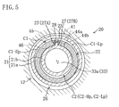
- first swing bushes (27A, 27B) are configured so that the first blade (23) moves back and forth in a blade groove (28) in a plane direction of the first blade (23) with the first blade (23) being inserted into the blade groove (28) as illustrated in FIG. 5 .
- the first swing bushes (27A, 27B) allow the first blade (23) to swing with respect to the first annular piston (22).
- the first swing bushes (27) are configured so that the first blade (23) can swing with respect to the first annular piston (22) about a center point between the first swing bushes (27) as a swing center, and that the first blade (23) can move back and forth with respect to the first annular piston (22) in the plane direction of the first blade (23).
- the first outer cylinder portion (21a) and the first inner cylinder portion (21 b) swing about the center point between the first swing bushes (27) as the swing center while the first blade (23) moves back and forth in the blade groove (28).
- the second outer cylinder portion (51a) and the second inner cylinder portion (51b) also swing about a center point between second swing bushes (not shown in the figure) as a swing center while a second blade (not shown in the figure) moves back and forth in a second blade groove (not shown in the figure), in the same manner as the first outer cylinder portion (21a) and the first inner cylinder portion (21 b).
- Such swing makes a first contact point between the first annular piston (22) and the first cylinder (21) sequentially move from a state illustrated in FIG. 6(A) to a state illustrated in FIG. 6(H) .
- a second contact point between the second annular piston (52) and the second cylinder (51) is displaced from the first contact point by 180° about a shaft center of the drive shaft (33). That is, as viewed from above the drive shaft (33), when the first compression mechanism (20) is in an operation illustrated in FIG. 6(A) , the second compression mechanism (50) is in an operation illustrated in FIG. 6(E) .
- FIGS. 6 are views illustrating operations of the first compression mechanism (20) in the fixed bush system
- FIGS. 6(A)-6(H) illustrate states in which the first cylinder (21) moves at 45° interval in a clockwise direction as viewed in the figures.
- the first outer cylinder portion (21a) and the first inner cylinder portion (21 b) swing and revolve about the drive shaft (33), but the first outer cylinder portion (21a) and the first inner cylinder portion (21b) themselves do not rotate. Since other structures are similar to those of the example illustrated in FIGS. 1-3 , description thereof will not be repeated.
- the first and second compression mechanisms (20, 50) are operated 180° out of phase with each other. Since the operations of the first and second compression mechanisms (20, 50) are the same except for their phases, the operation of the first compression mechanism (20) will be described as a representative example.
- the volume of a low-pressure chamber (C1-Lp) is approximately minimum in the state illustrated in FIG. 6(F) .
- the volume of the low-pressure chamber (C1-Lp) increases as the state illustrated in FIG. 6(G) is sequentially changed to the state illustrated in FIG. 6(E) by rotating the drive shaft (33) clockwise as viewed in the figure, refrigerant is sucked into the low-pressure chamber (C1-Lp) through the suction pipe (14), the operation space (26), and the through-hole (44a).
- the suction of the refrigerant into the low-pressure chamber (C1-Lp) is completed.
- the low-pressure chamber (C1-Lp) is changed to a high-pressure chamber (C1-Hp) in which the refrigerant is compressed, and another low-pressure chamber (C1-Lp) is formed across the first blade (23).
- the suction of the refrigerant is repeated in the low-pressure chamber (C1-Lp), and the volume of the high-pressure chamber (C1-Hp) decreases to compress the refrigerant in the high-pressure chamber (C1-Hp).
- a discharge valve is opened by the high-pressure refrigerant of the high-pressure chamber (C1-Hp), thereby flowing out the high-pressure refrigerant from the discharge space (49) to a high-pressure space (19) of the casing (10) through a discharge opening (18a).
- the volume of a low-pressure chamber (C2-Lp) is approximately minimum in the state illustrated in FIG. 6(B) .
- the volume of the low-pressure chamber (C2-Lp) increases as the state illustrated in FIG. 6(C) is sequentially changed to the state illustrated in FIG. 6(A) by rotating the drive shaft (33) clockwise as viewed in the figure, refrigerant is sucked into the low-pressure chamber (C2-Lp) through the suction pipe (14), the operation space (26), the through-hole (44a), the low-pressure chamber (C1-Lp) of the first outer cylinder chamber (C1), and the through-hole (44b).
- the suction of the refrigerant into the low-pressure chamber (C2-Lp) is completed.
- the low-pressure chamber (C2-Lp) is changed to a high-pressure chamber (C2-Hp) in which the refrigerant is compressed, and another low-pressure chamber (C2-Lp) is formed across the first blade (23).
- the suction of the refrigerant is repeated in the low-pressure chamber (C2-Lp), and the volume of the high-pressure chamber (C2-Hp) decreases to compress the refrigerant in the high-pressure chamber (C2-Hp).
- a discharge valve is opened by the high-pressure refrigerant of the high-pressure chamber (C2-Hp), thereby flowing out the high-pressure refrigerant from the discharge space (49) to the high-pressure space (19) of the casing (10) through the discharge opening (18a).
- the discharge of the refrigerant is started at a timing at which the compression mechanism is approximately in the state illustrated in FIG. 6(A) ; and, in the first inner cylinder chamber (C2), the discharge is started at a timing at which the compression mechanism is approximately in the state illustrated in FIG. 6(E) . That is, the first outer cylinder chamber (C1) and the first inner cylinder chamber (C2) differ from each other in the discharge timing by approximately 180°.
- the high-pressure refrigerant which is compressed in the first outer cylinder chamber (C1) and the first inner cylinder chamber (C2) to flow out to the high-pressure space (19) of the casing (10) is discharged through a discharge pipe (15), and then such refrigerant is sucked into the compressor (1) again after condensation, expansion, and evaporation strokes in the refrigerant circuit.
- the "swing moment” is a force which acts on an object swinging about a pivot point such as pendulums, and is represented by a product of a moment of inertia and a swing angular acceleration about the pivot point of the object.
- a reaction force of the swing moment acts on the pivot point.
- FIG. 7 illustrates a swing moment caused in the compression mechanism when an angle of rotation ( ⁇ ) of the drive shaft is 315° in the fixed bush system
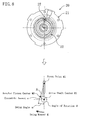
- FIG. 8 illustrates a swing moment caused in the compression mechanism when an angle of rotation ( ⁇ ) of the drive shaft is 315° in the movable bush system.
- the "angle of rotation ( ⁇ )” indicates a rotation angle of the drive shaft about a drive shaft center (M2)
- a “swing angle ( ⁇ )” indicates a revolution angle of a swing member (cylinder in the fixed bush system, or piston in the movable bush system) about a pivot point (M1).
- the pivot point (M1) is positioned at the center between the swing bushes (27).
- An size of a shaded area (A) schematically illustrates the swing moment caused in the swing member.
- the swing moment is caused in the cylinder (21, 51) swinging about the center between the fixed swing bushes (27).
- a reaction force of such a swing moment acts on the swing bushes (27) having the pivot point (M1).
- the reaction force acting on the swing bushes (27) is conveyed to the casing (10) to which the annular pistons (22, 52) are fixed, through the annular piston (22, 52), thereby vibrating the compressor (70).
- FIGS. 9 illustrate swing moments in the fixed bush system
- FIG. 9(A) illustrates the swing moment in the first compression mechanism (20) arranged on the upper side
- FIG. 9(B) illustrates the swing moment in the second compression mechanism (50) arranged on the lower side
- FIGS. 10 illustrate swing moments in the movable bush system
- FIG. 10(A) illustrates the swing moment in the first compression mechanism (20) arranged on the upper side
- FIG. 10(B) illustrates the swing moment in the second compression mechanism (50) arranged on the lower side.
- the sizes of the areas (A), i.e., the swing moments may be different in the first compression mechanism (20) and the second compression mechanism (50) at an arbitrary angle of rotation ( ⁇ ).
- the sizes of the areas (A) are different from each other because distances between the pivot points (M1) and cylinder centers (M3) are different in the first compression mechanism (20) and the second compression mechanism (50) at the arbitrary angle of rotation ( ⁇ ).
- the sizes of the areas (A), i.e., the swing moments are the same in the first compression mechanism (20) and the second compression mechanism (50) at an arbitrary angle of rotation ( ⁇ ).
- the sizes of the areas (A) are the same because distances between the pivot points (M1) and annular piston centers (M3) are the same in the first compression mechanism (20) and the second compression mechanism (50) at the arbitrary angle of rotation ( ⁇ ).
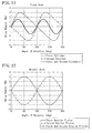
- FIG. 11 is a plot illustrating relationships between the swing moments and the angles of rotation of the drive shaft in the compressor (70) in which the compression mechanisms employing the fixed bush system are stacked in two tiers; and FIG. 12 is a plot illustrating relationships between the swing moments and the angles of rotation of the drive shaft in the compressor (1) in which the compression mechanisms employing the movable bush system are stacked in two tiers.
- Solid lines in FIGS. 11 and 12 represent swing moments when the swing moment of one compression mechanism is superposed on the swing moment of the other compression mechanism.
- the swing moments caused in the first compression mechanism (20) and the second compression mechanism (50) are different from each other at the arbitrary angle of rotation ( ⁇ ).
- the compression mechanisms are arranged so as to be operated 180° out of phase with each other, the swing moments may not cancel out each other, thereby conveying the reaction force of the swing moments which have not cancelled out each other, to the compressor.
- the swing moments caused in the first compression mechanism (20) and the second compression mechanism (50) is the same at the arbitrary angle of rotation ( ⁇ ). That is, if the first compression mechanism (20) and the second compression mechanism (50) are constituted by the same components, magnitudes of the swing moments of the compression mechanisms (20, 50) are the same. Thus, if the compression mechanisms are arranged so as to be operated 180° out of phase with each other, the swing moments cancel out each other, resulting in a zero swing moment conveyed to the compressor (1).
- the first and second compression mechanisms (20, 50) employ the movable system and have the same structure (the same shape and dimension), except that the first eccentric portion (33a) and the second eccentric portion (63a) are 180° out of phase with each other about the shaft center of the drive shaft (33).
- the swing moments caused in the compression mechanisms can cancel out each other. Consequently, in the compressor (1), vibration due to the swing moments in the first and second compression mechanisms (20, 50) can be reduced.
- the force acts in a direction in which the swing moments of the compression mechanisms (20, 50) cancels out each other, by employing the movable bush system, thereby reducing the swing moment of the compressor (1).
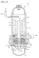
- Embodiment 2 of the present invention will be described.
- Embodiment 2 uses carbon dioxide as refrigerant (working fluid) of a compressor (1), and is an example of two-stage compression mechanisms in which the refrigerant is compressed in two stages in a first compression mechanism (20) and a second compression mechanism (50).
- the compressor (1) includes the first compression mechanism (20) and the second compression mechanism (50) which employ the movable bush system.
- the second compression mechanism (50) is a lower-stage compression mechanism
- the first compression mechanism (20) is a higher-stage compression mechanism.
- the second compression mechanism (50) includes a first suction pipe (14a) for sucking low-pressure refrigerant, and a first discharge pipe (15a) for discharging intermediate-pressure refrigerant.
- the first suction pipe (14a) is fixed to a rear head (17), and communicates with cylinder chambers (C3, C4) of the second compression mechanism (50).
- An intermediate discharge space (17b) communicating with the cylinder chambers (C3, C4) of the second compression mechanism (50) is formed in the rear head (17).
- the intermediate-pressure refrigerant compressed in the second compression mechanism (50) is discharged to the intermediate discharge space (17b) through a discharge port and a discharge valve (not shown in the figure).
- the first discharge pipe (15a) penetrating through a body (11) of a casing (10) is fixed to the rear head (17).
- An inner end portion of the first discharge pipe (15a) opens to the intermediate discharge space (17b) of the rear head (17), and an outer end portion is connected to an intermediate-pressure refrigerant pipe (not shown in the figure) in a refrigerant circuit.
- the first compression mechanism (20) includes a second suction pipe (14b) for sucking intermediate-pressure refrigerant.
- the second suction pipe (14b) is fixed to a front head (16), and communicates with cylinder chambers (C1, C2) of the first compression mechanism (20).
- the second suction pipe (14b) is connected to an injection pipe (14c) for injecting the intermediate-pressure refrigerant to the first compression mechanism (20).
- High-pressure refrigerant compressed in the cylinder chambers (C1, C2) of the first compression mechanism (20) is discharged to a discharge space (49) through a discharge port and a discharge valve (not shown in the figure), and then such refrigerant flows out from the discharge space (49) to a high-pressure space (19) of the casing (10).
- the high-pressure refrigerant filling the casing (10) is discharged to a high-pressure gas pipe of the refrigerant circuit through a second discharge pipe (15b) provided in an upper portion of the casing (10).
- the two-stage compression mechanisms are constituted by the first compression mechanism (20) and the second compression mechanism (50), and the cylinder volume of the first compression mechanism (20) in the higher stage is smaller than that of the second compression mechanism (50) in the lower stage.
- a length L1 of a first annular piston body (22b) in the axial direction is shorter than a length L2 of a second annular piston body (52b) in the axial direction.
- a thickness t1 of a first piston-side end plate (22c) is thicker than a thickness t2 of a second piston-side end plate (52c). This makes a magnitude of a swing moment caused in the first compression mechanism (20) equal to that of a swing moment caused in the second compression mechanism (50).
- the swing moment is a value proportional to an expression "a piston inertia moment x e (eccentric amount in FIG. 8 ) / L (distance between the pivot point (M1) and the annular piston center (M3) in FIG. 8 )." If the moments of inertia of the piston bodies of the first compression mechanism (20) and of the second compression mechanism (50) are different from each other, the swing moments can be equalized by adjusting the moment of inertia of the piston end plate portion, the size of "e,” or the size of "L.”
- Embodiment 2 Other structures of Embodiment 2 are similar to those of Embodiment 1, including that a first eccentric portion (33a) and a second eccentric portion (63a) are 180° out of phase with each other about a shaft center of a drive shaft (33).
- the length of the first annular piston body (22b) in the axial direction is shorter than that of the second annular piston body (52b) in the axial direction, and the thickness of the first piston-side end plate (22c) is thicker than that of the second piston-side end plate (52c). Consequently, the magnitudes of the swing moments are equalized between the first compression mechanism (20) and the second compression mechanism (50).
- the length of the first annular piston body (22b) in the axial direction is shorter than that of the second annular piston body (52b) in the axial direction, thereby making the cylinder volumes of the first compression mechanism (20) and of the second compression mechanism (50) different from each other.
- the cylinder volumes may be adjusted by changing a diameter of the first annular piston body (22b) or of the second annular piston body (52b).
- the two-stage compression mechanisms are employed, in which the cylinder volume of the first compression mechanism (20) is smaller than that of the second compression mechanism (50).
- a structure may be employed, in which, by increasing an injection amount of intermediate-pressure refrigerant, the cylinder volume of the first compression mechanism (20) becomes equal to that of the second compression mechanism (50), or the cylinder volume of the first compression mechanism (20) becomes larger than that of the second compression mechanism (50). If the cylinder volumes of the both compression mechanisms (20, 50) are the same, components having the same structure (the same shape and dimension) may be used for the compression mechanisms (20, 50).
- the length of the first annular piston body (22b) in the axial direction may be longer than that of the second annular piston body (52b) in the axial direction, and the thickness of the first piston-side end plate (22c) may be thinner than that of the second piston-side end plate (52c).
- the eccentric-rotation-type piston mechanisms are constituted by the compression mechanisms.
- such mechanisms may be constituted by, e.g., expansion mechanisms.
- the first eccentric portion (33a) and the second eccentric portion (63a) are 180° out of phase with each other about the shaft center of the drive shaft (33).
- an advantageous range of a phase difference in the fixed bush system may be, e.g., 180 ⁇ 15°.
- the first and second compression mechanisms (20, 50) have the same structure (i.e., a shape ratio of the second annular piston (52) to the first annular piston (22) is "1"), except that there is the phase difference between the first eccentric portion (33a) and the second eccentric portion (63a).
- a shape ratio may be changed within the advantageous range in the fixed bush system. If changing the shape ratio, it is preferred that an inertia moment ratio or an e (eccentric amount in FIG. 8 ) / L (distance between the pivot point (M1) and the annular piston center (M3) in FIG. 8 ) ratio is changed, and each of the inertia moment ratio and the e/L ratio may be changed within a range of 0.74-1.26.
- the present invention is useful for a rotary fluid machine in which eccentric-rotation-type piston mechanisms including cylinders with annular cylinder chambers, and annular pistons eccentrically accommodated in the cylinder chambers are stacked in two tiers.
Landscapes
- Engineering & Computer Science (AREA)
- Mechanical Engineering (AREA)
- General Engineering & Computer Science (AREA)
- Applications Or Details Of Rotary Compressors (AREA)
Applications Claiming Priority (2)
| Application Number | Priority Date | Filing Date | Title |
|---|---|---|---|
| JP2007238846 | 2007-09-14 | ||
| PCT/JP2008/002532 WO2009034717A1 (fr) | 2007-09-14 | 2008-09-12 | Machine rotative à fluide |
Publications (2)
| Publication Number | Publication Date |
|---|---|
| EP2196677A1 true EP2196677A1 (fr) | 2010-06-16 |
| EP2196677A4 EP2196677A4 (fr) | 2015-01-14 |
Family
ID=40451736
Family Applications (1)
| Application Number | Title | Priority Date | Filing Date |
|---|---|---|---|
| EP08831266.5A Withdrawn EP2196677A4 (fr) | 2007-09-14 | 2008-09-12 | Machine rotative à fluide |
Country Status (3)
| Country | Link |
|---|---|
| EP (1) | EP2196677A4 (fr) |
| JP (1) | JP4438886B2 (fr) |
| WO (1) | WO2009034717A1 (fr) |
Cited By (1)
| Publication number | Priority date | Publication date | Assignee | Title |
|---|---|---|---|---|
| CN111005871A (zh) * | 2019-12-11 | 2020-04-14 | 珠海格力电器股份有限公司 | 压缩机并联系统的减振方法 |
Families Citing this family (2)
| Publication number | Priority date | Publication date | Assignee | Title |
|---|---|---|---|---|
| JP5521470B2 (ja) * | 2009-09-30 | 2014-06-11 | ダイキン工業株式会社 | 回転式流体機械 |
| JP6324859B2 (ja) * | 2014-09-26 | 2018-05-16 | 株式会社イワキ | 容積型ポンプ |
Citations (1)
| Publication number | Priority date | Publication date | Assignee | Title |
|---|---|---|---|---|
| WO2007102496A1 (fr) * | 2006-03-09 | 2007-09-13 | Daikin Industries, Ltd. | Dispositif de congelation |
Family Cites Families (9)
| Publication number | Priority date | Publication date | Assignee | Title |
|---|---|---|---|---|
| JPS61151090U (fr) * | 1985-03-13 | 1986-09-18 | ||
| JPS6410066U (fr) | 1987-07-03 | 1989-01-19 | ||
| JP2915110B2 (ja) * | 1990-08-20 | 1999-07-05 | 株式会社日立製作所 | スクロール流体機械 |
| JPH05187374A (ja) * | 1992-01-13 | 1993-07-27 | Sanyo Electric Co Ltd | 密閉型圧縮機 |
| JP3016113B2 (ja) * | 1994-06-17 | 2000-03-06 | 株式会社アスカジャパン | スクロール型流体機械 |
| JPH11230073A (ja) * | 1998-02-10 | 1999-08-24 | Sanyo Electric Co Ltd | 圧縮機 |
| JP3744526B2 (ja) | 2004-05-24 | 2006-02-15 | ダイキン工業株式会社 | 回転式圧縮機 |
| JP3757977B2 (ja) * | 2004-05-11 | 2006-03-22 | ダイキン工業株式会社 | 回転式流体機械 |
| JP5017842B2 (ja) * | 2005-10-20 | 2012-09-05 | ダイキン工業株式会社 | 回転式圧縮機 |
-
2008
- 2008-09-12 WO PCT/JP2008/002532 patent/WO2009034717A1/fr active Application Filing
- 2008-09-12 JP JP2008234824A patent/JP4438886B2/ja active Active
- 2008-09-12 EP EP08831266.5A patent/EP2196677A4/fr not_active Withdrawn
Patent Citations (1)
| Publication number | Priority date | Publication date | Assignee | Title |
|---|---|---|---|---|
| WO2007102496A1 (fr) * | 2006-03-09 | 2007-09-13 | Daikin Industries, Ltd. | Dispositif de congelation |
Non-Patent Citations (1)
| Title |
|---|
| See also references of WO2009034717A1 * |
Cited By (2)
| Publication number | Priority date | Publication date | Assignee | Title |
|---|---|---|---|---|
| CN111005871A (zh) * | 2019-12-11 | 2020-04-14 | 珠海格力电器股份有限公司 | 压缩机并联系统的减振方法 |
| CN111005871B (zh) * | 2019-12-11 | 2020-11-10 | 珠海格力电器股份有限公司 | 压缩机并联系统的减振方法 |
Also Published As
| Publication number | Publication date |
|---|---|
| JP2009085216A (ja) | 2009-04-23 |
| WO2009034717A1 (fr) | 2009-03-19 |
| EP2196677A4 (fr) | 2015-01-14 |
| JP4438886B2 (ja) | 2010-03-24 |
Similar Documents
| Publication | Publication Date | Title |
|---|---|---|
| US7780427B2 (en) | Two-stage rotary compressor | |
| US7563080B2 (en) | Rotary compressor | |
| US8323009B2 (en) | Rotary-type fluid machine | |
| CN101709701B (zh) | 单缸多级气体压缩的滚动活塞式压缩机 | |
| US9157437B2 (en) | Rotary compressor with oiling mechanism | |
| KR20090012839A (ko) | 로터리 식 2단 압축기 | |
| JP2011511198A (ja) | 回転式圧縮機 | |
| JP2003328972A (ja) | 密閉形2シリンダロータリ圧縮機及びその製造方法 | |
| US9004888B2 (en) | Rotary compressor having discharge groove to communicate compression chamber with discharge port near vane groove | |
| EP1486677A1 (fr) | Compresseur rotatif | |
| KR20030042418A (ko) | 밀폐형 로터리 압축기 | |
| EP2613053A2 (fr) | Compresseur rotatif avec double portion excentrique | |
| EP2042740A2 (fr) | Compresseur rotatif à deux niveaux | |
| EP2196677A1 (fr) | Machine rotative à fluide | |
| EP2042741A2 (fr) | Compresseur rotatif à deux niveaux de compression | |
| JP5653304B2 (ja) | ローリングピストン型圧縮機 | |
| EP2206925A1 (fr) | Machine à fluide rotative | |
| JP2003227485A (ja) | 複数シリンダ圧縮機 | |
| KR101380987B1 (ko) | 로터리식 압축기 | |
| WO2013015215A1 (fr) | Machine à fluide | |
| JP5201045B2 (ja) | 2段圧縮ロータリ圧縮機 | |
| EP3604818A1 (fr) | Compresseur du type à piston oscillant | |
| JP6430429B2 (ja) | 流体機械 | |
| JP7502638B2 (ja) | ロータリ圧縮機 | |
| JP6008478B2 (ja) | 流体機械 |
Legal Events
| Date | Code | Title | Description |
|---|---|---|---|
| PUAI | Public reference made under article 153(3) epc to a published international application that has entered the european phase |
Free format text: ORIGINAL CODE: 0009012 |
|
| 17P | Request for examination filed |
Effective date: 20100318 |
|
| AK | Designated contracting states |
Kind code of ref document: A1 Designated state(s): AT BE BG CH CY CZ DE DK EE ES FI FR GB GR HR HU IE IS IT LI LT LU LV MC MT NL NO PL PT RO SE SI SK TR |
|
| AX | Request for extension of the european patent |
Extension state: AL BA MK RS |
|
| DAX | Request for extension of the european patent (deleted) | ||
| A4 | Supplementary search report drawn up and despatched |
Effective date: 20141211 |
|
| RIC1 | Information provided on ipc code assigned before grant |
Ipc: F04C 29/00 20060101ALI20141205BHEP Ipc: F04C 18/356 20060101ALI20141205BHEP Ipc: F04C 18/04 20060101ALI20141205BHEP Ipc: F04C 23/00 20060101AFI20141205BHEP Ipc: F04C 18/32 20060101ALI20141205BHEP Ipc: F01C 21/08 20060101ALI20141205BHEP |
|
| 17Q | First examination report despatched |
Effective date: 20180207 |
|
| GRAP | Despatch of communication of intention to grant a patent |
Free format text: ORIGINAL CODE: EPIDOSNIGR1 |
|
| STAA | Information on the status of an ep patent application or granted ep patent |
Free format text: STATUS: GRANT OF PATENT IS INTENDED |
|
| INTG | Intention to grant announced |
Effective date: 20200313 |
|
| STAA | Information on the status of an ep patent application or granted ep patent |
Free format text: STATUS: THE APPLICATION IS DEEMED TO BE WITHDRAWN |
|
| 18D | Application deemed to be withdrawn |
Effective date: 20200724 |