EP2196614A2 - Dichtungsprofil, Verbindungsvorrichtung und Dichtung - Google Patents
Dichtungsprofil, Verbindungsvorrichtung und Dichtung Download PDFInfo
- Publication number
- EP2196614A2 EP2196614A2 EP09178992A EP09178992A EP2196614A2 EP 2196614 A2 EP2196614 A2 EP 2196614A2 EP 09178992 A EP09178992 A EP 09178992A EP 09178992 A EP09178992 A EP 09178992A EP 2196614 A2 EP2196614 A2 EP 2196614A2
- Authority
- EP
- European Patent Office
- Prior art keywords
- sealing profile
- sealing
- window
- profile
- edge
- Prior art date
- Legal status (The legal status is an assumption and is not a legal conclusion. Google has not performed a legal analysis and makes no representation as to the accuracy of the status listed.)
- Withdrawn
Links
Images


Classifications
-
- E—FIXED CONSTRUCTIONS
- E06—DOORS, WINDOWS, SHUTTERS, OR ROLLER BLINDS IN GENERAL; LADDERS
- E06B—FIXED OR MOVABLE CLOSURES FOR OPENINGS IN BUILDINGS, VEHICLES, FENCES OR LIKE ENCLOSURES IN GENERAL, e.g. DOORS, WINDOWS, BLINDS, GATES
- E06B7/00—Special arrangements or measures in connection with doors or windows
- E06B7/16—Sealing arrangements on wings or parts co-operating with the wings
- E06B7/22—Sealing arrangements on wings or parts co-operating with the wings by means of elastic edgings, e.g. elastic rubber tubes; by means of resilient edgings, e.g. felt or plush strips, resilient metal strips
- E06B7/23—Plastic, sponge rubber, or like strips or tubes
- E06B7/2305—Plastic, sponge rubber, or like strips or tubes with an integrally formed part for fixing the edging
-
- E—FIXED CONSTRUCTIONS
- E06—DOORS, WINDOWS, SHUTTERS, OR ROLLER BLINDS IN GENERAL; LADDERS
- E06B—FIXED OR MOVABLE CLOSURES FOR OPENINGS IN BUILDINGS, VEHICLES, FENCES OR LIKE ENCLOSURES IN GENERAL, e.g. DOORS, WINDOWS, BLINDS, GATES
- E06B7/00—Special arrangements or measures in connection with doors or windows
- E06B7/16—Sealing arrangements on wings or parts co-operating with the wings
- E06B7/22—Sealing arrangements on wings or parts co-operating with the wings by means of elastic edgings, e.g. elastic rubber tubes; by means of resilient edgings, e.g. felt or plush strips, resilient metal strips
- E06B7/23—Plastic, sponge rubber, or like strips or tubes
- E06B7/2314—Plastic, sponge rubber, or like strips or tubes characterised by the material
-
- B—PERFORMING OPERATIONS; TRANSPORTING
- B29—WORKING OF PLASTICS; WORKING OF SUBSTANCES IN A PLASTIC STATE IN GENERAL
- B29C—SHAPING OR JOINING OF PLASTICS; SHAPING OF MATERIAL IN A PLASTIC STATE, NOT OTHERWISE PROVIDED FOR; AFTER-TREATMENT OF THE SHAPED PRODUCTS, e.g. REPAIRING
- B29C65/00—Joining or sealing of preformed parts, e.g. welding of plastics materials; Apparatus therefor
- B29C65/48—Joining or sealing of preformed parts, e.g. welding of plastics materials; Apparatus therefor using adhesives, i.e. using supplementary joining material; solvent bonding
- B29C65/4805—Joining or sealing of preformed parts, e.g. welding of plastics materials; Apparatus therefor using adhesives, i.e. using supplementary joining material; solvent bonding characterised by the type of adhesives
- B29C65/483—Reactive adhesives, e.g. chemically curing adhesives
-
- B—PERFORMING OPERATIONS; TRANSPORTING
- B29—WORKING OF PLASTICS; WORKING OF SUBSTANCES IN A PLASTIC STATE IN GENERAL
- B29C—SHAPING OR JOINING OF PLASTICS; SHAPING OF MATERIAL IN A PLASTIC STATE, NOT OTHERWISE PROVIDED FOR; AFTER-TREATMENT OF THE SHAPED PRODUCTS, e.g. REPAIRING
- B29C65/00—Joining or sealing of preformed parts, e.g. welding of plastics materials; Apparatus therefor
- B29C65/48—Joining or sealing of preformed parts, e.g. welding of plastics materials; Apparatus therefor using adhesives, i.e. using supplementary joining material; solvent bonding
- B29C65/50—Joining or sealing of preformed parts, e.g. welding of plastics materials; Apparatus therefor using adhesives, i.e. using supplementary joining material; solvent bonding using adhesive tape, e.g. thermoplastic tape; using threads or the like
- B29C65/5057—Joining or sealing of preformed parts, e.g. welding of plastics materials; Apparatus therefor using adhesives, i.e. using supplementary joining material; solvent bonding using adhesive tape, e.g. thermoplastic tape; using threads or the like positioned between the surfaces to be joined
-
- B—PERFORMING OPERATIONS; TRANSPORTING
- B29—WORKING OF PLASTICS; WORKING OF SUBSTANCES IN A PLASTIC STATE IN GENERAL
- B29C—SHAPING OR JOINING OF PLASTICS; SHAPING OF MATERIAL IN A PLASTIC STATE, NOT OTHERWISE PROVIDED FOR; AFTER-TREATMENT OF THE SHAPED PRODUCTS, e.g. REPAIRING
- B29C65/00—Joining or sealing of preformed parts, e.g. welding of plastics materials; Apparatus therefor
- B29C65/48—Joining or sealing of preformed parts, e.g. welding of plastics materials; Apparatus therefor using adhesives, i.e. using supplementary joining material; solvent bonding
- B29C65/50—Joining or sealing of preformed parts, e.g. welding of plastics materials; Apparatus therefor using adhesives, i.e. using supplementary joining material; solvent bonding using adhesive tape, e.g. thermoplastic tape; using threads or the like
- B29C65/5064—Joining or sealing of preformed parts, e.g. welding of plastics materials; Apparatus therefor using adhesives, i.e. using supplementary joining material; solvent bonding using adhesive tape, e.g. thermoplastic tape; using threads or the like of particular form, e.g. being C-shaped, T-shaped
- B29C65/5071—Joining or sealing of preformed parts, e.g. welding of plastics materials; Apparatus therefor using adhesives, i.e. using supplementary joining material; solvent bonding using adhesive tape, e.g. thermoplastic tape; using threads or the like of particular form, e.g. being C-shaped, T-shaped and being composed by one single element
-
- B—PERFORMING OPERATIONS; TRANSPORTING
- B29—WORKING OF PLASTICS; WORKING OF SUBSTANCES IN A PLASTIC STATE IN GENERAL
- B29C—SHAPING OR JOINING OF PLASTICS; SHAPING OF MATERIAL IN A PLASTIC STATE, NOT OTHERWISE PROVIDED FOR; AFTER-TREATMENT OF THE SHAPED PRODUCTS, e.g. REPAIRING
- B29C65/00—Joining or sealing of preformed parts, e.g. welding of plastics materials; Apparatus therefor
- B29C65/48—Joining or sealing of preformed parts, e.g. welding of plastics materials; Apparatus therefor using adhesives, i.e. using supplementary joining material; solvent bonding
- B29C65/50—Joining or sealing of preformed parts, e.g. welding of plastics materials; Apparatus therefor using adhesives, i.e. using supplementary joining material; solvent bonding using adhesive tape, e.g. thermoplastic tape; using threads or the like
- B29C65/5064—Joining or sealing of preformed parts, e.g. welding of plastics materials; Apparatus therefor using adhesives, i.e. using supplementary joining material; solvent bonding using adhesive tape, e.g. thermoplastic tape; using threads or the like of particular form, e.g. being C-shaped, T-shaped
- B29C65/5078—Joining or sealing of preformed parts, e.g. welding of plastics materials; Apparatus therefor using adhesives, i.e. using supplementary joining material; solvent bonding using adhesive tape, e.g. thermoplastic tape; using threads or the like of particular form, e.g. being C-shaped, T-shaped and being composed by several elements
-
- B—PERFORMING OPERATIONS; TRANSPORTING
- B29—WORKING OF PLASTICS; WORKING OF SUBSTANCES IN A PLASTIC STATE IN GENERAL
- B29C—SHAPING OR JOINING OF PLASTICS; SHAPING OF MATERIAL IN A PLASTIC STATE, NOT OTHERWISE PROVIDED FOR; AFTER-TREATMENT OF THE SHAPED PRODUCTS, e.g. REPAIRING
- B29C65/00—Joining or sealing of preformed parts, e.g. welding of plastics materials; Apparatus therefor
- B29C65/48—Joining or sealing of preformed parts, e.g. welding of plastics materials; Apparatus therefor using adhesives, i.e. using supplementary joining material; solvent bonding
- B29C65/52—Joining or sealing of preformed parts, e.g. welding of plastics materials; Apparatus therefor using adhesives, i.e. using supplementary joining material; solvent bonding characterised by the way of applying the adhesive
- B29C65/54—Joining or sealing of preformed parts, e.g. welding of plastics materials; Apparatus therefor using adhesives, i.e. using supplementary joining material; solvent bonding characterised by the way of applying the adhesive between pre-assembled parts
- B29C65/542—Joining or sealing of preformed parts, e.g. welding of plastics materials; Apparatus therefor using adhesives, i.e. using supplementary joining material; solvent bonding characterised by the way of applying the adhesive between pre-assembled parts by injection
-
- B—PERFORMING OPERATIONS; TRANSPORTING
- B29—WORKING OF PLASTICS; WORKING OF SUBSTANCES IN A PLASTIC STATE IN GENERAL
- B29C—SHAPING OR JOINING OF PLASTICS; SHAPING OF MATERIAL IN A PLASTIC STATE, NOT OTHERWISE PROVIDED FOR; AFTER-TREATMENT OF THE SHAPED PRODUCTS, e.g. REPAIRING
- B29C66/00—General aspects of processes or apparatus for joining preformed parts
- B29C66/01—General aspects dealing with the joint area or with the area to be joined
- B29C66/05—Particular design of joint configurations
- B29C66/10—Particular design of joint configurations particular design of the joint cross-sections
- B29C66/11—Joint cross-sections comprising a single joint-segment, i.e. one of the parts to be joined comprising a single joint-segment in the joint cross-section
- B29C66/114—Single butt joints
- B29C66/1142—Single butt to butt joints
-
- B—PERFORMING OPERATIONS; TRANSPORTING
- B29—WORKING OF PLASTICS; WORKING OF SUBSTANCES IN A PLASTIC STATE IN GENERAL
- B29C—SHAPING OR JOINING OF PLASTICS; SHAPING OF MATERIAL IN A PLASTIC STATE, NOT OTHERWISE PROVIDED FOR; AFTER-TREATMENT OF THE SHAPED PRODUCTS, e.g. REPAIRING
- B29C66/00—General aspects of processes or apparatus for joining preformed parts
- B29C66/50—General aspects of joining tubular articles; General aspects of joining long products, i.e. bars or profiled elements; General aspects of joining single elements to tubular articles, hollow articles or bars; General aspects of joining several hollow-preforms to form hollow or tubular articles
- B29C66/51—Joining tubular articles, profiled elements or bars; Joining single elements to tubular articles, hollow articles or bars; Joining several hollow-preforms to form hollow or tubular articles
- B29C66/52—Joining tubular articles, bars or profiled elements
- B29C66/524—Joining profiled elements
- B29C66/5241—Joining profiled elements for forming coaxial connections, i.e. the profiled elements to be joined forming a zero angle relative to each other
-
- B—PERFORMING OPERATIONS; TRANSPORTING
- B29—WORKING OF PLASTICS; WORKING OF SUBSTANCES IN A PLASTIC STATE IN GENERAL
- B29C—SHAPING OR JOINING OF PLASTICS; SHAPING OF MATERIAL IN A PLASTIC STATE, NOT OTHERWISE PROVIDED FOR; AFTER-TREATMENT OF THE SHAPED PRODUCTS, e.g. REPAIRING
- B29C66/00—General aspects of processes or apparatus for joining preformed parts
- B29C66/50—General aspects of joining tubular articles; General aspects of joining long products, i.e. bars or profiled elements; General aspects of joining single elements to tubular articles, hollow articles or bars; General aspects of joining several hollow-preforms to form hollow or tubular articles
- B29C66/51—Joining tubular articles, profiled elements or bars; Joining single elements to tubular articles, hollow articles or bars; Joining several hollow-preforms to form hollow or tubular articles
- B29C66/52—Joining tubular articles, bars or profiled elements
- B29C66/524—Joining profiled elements
- B29C66/5243—Joining profiled elements for forming corner connections, e.g. for making window frames or V-shaped pieces
-
- B—PERFORMING OPERATIONS; TRANSPORTING
- B29—WORKING OF PLASTICS; WORKING OF SUBSTANCES IN A PLASTIC STATE IN GENERAL
- B29C—SHAPING OR JOINING OF PLASTICS; SHAPING OF MATERIAL IN A PLASTIC STATE, NOT OTHERWISE PROVIDED FOR; AFTER-TREATMENT OF THE SHAPED PRODUCTS, e.g. REPAIRING
- B29C66/00—General aspects of processes or apparatus for joining preformed parts
- B29C66/70—General aspects of processes or apparatus for joining preformed parts characterised by the composition, physical properties or the structure of the material of the parts to be joined; Joining with non-plastics material
- B29C66/71—General aspects of processes or apparatus for joining preformed parts characterised by the composition, physical properties or the structure of the material of the parts to be joined; Joining with non-plastics material characterised by the composition of the plastics material of the parts to be joined
-
- B—PERFORMING OPERATIONS; TRANSPORTING
- B29—WORKING OF PLASTICS; WORKING OF SUBSTANCES IN A PLASTIC STATE IN GENERAL
- B29C—SHAPING OR JOINING OF PLASTICS; SHAPING OF MATERIAL IN A PLASTIC STATE, NOT OTHERWISE PROVIDED FOR; AFTER-TREATMENT OF THE SHAPED PRODUCTS, e.g. REPAIRING
- B29C66/00—General aspects of processes or apparatus for joining preformed parts
- B29C66/70—General aspects of processes or apparatus for joining preformed parts characterised by the composition, physical properties or the structure of the material of the parts to be joined; Joining with non-plastics material
- B29C66/72—General aspects of processes or apparatus for joining preformed parts characterised by the composition, physical properties or the structure of the material of the parts to be joined; Joining with non-plastics material characterised by the structure of the material of the parts to be joined
- B29C66/727—General aspects of processes or apparatus for joining preformed parts characterised by the composition, physical properties or the structure of the material of the parts to be joined; Joining with non-plastics material characterised by the structure of the material of the parts to be joined being porous, e.g. foam
-
- B—PERFORMING OPERATIONS; TRANSPORTING
- B29—WORKING OF PLASTICS; WORKING OF SUBSTANCES IN A PLASTIC STATE IN GENERAL
- B29L—INDEXING SCHEME ASSOCIATED WITH SUBCLASS B29C, RELATING TO PARTICULAR ARTICLES
- B29L2031/00—Other particular articles
- B29L2031/26—Sealing devices, e.g. packaging for pistons or pipe joints
-
- B—PERFORMING OPERATIONS; TRANSPORTING
- B29—WORKING OF PLASTICS; WORKING OF SUBSTANCES IN A PLASTIC STATE IN GENERAL
- B29L—INDEXING SCHEME ASSOCIATED WITH SUBCLASS B29C, RELATING TO PARTICULAR ARTICLES
- B29L2031/00—Other particular articles
- B29L2031/709—Articles shaped in a closed loop, e.g. conveyor belts
-
- B—PERFORMING OPERATIONS; TRANSPORTING
- B29—WORKING OF PLASTICS; WORKING OF SUBSTANCES IN A PLASTIC STATE IN GENERAL
- B29L—INDEXING SCHEME ASSOCIATED WITH SUBCLASS B29C, RELATING TO PARTICULAR ARTICLES
- B29L2031/00—Other particular articles
- B29L2031/724—Doors
-
- B—PERFORMING OPERATIONS; TRANSPORTING
- B29—WORKING OF PLASTICS; WORKING OF SUBSTANCES IN A PLASTIC STATE IN GENERAL
- B29L—INDEXING SCHEME ASSOCIATED WITH SUBCLASS B29C, RELATING TO PARTICULAR ARTICLES
- B29L2031/00—Other particular articles
- B29L2031/778—Windows
-
- E—FIXED CONSTRUCTIONS
- E06—DOORS, WINDOWS, SHUTTERS, OR ROLLER BLINDS IN GENERAL; LADDERS
- E06B—FIXED OR MOVABLE CLOSURES FOR OPENINGS IN BUILDINGS, VEHICLES, FENCES OR LIKE ENCLOSURES IN GENERAL, e.g. DOORS, WINDOWS, BLINDS, GATES
- E06B3/00—Window sashes, door leaves, or like elements for closing wall or like openings; Layout of fixed or moving closures, e.g. windows in wall or like openings; Features of rigidly-mounted outer frames relating to the mounting of wing frames
- E06B3/54—Fixing of glass panes or like plates
- E06B3/58—Fixing of glass panes or like plates by means of borders, cleats, or the like
- E06B3/62—Fixing of glass panes or like plates by means of borders, cleats, or the like of rubber-like elastic cleats
- E06B2003/6217—Fixing of glass panes or like plates by means of borders, cleats, or the like of rubber-like elastic cleats with specific fixing means
- E06B2003/6223—Fixing of glass panes or like plates by means of borders, cleats, or the like of rubber-like elastic cleats with specific fixing means with protruding parts anchored in grooves
-
- E—FIXED CONSTRUCTIONS
- E06—DOORS, WINDOWS, SHUTTERS, OR ROLLER BLINDS IN GENERAL; LADDERS
- E06B—FIXED OR MOVABLE CLOSURES FOR OPENINGS IN BUILDINGS, VEHICLES, FENCES OR LIKE ENCLOSURES IN GENERAL, e.g. DOORS, WINDOWS, BLINDS, GATES
- E06B3/00—Window sashes, door leaves, or like elements for closing wall or like openings; Layout of fixed or moving closures, e.g. windows in wall or like openings; Features of rigidly-mounted outer frames relating to the mounting of wing frames
- E06B3/54—Fixing of glass panes or like plates
- E06B3/58—Fixing of glass panes or like plates by means of borders, cleats, or the like
- E06B3/62—Fixing of glass panes or like plates by means of borders, cleats, or the like of rubber-like elastic cleats
- E06B2003/627—Fixing of glass panes or like plates by means of borders, cleats, or the like of rubber-like elastic cleats with specific characteristics concerning the material
- E06B2003/6276—Fixing of glass panes or like plates by means of borders, cleats, or the like of rubber-like elastic cleats with specific characteristics concerning the material with parts of differing nature, e.g. hardness
-
- E—FIXED CONSTRUCTIONS
- E06—DOORS, WINDOWS, SHUTTERS, OR ROLLER BLINDS IN GENERAL; LADDERS
- E06B—FIXED OR MOVABLE CLOSURES FOR OPENINGS IN BUILDINGS, VEHICLES, FENCES OR LIKE ENCLOSURES IN GENERAL, e.g. DOORS, WINDOWS, BLINDS, GATES
- E06B3/00—Window sashes, door leaves, or like elements for closing wall or like openings; Layout of fixed or moving closures, e.g. windows in wall or like openings; Features of rigidly-mounted outer frames relating to the mounting of wing frames
- E06B3/54—Fixing of glass panes or like plates
- E06B3/58—Fixing of glass panes or like plates by means of borders, cleats, or the like
- E06B3/62—Fixing of glass panes or like plates by means of borders, cleats, or the like of rubber-like elastic cleats
- E06B2003/6291—Corner arrangements
- E06B2003/6294—Corner arrangements using separate corner members
-
- E—FIXED CONSTRUCTIONS
- E06—DOORS, WINDOWS, SHUTTERS, OR ROLLER BLINDS IN GENERAL; LADDERS
- E06B—FIXED OR MOVABLE CLOSURES FOR OPENINGS IN BUILDINGS, VEHICLES, FENCES OR LIKE ENCLOSURES IN GENERAL, e.g. DOORS, WINDOWS, BLINDS, GATES
- E06B7/00—Special arrangements or measures in connection with doors or windows
- E06B7/14—Measures for draining-off condensed water or water leaking-in frame members for draining off condensation water, throats at the bottom of a sash
Definitions
- the invention relates to a sealing profile with a foot part and a contoured upper part with at least one sealing edge, a device for joining two ends of sealing profiles, in particular sealing profiles for window and door constructions between the wing and the frame, with a foot part and a contoured upper part. having an upper edge, a leading edge and a trailing edge and a window or door seal with a sealing profile according to the invention.
- sealing profiles which are processed into window and door seals. These are usually relatively stiff and can not be passed around the corners of windows or doors without further action. These measures include, among other things, shaped corner pieces that are inserted into the corners. The sealing profile itself must then be cut to the corners. It is also known to support the sealing profiles by means of fittings, or to inject them with sprayable sealing material, for example butyl.
- the connection between the sealing profiles is made by vulcanization, gluing or by a kind of press connection, in which the sealing profiles are applied to shock and biased against each other.
- the invention is therefore an object of the invention to provide a sealing profile and a device for connecting sealing profiles, which can be processed easily and cost-effectively, without the need for a variety of storage items.
- the invention should ensure that no places arise with air passage and thus reduce the heat loss in the region of the fold.
- the sealing profile consists of at least two cross-sectional areas, with one area of a compact material and another area consists of a foamed material.
- the foot has a locking device with which it is anchored in a profile for window and / or door constructions.
- the sealing profile can be used in a simple manner in a window and / or door construction.
- Another very advantageous embodiment of the invention is also present when the contoured upper part is made of the foamed material.
- the foamed material has a lower density in its interior than at its surfaces.
- Another very advantageous embodiment of the invention is also present when the foamed material has a density between 0.35 and 0.60 g / cm 3 , preferably between 0.40 and 0.55 g / cm 3 .
- the compact material has a Shore hardness between 60 and 80 ° Shore A.
- the sealing profile is produced in the coextrusion process.
- the compact and the foamed material consist of the same raw material and are preferably made of EPDM.
- EPDM has proven to be a very durable material for gaskets.
- Another very advantageous embodiment of the invention is also present when the sealing profile has good flexibility at least in one plane.
- the sealing profile can be very good around corners.
- a device according to the invention which is very advantageous for connecting two ends of sealing profiles, in particular sealing profiles for window and door constructions between wing and window frame, with a foot part and a contoured upper part according to one of the preceding claims, which has a top edge, a front edge and a rear edge, is when the Device is designed as an insert, which is inserted between the two ends of the sealing profile.
- the central portion is arranged between the two ends of the sealing profile to be joined and ensures that the abutment surfaces are pressed apart and thus rest with bias on the central portion.
- the insert has at least one guide lug.
- a guide lug is provided at the rear edge, at the upper edge and / or at the front edge of the sealing profile.
- This guide approaches ensures that the ends of the sealing profiles can not slip off of the connecting device, so that no offset can occur.
- Another very advantageous embodiment of the invention is also present when the middle section has a curvature at its sides facing the ends of the sealing profile.
- the device is designed as a straight and / or corner connector.
- the ends of the sealing profile can be securely connected to each other.
- an anchoring spring 4 is arranged, which can be inserted into a groove 21 of a window or door frame 22 and hooked there.
- the anchoring spring 4 is thin-walled and has an inner cavity 5.
- Adjacent to the anchoring chain 4, a sealing edge 7 is connected to the outside 6 of the sealing profile 1. This sealing edge 7 is able to support on the frame profile 22 and prevents the ingress of water.
- the upper part 3 has a stop sealing edge 11 and an additional sealing edge 12, which together reduce the heat transfer and thus reduce heat losses.
- the upper part may have a cavity 13 to reduce the mass of the sealing profile 1. This cavity 13 provides by reducing the mass not only for a lower weight of the sealing profile 1, but above all for a reduced heat transfer and good flexibility.
- the foot part 2 may, at least in the region of the anchoring spring 4 as well as the anchoring chain 4 made of compact material. As in the FIG. 1 illustrated embodiment, but also the sealing edge 7 still consist of a compact material. This area of the compact material is 14 designated. If the sealing edge 7 is also made of the compact material, this is relatively stiff and thus applies even without major forces on close to the frame profile 22.
- the compact material has a Shore hardness between 60 and 80 ° Shore A.
- the sealing profile 1 is so flexible that this can be easily guided around corners of the frame profile 22 without further, expensive measures must be taken. It is therefore no longer necessary to use molded corner pieces or to provide the sealing profile in the buckling area with a shim for stabilizing the sealing profile, or, as it is also often practiced, with a sealant behind.
- the frame profile 22 may be formed as a frame.
- sealing profile 1 it is sufficient in the sealing profile 1 according to the invention to assemble this at a single location, whereby heat losses are further minimized. It can not always be ensured when connecting sealing profiles 1, that the connection is optimally designed. In compounds that are designed only for shock, often the pressure of the profile ends against each other is too low, so that under unfavorable conditions gaps can occur. Therefore, in the past these joints were glued or vulcanized in advance. However, vulcanization is not possible directly with the window manufacturer, so that the effort is enormous, especially with many different window or door sizes.
- the sealing profile 1 according to the invention can also be glued or vulcanized together at its ends.
- the sealing profile is preferably made of EPDM.
- the two cross-sectional areas of different density are produced either by comparatively complicated subsequent joining together of two profile parts or else by coextrusion.
- the sealing profile 1 according to the invention has internal stresses due to its two different densities. Due to these internal stresses, it is not possible to produce straight cutting edges or cut surfaces. Even if cut with the highest precision, the resulting cut surface will always have a curvature.
- the cut surfaces are subsequently ground or milled off in order to produce a flat surface and a straight edge, which can be tightly connected to each other by simple joining.
- a slightly larger length of the sealing profile 1 as actually for the respective frame is needed, a tight connection can be created in which the ends of the sealing profile 1 are pressed against each other.
- a connecting device 31 which has a central portion 32 which has substantially the same contour as the sealing profile 1.
- the Dichtunsprofil 1 facing side surfaces 33 and 34 may be curved so that the ends of the sealing profile 1 can invest all over.
- the central portion 32 has a certain thickness.
- the connecting device 31 In order to be able to position the connecting device 31 well, it has an anchoring collar 36 in its foot region 35 as well as the sealing profile 1. Sealing edges 37 and sealing lugs 38, 39, 40 and 41, which correspond to those of the sealing profile 1 are also provided.
- the connecting device 31 also has channels, not shown, through which adhesive can be injected, which is passed to the side surfaces 33 and 34 and so a subsequent bonding between the connecting device 31 and the sealing profiles 1 can be created.
- the connecting device 31 may, as shown in the drawings, be formed as a straight connector. But it is also conceivable that the connecting device 31 is formed as a corner connector.
- the connecting device 31 is preferably made of EPDM like the sealing profile 1 and may also have compact and foamed areas.
Landscapes
- Engineering & Computer Science (AREA)
- Civil Engineering (AREA)
- Structural Engineering (AREA)
- Joining Of Corner Units Of Frames Or Wings (AREA)
- Specific Sealing Or Ventilating Devices For Doors And Windows (AREA)
- Seal Device For Vehicle (AREA)
Abstract
Description
- Die Erfindung bezieht sich auf ein Dichtungsprofil mit einem Fußteil und einem konturierten Oberteil mit wenigstens einer Dichtkante, eine Vorrichtung zum Verbinden von zwei Enden von Dichtungsprofilen, insbesondere von Dichtungsprofilen für Fenster- und Türkonstruktionen zwischen Flügel und Blendrahmen, mit einem Fußteil und einem konturierten Oberteil, das eine Oberkante, eine Vorderkante und eine Hinterkante aufweist und auf eine Fenster- oder Türdichtung mit einem erfindungsgemäßen Dichtungsprofil.
- Es sind verschiedenartigste derartige Dichtungsprofile bekannt, die zu Fenster- und Türdichtungen verarbeitet werden. Diese sind meistens relativ steif und können nicht ohne weitere Maßnahmen um die Ecken von Fenster- oder Türen geführt werden. Zu diesen Maßnahmen zählen unter anderem Formeckstücke, die in die Ecken eingesetzt werden. Das Dichtungsprofil an sich muss dann zu den Ecken hin abgelängt werden. Es ist auch bekannt, durch Formstücke die Dichtungsprofile zu unterstützen, oder diese mit spritzbarem Dichtungsmaterial, zum Beispiel Butyl zu hinterspritzen. Die Verbindung zwischen den Dichtungsprofilen erfolgt durch Vulkanisieren, Kleben oder auch durch eine Art Pressverbindung, bei der die Dichtungsprofile auf Stoß angesetzt und gegeneinander vorgespannt werden.
- Es werden oftmals auch vorgefertigte als vollständige Dichtungsrahmen ausgebildete Dichtungen eingesetzt.
- Dies stellt alles einen erheblichen Aufwand bezüglich Arbeit und Lagerhaltung dar. Wenn die Dichtungsprofile abgelängt werden, muss sehr genau gearbeitet werden, um das Entstehen von Wärmeverlust durch Luftdurchgang und das Eindringen von Leckwasser zu vermeiden.
- Der Erfindung liegt daher die Aufgabe zugrunde, ein Dichtungsprofil und eine Vorrichtung zum Verbinden von Dichtungsprofilen vorzuschlagen, die leicht und kostensparend verarbeitet werden können, ohne eine Vielzahl von Lagerstücken zu benötigen. Zudem soll die Erfindung sicherstellen, daß keine Stellen mit Luftdurchgang entstehen und so den Wärmeverlust im Bereich des Falzes verringern.
- Diese Aufgabe wird erfindungsgemäß dadurch gelöst, daß das Dichtungsprofil aus wenigstens zwei Querschnittsbereichen besteht, wobei ein Bereich aus einem kompakten Material und ein anderer Bereich aus einem geschäumten Material besteht.
- Hierdurch wird ein sehr gut dichtendes und eine sehr geringe Wärmeleitfähigkeit aufweisendes Dichtungsprofil geschaffen, das darüber hinaus eine ausreichende Eigensteifigkeit aufweist.
- Dabei ist es sehr vorteilhaft, wenn das Fußteil eine Rasteinrichtung aufweist, mit dem es in einem Profil für Fenster- und/oder Türkonstruktionen verankerbar ist.
- Damit lässt sich das Dichtungsprofil auf einfache Art und Weise in eine Fenster- und/oder Türkonstruktion einsetzen.
- Ebenfalls sehr vorteilhaft ist es, wenn wenigstens ein Teil des Fußteils aus dem kompakten Material besteht.
- Damit wird eine gute Festigkeit des Fußteils geschaffen, so daß das Dichtungsprofil fest und sicher an der Fenster- und/oder Türkonstruktion verankert werden kann.
- Eine weitere sehr vorteilhafte Ausgestaltung der Erfindung liegt auch dann vor, wenn das konturierte Oberteil aus dem geschäumten Material gefertigt ist.
- Damit wird eine sehr gute Isolierwirkung und auch ein sehr gutes Anlegen an den Fensterflügel bzw. Türflügel sichergestellt.
- Es hat sich gemäß einer Fortbildung der Erfindung auch als sehr vorteilhaft erwiesen, wenn das geschäumte Material an seinen Außenseiten eine glatte und geschlossenporige Oberfläche aufweist.
- Hierdurch werden einerseits Schmutzansammlungen vermieden und andererseits wird die Reinigung des Dichtungsprofils erleichtert.
- Es hat sich erfindungsgemäß auch als sehr vorteilhaft erwiesen, wenn das geschäumte Material in seinem Inneren eine geringere Dichte aufweist als an seinen Oberflächen.
- Dadurch wird einerseits eine verbesserte Flexibilität der Dichtung bei gleichzeitig erhöhtem Isolationsvermögen erreicht.
- Eine weitere sehr vorteilhafte Ausgestaltung der Erfindung liegt auch dann vor, wenn das geschäumte Material eine Dichte zwischen 0,35 und 0,60 g/cm3, vorzugsweise zwischen 0,40 und 0,55 g/cm3 aufweist.
- Bei dieser geringen Dichte haben sich sehr gute Isolationswerte ergeben.
- Ebenfalls sehr vorteilhaft ist es, wenn das kompakte Material eine Shore-Härte zwischen 60 und 80° Shore A aufweist.
- Durch eine solche Härte des kompakten Materials, aus dem auch das Fußteil gebildet ist, ist eine sichere Befestigung des gesamten Dichtungsprofils gewährleistet.
- Gemäß einer weiteren Ausgestaltung der Erfindung ist es auch sehr vorteilhaft, wenn das Dichtungsprofil im Koextrusionsverfahren hergestellt ist.
- Hierduch lassen sich unterschiedliche Querschnittsbereiche des Dichtungsprofils sehr gut miteinander verbinden.
- Äußerst vorteilhaft ist es erfindungsgemäß, wenn das kompakte und das geschäumte Material aus demselben Rohstoff bestehen und vorzugsweise aus EPDM gefertigt sind.
- Damit werden Materialunverträglichkeiten vermieden. Zudem hat sich EPDM als sehr dauerhafter Werkstoff für Dichtungen erwiesen.
- Eine weitere sehr vorteilhafte Ausgestaltung der Erfindung liegt auch dann vor, wenn das Dichtungsprofil wenigstens in einer Ebene eine gute Biegbarkeit aufweist.
- Dadurch lässt sich das Dichtungsprofil sehr gut um Ecken herumführen.
- Eine erfindungsgemäß sehr vorteilhafte Vorrichtung zum Verbinden von zwei Enden von Dichtungsprofilen, insbesondere von Dichtungsprofilen für Fenster- und Türkonstruktionen zwischen Flügel und Blendrahmen, mit einem Fußteil und einem konturierten Oberteil gemäß einem der vorangehenden Ansprüchen, das eine Oberkante, eine Vorderkante und eine Hinterkante aufweist, liegt dann vor, wenn die Vorrichtung als Einsetzteil ausgebildet ist, das zwischen die beiden Enden des Dichtungsprofils eingelegt wird.
- Damit kann dem oben genannten Problem der oftmals unzureichenden Stoßstellen begegnet werden. Gerade bei dem erfindungsgemäßen, aus zwei Querschnittsbereichen bestehenden Dichtungsprofil ist es aufgrund von inneren Spannungen meistens nicht möglich, eine gerade Schnittkante bzw. Schnittfläche zu erzeugen. Die Verbindungsvorrichtung ermöglicht trotzdem eine dichte Verbindung der beiden Stoßflächen.
- Dabei hat es sich als sehr vorteilhaft erwiesen, wenn das Einsetzteil einen an die Kontur des Dichtungsprofils angepassten Mittelabschnitt aufweist.
- Der Mittelabschnitt ist zwischen den beiden zu verbindenden Enden des Dichtungsprofils angeordnet und sorgt dafür, daß die Stoßflächen auseinander gedrückt werden und damit mit Vorspannung am Mittelabschnitt anliegen.
- Es hat sich auch als sehr vorteilhaft erwiesen, wenn das Einsetzteil wenigstens einen Führungsansatz aufweist.
- Dabei ist es sehr vorteilhaft, wenn ein Führungsansatz wenigstens einen Teil des Oberteils im Stoßbereich überdeckt.
- Ebenfalls sehr vorteilhaft ist es, wenn ein Führungsansatz an der Hinterkante, an der Oberkante und/oder an der Vorderkante des Dichtungsprofils vorgesehen ist.
- Durch diese Führungsansätze wird sichergestellt, daß die Enden der Dichtungsprofile nicht von der Verbindungsvorrichtung abrutschen können, so daß kein Versatz auftreten kann.
- Eine weitere sehr vorteilhafte Ausgestaltung der Erfindung liegt auch dann vor, wenn der Mittelabschnitt an seinen den Enden des Dichtungsprofils zugewandten Seiten eine Wölbung aufweist.
- Durch diese Wölbung können systembedingte Abweichungen bei Schnitten von Dichtungsprofilen, wie diese beispielsweise bei den vorbeschriebenen koextrudierten Dichtungsprofilen auftreten, ausgeglichen werden, so daß eine dichte Stoßstelle geschaffen wird.
- Äußerst vorteilhaft ist es erfindungsgemäß auch, wenn die Vorrichtung als Gerade- und/oder Eckverbinder ausgebildet ist.
- Damit lassen sich beide Varianten der Verarbeitung der Dichtungsprofile realisieren.
- Es hat sich gemäß einer Fortbildung der Erfindung als sehr vorteilhaft erwiesen, wenn eine Fenster- oder Türdichtung mit einem erfindungsgemäßen Dichtungsprofil hergestellt wird, wobei das Dichtungsprofil in einen Blendrahmen eingelegt und um die Ecken des Blendrahmens herumgeführt ist.
- Damit lässt sich auf einfache Art und Weise, ohne aufwendige Lagerhaltung eine sehr gute Abdichtung bei Fenstern und Türen oder dergleichen herstellen, die auch nur einen geringen Arbeitsaufwand erfordert.
- Dabei hat es sich als sehr vorteilhaft erwiesen, wenn die Endflächen des Dichtungsprofils miteinander verklebt sind.
- Damit können die Enden des Dichtungsprofils sicher miteinander verbunden werden.
- Ebenfalls sehr vorteilhaft ist es erfindungsgemäß, wenn die Enden des Dichtungsprofils mit einer erfindungsgemäßen Verbindungsvorrichtung miteinander dicht verbunden werden.
- Hierdurch kann mit einfachsten Mitteln eine dichte Verbindung zweier aufeinanderstoßender Dichtungsprofile erzeugt werden, die auch systembedingt keine gerade Schnittkante bzw. Schnittfläche aufweisen müssen.
- Sehr vorteilhaft ist es dabei auch, wenn eine zusätzliche Verklebung zwischen Dichtungsprofil und Verbindungsvorrichtung vorgesehen ist.
- Damit können auch besonders beanspruchte Dichtungen erzeugt werden, die den mechanischen Belastungen standhalten.
- Äußerst vorteilhaft ist es erfindungsgemäß auch, wenn die Dichtung entweder um die Ecken eines Blendrahmens herumgeführt oder mit Eckverbindern ausgerüstet ist.
- Damit lassen sich verschiedenartigste Dichtungen auf einfache Art und Weise herstellen.
- Im folgenden ist die Erfindung anhand mehrerer Ausführungsbeispiele veranschaulicht.
- Dabei zeigen:
- Fig. 1
- ein Schaubild eines erfindungsgemäßen Dichtungsprofils
- Fig. 2
- einen Schnitt durch einen Fenster- oder Türrahmen mit eingesetztem Dichtungsprofil,
- Fig. 3
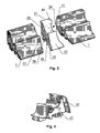
- ein Schaubild einer erfindungsgemäßen Verbindungsvorrichtung,
- Fig. 4
- ein Schaubild einer weiteren erfindungsgemäßen Verbindungsvorrichtung mit Führungsnasen und
- Fig. 5
- ein Schaubild eines mit einer erfindungsgemäßen Verbindungsvorrichtung verbundenen Dichtungsprofils.
- Mit 1 ist in
Fig. 1 ein Dichtungsprofil mit einem Fußteil 2 und einem Oberteil 3 bezeichnet. Am Fußteil 2 ist ein Verankerungskeder 4 angeordnet, der in eine Nut 21 eines Fenster- oder Türrahmens 22 eingeführt werden kann und sich dort verhakt. Der Verankerungskeder 4 ist dünnwandig ausgebildet und weist einen inneren Hohlraum 5 auf. An den Verankerungskeder 4 angrenzend ist zur Außenseite 6 des Dichtungsprofils 1 hin eine Dichtkante 7 angeschlossen. Diese Dichtkante 7 vermag sich auf dem Rahmenprofil 22 abzustützen und verhindert das Eindringen von Wasser. Zur Innenseite 8 des Dichtungsprofils 1 hin schließen weitere Dichtlippen 9 und 10 an, die einerseits den Wärmedurchgang zwischen Fensterinnenseite und Fensteraußenseite reduzieren und andererseits dem Dichtungsprofil 1 im eingebauten Zustand einen sicheren Stand verleihen. Das Oberteil 3 weist eine Anschlagdichtkante 11 und eine Zusatzdichtkante 12 auf, die zusammen den Wärmedurchgang vermindernd und damit Wärmeverluste reduzieren. Das Oberteil kann zur Reduzierung der Masse des Dichtprofils 1 einen Hohlraum 13 aufweisen. Dieser Hohlraum 13 sorgt durch die Reduzierung der Masse nicht nur für ein geringeres Gewicht des Dichtungsprofils 1, sondern vor allem für einen verringerten Wärmetransport und eine gute Biegbarkeit. - Das Fußteil 2 kann zumindest im Bereich des Verankerungskeders 4 ebenso wie der Verankerungskeder 4 aus kompaktem Werkstoff bestehen. Wie im in
Figur 1 dargestellten Ausführungsbeispiel kann aber auch die Dichtkante 7 noch aus kompaktem Werkstoff bestehen. Dieser Bereich des kompakten Werkstoffes ist mit 14 bezeichnet. Wenn die Dichtkante 7 ebenfalls aus dem kompakten Werkstoff gefertigt ist, ist diese vergleichsweise steif und legt sich damit auch ohne größere Anspresskräfte dicht an das Rahmenprofil 22 an. - Der restliche Querschnittsbereich des Dichtungsprofils 1, insbesondere aber das Oberteil 3 ist aus geschäumten Material gefertigt. Das geschäumte Material wird so hergestellt, daß die gebildete Oberfläche glatt und geschlossenporig ausgebildet ist. Nur im Inneren des Profils tritt eine Schäumung auf. Die Schäumung kann über die Dicke des Dichtungsprofils 1 unterschiedlich ausgebildet werden. Im Inneren des Dichtungsprofils 1 können größere Poren vorgesehen werden als zu den Oberflächen hin. Durch diese Dichteverteilung wird eine nochmals bessere Isolationswirkung bei gleichzeitig hoher mechanischer Stabilität der Oberflächen erzielt. Die Biegbarkeit des Profils 1 wird dadurch auch verbessert.
- Das geschäumte Material kann eine Dichte zwischen 0,35 und 0,60 g/cm3, vorzugsweise zwischen 0,40 und 0,55 g/cm3 aufweisen. Bei diesen geringen Dichten wurden sehr gute Isolationswerte erreicht.
- Um eine gute Festigkeit und Verankerbarkeit des Fußteils zu erzielen ist es besonders vorteilhaft, wenn das kompakte Material eine Shore Härte zwischen 60 und 80° Shore A aufweist.
- Durch eine derartige Ausgestaltung wird das Dichtungsprofil 1 so flexibel, daß dieses einfach um Ecken des Rahmenprofils 22 herumgeführt werden kann, ohne daß weitere, aufwendige Maßnahmen ergriffen werden müssen. Es ist damit nicht mehr notwendig, Formeckstücke einzusetzen oder das Dichtungsprofil im Knickbereich mit einem Unterlegteil zur Stabilisierung des Dichtungsprofil zu versehen, oder, wie es auch öfters praktiziert wird, mit einem Dichtungsmittel zu hinterspritzen. Das Rahmenprofil 22 kann als Blendrahmen ausgebildet sein.
- Vielmehr genügt es beim erfindungsgemäßen Dichtungsprofil 1, dieses an einer einzigen Stelle zusammenzufügen, wodurch Wärmeverluste weiter minimiert werden. Es kann beim Verbinden von Dichtungsprofilen 1 nicht immer sichergestellt werden, daß die Verbindung optimal ausgestaltet ist. Bei Verbindungen, die nur auf Stoß ausgebildet sind, ist oftmals die Pressung der Profilenden gegeneinander zu gering, so daß unter ungünstigen Bedingungen Spalten entstehen können. Daher wurden in der Vergangenheit diese Stoßstellen verklebt oder auch im Vorfeld vulkanisiert. Das Zusammenvulkanisieren ist jedoch nicht direkt beim Fensterbauer möglich, so daß der Aufwand gerade bei vielen verschiedenen Fenster- bzw. Türgrößen enorm ist.
- Das erfindungsgemäße Dichtungsprofil 1 kann ebenfalls an seinen Enden miteinander verklebt oder vulkanisiert werden.
- Dazu ist das Dichtungsprofil vorzugsweise aus EPDM hergestellt. Die beiden Querschnittsbereiche unterschiedlicher Dichte werden entweder durch vergleichsweise aufwendiges nachträgliches Zusammenfügen zweier Profilteile oder aber durch Koextrusion erzeugt.
- Das erfindungsgemäße Dichtungsprofil 1 weist aufgrund seiner beiden unterschiedlichen Dichten innere Spannungen auf. Durch diese inneren Spannungen ist es nicht möglich, gerade Schnittkanten bzw. Schnittflächen zu erzeugen. Auch wenn mit höchster Präzision geschnitten wird, wird die sich ergebende Schnittfläche immer eine Wölbung aufweisen.
- Trotzdem lassen sich diese Schnittflächen miteinander verkleben.
- Es wäre aber auch denkbar, daß die Schnittflächen nachträglich abgeschliffen oder abgefräst werden, um eine ebene Fläche und eine gerade Kante zu erzeugen, die sich durch einfaches Aneinanderfügen miteinander dicht verbinden lässt. Durch eine etwas größere Länge des Dichtungsprofils 1, als eigentlich für den jeweiligen Rahmen benötigt wird, kann eine dichte Verbindung geschaffen werden, bei der die Enden des Dichtungsprofils 1 gegeneinander gepresst werden.
- Allerdings ist das nachträgliche Abschleifen oder Abfräsen in den allermeisten Fällen wenig praktikabel.
- Es wurde daher noch nach einer Lösung gesucht, eine dichte Verbindung der Stoßstellen des Dichtungsprofils 1 zu schaffen.
- Diese Lösung wurde erfindungsgemäß darin gefunden, daß eine Verbindungsvorrichtung 31 vorgeschlagen wird, die einen Mittelabschnitt 32 aufweist, der im wesentlichen dieselbe Kontur aufweist, wie das Dichtungsprofil 1. Die dem Dichtunsprofil 1 zugewandten Seitenflächen 33 und 34 können so gewölbt sein, daß sich die Enden des Dichtungsprofils 1 vollflächig anzulegen vermögen. Der Mittelabschnitt 32 weist eine gewisse Dicke auf. Sobald die Verbindungsvorrichtung 31 zwischen zwei Enden eines Dichtungsprofils 1 gelegt wird, wird auch ein Anpressdruck der Schnittflächen des Dichtungsprofils 1 gegen die Seitenflächen 33 und 34 des Mittelabschnitts 32 erzeugt. Eine dichte Verbindung ist geschaffen.
- Um die Verbindungsvorrichtung 31 gut positionieren zu können, weist diese in ihrem Fußbereich 35 wie auch das Dichtungsprofil 1 einen Verankerungskeder 36 auf. Dichtkanten 37 und Dichtnasen 38, 39, 40 und 41, die denjenigen des Dichtungsprofils 1 entsprechen sind ebenfalls vorgesehen.
- Um gerade bei größeren Dicken des Mittelabschnitts 32, die für größere Anpressdrücke der Schnittflächen des Dichtungsprofils 1 sorgt, ein Ausweichen des Dichtungsprofils 1 zu vermeiden, ist es denkbar, daß am Mittelabschnitt 31 über die Seitenflächen 33 und 34 hinausragende Führungsnasen 42 vorgesehen werden, hinter die die Dichtungsprofile 1 einzugreifen vermögen. Die Führungsnasen können dabei punktuell oder auch flächig ausgebildet sein. Die Führungsnasen 42 sind im dargestellten Beispiel nicht nur an der Oberkante der Verbindungsvorrichtung 31 vorgesehen, sondern auch in deren Außenbereich.
- Gerade im Außenbereich besteht die Gefahr, daß ankommendes Wasser in den Stoßbereich eindringt. Im schlimmsten Fall wäre es sogar denkbar, daß dieses Wasser in das Innere eines Gebäudes eindringt.
- Wird nun eine Führungsnase 42 im Außenbereich vorgesehen, die die Stoßstelle in diesem Bereich überdeckt, so wird eine wirksamer Schutz vor Eindringen von Wasser geschaffen. Auch wird eine Zusätzliche Abdichtung der Stoßstelle gegen Zugluft geschaffen.
- Es ist denkbar, daß die Verbindungsvorrichtung 31 auch nicht dargestellte Kanäle aufweist, durch die hindurch Klebstoff eingespritzt werden kann, der zu den Seitenflächen 33 und 34 geleitet wird und so eine nachrägliche Verklebung zwischen der Verbindungsvorrichtung 31 und den Dichtungsprofilen 1 geschaffen werden kann.
- Die Verbindungsvorrichtung 31 kann, wie in den Zeichnungen dargestellt, als Geradeverbinder ausgebildet sein. Es ist aber auch denkbar, daß die Verbindungsvorrichtung 31 als Eckverbinder ausgebildet ist.
- Die Verbindungsvorrichtung 31 ist vorzugsweise wie das Dichtungsprofil 1 aus EPDM hergestellt und kann ebenfalls kompakte und geschäumte Bereiche aufweisen.
- Bei der Ausbildung der Seitenflächen 33 und 34 der Verbindungsvorrichtung 31 wurden sehr gute Ergebnisse erzielt, wenn diese einen negativen Radius von etwa 350 Millimeter aufweisen.
Claims (15)
- Dichtungsprofil mit einem Fußteil und einem konturierten Oberteil mit wenigstens einer Dichtkante, dadurch gekennzeichnet, daß das Dichtungsprofil aus wenigstens zwei Querschnittsbereichen besteht, wobei ein Bereich aus einem kompakten Material und ein anderer Bereich aus einem geschäumten Material besteht, wobei das Fußteil eine Rasteinrichtung aufweisen kann, mit dem es in einem Profil für Fenster- und/oder Türkonstruktionen verankerbar ist und wobei wenigstens ein Teil des Fußteils aus dem kompakten Material bestehen kann und daß das konturierte Oberteil aus dem geschäumten Material gefertigt sein kann, und daß das geschäumte Material an seinen Außenseiten eine glatte und geschlossenporige Oberfläche aufweisen kann.
- Dichtungsprofil nach Anspruch 1, dadurch gekennzeichnet, daß das geschäumte Material in seinem Inneren eine geringere Dichte aufweist als an seinen Oberflächen und/oder daß das geschäumte Material eine Dichte zwischen 0,35 und 0,60 g/cm3, vorzugsweise zwischen 0,40 und 0,55 g/cm3 aufweist und/oder daß das kompakte Material eine Shore-Härte zwischen 60 und 80° Shore A aufweist.
- Dichtungsprofil nach einem der vorangehenden Ansprüchen, dadurch gekennzeichnet, daß das Dichtungsprofil im Koextrusionsverfahren hergestellt ist und/oder daß das kompakte und das geschäumte Material aus demselben Rohstoff bestehen und vorzugsweise aus EPDM gefertigt sind und/oder daß das Dichtungsprofil wenigstens in einer Ebene eine gute Biegbarkeit aufweist.
- Vorrichtung zum Verbinden von zwei Enden von Dichtungsprofilen, insbesondere von Dichtungsprofilen für Fenster- und Türkonstruktionen zwischen Flügel und Blendrahmen, mit einem Fußteil und einem konturierten Oberteil gemäß einem der vorangehenden Ansprüche, das eine Oberkante, eine Vorderkante und eine Hinterkante aufweist, dadurch gekennzeichnet, daß die Vorrichtung als Einsetzteil ausgebildet ist, das zwischen die beiden Enden des Dichtungsprofils eingelegt wird.
- Vorrichtung nach Anspruch 4, dadurch gekennzeichnet, daß das Einsetzteil einen an die Kontur des Dichtungsprofils angepassten Mittelabschnitt aufweist.
- Vorrichtung nach Anspruch 4 oder 5, dadurch gekennzeichnet, daß das Einsetzteil wenigstens einen Führungsansatz aufweist.
- Vorrichtung nach Anspruch 6, dadurch gekennzeichnet, daß ein Führungsansatz wenigstens einen Teil des Oberteils im Stoßbereich überdeckt.
- Vorrichtung nach Anspruch 6 oder 7, dadurch gekennzeichnet, daß ein Führungsansatz an der Hinterkante, an der Oberkante und/oder an der Vorderkante des Dichtungsprofils vorgesehen ist.
- Vorrichtung nach einem der Ansprüche 4 bis 8, dadurch gekennzeichnet, daß der Mittelabschnitt an seinen den Enden des Dichtungsprofils zugewandten Seiten eine Wölbung aufweist.
- Vorrichtung nach einem der Ansprüche 4 bis 9, dadurch gekennzeichnet, daß die Vorrichtung als Gerade- und/oder Eckverbinder ausgebildet ist.
- Fenster- oder Türdichtung mit einem Dichtungsprofil nach einem der Ansprüche 1 bis 3, dadurch gekennzeichnet, daß das Dichtungsprofil in einen Blendrahmen eingelegt und um die Ecken des Blendrahmens herumgeführt ist.
- Fenster- oder Türdichtung nach Anspruch 11, dadurch gekennzeichnet, daß die Endflächen des Dichtungsprofils miteinander verklebt sind.
- Fenster- oder Türdichtung mit einem Dichtungsprofil nach einem der Ansprüche 1 bis 3, dadurch gekennzeichnet, daß die Endflächen des Dichtungsprofils mit einer Verbindungsvorrichtung nach einem der Ansprüche 4 bis 10 miteinander dicht verbunden werden
- Fenster- oder Türdichtung nach Anspruch 13, dadurch gekennzeichnet, daß eine zusätzliche Verklebung zwischen Dichtungsprofil und Verbindungsvorrichtung vorgesehen ist.
- Fenster- oder Türdichtung nach Anspruch 13 oder 14, dadurch gekennzeichnet, daß die Dichtung entweder um die Ecken eines Blendrahmens herumgeführt oder mit Eckverbindern ausgerüstet ist.
Applications Claiming Priority (1)
| Application Number | Priority Date | Filing Date | Title |
|---|---|---|---|
| DE102008061709A DE102008061709A1 (de) | 2008-12-12 | 2008-12-12 | Dichtungsprofil, Verbindungsvorrichtung und Dichtung |
Publications (2)
| Publication Number | Publication Date |
|---|---|
| EP2196614A2 true EP2196614A2 (de) | 2010-06-16 |
| EP2196614A3 EP2196614A3 (de) | 2014-06-04 |
Family
ID=42102163
Family Applications (1)
| Application Number | Title | Priority Date | Filing Date |
|---|---|---|---|
| EP09178992.5A Withdrawn EP2196614A3 (de) | 2008-12-12 | 2009-12-11 | Dichtungsprofil, Verbindungsvorrichtung und Dichtung |
Country Status (2)
| Country | Link |
|---|---|
| EP (1) | EP2196614A3 (de) |
| DE (1) | DE102008061709A1 (de) |
Cited By (3)
| Publication number | Priority date | Publication date | Assignee | Title |
|---|---|---|---|---|
| EP2754842A1 (de) | 2013-01-11 | 2014-07-16 | SCHÜCO International KG | Dichtungsprofil für ein Rahmenprofil und Rahmenprofil |
| CN110130784A (zh) * | 2019-06-21 | 2019-08-16 | 上海鸿业幕墙装饰工程有限公司 | 一种系统门窗隔热密封构件 |
| EP4001576A3 (de) * | 2020-11-20 | 2022-06-29 | GUTMANN Bausysteme GmbH | Rahmen-mitteldichtung sowie fassadenkonstruktion |
Families Citing this family (5)
| Publication number | Priority date | Publication date | Assignee | Title |
|---|---|---|---|---|
| EP2397643B1 (de) * | 2010-06-18 | 2018-03-14 | Kawneer Aluminium Deutschland Inc. | Verbindungselement zum Schließen eines Dichtungsstoßes an Fassaden |
| AT513521B1 (de) * | 2012-11-09 | 2017-01-15 | Drutex S A | Kunststofffenster |
| DE102014217713B4 (de) | 2014-09-04 | 2022-11-03 | Roto Frank Ag | Dichtungsstrang für eine Beschlagteilanordnung |
| DE102015116062A1 (de) * | 2015-09-23 | 2017-03-23 | Hueck Gmbh & Co. Kg | Türanordnung sowie Bauwerkanordnung |
| DE102021111784A1 (de) | 2021-05-06 | 2022-11-10 | SCHÜCO International KG | Dichtungsprofil sowie Blendrahmen und Flügelrahmen |
Citations (1)
| Publication number | Priority date | Publication date | Assignee | Title |
|---|---|---|---|---|
| JPH07314560A (ja) * | 1994-05-23 | 1995-12-05 | Nishikawa Rubber Co Ltd | ウエザーストリップの接合方法及びその装置 |
Family Cites Families (9)
| Publication number | Priority date | Publication date | Assignee | Title |
|---|---|---|---|---|
| GB1460169A (en) * | 1974-03-13 | 1976-12-31 | Schlegel Uk Ltd | Moulded corners or joints of door seals and the like |
| DE7517233U (de) * | 1975-05-30 | 1976-01-02 | Duepree, Hans-Werner, 4830 Guetersloh | Eckverbinder fuer wandanschlussleisten von kuechenmoebeln |
| US5538578A (en) * | 1992-10-30 | 1996-07-23 | Kinugawa Rubber Ind. Co., Ltd. | Method for joining end portions of weatherstrip and apparatus for forming joining member therefor |
| DE4326115A1 (de) * | 1993-08-04 | 1995-02-09 | Hubert Funk | Profildichtung für Fenster und sowie Verfahren und Vorrichtung zu ihrer Anbringung |
| DE29615572U1 (de) * | 1996-09-06 | 1998-01-08 | Semperit Ag Holding, Wien | Strangförmige Dichtung für Fenster o.dgl. Bauteile |
| DE19719474A1 (de) * | 1997-05-07 | 1998-10-08 | Bruegmann Frisoplast Gmbh | Strangdichtung |
| DE29720053U1 (de) * | 1997-11-12 | 1999-03-18 | Meteor Gummiwerke K. H. Bädje GmbH & Co, 31167 Bockenem | Dichtungsverbindungselement, Dichtungsendstück und Dichtung |
| DE102004024127B3 (de) * | 2004-05-14 | 2005-08-25 | Deventer Profile Gmbh & Co Kg | Elastische Strangdichtung für Fenster, Türen oder dgl. |
| DE202008012065U1 (de) * | 2008-09-11 | 2008-11-27 | Deventer Profile Gmbh & Co Kg | Elastische Strangdichtung für Fenster, Türen o.dgl. |
-
2008
- 2008-12-12 DE DE102008061709A patent/DE102008061709A1/de not_active Withdrawn
-
2009
- 2009-12-11 EP EP09178992.5A patent/EP2196614A3/de not_active Withdrawn
Patent Citations (1)
| Publication number | Priority date | Publication date | Assignee | Title |
|---|---|---|---|---|
| JPH07314560A (ja) * | 1994-05-23 | 1995-12-05 | Nishikawa Rubber Co Ltd | ウエザーストリップの接合方法及びその装置 |
Cited By (5)
| Publication number | Priority date | Publication date | Assignee | Title |
|---|---|---|---|---|
| EP2754842A1 (de) | 2013-01-11 | 2014-07-16 | SCHÜCO International KG | Dichtungsprofil für ein Rahmenprofil und Rahmenprofil |
| DE102013100242A1 (de) | 2013-01-11 | 2014-07-17 | SCHÜCO International KG | Dichtungsprofil für ein Rahmenprofil und Rahmenprofil |
| DE202013012777U1 (de) | 2013-01-11 | 2019-06-17 | SCHÜCO International KG | Dichtungsprofil für ein Rahmenprofil und Rahmenprofil |
| CN110130784A (zh) * | 2019-06-21 | 2019-08-16 | 上海鸿业幕墙装饰工程有限公司 | 一种系统门窗隔热密封构件 |
| EP4001576A3 (de) * | 2020-11-20 | 2022-06-29 | GUTMANN Bausysteme GmbH | Rahmen-mitteldichtung sowie fassadenkonstruktion |
Also Published As
| Publication number | Publication date |
|---|---|
| EP2196614A3 (de) | 2014-06-04 |
| DE102008061709A1 (de) | 2010-06-17 |
Similar Documents
| Publication | Publication Date | Title |
|---|---|---|
| EP2196614A2 (de) | Dichtungsprofil, Verbindungsvorrichtung und Dichtung | |
| EP2492428B3 (de) | Anputzleiste sowie Bauwerksecke mit Anputzleiste | |
| DE102016117957A1 (de) | Dichtungsanordnung für ein Kraftfahrzeugfenster, Dichtungsverbund und Verfahren zum Herstellen eines Dichtungsverbundes | |
| EP2907959B1 (de) | Eckverbinder und verfahren zu ihrer herstellung | |
| EP2363567B1 (de) | Rahmen eines Kunststofffensters oder einer Kunststofftür | |
| DE69734632T2 (de) | Wärmedämmender Trennprofilkörper zum Einsetzen zwischen Aluminiumprofilen zur Verwendung bei der Herstellung von Türen und Fenster | |
| EP1659254B1 (de) | Flügel für ein Fenster oder eine Tür | |
| DE69808045T2 (de) | Verfahren und Vorrichtung zum thermischen Verbinden von Elementen zum Formen eines Rahmens | |
| EP2055462A2 (de) | Verfahren zum Verschweißen von auf Gehrung geschnittenen Rahmenprofilen für Fenster, Türen oder dergleichen sowie Dichtungsstreifen zur Verwendung bei solchen Rahmenprofilen | |
| EP1568843A2 (de) | Schiebeelement-Dichtung | |
| DE202005021480U1 (de) | Verbindungselemente für Platten, insbesondere aus Glas, zur Befestigung derselben und derart ausgerüstete Platten | |
| DE29507847U1 (de) | Dichtungsleiste für Blendrahmen und Flügelrahmen von Fenstern bzw. Türen | |
| EP4086420A1 (de) | Dichtungsprofil sowie blendrahmen und flügelrahmen | |
| EP0746658B1 (de) | Dichtungsanordnung für Fassaden | |
| EP2469003B1 (de) | Blendrahmen | |
| DE202005009450U1 (de) | Fenster- oder Türelement mit Klebeverbindung zwischen Rahmen und Scheibe und Dichtungsleiste | |
| EP4191012B1 (de) | Gebäudeöffnungs-schliesselement und verfahren zu seiner herstellung | |
| AT393534B (de) | Dichtungs-formstueck | |
| DE102020000162B3 (de) | Nutleiste und Verfahren zur Herstellung | |
| EP1201871A2 (de) | Verbindungselement für aufeinandertreffende Hohlprofilabschnitte | |
| EP3502403B1 (de) | Fenster- oder türprofil | |
| EP1989386B1 (de) | Rahmenbaugruppe | |
| EP2284349B1 (de) | Rahmenbaugruppe für ein Fenster oder eine Tür | |
| EP1980702B1 (de) | Rahmenkonstruktion für Fenster und/oder Türen | |
| DE9216903U1 (de) | Abdichtungsvorrichtung für Fensterrahmen |
Legal Events
| Date | Code | Title | Description |
|---|---|---|---|
| PUAI | Public reference made under article 153(3) epc to a published international application that has entered the european phase |
Free format text: ORIGINAL CODE: 0009012 |
|
| AK | Designated contracting states |
Kind code of ref document: A2 Designated state(s): AT BE BG CH CY CZ DE DK EE ES FI FR GB GR HR HU IE IS IT LI LT LU LV MC MK MT NL NO PL PT RO SE SI SK SM TR |
|
| RIC1 | Information provided on ipc code assigned before grant |
Ipc: E06B 7/23 20060101ALI20140219BHEP Ipc: E06B 7/22 20060101AFI20140219BHEP |
|
| PUAL | Search report despatched |
Free format text: ORIGINAL CODE: 0009013 |
|
| AK | Designated contracting states |
Kind code of ref document: A3 Designated state(s): AT BE BG CH CY CZ DE DK EE ES FI FR GB GR HR HU IE IS IT LI LT LU LV MC MK MT NL NO PL PT RO SE SI SK SM TR |
|
| RIC1 | Information provided on ipc code assigned before grant |
Ipc: B29C 65/50 20060101ALI20140430BHEP Ipc: E06B 7/23 20060101ALI20140430BHEP Ipc: B29C 65/00 20060101ALI20140430BHEP Ipc: E06B 7/22 20060101AFI20140430BHEP |
|
| 17P | Request for examination filed |
Effective date: 20140901 |
|
| RBV | Designated contracting states (corrected) |
Designated state(s): AT BE BG CH CY CZ DE DK EE ES FI FR GB GR HR HU IE IS IT LI LT LU LV MC MK MT NL NO PL PT RO SE SI SK SM TR |
|
| RAP1 | Party data changed (applicant data changed or rights of an application transferred) |
Owner name: SAPA AS |
|
| STAA | Information on the status of an ep patent application or granted ep patent |
Free format text: STATUS: EXAMINATION IS IN PROGRESS |
|
| 17Q | First examination report despatched |
Effective date: 20170413 |
|
| STAA | Information on the status of an ep patent application or granted ep patent |
Free format text: STATUS: THE APPLICATION IS DEEMED TO BE WITHDRAWN |
|
| 18D | Application deemed to be withdrawn |
Effective date: 20240702 |