EP2196428B1 - Teleskopausleger - Google Patents
Teleskopausleger Download PDFInfo
- Publication number
- EP2196428B1 EP2196428B1 EP20090075524 EP09075524A EP2196428B1 EP 2196428 B1 EP2196428 B1 EP 2196428B1 EP 20090075524 EP20090075524 EP 20090075524 EP 09075524 A EP09075524 A EP 09075524A EP 2196428 B1 EP2196428 B1 EP 2196428B1
- Authority
- EP
- European Patent Office
- Prior art keywords
- box section
- inner box
- head
- locking
- box
- Prior art date
- Legal status (The legal status is an assumption and is not a legal conclusion. Google has not performed a legal analysis and makes no representation as to the accuracy of the status listed.)
- Active
Links
- 239000004606 Fillers/Extenders Substances 0.000 title 1
- 230000008878 coupling Effects 0.000 claims description 4
- 238000010168 coupling process Methods 0.000 claims description 4
- 238000005859 coupling reaction Methods 0.000 claims description 4
- 238000006073 displacement reaction Methods 0.000 claims 1
- 238000000034 method Methods 0.000 description 2
- 238000003780 insertion Methods 0.000 description 1
- 230000037431 insertion Effects 0.000 description 1
Images


Classifications
-
- B—PERFORMING OPERATIONS; TRANSPORTING
- B66—HOISTING; LIFTING; HAULING
- B66C—CRANES; LOAD-ENGAGING ELEMENTS OR DEVICES FOR CRANES, CAPSTANS, WINCHES, OR TACKLES
- B66C23/00—Cranes comprising essentially a beam, boom, or triangular structure acting as a cantilever and mounted for translatory of swinging movements in vertical or horizontal planes or a combination of such movements, e.g. jib-cranes, derricks, tower cranes
- B66C23/62—Constructional features or details
- B66C23/64—Jibs
- B66C23/70—Jibs constructed of sections adapted to be assembled to form jibs or various lengths
- B66C23/701—Jibs constructed of sections adapted to be assembled to form jibs or various lengths telescopic
- B66C23/708—Jibs constructed of sections adapted to be assembled to form jibs or various lengths telescopic locking devices for telescopic jibs
-
- B—PERFORMING OPERATIONS; TRANSPORTING
- B66—HOISTING; LIFTING; HAULING
- B66C—CRANES; LOAD-ENGAGING ELEMENTS OR DEVICES FOR CRANES, CAPSTANS, WINCHES, OR TACKLES
- B66C23/00—Cranes comprising essentially a beam, boom, or triangular structure acting as a cantilever and mounted for translatory of swinging movements in vertical or horizontal planes or a combination of such movements, e.g. jib-cranes, derricks, tower cranes
- B66C23/62—Constructional features or details
- B66C23/64—Jibs
- B66C23/70—Jibs constructed of sections adapted to be assembled to form jibs or various lengths
- B66C23/701—Jibs constructed of sections adapted to be assembled to form jibs or various lengths telescopic
Definitions
- the invention relates to a telescopic boom, in particular telescopic boom for mobile crane, with a base box in which one or more inner boxes are guided substantially coaxially in each other, which are successively by a trained as a hydraulic cylinder / piston system telescoping selectively on - and extendable, wherein the hydraulic cylinder / piston system is fixed at one of its two ends in the base box and with its extendable part by means of a locking and locking unit (SVE) can be coupled to the respectively to be moved inner box and the respective inner box in at least one retracted and in its extended Position can be locked mechanically in each case by a bolting device which can be actuated by the securing and locking units (SVE) in relation to the next larger inner box or the basic box and can be unlocked immediately before the method for carrying out the coupling; and wherein at the first innermost inner box at the outside end of a head with or without pulleys is provided.
- a locking and locking unit SVE
- the object of the invention is to introduce, in particular bringing together the new To facilitate box with the receiving inner box.
- the head is designed such that all parts belonging to the head outside the free cross-section of this inner box are arranged so that a further boom box in this inner box can be inserted for an extension of the boom that on the inside of the head itself diametrically opposite each a forwardly open Verbolzungsgabel is arranged, in which the locking bolts of the new inner box to be inserted to its centering are inserted and that the securing and locking unit for coupling this inner box to the position of the locking bolt is advancing or retractable.
- the bilaterally arranged on the head, forwardly open Verbolzungsgabeln allow easy insertion of the new inner box to be inserted with its also on both sides, congruent with the Verbolzungsgabeln arranged locking bolt.
- the telescoping system moves so far in the box to be inserted, that with the extendable cylinder Verbolzungs coupled (SVE) connects the box (secures) and then mechanically unlock the locking bolt. Then we put the box to be inserted with the telescoping unit in the existing boom part and can be locked at any locking point again. This process is carried out automatically by means of an existing controller. Dismantling takes place in reverse order.
- the receiving box of a telescopic boom which may be an inner box or the base box, is indicated in the figures with 1.
- This box is at its front end with one Head 8, which carries the pulleys 9, equipped, this head is arranged with all its functional parts so that it surrounds the outer periphery of the box 1, so that the front clear cross-sectional area remains free.
- a new inner box 2 can be inserted into this female box 1 to extend the boom.
- This inner box is provided with the usual locking bolt 4 at its rear end.
- the locking pin 4 are inserted, so that so that the two boxes are positioned to each other.
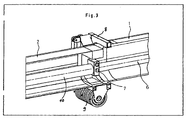
- FIG. 3 shows the arranged inside the boxes telescopic system 6,10 with the securing and locking device 7, which is located on the extendable cylinder 10.
- the telescoping system moves so far in the box 2 to be inserted, that with the extendable cylinder 10 Verbolzungs worn (SVE) 7 couples the box (secures) and then mechanically lock the locking pin 4 can unlock. Thereafter, we inserted the box 2 with the telescoping unit in the existing boom part 1 and can be locked at any locking point again.
- SVE Verbolzungs worn
Landscapes
- Engineering & Computer Science (AREA)
- Mechanical Engineering (AREA)
- Jib Cranes (AREA)
Description
- Die Erfindung betrifft einen Teleskopausleger, insbesondere Teleskopausleger für Mobilkran, mit einem Grundkasten, in dem ein oder mehrere Innenkästen im wesentlichen koaxial in einander geführt sind, die nacheinander durch ein als hydraulisches Zylinder/Kolben-System ausgebildetes Teleskopiersystem wahlweise ein - und ausfahrbar sind, wobei das hydraulische Zylinder/Kolben-System an einem seiner beiden Enden im Grundkasten fixiert ist und mit seinem ausfahrbarem Teil mittels einer Sicherungs- und Verriegelungseinheit (SVE) an den jeweils zu verfahrenden Innenkasten ankoppelbar ist und der jeweilige Innenkasten in mindestens einer eingefahrenen und in seiner ausgefahrenen Stellung jeweils durch eine von den Sicherungs- und Verriegelungseinheiten (SVE) betätigbare Verbolzungseinrichtung gegenüber dem nächstgrößeren Innenkasten oder dem Grundkasten mechanisch verriegelbar und unmittelbar vor dem Verfahren zur Durchführung des Ankoppelns entriegelbar ist,
und wobei am zunächst innersten Innenkasten am außenseitigen Ende ein Kopf mit oder ohne Umlenkrollen vorgesehen ist. - Aus der
DE 101 42 847 C1 ist ein Teleskopausleger mit einer derartig ausgebildeten Sicherungs- und Verriegelungseinheit- kurz SVE genannt - bekannt. - Weiterhin ist es aus der
DE 10 2006 023 371 A1 bekannt den Kranausleger verlängerbar auszugestalten, wozu der die Umlenkrolle aufnehmende Kopf so gestaltet ist, dass alle für die Funktion des Kopfes notwendigen Teile am Außenumfang des bis dahin innersten Kastens angeordnet sind, so dass der vordere Querschnitt dieses innersten Kastens so frei ist, dass ein der weiteren Verlängerung dienender Kasten in diesen bisher innersten Kasten einschiebbar ist. - Aufgabe der Erfindung ist es, das Einführen, insbesondere Zusammenbringen des neuen Kastens mit dem aufnehmenden Innenkasten zu erleichtern.
- Gelöst wird diese Aufgabe erfindungsgemäß dadurch dass der Kopf derart ausgebildet ist, dass alle zum Kopf gehörenden Teile außerhalb des freien Querschnittes dieses Innenkastens angeordnet sind, so dass für eine Verlängerung des Auslegers ein weiterer Auslegerkasten in diesen Innenkasten einschiebbar ist dass an der Innenseite des Kopfes sich diametral gegenüberliegend je eine nach vorne offene Verbolzungsgabel angeordnet ist, in die die Verriegelungsbolzen des einzuschiebenden neuen Innenkastens zu dessen Zentrierung einführbar sind und dass die Sicherungs- und Verriegelungseinheit zum Ankoppeln dieses Innenkastens bis zur Position des Verriegelungsbolzens vorfahr- bzw. ausfahrbar ist.
- Die beidseitig am Kopf angeordneten, nach vorn offenen Verbolzungsgabeln ermöglichen ein einfaches Einfädeln des einzuschiebenden neuen Innenkastens mit seinem ebenfalls beidseitig, kongruent zu den Verbolzungsgabeln angeordneten Verriegelungsbolzen.
Das Teleskopiersystem fährt soweit in den einzuschiebenden Kasten, dass die mit der am ausfahrbaren Zylinder befindlichen Verbolzungseinrichtung (SVE) den Kasten ankoppelt (sichert) und anschließend mechanisch die Verriegelungsbolzen entriegeln kann.
Danach wir der einzuschiebende Kasten mit der Teleskopiereinheit in das vorhandene Auslegerteil hineingezogen und kann an jeder beliebigen Verriegelungsstelle wieder verriegelt werden. Dieser Vorgang erfolgt automatisch mittels vorhandener Steuerung.
Die Demontage erfolgt in umgekehrter Reihenfolge. - Die Erfindung soll nachfolgend mit Bezug auf die Zeichnungen erläutert werden. Dabei zeigt:
-
Fig.1 eine perspektivische Ansicht des Kopfes eines aufnehmenden Kastens eines Teleskopauslegers und einen in diesen einzuführenden neuen Kasten, -
Fig.2 das Einführen und -
Fig.3 den eingeführten und den aufnehmenden Kasten jeweils aufgeschnitten mit dem darin angeordneten Teleskopiersystem und der Sicherungs- und Verriegelungseinrichtung SVE. - Der aufnehmende Kasten eines Teleskopauslegers, der ein Innenkasten oder auch der Grundkasten sein kann, ist in den Figuren mit 1 bezeichnet.
- Gemäß der
DE 10 2006 023 371 A1 ist dieser Kasten an seinem vorderen Ende mit einem Kopf 8, der die Umlenkrollen 9 trägt, ausgerüstet, wobei dieser Kopf mit allen seinen Funktionsteilen so angeordnet ist, dass er den Außenumfang des Kastens 1 umgibt, so dass dessen vordere lichte Querschnittsfläche frei bleibt.
Damit kann zur Verlängerung des Auslegers ein neuer Innenkasten 2 in diesen aufnehmenden Kasten 1 eingeschoben werden. - Dieser Innenkasten ist mit dem üblichen Verriegelungsbolzen 4 an seinem hinteren Ende versehen.
- Um nun das Zusammenbringen der beiden Kästen 1 und 2 zu erleichtern, sind am Kopf 8, und zwar an dessen Innenseite, sich diametral gegenüberliegend nach vorne offen Verbolzungsgabeln 3 angebracht.
- In diese werden die Verriegelungsbolzen 4 eingeführt, so dass damit die beiden Kästen zueinander positioniert werden.
- Dies ist in der
Figur 2 dargestellt. - Die
Figur 3 zeigt die im Inneren der Kästen angeordnete Teleskopiersystem 6,10 mit der Sicherungs- und Verriegelungseinrichtung 7, die sich am ausfahrbaren Zylinder 10 befindet. - Das Teleskopiersystem fährt soweit in den einzuschiebenden Kasten 2, dass die mit der am ausfahrbaren Zylinder 10 befindlichen Verbolzungseinrichtung (SVE) 7 den Kasten ankoppelt (sichert) und anschließend mechanisch die Verriegelungsbolzen 4 entriegeln kann.
Danach wir der einzuschiebende Kasten 2 mit der Teleskopiereinheit in das vorhandene Auslegerteil 1 hineingezogen und kann an jeder beliebigen Verriegelungsstelle wieder verriegelt werden.
Claims (1)
- Teleskopausleger, insbesondere Teleskopausleger für Mobilkran, mit einem Grundkasten (1), in dem ein oder mehrere Innenkästen im wesentlichen koaxial in einander geführt sind, die nacheinander durch ein als hydraulisches Zylinder/Kolben-System ausgebildetes Teleskopiersystem Sicherungs- und Verriegelungseinheit (7) (6,10) wahlweise ein - und ausfahrbar sind, wobei das hydraulische Zylinder/Kolben-System an einem seiner beiden Enden im Grundkasten fixiert ist und mit seinem ausfahrbarem Teil mittels eine an den jeweils zu verfahrenden Innnenkasten ankoppelbar ist und der jeweilige Innenkasten in mindestens einer eingefahrenen und in seiner ausgefahrenen Stellung jeweils durch eine von den Sicherungs- und Verriegelungseinheiten (7) betätigbare Verbolzungseinrichtung gegenüber dem nächstgrößeren Innenkasten oder dem Grundkasten mechanisch verriegelbar und unmittelbar vor dem Verfahren zur Durchführung des Ankoppelns entriegelbar ist,
und wobei am zunächst innersten Innenkasten am außenseitigen Ende ein Kopf (8) mit oder ohne Umlenkrollen vorgesehen ist dadurch gekennzeichnet, dass der Kopf derart ausgebildet ist, dass alle zum Kopf gehörenden Teile außerhalb des freien Querschnittes dieses Innenkastens angeordnet sind,
so dass für eine Verlängerung des Auslegers ein weiterer Auslegerkasten in diesen Innenkasten einschiebbar ist,
dass an der Innenseite des Kopfes (8) sich diametral gegenüberliegend je eine nach vorne offene Verbolzungsgabel (3) angeordnet ist, in die die Verriegelungsbolzen (4) des einzuschiebenden neuen Innenkastens (2) zu dessen Zentrierung einführbar sind und dass das Teleskopiersystem (6,10) mit der Sicherungs- und Verriegelungseinheit (7) zum Ankoppeln dieses Innenkastens bis zur Position des Verriegelungsbolzens (4) vorfahr- bzw. ausfahrbar ist.
Applications Claiming Priority (1)
| Application Number | Priority Date | Filing Date | Title |
|---|---|---|---|
| DE200820016604 DE202008016604U1 (de) | 2008-12-15 | 2008-12-15 | Teleskopausleger |
Publications (2)
| Publication Number | Publication Date |
|---|---|
| EP2196428A1 EP2196428A1 (de) | 2010-06-16 |
| EP2196428B1 true EP2196428B1 (de) | 2013-07-31 |
Family
ID=40459454
Family Applications (1)
| Application Number | Title | Priority Date | Filing Date |
|---|---|---|---|
| EP20090075524 Active EP2196428B1 (de) | 2008-12-15 | 2009-11-27 | Teleskopausleger |
Country Status (4)
| Country | Link |
|---|---|
| EP (1) | EP2196428B1 (de) |
| CN (1) | CN101746682B (de) |
| DE (1) | DE202008016604U1 (de) |
| ES (1) | ES2432523T3 (de) |
Families Citing this family (2)
| Publication number | Priority date | Publication date | Assignee | Title |
|---|---|---|---|---|
| DE102013011173B4 (de) * | 2013-07-04 | 2019-05-23 | Liebherr-Werk Ehingen Gmbh | Verfahren zur Montage eines Krans sowie Anlenkschuss, Teleskopausleger und Kran |
| JP2022084003A (ja) * | 2020-11-25 | 2022-06-06 | タダノ デマグ ゲーエムベーハー | 基本伸縮ジブおよび追加伸縮ジブを有する移動式クレーンの伸縮ジブシステム、および対応する方法 |
Family Cites Families (8)
| Publication number | Priority date | Publication date | Assignee | Title |
|---|---|---|---|---|
| US4492311A (en) * | 1981-08-17 | 1985-01-08 | Fmc Corporation | Coupling and latching mechanism for extensible boom |
| US4664272A (en) * | 1981-11-05 | 1987-05-12 | Kidde, Inc. | Telescoping crane boom with locking and indicator means |
| AT403040B (de) * | 1994-03-18 | 1997-10-27 | Zimmermann Horst | Teleskopierstab |
| DE19824672A1 (de) * | 1997-05-28 | 1998-12-03 | Mannesmann Ag | Kran mit einem Teleskopausleger |
| DE29824453U1 (de) * | 1997-05-28 | 2001-03-01 | Mannesmann AG, 40213 Düsseldorf | Kran mit einem Teleskopausleger |
| DE10142847C1 (de) | 2001-08-29 | 2002-11-21 | Demag Mobile Cranes Gmbh & Co | Teleskopausleger |
| DE102006023371A1 (de) | 2006-05-16 | 2007-11-22 | Terex-Demag Gmbh & Co. Kg | Teleskopierbarer Kranausleger |
| DE102007052954B3 (de) * | 2007-10-31 | 2009-07-09 | Terex Demag Gmbh | Kran mit Teleskopausleger |
-
2008
- 2008-12-15 DE DE200820016604 patent/DE202008016604U1/de not_active Expired - Lifetime
-
2009
- 2009-10-15 CN CN200910206354.0A patent/CN101746682B/zh active Active
- 2009-11-27 ES ES09075524T patent/ES2432523T3/es active Active
- 2009-11-27 EP EP20090075524 patent/EP2196428B1/de active Active
Also Published As
| Publication number | Publication date |
|---|---|
| CN101746682A (zh) | 2010-06-23 |
| CN101746682B (zh) | 2014-04-30 |
| DE202008016604U1 (de) | 2009-03-19 |
| EP2196428A1 (de) | 2010-06-16 |
| ES2432523T3 (es) | 2013-12-04 |
Similar Documents
| Publication | Publication Date | Title |
|---|---|---|
| DE19824671C2 (de) | Kran mit einem Teleskopausleger | |
| EP2465809B1 (de) | Teleskopiersystem für Kranausleger und Zusatzausleger | |
| EP1072554B1 (de) | Kran mit einem Teleskopausleger | |
| DE29824453U1 (de) | Kran mit einem Teleskopausleger | |
| DE10154730A1 (de) | Zwischen einer Schließpostion und einer Öffnungsposition verstellbares Hardtop-Fahrzeugverdeck | |
| DE202008007903U1 (de) | Verriegelungsvorrichtung mit Zylinderbetätigung zur Seite | |
| DE202005012049U1 (de) | Teleskopierbarer Schiebeholm | |
| EP2142464B1 (de) | Kran mit teleskopausleger | |
| EP2196428B1 (de) | Teleskopausleger | |
| DE19607683B4 (de) | Mobilkran mit einer lösbaren, den Unterwagen mit dem Oberwagen verbindenden Kupplung | |
| DE102013011173B4 (de) | Verfahren zur Montage eines Krans sowie Anlenkschuss, Teleskopausleger und Kran | |
| DE102012002122B4 (de) | Verriegelungsvorrichtung für einen Teleskopausleger | |
| DE102013011180B4 (de) | Kragenlagerung für einen Teleskopausleger sowie Teleskopausleger und Kran | |
| EP1388616A1 (de) | Vorrichtung zum Kuppeln und Entkuppeln der Anschlussenden von Druckmittelleitungen | |
| EP2592287B1 (de) | Teleskopwelle mit Zugelement | |
| DE10007773B4 (de) | Kran mit einem Teleskopausleger | |
| DE19926131B4 (de) | Teleskop-Ausleger | |
| DE19812472C2 (de) | Hebeeinrichtung zum Anheben schwerer Lasten, insbesondere entgleister Schienenfahrzeuge | |
| DE102008048356A1 (de) | Vorrichtung zum Verlegen einer vorgefertigten Auskleidung in U-Bahnstationen und Verkehrstunneln | |
| EP1293471B1 (de) | Teleskopausleger | |
| EP1055635B1 (de) | Kran mit Einem Teleskopausleger | |
| DE29824867U1 (de) | Kran mit einem Teleskopausleger | |
| DE102021130736B4 (de) | Teleskopauslegersystem eines Mobilkrans mit einem Grundteleskopausleger und einem Zusatzteleskopausleger und Verfahren hierzu | |
| DE102006023318A1 (de) | Kolben-Zylinder-Einheit | |
| DE10164600C2 (de) | Teleskopausleger |
Legal Events
| Date | Code | Title | Description |
|---|---|---|---|
| PUAI | Public reference made under article 153(3) epc to a published international application that has entered the european phase |
Free format text: ORIGINAL CODE: 0009012 |
|
| AK | Designated contracting states |
Kind code of ref document: A1 Designated state(s): AT BE BG CH CY CZ DE DK EE ES FI FR GB GR HR HU IE IS IT LI LT LU LV MC MK MT NL NO PL PT RO SE SI SK SM TR |
|
| AX | Request for extension of the european patent |
Extension state: AL BA RS |
|
| 17P | Request for examination filed |
Effective date: 20101105 |
|
| GRAP | Despatch of communication of intention to grant a patent |
Free format text: ORIGINAL CODE: EPIDOSNIGR1 |
|
| RAP1 | Party data changed (applicant data changed or rights of an application transferred) |
Owner name: TEREX CRANES GERMANY GMBH |
|
| GRAS | Grant fee paid |
Free format text: ORIGINAL CODE: EPIDOSNIGR3 |
|
| GRAP | Despatch of communication of intention to grant a patent |
Free format text: ORIGINAL CODE: EPIDOSNIGR1 |
|
| INTG | Intention to grant announced |
Effective date: 20130531 |
|
| GRAA | (expected) grant |
Free format text: ORIGINAL CODE: 0009210 |
|
| AK | Designated contracting states |
Kind code of ref document: B1 Designated state(s): AT BE BG CH CY CZ DE DK EE ES FI FR GB GR HR HU IE IS IT LI LT LU LV MC MK MT NL NO PL PT RO SE SI SK SM TR |
|
| REG | Reference to a national code |
Ref country code: GB Ref legal event code: FG4D Free format text: NOT ENGLISH Ref country code: CH Ref legal event code: EP |
|
| REG | Reference to a national code |
Ref country code: AT Ref legal event code: REF Ref document number: 624494 Country of ref document: AT Kind code of ref document: T Effective date: 20130815 |
|
| REG | Reference to a national code |
Ref country code: IE Ref legal event code: FG4D Free format text: LANGUAGE OF EP DOCUMENT: GERMAN |
|
| REG | Reference to a national code |
Ref country code: DE Ref legal event code: R096 Ref document number: 502009007661 Country of ref document: DE Effective date: 20130926 |
|
| REG | Reference to a national code |
Ref country code: NL Ref legal event code: T3 |
|
| REG | Reference to a national code |
Ref country code: ES Ref legal event code: FG2A Ref document number: 2432523 Country of ref document: ES Kind code of ref document: T3 Effective date: 20131204 |
|
| REG | Reference to a national code |
Ref country code: LT Ref legal event code: MG4D |
|
| PG25 | Lapsed in a contracting state [announced via postgrant information from national office to epo] |
Ref country code: PT Free format text: LAPSE BECAUSE OF FAILURE TO SUBMIT A TRANSLATION OF THE DESCRIPTION OR TO PAY THE FEE WITHIN THE PRESCRIBED TIME-LIMIT Effective date: 20131202 Ref country code: LT Free format text: LAPSE BECAUSE OF FAILURE TO SUBMIT A TRANSLATION OF THE DESCRIPTION OR TO PAY THE FEE WITHIN THE PRESCRIBED TIME-LIMIT Effective date: 20130731 Ref country code: IS Free format text: LAPSE BECAUSE OF FAILURE TO SUBMIT A TRANSLATION OF THE DESCRIPTION OR TO PAY THE FEE WITHIN THE PRESCRIBED TIME-LIMIT Effective date: 20131130 Ref country code: SE Free format text: LAPSE BECAUSE OF FAILURE TO SUBMIT A TRANSLATION OF THE DESCRIPTION OR TO PAY THE FEE WITHIN THE PRESCRIBED TIME-LIMIT Effective date: 20130731 Ref country code: NO Free format text: LAPSE BECAUSE OF FAILURE TO SUBMIT A TRANSLATION OF THE DESCRIPTION OR TO PAY THE FEE WITHIN THE PRESCRIBED TIME-LIMIT Effective date: 20131031 Ref country code: CY Free format text: LAPSE BECAUSE OF FAILURE TO SUBMIT A TRANSLATION OF THE DESCRIPTION OR TO PAY THE FEE WITHIN THE PRESCRIBED TIME-LIMIT Effective date: 20130828 Ref country code: HR Free format text: LAPSE BECAUSE OF FAILURE TO SUBMIT A TRANSLATION OF THE DESCRIPTION OR TO PAY THE FEE WITHIN THE PRESCRIBED TIME-LIMIT Effective date: 20130731 |
|
| PGFP | Annual fee paid to national office [announced via postgrant information from national office to epo] |
Ref country code: GB Payment date: 20131120 Year of fee payment: 5 |
|
| PG25 | Lapsed in a contracting state [announced via postgrant information from national office to epo] |
Ref country code: GR Free format text: LAPSE BECAUSE OF FAILURE TO SUBMIT A TRANSLATION OF THE DESCRIPTION OR TO PAY THE FEE WITHIN THE PRESCRIBED TIME-LIMIT Effective date: 20131101 Ref country code: PL Free format text: LAPSE BECAUSE OF FAILURE TO SUBMIT A TRANSLATION OF THE DESCRIPTION OR TO PAY THE FEE WITHIN THE PRESCRIBED TIME-LIMIT Effective date: 20130731 Ref country code: FI Free format text: LAPSE BECAUSE OF FAILURE TO SUBMIT A TRANSLATION OF THE DESCRIPTION OR TO PAY THE FEE WITHIN THE PRESCRIBED TIME-LIMIT Effective date: 20130731 Ref country code: SI Free format text: LAPSE BECAUSE OF FAILURE TO SUBMIT A TRANSLATION OF THE DESCRIPTION OR TO PAY THE FEE WITHIN THE PRESCRIBED TIME-LIMIT Effective date: 20130731 Ref country code: LV Free format text: LAPSE BECAUSE OF FAILURE TO SUBMIT A TRANSLATION OF THE DESCRIPTION OR TO PAY THE FEE WITHIN THE PRESCRIBED TIME-LIMIT Effective date: 20130731 |
|
| PGFP | Annual fee paid to national office [announced via postgrant information from national office to epo] |
Ref country code: BE Payment date: 20131121 Year of fee payment: 5 Ref country code: ES Payment date: 20131128 Year of fee payment: 5 Ref country code: IT Payment date: 20131122 Year of fee payment: 5 |
|
| PG25 | Lapsed in a contracting state [announced via postgrant information from national office to epo] |
Ref country code: CY Free format text: LAPSE BECAUSE OF FAILURE TO SUBMIT A TRANSLATION OF THE DESCRIPTION OR TO PAY THE FEE WITHIN THE PRESCRIBED TIME-LIMIT Effective date: 20130731 |
|
| PG25 | Lapsed in a contracting state [announced via postgrant information from national office to epo] |
Ref country code: DK Free format text: LAPSE BECAUSE OF FAILURE TO SUBMIT A TRANSLATION OF THE DESCRIPTION OR TO PAY THE FEE WITHIN THE PRESCRIBED TIME-LIMIT Effective date: 20130731 Ref country code: RO Free format text: LAPSE BECAUSE OF FAILURE TO SUBMIT A TRANSLATION OF THE DESCRIPTION OR TO PAY THE FEE WITHIN THE PRESCRIBED TIME-LIMIT Effective date: 20130731 Ref country code: CZ Free format text: LAPSE BECAUSE OF FAILURE TO SUBMIT A TRANSLATION OF THE DESCRIPTION OR TO PAY THE FEE WITHIN THE PRESCRIBED TIME-LIMIT Effective date: 20130731 Ref country code: EE Free format text: LAPSE BECAUSE OF FAILURE TO SUBMIT A TRANSLATION OF THE DESCRIPTION OR TO PAY THE FEE WITHIN THE PRESCRIBED TIME-LIMIT Effective date: 20130731 Ref country code: SK Free format text: LAPSE BECAUSE OF FAILURE TO SUBMIT A TRANSLATION OF THE DESCRIPTION OR TO PAY THE FEE WITHIN THE PRESCRIBED TIME-LIMIT Effective date: 20130731 |
|
| PLBE | No opposition filed within time limit |
Free format text: ORIGINAL CODE: 0009261 |
|
| STAA | Information on the status of an ep patent application or granted ep patent |
Free format text: STATUS: NO OPPOSITION FILED WITHIN TIME LIMIT |
|
| REG | Reference to a national code |
Ref country code: CH Ref legal event code: PL |
|
| 26N | No opposition filed |
Effective date: 20140502 |
|
| PG25 | Lapsed in a contracting state [announced via postgrant information from national office to epo] |
Ref country code: LI Free format text: LAPSE BECAUSE OF NON-PAYMENT OF DUE FEES Effective date: 20131130 Ref country code: MC Free format text: LAPSE BECAUSE OF FAILURE TO SUBMIT A TRANSLATION OF THE DESCRIPTION OR TO PAY THE FEE WITHIN THE PRESCRIBED TIME-LIMIT Effective date: 20130731 Ref country code: CH Free format text: LAPSE BECAUSE OF NON-PAYMENT OF DUE FEES Effective date: 20131130 |
|
| REG | Reference to a national code |
Ref country code: DE Ref legal event code: R097 Ref document number: 502009007661 Country of ref document: DE Effective date: 20140502 |
|
| REG | Reference to a national code |
Ref country code: IE Ref legal event code: MM4A |
|
| PG25 | Lapsed in a contracting state [announced via postgrant information from national office to epo] |
Ref country code: IE Free format text: LAPSE BECAUSE OF NON-PAYMENT OF DUE FEES Effective date: 20131127 |
|
| REG | Reference to a national code |
Ref country code: DE Ref legal event code: R082 Ref document number: 502009007661 Country of ref document: DE Representative=s name: MOSER GOETZE & PARTNER PATENTANWAELTE MBB, DE |
|
| PG25 | Lapsed in a contracting state [announced via postgrant information from national office to epo] |
Ref country code: SM Free format text: LAPSE BECAUSE OF FAILURE TO SUBMIT A TRANSLATION OF THE DESCRIPTION OR TO PAY THE FEE WITHIN THE PRESCRIBED TIME-LIMIT Effective date: 20130731 |
|
| PG25 | Lapsed in a contracting state [announced via postgrant information from national office to epo] |
Ref country code: TR Free format text: LAPSE BECAUSE OF FAILURE TO SUBMIT A TRANSLATION OF THE DESCRIPTION OR TO PAY THE FEE WITHIN THE PRESCRIBED TIME-LIMIT Effective date: 20130731 Ref country code: BE Free format text: LAPSE BECAUSE OF NON-PAYMENT OF DUE FEES Effective date: 20141130 |
|
| GBPC | Gb: european patent ceased through non-payment of renewal fee |
Effective date: 20141127 |
|
| PG25 | Lapsed in a contracting state [announced via postgrant information from national office to epo] |
Ref country code: MK Free format text: LAPSE BECAUSE OF FAILURE TO SUBMIT A TRANSLATION OF THE DESCRIPTION OR TO PAY THE FEE WITHIN THE PRESCRIBED TIME-LIMIT Effective date: 20130731 Ref country code: BG Free format text: LAPSE BECAUSE OF FAILURE TO SUBMIT A TRANSLATION OF THE DESCRIPTION OR TO PAY THE FEE WITHIN THE PRESCRIBED TIME-LIMIT Effective date: 20130731 Ref country code: HU Free format text: LAPSE BECAUSE OF FAILURE TO SUBMIT A TRANSLATION OF THE DESCRIPTION OR TO PAY THE FEE WITHIN THE PRESCRIBED TIME-LIMIT; INVALID AB INITIO Effective date: 20091127 Ref country code: LU Free format text: LAPSE BECAUSE OF NON-PAYMENT OF DUE FEES Effective date: 20131127 |
|
| PG25 | Lapsed in a contracting state [announced via postgrant information from national office to epo] |
Ref country code: MT Free format text: LAPSE BECAUSE OF FAILURE TO SUBMIT A TRANSLATION OF THE DESCRIPTION OR TO PAY THE FEE WITHIN THE PRESCRIBED TIME-LIMIT Effective date: 20130731 |
|
| PG25 | Lapsed in a contracting state [announced via postgrant information from national office to epo] |
Ref country code: GB Free format text: LAPSE BECAUSE OF NON-PAYMENT OF DUE FEES Effective date: 20141127 |
|
| REG | Reference to a national code |
Ref country code: FR Ref legal event code: PLFP Year of fee payment: 7 |
|
| PG25 | Lapsed in a contracting state [announced via postgrant information from national office to epo] |
Ref country code: IT Free format text: LAPSE BECAUSE OF NON-PAYMENT OF DUE FEES Effective date: 20141127 |
|
| REG | Reference to a national code |
Ref country code: ES Ref legal event code: FD2A Effective date: 20160104 |
|
| REG | Reference to a national code |
Ref country code: AT Ref legal event code: MM01 Ref document number: 624494 Country of ref document: AT Kind code of ref document: T Effective date: 20141127 |
|
| PG25 | Lapsed in a contracting state [announced via postgrant information from national office to epo] |
Ref country code: AT Free format text: LAPSE BECAUSE OF NON-PAYMENT OF DUE FEES Effective date: 20141127 Ref country code: ES Free format text: LAPSE BECAUSE OF NON-PAYMENT OF DUE FEES Effective date: 20141128 |
|
| REG | Reference to a national code |
Ref country code: FR Ref legal event code: PLFP Year of fee payment: 8 |
|
| REG | Reference to a national code |
Ref country code: DE Ref legal event code: R082 Ref document number: 502009007661 Country of ref document: DE Representative=s name: MOSER GOETZE & PARTNER PATENTANWAELTE MBB, DE Ref country code: DE Ref legal event code: R081 Ref document number: 502009007661 Country of ref document: DE Owner name: TEREX GLOBAL GMBH, CH Free format text: FORMER OWNER: TEREX CRANES GERMANY GMBH, 66482 ZWEIBRUECKEN, DE |
|
| REG | Reference to a national code |
Ref country code: FR Ref legal event code: PLFP Year of fee payment: 9 |
|
| REG | Reference to a national code |
Ref country code: NL Ref legal event code: PD Owner name: TEREX GLOBAL GMBH; CH Free format text: DETAILS ASSIGNMENT: CHANGE OF OWNER(S), ASSIGNMENT; FORMER OWNER NAME: TEREX CRANES GERMANY GMBH Effective date: 20180416 |
|
| PGFP | Annual fee paid to national office [announced via postgrant information from national office to epo] |
Ref country code: FR Payment date: 20191219 Year of fee payment: 12 |
|
| PGFP | Annual fee paid to national office [announced via postgrant information from national office to epo] |
Ref country code: NL Payment date: 20201125 Year of fee payment: 12 |
|
| REG | Reference to a national code |
Ref country code: NL Ref legal event code: MM Effective date: 20211201 |
|
| PG25 | Lapsed in a contracting state [announced via postgrant information from national office to epo] |
Ref country code: NL Free format text: LAPSE BECAUSE OF NON-PAYMENT OF DUE FEES Effective date: 20211201 |
|
| PG25 | Lapsed in a contracting state [announced via postgrant information from national office to epo] |
Ref country code: FR Free format text: LAPSE BECAUSE OF NON-PAYMENT OF DUE FEES Effective date: 20211130 |
|
| P01 | Opt-out of the competence of the unified patent court (upc) registered |
Effective date: 20230530 |
|
| PGFP | Annual fee paid to national office [announced via postgrant information from national office to epo] |
Ref country code: DE Payment date: 20231121 Year of fee payment: 15 |