EP2195475B1 - Wafer/ribbon crystal and method for its manufacture - Google Patents
Wafer/ribbon crystal and method for its manufacture Download PDFInfo
- Publication number
- EP2195475B1 EP2195475B1 EP08782387A EP08782387A EP2195475B1 EP 2195475 B1 EP2195475 B1 EP 2195475B1 EP 08782387 A EP08782387 A EP 08782387A EP 08782387 A EP08782387 A EP 08782387A EP 2195475 B1 EP2195475 B1 EP 2195475B1
- Authority
- EP
- European Patent Office
- Prior art keywords
- edge
- string
- ribbon crystal
- ribbon
- crystal
- Prior art date
- Legal status (The legal status is an assumption and is not a legal conclusion. Google has not performed a legal analysis and makes no representation as to the accuracy of the status listed.)
- Not-in-force
Links
- 239000013078 crystal Substances 0.000 title claims description 123
- 238000000034 method Methods 0.000 title claims description 60
- 238000004519 manufacturing process Methods 0.000 title description 7
- 235000012431 wafers Nutrition 0.000 claims description 59
- 229910052710 silicon Inorganic materials 0.000 claims description 19
- 239000010703 silicon Substances 0.000 claims description 19
- 239000000969 carrier Substances 0.000 claims description 17
- 238000009792 diffusion process Methods 0.000 claims description 15
- 230000001788 irregular Effects 0.000 claims description 5
- 238000012545 processing Methods 0.000 claims description 5
- XUIMIQQOPSSXEZ-UHFFFAOYSA-N Silicon Chemical compound [Si] XUIMIQQOPSSXEZ-UHFFFAOYSA-N 0.000 description 17
- 230000008569 process Effects 0.000 description 14
- 230000003466 anti-cipated effect Effects 0.000 description 4
- 239000000463 material Substances 0.000 description 4
- OKTJSMMVPCPJKN-UHFFFAOYSA-N Carbon Chemical compound [C] OKTJSMMVPCPJKN-UHFFFAOYSA-N 0.000 description 3
- 230000008901 benefit Effects 0.000 description 3
- 229910021420 polycrystalline silicon Inorganic materials 0.000 description 3
- XKRFYHLGVUSROY-UHFFFAOYSA-N Argon Chemical compound [Ar] XKRFYHLGVUSROY-UHFFFAOYSA-N 0.000 description 2
- QVGXLLKOCUKJST-UHFFFAOYSA-N atomic oxygen Chemical compound [O] QVGXLLKOCUKJST-UHFFFAOYSA-N 0.000 description 2
- 229910052799 carbon Inorganic materials 0.000 description 2
- 238000010893 electron trap Methods 0.000 description 2
- 238000002955 isolation Methods 0.000 description 2
- 239000012768 molten material Substances 0.000 description 2
- 239000001301 oxygen Substances 0.000 description 2
- 229910052760 oxygen Inorganic materials 0.000 description 2
- BASFCYQUMIYNBI-UHFFFAOYSA-N platinum Chemical compound [Pt] BASFCYQUMIYNBI-UHFFFAOYSA-N 0.000 description 2
- 229920005591 polysilicon Polymers 0.000 description 2
- 238000002360 preparation method Methods 0.000 description 2
- 238000012360 testing method Methods 0.000 description 2
- UFHFLCQGNIYNRP-UHFFFAOYSA-N Hydrogen Chemical compound [H][H] UFHFLCQGNIYNRP-UHFFFAOYSA-N 0.000 description 1
- 230000001154 acute effect Effects 0.000 description 1
- 238000013459 approach Methods 0.000 description 1
- 229910052786 argon Inorganic materials 0.000 description 1
- 230000015572 biosynthetic process Effects 0.000 description 1
- 238000002485 combustion reaction Methods 0.000 description 1
- 239000012141 concentrate Substances 0.000 description 1
- 238000007796 conventional method Methods 0.000 description 1
- 230000002708 enhancing effect Effects 0.000 description 1
- 238000010304 firing Methods 0.000 description 1
- 239000007789 gas Substances 0.000 description 1
- 229910002804 graphite Inorganic materials 0.000 description 1
- 239000010439 graphite Substances 0.000 description 1
- 239000001257 hydrogen Substances 0.000 description 1
- 229910052739 hydrogen Inorganic materials 0.000 description 1
- 238000005984 hydrogenation reaction Methods 0.000 description 1
- 238000007689 inspection Methods 0.000 description 1
- 230000007246 mechanism Effects 0.000 description 1
- 239000000155 melt Substances 0.000 description 1
- 238000002844 melting Methods 0.000 description 1
- 230000008018 melting Effects 0.000 description 1
- 238000012986 modification Methods 0.000 description 1
- 230000004048 modification Effects 0.000 description 1
- 238000002161 passivation Methods 0.000 description 1
- 238000000206 photolithography Methods 0.000 description 1
- 238000000623 plasma-assisted chemical vapour deposition Methods 0.000 description 1
- 229910052697 platinum Inorganic materials 0.000 description 1
- 239000007787 solid Substances 0.000 description 1
- 230000035899 viability Effects 0.000 description 1
Images

Classifications
-
- C—CHEMISTRY; METALLURGY
- C30—CRYSTAL GROWTH
- C30B—SINGLE-CRYSTAL GROWTH; UNIDIRECTIONAL SOLIDIFICATION OF EUTECTIC MATERIAL OR UNIDIRECTIONAL DEMIXING OF EUTECTOID MATERIAL; REFINING BY ZONE-MELTING OF MATERIAL; PRODUCTION OF A HOMOGENEOUS POLYCRYSTALLINE MATERIAL WITH DEFINED STRUCTURE; SINGLE CRYSTALS OR HOMOGENEOUS POLYCRYSTALLINE MATERIAL WITH DEFINED STRUCTURE; AFTER-TREATMENT OF SINGLE CRYSTALS OR A HOMOGENEOUS POLYCRYSTALLINE MATERIAL WITH DEFINED STRUCTURE; APPARATUS THEREFOR
- C30B15/00—Single-crystal growth by pulling from a melt, e.g. Czochralski method
- C30B15/007—Pulling on a substrate
-
- C—CHEMISTRY; METALLURGY
- C30—CRYSTAL GROWTH
- C30B—SINGLE-CRYSTAL GROWTH; UNIDIRECTIONAL SOLIDIFICATION OF EUTECTIC MATERIAL OR UNIDIRECTIONAL DEMIXING OF EUTECTOID MATERIAL; REFINING BY ZONE-MELTING OF MATERIAL; PRODUCTION OF A HOMOGENEOUS POLYCRYSTALLINE MATERIAL WITH DEFINED STRUCTURE; SINGLE CRYSTALS OR HOMOGENEOUS POLYCRYSTALLINE MATERIAL WITH DEFINED STRUCTURE; AFTER-TREATMENT OF SINGLE CRYSTALS OR A HOMOGENEOUS POLYCRYSTALLINE MATERIAL WITH DEFINED STRUCTURE; APPARATUS THEREFOR
- C30B29/00—Single crystals or homogeneous polycrystalline material with defined structure characterised by the material or by their shape
- C30B29/02—Elements
- C30B29/06—Silicon
Definitions
- the invention generally relates to ribbon crystals and, more particularly, the invention relates to grain boundaries of wafers formed from ribbon crystals.
- String ribbon crystals such as those discussed in U.S. Patent No. 4,689,109 (issued in 1987 and naming Emanuel M. Sachs as the sole inventor), can form the basis of a variety of electronic devices.
- Evergreen Solar, Inc. of Marlborough, Massachusetts forms solar cells from conventional string ribbon crystals.
- the wafers When used to form solar cells, the wafers often have backside electrodes to transmit electrons. Due to the fluctuating and relatively unknown shape of the edges, however, those in the art typically do not form the backside electrodes on much of the area of the wafer. Instead, those in the art typically form the backside electrode in a smaller area of the wafer; namely, spaced a relatively large distance from the edges of the wafer. Accordingly, this practice further reduces the full electrical efficiency of the wafer.
- Hahn et al. discloses 14% efficient large area screen printed string ribbon solar cells and discloses in this context edge isolation of string ribbon cells, wherein mainly the two sides containing the strings of a string ribbon crystal are subjected to a shunting mechanism (see Hahn et al., p. 1719, title and abstract).
- the method for edge isolation in Hahn et al. (2001) may comprise laser groove at back side, laser groove at front side, sawing of all 4 sides, sawing of two short sides (no strings) and sawing of two long sides (strings).
- Kaes et al. (see Kaes et al., Photovoltaic specialist conference, Conference Record of the Thirty-First IEEE Lake Buena Vista, FL, USA, Jan. 2005, Piscataway, NJ, USA, IEEE, US, 3 January 2005, pp. 923-926, ISBN: 978-0-7803-8707-2 ) only discloses bulk passivation of ribbon silicon using a hydrogen rich PECVD SiN layer followed by firing instead of enhancing minority carrier diffusion lengths as compared to hydrogenation using MIRHP applied to the photolithography process (see Kaes et al. (2005), p. 926, right column, section "Summary"). Kaes et al. (2005) also shows processing of string ribbon wafers by laser sawing (see p. 923, right column, para. 2).
- JP 62-108797 is a patent abstract from Japan and simply discloses the production of a strip crystal and a device therefore.
- a carbon yam 8 is horizontally pulled up from a melt 2 (see JP 62-108797 , English abstract).
- JP 62-108797 does not disclose removing of an upper edge.
- EP 0 079 567 discloses a ribbon crystal but no string ribbon crystal.
- EP 0 079 567 only discloses a polycrystalline silicon sheet produced by applying silicon to the two principal surfaces of a sheet of carbon (see EP 0 079 567 , p. 1, 11. 20 to 31).
- a method of processing a ribbon crystal provides a string ribbon crystal, and removes at least one edge of the string ribbon crystal, wherein the ribbon crystal includes a plurality of large grains, a plurality of small grains, and a plurality of carriers, the plurality of carriers having a diffusion length, the plurality of large grains having smallest outer dimensions that are greater than about two times the diffusion length of the carriers, removing comprising leaving the majority of large grains in the ribbon crystal and removing the majority of the small grains from the ribbon crystal.
- the method also can remove the string with the edge, or remove the portion between the string and the edge.
- removal of the edge can form a substantially planar edge or non-planar edge on the crystal.
- the method also can remove two or more edges of the string ribbon crystal.
- the method can separate the ribbon crystal into a plurality of individual wafers after removing at least one edge. After forming the wafers, the method can form a back-surface contact on at least one of the wafers. Alternatively, the method can first form a back-surface contact on the string ribbon crystal before removing at least one edge of the string ribbon crystal, and then separate the ribbon crystal into a plurality of individual wafers. In either case, removal of the original edge forms a new edge, and the back-surface contact may substantially extend to the new edge. In other embodiments, however, the back-surface contact is spaced from the new edge.
- the ribbon crystal may be provided by growing the ribbon crystal from molten silicon (e.g., polysilicon).
- molten silicon e.g., polysilicon
- removal of the edge may involve removing at least one edge as the ribbon crystal grows, or removing the edge after the ribbon crystal finishes growing.
- the method preferably removes the edge of the ribbon crystal at a point that improves ultimate device performance. For example, if the ribbon crystal has a grain boundary, then the method may remove at least a portion of the grain boundary.
- Various embodiments thus form a string ribbon wafer having a body with larger grains.
- the body also may be free of string on at least one side and have an edge that is substantially planar or, in some embodiments, has an irregular pattern and no string.
- a method of processing a ribbon crystal provides a string ribbon crystal, and then separates the crystal into a plurality of wafers. After separating the crystal, the method removes at least one edge of at least one of the plurality of wafers.
- a string ribbon wafer has a body with a plurality grains, which includes a plurality of large grains and a plurality of small grains.
- the plurality of large grains have smallest outer dimensions that are greater than about two times the diffusion length of the carriers within the wafer.
- the majority of the plurality of grains are large grains and the body is substantially free of string.
- a wafer fabrication method removes an edge of a string ribbon crystal, or an edge of a wafer cut from the string ribbon crystal, to substantially mitigate the above noted problems.
- this method may both generally planarize the crystal/wafer edge and remove at least a portion of the smaller grains that act as electron traps. Accordingly, the resultant wafers 1) have improved electrical properties, 2) may be positioned in closer proximity to neighboring wafers, and 3) maximize the area of a back-surface contact.
- removal of the smaller grains should improve the aesthetic appearance to some observers. Details of illustrative embodiments are discussed below.
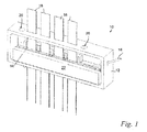
- FIG. 1 schematically shows a partially cut-away view of a silicon ribbon crystal growth furnace 10 that may implement illustrative embodiments of the invention.
- the furnace 10 has, among other things, a housing 12 forming a sealed interior that is substantially free of oxygen (to prevent combustion). Instead of oxygen, the interior has some concentration of another gas, such as argon, or a combination of gasses.
- the housing interior also contains, among other things, a crucible 14 and other components for substantially simultaneously growing four silicon ribbon crystals 16.
- the ribbon crystals 16 may be any of a wide variety of crystal types, such as multi-crystalline, single crystalline, polycrystalline, microcrystalline or semi-crystalline.
- a feed inlet 18 in the housing 12 provides a means for directing silicon feedstock to the interior crucible 14, while an optional window 16 permits inspection of the interior components.
- silicon ribbon crystals 16 is illustrative and not intended to limit all embodiments of the invention.
- the crystals 16 may be formed from a material other than silicon, or a combination of silicon and some other material.
- An interior platform 20 within the housing 20 supports the crucible 14.
- This embodiment of the crucible 14 has an elongated shape with a region for growing silicon ribbon crystals 16 in a side-by-side arrangement along its length.
- the crucible 14 is formed from graphite and resistively heated to a temperature capable of maintaining silicon above its melting point.
- the crucible 14 has a length that is much greater than its width.
- the length of the crucible 14 may be three or more times greater than its width.
- the crucible 14 is not elongated in this manner.
- the crucible 14 may have a somewhat square shape, or a nonrectangular shape. String holes (not shown) through the crucible 14 enable strings to pass through molten silicon and thus, form the crystals 16.
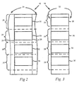
- FIG 2 schematically shows an example of a string ribbon crystal 16 produced by the furnace 10 shown in Figure 1 .
- This ribbon crystal 16 still has its original edges 24, which were formed as the crystal 16 was slowly drawn from the molten silicon in the crucible 14.
- the edges 24 of the ribbon crystal 16, which are not drawn to scale, are irregularly shaped. In some embodiments, however, the original edges 24 are not irregularly shaped. Instead, in such embodiments, the edges 24 are generally planar and generally parallel with the strings 26 (discussed immediately below) of the ribbon crystal 16.
- Figure 2 also shows a pair of strings 26, which normally are encapsulated by the silicon. Although the drawing shows what appears to be a significant area between the strings 26 and their respective edges 24, it is anticipated that the strings 26 will be very close to their respective edges 24 and thus, effectively form the edges 24.
- Figure 2 also shows dashed lines identifying the boundary of wafers 28 ultimately to be produced. Conventional methods cut along the dashed lines to form each wafer 28.
- Each wafer 28 also has a back-surface contact 30. As its name suggests, the back-surface contacts 30 are formed on a side of the ribbon crystal 16 that ultimately will be the back surface of the wafers 28 (i.e., if used as a solar cell).
- edges 24 of prior art ribbon crystals reduced the mobility for carriers within wafers 28 ultimately formed from the ribbon crystal 16.
- a prior art ribbon crystal would be less electrically efficient than it would be if it did not have such edges 24.
- the inventor took an approach that is contrary to what they understood to be the conventional wisdom - they removed at least a portion of the edge 24.
- the inventor removed many of the smaller grains, which produce a high concentration of grain boundaries.
- removal of the edges 24 improved the electrical efficiency in solar cells (e.g., carrier mobility), which is critical in the viability of photovoltaics.
- edge 24 removes a significant amount of the polysilicon, which currently is in low supply and has a corresponding high cost. The inventor nevertheless was surprised to discover that resultant efficiency improvements more than offset the costs associated with material loss caused by edge removal.
- edge 24 requires an additional process step or a plurality of additional steps, further increasing production costs.
- additional steps/cuts required to perform this process increase the likelihood of crystal breakage, thus reducing yield.
- the inventor believes that reducing the width of the ribbon crystal 16, and/or removing the string 26, can lead to additional breakage/yield problems. Despite these and other obstacles teaching away from their solution, the inventor removed the edges 24 to discover the improved benefits.
- a grain is considered to be "large” when it has a smallest outer dimension that is greater than about two times the diffusion length of carriers (e.g., holes and electrons) within the crystal 16.
- carriers e.g., holes and electrons
- grains having a smallest outer dimension of between about 2-5 times the diffusion length of the carriers should suffice.
- Grains having smallest outer dimensions of greater than three times should provide even better results. In fact, it is anticipated that larger grain sizes, even five or more times the carrier diffusion length, should provide even better results.
- the substantial majority of all grains remaining in the crystal 16 are large grains-leaving only trace amounts of small grains.
- the removal step preferably removes a majority of the small grains, which generally concentrate around the string 26.
- Figure 3 schematically shows the ribbon crystal 16 of Figure 2 with both of its edges 24 removed.
- the (new) edges (identified by reference number 32) of the ribbon crystal 16 are substantially planar. In alternative embodiments, however, the new edge 32 may be a non-planar shape, or irregularly shaped. In either case, the ribbon crystal 16 of Figure 3 has substantially no small grains or very few small grains when compared to the ribbon crystal 16 before the edge 24 is removed.
- the back-surface contacts 30 each extend to the new edge 32 of the ribbon crystal 16.
- the ribbon crystals 16 in Figures 2 and 3 are illustrative of but one of a number of different embodiments.
- the back-surface contact 30 may be added after the ribbons are separated/cut into individual wafers 28, and/or not extend to the new edge 32.
- only one edge 24 may be removed, and/or the edge 24 may be removed after the ribbon crystal 16 is separated/cut into individual wafers 28.
- Those skilled in the art may select the appropriate combinations of features based on the ultimate processing and application requirements and preferences.
- Figure 4 shows a method of forming a wafer 28 in accordance with illustrative embodiments of the invention. It should be noted that this method is a simplified summary of the overall process of forming a wafer 28 and thus, does not include a number of other steps that may be included, such as wafer testing and preparation of certain equipment and the silicon. Moreover, some steps may be performed in a different order or, in some instances, omitted.
- the method begins while a ribbon crystal growth furnace 10 draws a ribbon crystal 16 from a molten material. Specifically, at step 400, the method determines if the back-surface contact 30 is to be added to the ribbon crystal 16 before or after removing one or both of the edges 24 (for simplicity, this method refers to one or both edges 24 in the singular; as an "edge 24"). In some instances, if it is formed after removing the edge 24, the back-surface contact 30 undesirably may extend around the new edge 32, which could cause a short circuit. Consideration of this possibility therefore should be used in making this determination.
- step 400 determines that the back-surface contact 30 is to be formed first, then the method continues to step 402, which adds the back-surface contact 30 to the ribbon crystal 16.
- conventional processes may screen print the back-surface contact 30 on one side of the ribbon crystal 16.
- the back-surface contact 30 may be screen printed onto the ribbon crystal 16 as a plurality of separate blocks, as shown in Figures 2 and 3 , or as a solid block spanning more than one wafer 28.
- the method determines at step 404 if the edge(s) 24 should be removed while in the form of a ribbon crystal. In other words, the method may remove the edge(s) 24 either before or after the ribbon crystal 16 is separated into individual wafers 28.
- the method separates the ribbon crystal 16 along the dashed lines of Figure 2 to form individual wafers 28 (step 406).
- the conventional sawing or dicing processes may cut the ribbon along the dashed lines shown in Figures 2 and 3 .
- a laser may cut along the dashed lines as discussed in the above incorporated patent application.
- step 408 removes one or both edges 24 of the ribbon crystal 16 (if continuing from step 404) or the wafers 28 (if continuing from step 406).
- conventional sawing/dicing processes may remove the entire string 26 and many other smaller grains inward of the string (if any).
- Experimental processes may determine how far to remove the edge 24 inward of the string 26.
- the removal device e.g., a laser or saw
- the string 26 may not be positioned perfectly straight from top to bottom of the crystal 16.
- the string may be more straight than the cut.
- the removal step may leave a portion of the string 26 behind in the crystal 16.
- one skilled in the art can select an appropriate distance to cut the ribbon crystal 16 (or wafer 28, as the case may be) inward from the string.
- one skilled in the art can set the width of the crystal 16 and measure outwardly from a generally longitudinal point of the crystal 16. For example, to yield a crystal 16 with about a 100 millimeter width, one skilled in the art can cut along generally parallel lines about 50 millimeters from a general longitudinal portion of the crystal 16.
- the ribbon crystal 16 is grown to have a significant amount of area outward of the string 26, then some embodiments may remove a portion of the crystal 16 outward of the string 26, thus keeping the string 26 in the crystal 16. It nevertheless is anticipated that removal of the string 26 in such a crystal 16 will yield more efficient wafers. It should be noted that a wafer produced by the discussed techniques and in the described manners is considered to be a string ribbon wafer even if the string 26 is partially or completely removed.
- the method may perform step 408 in a number of different manners. Specifically, if removing the edge(s) 24 while in ribbon crystal form, the method may automate the process as the ribbon crystal 16 grows.
- the furnace 10 may be retrofitted to include a saw or laser (not shown) to remove the edge(s) 24 from the growing ribbon crystal 16 in real time.
- the ribbon crystal 16 first may be manually scribed to remove it from the furnace 10, and then manually or automatically moved to another machine that cuts the edge(s) 24 in the prescribed manner.
- some embodiments remove the edge(s) 24 by means of an operator manually scribing the edge(s) 24 of the ribbon crystal 16.
- the method may use either automatic or manual means to remove the edge(s) 24.
- removal of one or both edges 24 removes the smaller grains (i.e., the area with high grain density). This should leave relatively larger grains in the resulting wafers 28, which improves electrical efficiency.
- the method concludes by adding the back-surface contact 30 to the ribbon crystal 16 or wafers 28, depending on their form, if such feature was not already added (step 410), and separating the ribbon crystal 16 into wafers 28 if not already in that form (step 412).
- the back-surface contact 30 may be formed at a number of different points in the overall fabrication of a solar cell.
- the method could add the back-surface contact 30 before any fabrication steps are executed, or add the back-surface contact 30 after performing a number of solar cell fabrication steps that were not discussed.
- planar edges 32 with few or no grain boundary regions.
- These planar edges 32 may form approximately ninety degree angles with their adjacent sides (i.e., the intersection of the top edge and the new side edge 32 of the ultimate wafers 28).
- these planar edges 32 may form acute and/or obtuse angles with their adjacent sides.
- such embodiments may form new edges 32 having a variety of shapes (e.g., irregularly shaped).
- many such wafers 28 should 1) have improved electrical properties due to removal of many of the high grain concentrations near the crystal edge, 2) may be positioned in closer proximity to neighboring wafers, and 3) maximize the area of a back-surface contact 30.
Landscapes
- Chemical & Material Sciences (AREA)
- Engineering & Computer Science (AREA)
- Crystallography & Structural Chemistry (AREA)
- Materials Engineering (AREA)
- Metallurgy (AREA)
- Organic Chemistry (AREA)
- Crystals, And After-Treatments Of Crystals (AREA)
- Photovoltaic Devices (AREA)
- Processing Of Stones Or Stones Resemblance Materials (AREA)
- Silicon Compounds (AREA)
- Mechanical Treatment Of Semiconductor (AREA)
Applications Claiming Priority (2)
| Application Number | Priority Date | Filing Date | Title |
|---|---|---|---|
| US95243507P | 2007-07-27 | 2007-07-27 | |
| PCT/US2008/071179 WO2009018145A1 (en) | 2007-07-27 | 2008-07-25 | Wafer/ribbon crystal method and apparatus |
Publications (2)
| Publication Number | Publication Date |
|---|---|
| EP2195475A1 EP2195475A1 (en) | 2010-06-16 |
| EP2195475B1 true EP2195475B1 (en) | 2012-11-14 |
Family
ID=39791565
Family Applications (1)
| Application Number | Title | Priority Date | Filing Date |
|---|---|---|---|
| EP08782387A Not-in-force EP2195475B1 (en) | 2007-07-27 | 2008-07-25 | Wafer/ribbon crystal and method for its manufacture |
Country Status (9)
| Country | Link |
|---|---|
| US (1) | US20090025787A1 (enExample) |
| EP (1) | EP2195475B1 (enExample) |
| JP (1) | JP2010534610A (enExample) |
| KR (1) | KR20100039386A (enExample) |
| CN (1) | CN101688322B (enExample) |
| CA (1) | CA2689519A1 (enExample) |
| ES (1) | ES2399465T3 (enExample) |
| MY (1) | MY150483A (enExample) |
| WO (1) | WO2009018145A1 (enExample) |
Families Citing this family (4)
| Publication number | Priority date | Publication date | Assignee | Title |
|---|---|---|---|---|
| CN101443888B (zh) * | 2006-03-13 | 2011-03-16 | 内诺格雷姆公司 | 薄硅或者锗片以及由薄片形成的光电池 |
| US20120164379A1 (en) * | 2010-12-22 | 2012-06-28 | Evergreen Solar, Inc. | Wide Sheet Wafer |
| US8912083B2 (en) | 2011-01-31 | 2014-12-16 | Nanogram Corporation | Silicon substrates with doped surface contacts formed from doped silicon inks and corresponding processes |
| US10584592B2 (en) * | 2015-11-23 | 2020-03-10 | United Technologies Corporation | Platform for an airfoil having bowed sidewalls |
Family Cites Families (17)
| Publication number | Priority date | Publication date | Assignee | Title |
|---|---|---|---|---|
| US4661200A (en) * | 1980-01-07 | 1987-04-28 | Sachs Emanuel M | String stabilized ribbon growth |
| US4689109A (en) * | 1980-12-11 | 1987-08-25 | Sachs Emanuel M | String stabilized ribbon growth a method for seeding same |
| FR2516708A1 (fr) | 1981-11-13 | 1983-05-20 | Comp Generale Electricite | Procede de fabrication de silicium polycristallin pour photopiles solaires |
| US4711695A (en) * | 1983-05-19 | 1987-12-08 | Mobil Solar Energy Corporation | Apparatus for and method of making crystalline bodies |
| JPS62108797A (ja) | 1985-11-07 | 1987-05-20 | Toshiba Corp | 帯状結晶製造装置 |
| JPS62123092A (ja) * | 1985-11-21 | 1987-06-04 | Toshiba Corp | 平板状シリコン結晶の成長装置 |
| US5122504A (en) * | 1990-02-27 | 1992-06-16 | The Board Of Trustees Of The Leland Stanford Junior University | Superconducting ribbon process using laser heating |
| USRE36156E (en) * | 1992-10-09 | 1999-03-23 | Astropower, Inc. | Columnar-grained polycrystalline solar cell and process of manufacture |
| JP4079548B2 (ja) * | 1999-04-30 | 2008-04-23 | 株式会社荏原製作所 | 結晶の連続引き上げ装置 |
| JP2001122696A (ja) * | 1999-10-21 | 2001-05-08 | Matsushita Seiko Co Ltd | リボンシリコンウェハの製造方法 |
| US6376797B1 (en) * | 2000-07-26 | 2002-04-23 | Ase Americas, Inc. | Laser cutting of semiconductor materials |
| US6423928B1 (en) * | 2000-10-12 | 2002-07-23 | Ase Americas, Inc. | Gas assisted laser cutting of thin and fragile materials |
| JP2003267716A (ja) * | 2002-03-13 | 2003-09-25 | Sharp Corp | 多結晶半導体基板製造装置およびその装置を用いる多結晶半導体基板の製造方法 |
| US7162874B2 (en) * | 2004-07-30 | 2007-01-16 | Hija Holding B.V. | Apparatus and method for gas turbine engine fuel/air premixer exit velocity control |
| CN100539206C (zh) * | 2005-09-23 | 2009-09-09 | 中芯国际集成电路制造(上海)有限公司 | 可以充分吸收更广泛波长太阳光的太阳能电池结构 |
| US7572334B2 (en) * | 2006-01-03 | 2009-08-11 | Applied Materials, Inc. | Apparatus for fabricating large-surface area polycrystalline silicon sheets for solar cell application |
| CN100416863C (zh) * | 2006-10-13 | 2008-09-03 | 中国科学院上海技术物理研究所 | 廉价多晶硅薄膜太阳电池 |
-
2008
- 2008-07-25 EP EP08782387A patent/EP2195475B1/en not_active Not-in-force
- 2008-07-25 ES ES08782387T patent/ES2399465T3/es active Active
- 2008-07-25 JP JP2010518410A patent/JP2010534610A/ja active Pending
- 2008-07-25 US US12/179,972 patent/US20090025787A1/en not_active Abandoned
- 2008-07-25 CN CN200880023563.5A patent/CN101688322B/zh not_active Expired - Fee Related
- 2008-07-25 MY MYPI20100162 patent/MY150483A/en unknown
- 2008-07-25 KR KR1020107002383A patent/KR20100039386A/ko not_active Ceased
- 2008-07-25 WO PCT/US2008/071179 patent/WO2009018145A1/en not_active Ceased
- 2008-07-25 CA CA002689519A patent/CA2689519A1/en not_active Abandoned
Also Published As
| Publication number | Publication date |
|---|---|
| CN101688322A (zh) | 2010-03-31 |
| KR20100039386A (ko) | 2010-04-15 |
| US20090025787A1 (en) | 2009-01-29 |
| WO2009018145A1 (en) | 2009-02-05 |
| EP2195475A1 (en) | 2010-06-16 |
| CA2689519A1 (en) | 2009-02-05 |
| MY150483A (en) | 2014-01-30 |
| ES2399465T3 (es) | 2013-04-01 |
| CN101688322B (zh) | 2013-03-27 |
| JP2010534610A (ja) | 2010-11-11 |
Similar Documents
| Publication | Publication Date | Title |
|---|---|---|
| CN1243602A (zh) | 制备薄硅膜的方法 | |
| EP4663822A1 (en) | Monocrystalline silicon rod and silicon wafer prepared therefrom, and battery, battery string and solar module | |
| EP2195475B1 (en) | Wafer/ribbon crystal and method for its manufacture | |
| KR20100015302A (ko) | 실리콘 기재의 가공 방법과 그 가공품 및 가공 장치 | |
| WO2012036002A1 (ja) | 太陽電池及びその製造方法 | |
| EP1485956B2 (en) | Process of producing multicrystalline silicon substrate | |
| KR100911622B1 (ko) | 태양전지 단결정 실리콘 잉곳의 절단방법 | |
| US12359343B2 (en) | Wafer with regions of low oxygen concentration | |
| Green | Developments in crystalline silicon solar cells | |
| Hu et al. | Effects of metal impurities at the edges of cast Si ingot on crystal quality and solar cell performance | |
| CN112847851A (zh) | 一种单晶硅棒的加工方法、硅片、电池片和光伏组件 | |
| US20100055412A1 (en) | String With Refractory Metal Core For String Ribbon Crystal Growth | |
| JP2004140087A (ja) | 太陽電池用多結晶シリコン基板とその製造法、及びこの基板を用いた太陽電池の製造法 | |
| Stoddard et al. | Evaluating BP Solar's Mono 2™ material: Lifetime and cell electrical data | |
| US8969183B2 (en) | Method for producing thin layers of crystalline or polycrystalline materials | |
| Rost et al. | Float zone (FZ) silicon: A potential material for advanced commercial solar cells? | |
| Seren et al. | Ribbon Growth on Substrate and Molded Wafer-Two low cost silicon ribbon materials for PV | |
| Pinto et al. | Zone melting recrystallization of self supported silicon ribbons obtained by fast cvd from silane | |
| US20250389050A1 (en) | Wafer with regions of low oxygen concentration | |
| JP5320376B2 (ja) | 多結晶型シリコン太陽電池パネルの製造方法 | |
| Schwirtlich | EFG ribbon technology | |
| US20250389046A1 (en) | Monocrystalline silicon ingot and silicon wafer prepared therefrom, cell, cell string, and solar module | |
| Muller et al. | Silicon for photovoltaics | |
| JP2006210395A (ja) | 太陽電池用多結晶シリコン基板の作製方法 | |
| Schonecker et al. | Compatibility of the RGS silicon wafer with industrial type solar cell processing |
Legal Events
| Date | Code | Title | Description |
|---|---|---|---|
| PUAI | Public reference made under article 153(3) epc to a published international application that has entered the european phase |
Free format text: ORIGINAL CODE: 0009012 |
|
| 17P | Request for examination filed |
Effective date: 20091217 |
|
| AK | Designated contracting states |
Kind code of ref document: A1 Designated state(s): AT BE BG CH CY CZ DE DK EE ES FI FR GB GR HR HU IE IS IT LI LT LU LV MC MT NL NO PL PT RO SE SI SK TR |
|
| AX | Request for extension of the european patent |
Extension state: AL BA MK RS |
|
| DAX | Request for extension of the european patent (deleted) | ||
| 17Q | First examination report despatched |
Effective date: 20110819 |
|
| GRAP | Despatch of communication of intention to grant a patent |
Free format text: ORIGINAL CODE: EPIDOSNIGR1 |
|
| GRAS | Grant fee paid |
Free format text: ORIGINAL CODE: EPIDOSNIGR3 |
|
| GRAA | (expected) grant |
Free format text: ORIGINAL CODE: 0009210 |
|
| RAP1 | Party data changed (applicant data changed or rights of an application transferred) |
Owner name: MAX ERA, INC. |
|
| AK | Designated contracting states |
Kind code of ref document: B1 Designated state(s): AT BE BG CH CY CZ DE DK EE ES FI FR GB GR HR HU IE IS IT LI LT LU LV MC MT NL NO PL PT RO SE SI SK TR |
|
| REG | Reference to a national code |
Ref country code: GB Ref legal event code: FG4D |
|
| REG | Reference to a national code |
Ref country code: AT Ref legal event code: REF Ref document number: 584072 Country of ref document: AT Kind code of ref document: T Effective date: 20121115 Ref country code: CH Ref legal event code: EP |
|
| REG | Reference to a national code |
Ref country code: IE Ref legal event code: FG4D |
|
| REG | Reference to a national code |
Ref country code: DE Ref legal event code: R096 Ref document number: 602008020136 Country of ref document: DE Effective date: 20130110 |
|
| REG | Reference to a national code |
Ref country code: ES Ref legal event code: FG2A Ref document number: 2399465 Country of ref document: ES Kind code of ref document: T3 Effective date: 20130401 |
|
| REG | Reference to a national code |
Ref country code: NL Ref legal event code: VDEP Effective date: 20121114 |
|
| REG | Reference to a national code |
Ref country code: AT Ref legal event code: MK05 Ref document number: 584072 Country of ref document: AT Kind code of ref document: T Effective date: 20121114 |
|
| REG | Reference to a national code |
Ref country code: LT Ref legal event code: MG4D |
|
| PG25 | Lapsed in a contracting state [announced via postgrant information from national office to epo] |
Ref country code: SE Free format text: LAPSE BECAUSE OF FAILURE TO SUBMIT A TRANSLATION OF THE DESCRIPTION OR TO PAY THE FEE WITHIN THE PRESCRIBED TIME-LIMIT Effective date: 20121114 Ref country code: HR Free format text: LAPSE BECAUSE OF FAILURE TO SUBMIT A TRANSLATION OF THE DESCRIPTION OR TO PAY THE FEE WITHIN THE PRESCRIBED TIME-LIMIT Effective date: 20121114 Ref country code: LT Free format text: LAPSE BECAUSE OF FAILURE TO SUBMIT A TRANSLATION OF THE DESCRIPTION OR TO PAY THE FEE WITHIN THE PRESCRIBED TIME-LIMIT Effective date: 20121114 Ref country code: FI Free format text: LAPSE BECAUSE OF FAILURE TO SUBMIT A TRANSLATION OF THE DESCRIPTION OR TO PAY THE FEE WITHIN THE PRESCRIBED TIME-LIMIT Effective date: 20121114 Ref country code: NO Free format text: LAPSE BECAUSE OF FAILURE TO SUBMIT A TRANSLATION OF THE DESCRIPTION OR TO PAY THE FEE WITHIN THE PRESCRIBED TIME-LIMIT Effective date: 20130214 |
|
| PG25 | Lapsed in a contracting state [announced via postgrant information from national office to epo] |
Ref country code: SI Free format text: LAPSE BECAUSE OF FAILURE TO SUBMIT A TRANSLATION OF THE DESCRIPTION OR TO PAY THE FEE WITHIN THE PRESCRIBED TIME-LIMIT Effective date: 20121114 Ref country code: LV Free format text: LAPSE BECAUSE OF FAILURE TO SUBMIT A TRANSLATION OF THE DESCRIPTION OR TO PAY THE FEE WITHIN THE PRESCRIBED TIME-LIMIT Effective date: 20121114 Ref country code: PT Free format text: LAPSE BECAUSE OF FAILURE TO SUBMIT A TRANSLATION OF THE DESCRIPTION OR TO PAY THE FEE WITHIN THE PRESCRIBED TIME-LIMIT Effective date: 20130314 Ref country code: GR Free format text: LAPSE BECAUSE OF FAILURE TO SUBMIT A TRANSLATION OF THE DESCRIPTION OR TO PAY THE FEE WITHIN THE PRESCRIBED TIME-LIMIT Effective date: 20130215 Ref country code: BE Free format text: LAPSE BECAUSE OF FAILURE TO SUBMIT A TRANSLATION OF THE DESCRIPTION OR TO PAY THE FEE WITHIN THE PRESCRIBED TIME-LIMIT Effective date: 20121114 Ref country code: PL Free format text: LAPSE BECAUSE OF FAILURE TO SUBMIT A TRANSLATION OF THE DESCRIPTION OR TO PAY THE FEE WITHIN THE PRESCRIBED TIME-LIMIT Effective date: 20121114 |
|
| PG25 | Lapsed in a contracting state [announced via postgrant information from national office to epo] |
Ref country code: AT Free format text: LAPSE BECAUSE OF FAILURE TO SUBMIT A TRANSLATION OF THE DESCRIPTION OR TO PAY THE FEE WITHIN THE PRESCRIBED TIME-LIMIT Effective date: 20121114 |
|
| PG25 | Lapsed in a contracting state [announced via postgrant information from national office to epo] |
Ref country code: DK Free format text: LAPSE BECAUSE OF FAILURE TO SUBMIT A TRANSLATION OF THE DESCRIPTION OR TO PAY THE FEE WITHIN THE PRESCRIBED TIME-LIMIT Effective date: 20121114 Ref country code: SK Free format text: LAPSE BECAUSE OF FAILURE TO SUBMIT A TRANSLATION OF THE DESCRIPTION OR TO PAY THE FEE WITHIN THE PRESCRIBED TIME-LIMIT Effective date: 20121114 Ref country code: EE Free format text: LAPSE BECAUSE OF FAILURE TO SUBMIT A TRANSLATION OF THE DESCRIPTION OR TO PAY THE FEE WITHIN THE PRESCRIBED TIME-LIMIT Effective date: 20121114 Ref country code: CZ Free format text: LAPSE BECAUSE OF FAILURE TO SUBMIT A TRANSLATION OF THE DESCRIPTION OR TO PAY THE FEE WITHIN THE PRESCRIBED TIME-LIMIT Effective date: 20121114 Ref country code: BG Free format text: LAPSE BECAUSE OF FAILURE TO SUBMIT A TRANSLATION OF THE DESCRIPTION OR TO PAY THE FEE WITHIN THE PRESCRIBED TIME-LIMIT Effective date: 20130214 |
|
| PG25 | Lapsed in a contracting state [announced via postgrant information from national office to epo] |
Ref country code: RO Free format text: LAPSE BECAUSE OF FAILURE TO SUBMIT A TRANSLATION OF THE DESCRIPTION OR TO PAY THE FEE WITHIN THE PRESCRIBED TIME-LIMIT Effective date: 20121114 Ref country code: NL Free format text: LAPSE BECAUSE OF FAILURE TO SUBMIT A TRANSLATION OF THE DESCRIPTION OR TO PAY THE FEE WITHIN THE PRESCRIBED TIME-LIMIT Effective date: 20121114 |
|
| PLBE | No opposition filed within time limit |
Free format text: ORIGINAL CODE: 0009261 |
|
| STAA | Information on the status of an ep patent application or granted ep patent |
Free format text: STATUS: NO OPPOSITION FILED WITHIN TIME LIMIT |
|
| 26N | No opposition filed |
Effective date: 20130815 |
|
| PGFP | Annual fee paid to national office [announced via postgrant information from national office to epo] |
Ref country code: ES Payment date: 20130722 Year of fee payment: 6 Ref country code: DE Payment date: 20130927 Year of fee payment: 6 |
|
| PG25 | Lapsed in a contracting state [announced via postgrant information from national office to epo] |
Ref country code: CY Free format text: LAPSE BECAUSE OF FAILURE TO SUBMIT A TRANSLATION OF THE DESCRIPTION OR TO PAY THE FEE WITHIN THE PRESCRIBED TIME-LIMIT Effective date: 20121114 |
|
| PGFP | Annual fee paid to national office [announced via postgrant information from national office to epo] |
Ref country code: FR Payment date: 20130730 Year of fee payment: 6 |
|
| REG | Reference to a national code |
Ref country code: DE Ref legal event code: R097 Ref document number: 602008020136 Country of ref document: DE Effective date: 20130815 |
|
| PGFP | Annual fee paid to national office [announced via postgrant information from national office to epo] |
Ref country code: IT Payment date: 20130729 Year of fee payment: 6 |
|
| PG25 | Lapsed in a contracting state [announced via postgrant information from national office to epo] |
Ref country code: MC Free format text: LAPSE BECAUSE OF FAILURE TO SUBMIT A TRANSLATION OF THE DESCRIPTION OR TO PAY THE FEE WITHIN THE PRESCRIBED TIME-LIMIT Effective date: 20121114 |
|
| REG | Reference to a national code |
Ref country code: CH Ref legal event code: PL |
|
| GBPC | Gb: european patent ceased through non-payment of renewal fee |
Effective date: 20130725 |
|
| REG | Reference to a national code |
Ref country code: IE Ref legal event code: MM4A |
|
| PG25 | Lapsed in a contracting state [announced via postgrant information from national office to epo] |
Ref country code: CH Free format text: LAPSE BECAUSE OF NON-PAYMENT OF DUE FEES Effective date: 20130731 Ref country code: GB Free format text: LAPSE BECAUSE OF NON-PAYMENT OF DUE FEES Effective date: 20130725 Ref country code: LI Free format text: LAPSE BECAUSE OF NON-PAYMENT OF DUE FEES Effective date: 20130731 |
|
| PG25 | Lapsed in a contracting state [announced via postgrant information from national office to epo] |
Ref country code: IE Free format text: LAPSE BECAUSE OF NON-PAYMENT OF DUE FEES Effective date: 20130725 |
|
| REG | Reference to a national code |
Ref country code: DE Ref legal event code: R119 Ref document number: 602008020136 Country of ref document: DE |
|
| REG | Reference to a national code |
Ref country code: FR Ref legal event code: ST Effective date: 20150331 |
|
| PG25 | Lapsed in a contracting state [announced via postgrant information from national office to epo] |
Ref country code: DE Free format text: LAPSE BECAUSE OF NON-PAYMENT OF DUE FEES Effective date: 20150203 Ref country code: IT Free format text: LAPSE BECAUSE OF NON-PAYMENT OF DUE FEES Effective date: 20140725 |
|
| REG | Reference to a national code |
Ref country code: DE Ref legal event code: R119 Ref document number: 602008020136 Country of ref document: DE Effective date: 20150203 |
|
| PG25 | Lapsed in a contracting state [announced via postgrant information from national office to epo] |
Ref country code: FR Free format text: LAPSE BECAUSE OF NON-PAYMENT OF DUE FEES Effective date: 20140731 |
|
| PG25 | Lapsed in a contracting state [announced via postgrant information from national office to epo] |
Ref country code: TR Free format text: LAPSE BECAUSE OF FAILURE TO SUBMIT A TRANSLATION OF THE DESCRIPTION OR TO PAY THE FEE WITHIN THE PRESCRIBED TIME-LIMIT Effective date: 20121114 Ref country code: MT Free format text: LAPSE BECAUSE OF FAILURE TO SUBMIT A TRANSLATION OF THE DESCRIPTION OR TO PAY THE FEE WITHIN THE PRESCRIBED TIME-LIMIT Effective date: 20121114 |
|
| PG25 | Lapsed in a contracting state [announced via postgrant information from national office to epo] |
Ref country code: HU Free format text: LAPSE BECAUSE OF FAILURE TO SUBMIT A TRANSLATION OF THE DESCRIPTION OR TO PAY THE FEE WITHIN THE PRESCRIBED TIME-LIMIT; INVALID AB INITIO Effective date: 20080725 Ref country code: LU Free format text: LAPSE BECAUSE OF NON-PAYMENT OF DUE FEES Effective date: 20130725 |
|
| REG | Reference to a national code |
Ref country code: ES Ref legal event code: FD2A Effective date: 20150826 |
|
| PG25 | Lapsed in a contracting state [announced via postgrant information from national office to epo] |
Ref country code: ES Free format text: LAPSE BECAUSE OF NON-PAYMENT OF DUE FEES Effective date: 20140726 |
|
| PG25 | Lapsed in a contracting state [announced via postgrant information from national office to epo] |
Ref country code: IS Free format text: LAPSE BECAUSE OF FAILURE TO SUBMIT A TRANSLATION OF THE DESCRIPTION OR TO PAY THE FEE WITHIN THE PRESCRIBED TIME-LIMIT Effective date: 20121114 |