EP2194685B1 - Vorrichtung und Verfahren zur Generierung von Signalen - Google Patents
Vorrichtung und Verfahren zur Generierung von Signalen Download PDFInfo
- Publication number
- EP2194685B1 EP2194685B1 EP09177276A EP09177276A EP2194685B1 EP 2194685 B1 EP2194685 B1 EP 2194685B1 EP 09177276 A EP09177276 A EP 09177276A EP 09177276 A EP09177276 A EP 09177276A EP 2194685 B1 EP2194685 B1 EP 2194685B1
- Authority
- EP
- European Patent Office
- Prior art keywords
- data
- unit
- phase rotation
- fourier transform
- inverse fourier
- Prior art date
- Legal status (The legal status is an assumption and is not a legal conclusion. Google has not performed a legal analysis and makes no representation as to the accuracy of the status listed.)
- Active
Links
Images




Classifications
-
- H—ELECTRICITY
- H04—ELECTRIC COMMUNICATION TECHNIQUE
- H04L—TRANSMISSION OF DIGITAL INFORMATION, e.g. TELEGRAPHIC COMMUNICATION
- H04L27/00—Modulated-carrier systems
- H04L27/26—Systems using multi-frequency codes
- H04L27/2601—Multicarrier modulation systems
- H04L27/2602—Signal structure
-
- H—ELECTRICITY
- H04—ELECTRIC COMMUNICATION TECHNIQUE
- H04L—TRANSMISSION OF DIGITAL INFORMATION, e.g. TELEGRAPHIC COMMUNICATION
- H04L27/00—Modulated-carrier systems
- H04L27/26—Systems using multi-frequency codes
- H04L27/2601—Multicarrier modulation systems
- H04L27/2626—Arrangements specific to the transmitter only
- H04L27/2627—Modulators
- H04L27/2628—Inverse Fourier transform modulators, e.g. inverse fast Fourier transform [IFFT] or inverse discrete Fourier transform [IDFT] modulators
Definitions
- the present invention relates to a signal generation device and a signal generation method that induces characteristics of second-order cyclostationarity in a communication system that carries out signal identification based on second-order cyclostationarity.
- Second-order cyclostationarity refers to statistics that generate different characteristics for signals having different parameters, and the use thereof makes it possible to easily identify a plurality of signals having different communication methods.
- Second-order cyclostationarity refers to statistics that generate different characteristics for signals having different parameters, and the use thereof makes it possible to easily identify a plurality of signals having different communication methods.
- a signal generation method that imparts an ID to a wireless signal based on statistics.
- Paragraphs 64 to 73 of the specification of Reference 1 disclose a first wireless signal generation method that induces characteristics of cyclostationarity in a multi-carrier system by transmitting the same symbol for a plurality of prescribed subcarriers.
- paragraph 70 discloses a second wireless signal generation method that uses discrete sine wave symbols as transmitted symbols for a plurality of prescribed subcarriers.
- paragraph 61 discloses a third wireless signal generation method that transmits duplicates of transmission data signals at different frequencies on a frequency axis.
- a wireless signal generation method that induces characteristics of cyclostationarity by duplicating data transmitted by a portion of subcarriers when using an Orthogonal Frequency Division Multiplexing (OFDM) system, and generating transmission signals by controlling input to inverse Fourier transform so that the same data is transmitted by other subcarriers as well.
- OFDM Orthogonal Frequency Division Multiplexing
- the first wireless signal generation method in Reference 1 and the wireless signal generation method of Reference 2 generate signals having characteristics of cyclostationarity corresponding to a prescribed number of remote subcarriers by unifying the transmission signal of a certain subcarrier with signals transmitted by the prescribed number of remote subcarriers from that subcarrier.
- the types of cyclostationarity characteristics that can be induced is limited by the total number of subcarriers, there was the problem of it being difficult to transmit numerous types of information using characteristics of cyclostationarity.
- an object of the present invention is to provide a signal generation device and a signal generation method that secure orthogonality between subcarriers under conditions of employing a transmission method that uses an inverse Fourier transform and induce various characteristics of second-order cyclostationarity with little overhead in a communication system that carries out signal identification based on second-order cyclostationarity.
- the signal generation device as claimed in the present invention is a signal generation device that employs a transmission method that uses an inverse Fourier transform, provided with a modulation unit configured to modulate transmission data to obtain modulation data; a serial-parallel conversion unit configured to convert the modulation data input in series from the modulation unit to parallel data of a prescribed size smaller than the size of the used inverse Fourier transform; a duplication unit configured to select and duplicate all or a portion of the parallel data obtained from the serial-parallel conversion unit, to obtain duplication data; a phase rotation unit configured to rotate the phase of the duplication data at a prescribed rate, to obtain phase rotation data; and an inverse Fourier transform unit configured to carry out inverse Fourier transform on the parallel data obtained from the serial-parallel conversion unit and the phase rotation data obtained from the phase rotation unit.
- the above-mentioned signal generation device is preferably further provided with a rotation rate control unit configured to control the rate of rotation at which the phase of the duplication data is rotated by the phase rotation unit.
- a rotation rate control unit configured to control the rate of rotation at which the phase of the duplication data is rotated by the phase rotation unit.
- the above-mentioned signal generation device is preferably further provided with a duplication target selection control unit configured to control selection of the parallel data targeted for duplication by the duplication unit.
- a duplication target selection control unit configured to control selection of the parallel data targeted for duplication by the duplication unit.
- the signal generation device as claimed in the present invention is a signal generation device that employs a transmission method that uses an inverse Fourier transform, provided with a modulation unit configured to modulate transmission data to obtain modulation data; a serial-parallel conversion unit configured to convert the modulation data input in series from the modulation unit to parallel data of a prescribed size smaller than the size of the used inverse Fourier transform; a phase rotation unit configured to rotate the phase of all of the parallel data obtained from the serial-parallel conversion unit at a prescribed rate to obtain phase rotation data; a subcarrier disposition control unit configured to select all or a portion of the phase rotation data and configured to dispose the selected phase rotation data and the parallel data obtained from the serial-parallel conversion unit to each subcarrier, to obtain disposed parallel data; and an inverse Fourier transform unit configured to carry out inverse Fourier transform on the disposed parallel data.
- the above-mentioned signal generation device is preferably further provided with a rotation rate control unit configured to control the rate of rotation at which the phase of all of the parallel data obtained from the serial-parallel conversion unit is rotated by the phase rotation unit.
- a rotation rate control unit configured to control the rate of rotation at which the phase of all of the parallel data obtained from the serial-parallel conversion unit is rotated by the phase rotation unit.
- the present invention can also be interpreted to be an invention relating to a signal generation method executed by the signal generation devices described above, and can be described in the manner indicated below.
- This signal generation method demonstrates actions and effects that are the same as the respectively corresponding inventions relating to a signal generation device.
- the signal generation method as claimed in the present invention is a signal generation method that is executed by a signal generation device that employs a transmission method that uses an inverse Fourier transform, and includes: a step of modulating transmission data to obtain modulation data; a step of converting the modulation data input in series to parallel data of a prescribed size smaller than the size of the used inverse Fourier transform; a step of selecting and duplicating all or a portion of the parallel data to obtain duplication data; a step of rotating the phase of the duplication data at a prescribed rate, to obtain phase rotation data; and a step of carrying out inverse Fourier transform on the parallel data and the phase rotation data.
- the signal generation method as claimed in the present invention is a signal generation method that is executed by a signal generation device that employs a transmission method that uses an inverse Fourier transform, and includes: a step of modulating transmission data to obtain modulation data; a step of converting the modulation data input in series to parallel data of a prescribed size smaller than the size of the used inverse Fourier transform; a step of rotating the phase of all of the parallel data at a prescribed rate for, to obtain phase rotation data; a step of selecting all or a portion of the phase rotation data and disposing the selected phase rotation data and the parallel data to each subcarrier, to obtain disposed parallel data; and a step of carrying out an inverse Fourier transform on the disposed parallel data.
- diverse second-order cyclostationarity characteristics can be induced with little overhead while ensuring orthogonality between subcarriers under conditions of employing a transmission method that uses an inverse Fourier transform.
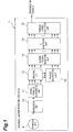
- FIG. 1 is a block diagram representing the functional configuration of a signal generation device in a first embodiment.
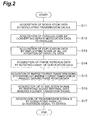
- FIG. 2 is a flow chart showing the procedure of signal generation processing in a first embodiment.
- FIG. 3 is a block diagram representing the functional configuration of a first variation of the signal generation device of FIG 1 .
- FIG. 4 is a block diagram representing the functional configuration of a second variation of the signal generation device of FIG. 1 .
- FIG. 5 is a block diagram representing the functional configuration of a third variation of the signal generation device of FIG. 1 .
- FIG. 6 is a block diagram representing the functional configuration of a signal generation device in a second embodiment.
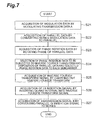
- FIG 7 is a flow chart showing the procedure of signal generation processing in a second embodiment.
- FIG. 8 is a block diagram representing the functional configuration of a variation of the signal generation device of FIG 6 .
- FIG. 9 is a block diagram representing the functional configuration of a signal generation device in the case of using the SC-FDMA method.
- FIG. 10 is a block diagram representing an example of the hardware configuration of signal generation devices in first and second embodiments.
- FIG. 1 is a block diagram representing the functional configuration of a signal generation device 1 in a first embodiment.
- the signal generation device 1 is provided with a modulation unit 10, a serial-parallel conversion unit 11, a duplication unit 12, a phase rotation unit 13, an inverse Fourier transform unit 14, a GI insertion unit 15 and a parallel-series conversion unit 16.
- the modulation unit 10 modulates transmitted data A (to be referred to as "transmission data A") to obtain modulation data.
- modulation refers to a technique for mapping transmission data on a signal space composed of an in-phase component and an orthogonal component in accordance with a modulation method such as phase modulation (such as BPSK or QPSK), amplitude modulation (such as PAM) or quadrature amplitude modulation (QAM).
- phase modulation such as BPSK or QPSK
- amplitude modulation such as PAM
- QAM quadrature amplitude modulation
- X p x 1 , x 2 , ... , x N x N + 1 , x N + 2 , ... , x 2 ⁇ N ⁇ ⁇ ... , ⁇ x ⁇ M / N ⁇ - 1 ⁇ N + 1 , x ⁇ M / N ⁇ - 1 ⁇ N + 2 , ... , x ⁇ M / N ⁇ N .
- N is such that N is always less than N F (N ⁇ N F ) when the size of inverse Fourier transform is N F .
- the duplication unit 12 obtains duplication data by duplicating all or a portion of row data of the matrix given as parallel data. For example, in the case of duplicating data from the first row to the second row of the above-mentioned matrix data, duplication data is generated in the form indicated below.
- X copied x 1 , x 2 x N + 1 , x N + 2 ⁇ ⁇ x ⁇ M / N ⁇ - 1 ⁇ N + 1 , x ⁇ M / N ⁇ - 1 ⁇ N + 2 .
- the phase rotation unit 13 multiplies a phase rotator that undergoes phase rotation at a prescribed angular velocity by each row of duplication data to obtain phase rotation data.
- the rotator when the angular velocity is 2 ⁇ g is represented in the manner indicated below.
- C e j ⁇ 2 ⁇ ⁇ g ⁇ 0 + ⁇ ... 0 e j ⁇ 2 ⁇ ⁇ g ⁇ 1 + ⁇ ⁇ ⁇ ⁇ 0 ... e j ⁇ 2 ⁇ ⁇ g ⁇ ⁇ M / N ⁇ - 1 + ⁇ .
- e j ⁇ ⁇ cos ⁇ + j sin ⁇ and j represents a complex number.
- ⁇ is the initial phase.
- phase rotation data becomes the result of multiplying matrix (4) by matrix (3) starting from the left, and is represented by the following formula (6).
- duplication data is multiplied by the same rotator in formula (6)
- the data may also each be multiplied by separate and independent rotators.
- the angular velocities of rotators corresponding to each row of formula (3) are taken to be 2 ⁇ g 1 and 2 ⁇ g 2
- phase rotation data becomes matrices obtained by coupling those vectors obtained by multiplying the rotator matrix (4) corresponding to angular velocity by each row vectors from the first row to the second row starting from the left side, and is represented in the manner indicated below.
- X rotated x 1 ⁇ e j 2 ⁇ ⁇ g 1 ⁇ 0 , x 2 ⁇ e j 2 ⁇ ⁇ g 2 ⁇ 0 x N + 1 ⁇ e j 2 ⁇ ⁇ g 1 ⁇ 1 , x N + 2 ⁇ e j 2 ⁇ ⁇ g 2 ⁇ 1 ⁇ ⁇ x ⁇ M / N ⁇ - 1 ⁇ N + 1 ⁇ e j ⁇ 2 ⁇ ⁇ g 1 ⁇ ⁇ M / N ⁇ - 1 , x ⁇ M / N ⁇ - 1 ⁇ N + 2 ⁇ e j ⁇ 2 ⁇ ⁇ g 2 ⁇ ⁇ M / N ⁇ - 1 .
- the inverse Fourier transform unit 14 is input with parallel data output from the serial-parallel conversion unit 11 and phase rotation data output from the phase rotation unit 13, subjects the input signals to reverse Fourier transform, and outputs the resulting inverse Fourier transform signals.
- input signals are in the form of the following matrix obtained by coupling, for example, matrices X p and x rotated in the row direction.
- X F . IN X p , X rotated .
- the input matrix size is given by the following: ⁇ M / N ⁇ ⁇ N + 2 .
- the inverse Fourier transform unit 14 subjects the input matrices to inverse fast Fourier transform (IFFT).
- IFFT inverse fast Fourier transform
- the size of the inverse Fourier transform is required to be larger than (N+2).
- N size of the inverse Fourier transform
- F e j ⁇ 2 ⁇ ⁇ ⁇ 0 N + 2 ⁇ 0 e j ⁇ 2 ⁇ ⁇ ⁇ 0 N + 2 ⁇ 1 ... e j ⁇ 2 ⁇ ⁇ ⁇ 0 N + 2 ⁇ N + 1 e j ⁇ 2 ⁇ ⁇ ⁇ 1 N + 2 ⁇ 0 e j ⁇ 2 ⁇ ⁇ ⁇ 1 N + 2 ⁇ 1 ... e j ⁇ 2 ⁇ ⁇ ⁇ 1 N + 2 ⁇ N + 1 ⁇ ⁇ ⁇ e j ⁇ 2 ⁇ ⁇ ⁇ N + 1 N + 2 ⁇ 0 e j ⁇ 2 ⁇ 2 ⁇ ⁇ ⁇ N + 1 N + 2 ⁇ 0 e j ⁇ 2 ⁇ 2 ⁇ ⁇ ⁇ N + 1 N + 2 ⁇ 0 e j ⁇ 2
- X F , OUT X F , IN ⁇ F .
- the inverse Fourier transform signal X F,OUT is a multicarrier signal, and data of the kth row of the input signal matrix X F,IN is transmitted in the kth subcarrier.
- IFFT is carried out after making the number of rows of the input signal matrix equal to the size of the inverse Fourier transform by inserting a zero matrix
- a matrix obtained by coupling matrices X p and X rotated was used for the input signal to the inverse Fourier transform unit 14 in the above-mentioned example
- a form may also be employed in which, for example, matrix X rotated is inserted between a prescribed row of matrix X p and a row adjacent thereto.
- the input signal becomes, for example, as shown below.
- X F , IN X p 1 n , X rotated , X p n + 1 , N .
- n is an integer equal to or less than (N-1)
- X p m l x m , ... , x l x N + m , ... , x N + l ⁇ ... , ⁇ x ⁇ M / N ⁇ - 1 ⁇ N + m , ... , x ⁇ M / N ⁇ - 1 ⁇ N + l .
- a form may also be employed in which matrix X rotated is divided into row vectors, and each row vector is inserted between a prescribed row of X p and a row adjacent thereto in the same manner as (11) above.
- the GI insertion unit 15 duplicates all elements of a prescribed number of rows starting from the matrix farthest to the right (or farthest to the left) of the inverse Fourier transform signals, and by then coupling the duplicated elements to the inverse Fourier transform signals in the row direction starting from the left (or right), a guard interval (GI) is inserted to obtain a GI insertion signal.
- a guard interval For example, if the length of the GI, namely the above-mentioned prescribed number of rows, is taken to be L, then the GI insertion signal becomes as indicated below.
- the parallel-series conversion unit 16 converts a matrix input in the form of a GI insertion signal to series data, and outputs a resulting transmission signal B.
- the transmission signal B is in the following form with respect to the GI insertion signal of formula (13).
- S x 1 F x 2 F ⁇ x ⁇ M / N ⁇ F .
- x k F x k , N - L + 3 F ⁇ x k , N + 2 F x k , 1 F ⁇ x k , N + 2 F .
- transmission signals are output in the form of signals on a time axis in order starting from the first element of formula (15) to the last ⁇ M / N ⁇ N + L + 2 ⁇ th element.
- signals can be generated in which characteristics of cyclostationarity have been induced. Details of the induced cyclostationarity characteristics are described in a subsequent explanation of effects of the present embodiment.
- FIG 2 indicates the procedure relating to signal generation operation in the signal generation device 1.
- the modulation unit 10 of the signal generation device 1 first acquires modulation data by modulating transmission data A (S11 in FIG. 2 ). The modulation data is then input in series to the serial-parallel conversion unit 11. The serial-parallel conversion unit 11 converts series modulation data to parallel to acquire parallel data (S12). Together with the parallel data being input to the duplication unit 12, the parallel data is also input to the inverse Fourier transform unit 14 via the duplication unit 12. The duplication unit 12 then duplicates all or a portion of row data of the input parallel data to acquire duplication data (S 13). The acquired duplication data is then input to the phase rotation unit 13.
- the phase rotation unit 13 then rotates the signal phase of the duplication data by a prescribed angular velocity to acquire phase rotation data (S14).
- the acquired phase rotation data is then input to the inverse Fourier transform unit 14.
- the inverse Fourier transform unit 14 carries out inverse fast Fourier transform (IFFT) on the input parallel data and phase rotation data to acquire an inverse Fourier transform signal (S15).
- the acquired inverse Fourier transform signal is then input to the GI insertion unit 15.
- the GI insertion unit 15 inserts a guard interval (GI) into the inverse Fourier transform signal to acquire a GI insertion signal (S16).
- the acquired GI insertion signal is then input in parallel to the parallel-series conversion unit 16.
- the parallel-series conversion unit 16 converts the GI insertion signal input in parallel to series followed by acquisition and output of a time-domain signal in the form of transmission signal B (S17). This completes processing related to signal generation operation.
- Second-order cyclostationarity refers to a property mainly represented by statistics consisting of a second-order cyclic autocorrelation function (CAF) and spectral correlation density (SCD).
- CAF second-order cyclic autocorrelation function
- SCD spectral correlation density
- SCD becomes as indicated below.
- SCD can be perceived to be a frequency correlation.
- CAF can also be represented as indicated below.
- R x ⁇ ⁇ lim T ⁇ ⁇ ⁇ 1 T ⁇ ⁇ - ⁇ ⁇ ⁇ X T f ⁇ X T * ⁇ f - ⁇ ⁇ e j ⁇ 2 ⁇ ⁇ ⁇ f - ⁇ 2 ⁇ ⁇ ⁇ df .
- characteristics of second-order cyclostationarity can be understood to constitute a correlation between a signal and a signal resulting from shifting the frequency of that signal.
- modulation data transmitted by all or a portion of subcarriers is duplicated, subjected to phase rotation and then transmitted by another subcarrier.
- the ith symbol transmitted by the uth subcarrier is assumed to be a i .
- the transmission signal of the uth subcarrier subjected to Fourier transform is assumed to be A(f).
- phase rotation is applied to the (m+u)th subcarrier, and the ith transmission symbol is a i e j2 ⁇ gi .
- e j2 ⁇ gi is represented as shown below when using a continuous time t.
- e j ⁇ 2 ⁇ ⁇ gi e j ⁇ 2 ⁇ ⁇ g ⁇ / T S ⁇ , i - 1 ⁇ T S ⁇ t ⁇ i ⁇ T S .
- T S is the one symbol time per subcarrier obtained by IFFT and GI insertion.
- e j2 ⁇ gi is a function in which the frequency component (g/T s ) reaches a maximum in the frequency region. Consequently, the signal a i e j2 ⁇ gi transmitted by the (m+u)th subcarrier becomes a signal having as the main component thereof a component in which frequency of a i has been shifted by (g/T s ) on the frequency axis.
- the frequency interval between subcarriers is assumed to be ⁇ f
- the carrier frequency of the uth subcarrier is assumed to be zero.
- A(f) becomes a signal centering on a frequency of 0.
- a transmission signal in the (m+u)th subcarrier can be represented by (cA(f-g/T s )+ ⁇ ).
- c is the amplitude in the frequency component (g/T s ) of e j2 ⁇ gi
- ⁇ is a component originating in a component other than the frequency (g/T s ) generated in e j2 ⁇ gi .
- the transmission signal X(f) based on the central frequency of the uth subcarrier is as indicated below for a sufficient long observation time T.
- the locations of the appearance of a peak for CAF and SCD can be allowed to move, thereby making it possible to induce second-order cyclostationarity characteristics as desired.
- a transmission symbol is input to an IFFT after rotating the phase thereof in the present invention, orthogonality between subcarriers can be maintained in symbol units.
- a conventional demodulation device is sufficient for signal reception (however, a dedicated calculation unit is required to extract cyclostationarity characteristics).
- the present invention induces cyclostationarity by duplicating a transmission signal, at least one subcarrier is enough for inducing cyclstationarity and cyclostationarity can be thus induced with little overhead.
- overhead can be further reduced by limiting the amount of time for inducing cyclostationarity.
- a first variation is configured such that in the duplication unit 12, that rows targeted for duplication in input parallel data are fixed, and symbols of the row targeted for duplication are always input to the phase rotation unit 13. In this case, a portion of the rows of parallel data are always input from the duplication unit 12 to the phase rotation unit 13. Consequently, the duplication unit 12 can be simplified to a configuration in which rows of parallel data targeted for duplication are only distributed by wiring and the like.
- FIG. 3 shows a functional block diagram of the signal generation device 1 in the case of replacing the duplication unit 12 with a simple wiring branch. Furthermore, in the case of simply replacing the duplication unit 12 with a simple wiring branch as shown in FIG.
- a unit for balancing electric power between symbols input to the inverse Fourier transform unit 14 may be inserted between the duplication unit 12 and the inverse Fourier transform unit 14 (or between the duplication unit 12 and the phase rotation unit 13) to prevent this imbalance.
- a distributer and the like may also be provided in the duplication unit 12 so that an imbalance in electric power as described above does not occur.
- a second variation makes it possible to vary cyclostationarity characteristics that appear by varying the angular velocity of phase rotation in the phase rotation unit 13 using the passage of a fixed amount of time such as a frame time or a control signal from the outside. More specifically, as shown in FIG. 4 , a rotation rate control unit 17 is provided in the signal generation device 1, the rotation rate control unit 17 calculates a phase rotation rate in accordance with information of an imparted statistic C determined in advance or determined from the outside in advance in the signal generation device 1, and the phase rotation unit 13 controls the phase rotation rate of a signal based on the calculation result.
- a third variation makes it possible to vary cyclostationarity characteristics that appear by varying rows of parallel data targeted for duplication in the duplication unit 12 using the passage of a fixed amount of time such as a frame time or a control signal from the outside. More specifically, as shown in FIG. 5 , a duplication target selection control unit 18 is further provided in the signal generation device 1, the duplication target selection control unit 18 calculates those rows of parallel data targeted for duplication in accordance with information of an imparted statistic C determined in advance or determined from the outside in advance in the signal generation device 1, and the duplication unit 12 selects the duplication target based on the calculation result serving as control information for selection of duplication targets.
- the signal generation device 1 in the second embodiment shown in FIG 6 has nearly the same configuration as the signal generation device in the previously described first embodiment, it differs in the manner described below.
- the signal generation device 1 in the second embodiment is not provided with the duplication unit 12, and instead all parallel data obtained from the serial-parallel conversion unit 11 is input to the phase rotation unit 13, and the phase rotation unit 13 rotates all of the parallel data obtained from the serial-parallel conversion unit at a prescribed rate to acquire phase rotation data.
- the signal generation device 1 is provided with a subcarrier disposition control unit 19, and this subcarrier disposition control unit 19 selects all or a portion of phase rotation data input from the phase rotation unit 13, disposes the selected phase rotation data and parallel data obtained from the serial-parallel conversion unit 11 to each subcarrier, acquires disposed parallel data and outputs the data to the inverse Fourier transform unit 14.
- FIG. 7 shows the procedure relating to a signal generation operation in the signal generation device 1 of the second embodiment.
- the modulation unit 10 of the signal generation device 1 first acquires modulation data by modulating transmission data A (S21 in FIG. 7 ).
- the modulation data is then input in series to the serial-parallel conversion unit 11.
- the serial-parallel conversion unit 11 converts series modulation data to parallel to acquire parallel data (S22). All acquired parallel data is respectively input to the phase rotation unit 13 and the subcarrier disposition control unit 19.
- the a phase rotation unit 13 rotates the phase of the parallel data signals at a prescribed angular velocity to acquire phase rotation data (S23).
- the acquired phase rotation data is then input to the subcarrier disposition control unit 19.
- the subcarrier disposition control unit 19 selects all or a portion of the input phase rotation data to undergo inverse Fourier transform, and disposes the selected phase rotation data and parallel data acquired by the serial-parallel conversion unit 11 to each subcarrier to acquire disposed parallel data (S24).
- the acquired disposed parallel data is then input to the inverse Fourier transform unit 14.
- the inverse Fourier transform unit 14 carries out inverse fast Fourier transform (IFFT) on the input disposed parallel data to acquire an inverse Fourier transform signal (S25).
- IFFT inverse fast Fourier transform
- the acquired inverse Fourier transform signal is then input to the GI insertion unit 15.
- the GI insertion unit 15 inserts a guard interval (GI) into the inverse Fourier transform signal to acquire a GI insertion signal (S26).
- the acquired GI insertion signal is then input in parallel to the parallel-series conversion unit 16.
- the parallel-series conversion unit 16 converts the GI insertion signal input in parallel to series followed by acquisition and output of a time-domain signal in the form of transmission signal B (S27). This completes processing related to signal generation operation.
- the signal generation device 1 of the second embodiment as described above is configured such that all parallel data acquired with the serial-parallel conversion unit 11 and phase rotation data acquired with the phase rotation unit 13 is input by the subcarrier disposition control unit 19, data to be input to the inverse Fourier transform unit 14 is selected from the phase rotation data, and the selected phase rotation data and the above-mentioned parallel data are disposed to each subcarrier. According to this configuration, disposition of phase rotation data and parallel data can be flexibly altered, enabling ⁇ where the peak of SCD or CAF appears to be set as desired.
- cyclostationarity characteristics that appear may be varied using the passage of a fixed amount of time such as a frame time or a control signal from the outside.
- the rotation rate control unit 17 is provided in the signal generation device 1, the rotation rate control unit 17 calculates a phase rotation rate in accordance with information of an imparted statistic C determined in advance or determined from the outside in advance in the signal generation device 1, and the signal rotation unit 13 controls the phase rotation rate of a signal based on that calculation result.
- the above-mentioned first and second embodiments disclose examples of OFDM systems in which parallel data acquired by the serial-parallel conversion unit 11 is directly inserted into the inverse Fourier transform unit 14, an OFDM system is not required provided the signal generation unit uses an inverse Fourier transform.
- the present invention can also be applied to a single-carrier FDMA (SC-FDMA) system. In this case, in the signal generation device 1 shown in FIG.
- a Fourier transform unit 20 is provided on the output side of the serial-parallel conversion unit 11, parallel data obtained with the serial-parallel conversion unit 11 is subjected to a Fourier transform by the Fourier transform unit 20, and the duplication unit 12 duplicates data that has undergone the Fourier transform and inputs that data to the phase rotation unit 13.
- the a phase rotation unit 13 rotates the phase of the duplicated Fourier transformed data at a prescribed rotation rate and inputs that data in the form of phase rotation data to the inverse Fourier transform unit 14.
- the inverse Fourier transform unit 14 uses the phase rotation data input from the phase rotation unit 13 and the Fourier transformed data input from the Fourier transform unit 20 as an input signal, and carries out an inverse fast Fourier transform (IFFT) on that input signal to acquire an inverse Fourier transform signal. Subsequently, in the same manner as in the first and second embodiments, the inverse Fourier transform signal is inserted with a guard interval (GI) by the GI insertion unit 15 to obtain a GI insertion signal, and the GI insertion signal input in parallel to the parallel-series conversion unit 16 is converted to series by the parallel-series conversion unit 16 and then output as a time-domain signal in the form of a transmission signal B.
- GI guard interval
- SCD or CAF characteristics can be similarly induced in SC-FDMA system signals by employing the configuration shown in FIG 9 .
- the signal generation device 1 in the first embodiment or second embodiment can be configured by a computer system or other arbitrary device capable of storing data.
- the signal generation device 1 can employ a configuration provided with a CPU 31 that executes an operating system or application program and the like, a main storage unit 32 composed of ROM and RAM, an auxiliary storage unit 33 composed of non-volatile memory and the like, an input-output control unit 34 that controls exchange of data with the outside, a display unit 35 composed of a monitor and the like, and an operating unit 36 composed of keys for entering letters and numbers and for instructing execution.
Landscapes
- Engineering & Computer Science (AREA)
- Computer Networks & Wireless Communication (AREA)
- Signal Processing (AREA)
- Physics & Mathematics (AREA)
- Discrete Mathematics (AREA)
- General Physics & Mathematics (AREA)
- Mathematical Physics (AREA)
- Digital Transmission Methods That Use Modulated Carrier Waves (AREA)
- Complex Calculations (AREA)
- Radar Systems Or Details Thereof (AREA)
Claims (7)
- Signal-Erzeugungs-Einrichtung (1), die eine Übertragungs-Methode, die eine inverse Fourier-Transformation verwendet, einsetzt, aufweisend:eine Modulations-Einheit (10), eingerichtet zum Modulieren von Übertragungs-Daten, um Modulations-Daten zu erhalten;eine Seriell-Parallel-Konvertierungs-Einheit (11), eingerichtet zum Konvertieren der in Serie von der Modulations-Einheit (10) eingegebenen Modulations-Daten in parallele Daten einer vorgegebenen Größe kleiner als die Größe der verwendeten inversen Fourier-Transformation;eine Duplikations-Einheit (12), eingerichtet zum Selektieren und Duplizieren aller oder eines Teils der von der Seriell-Parallel-Konvertierungs-Einheit (11) erhaltenen parallelen Daten, um Duplikations-Daten zu erhalten; und gekennzeichnet durch:eine Phasen-Rotations-Einheit (13), eingerichtet zum Rotieren der Phase der Duplikations-Daten mit einer vorgegebenen Phasen-Rotations-Rate, um Phasen-Rotations-Daten zu erhalten; undeine Inverse-Fourier-Transformations-Einheit (14), eingerichtet zum Ausführen von inverser Fourier-Transformation auf den von der Seriell-Parallel-Konvertierungs-Einheit (11) erhaltenen parallelen Daten und den von der Phasen-Rotations-Einheit (13) erhaltenen Phasen-Rotations-Daten.
- Signal-Erzeugungs-Einrichtung (1) gemäß Anspruch 1, ferner aufweisend eine Rotations-Rate-Kontroll-Einheit (17), eingerichtet zum Kontrollieren der Rate von Rotation mit der die Phase der Duplikations-Daten durch die Phasen-Rotations-Einheit (13) rotiert wird.
- Signal-Erzeugungs-Einrichtung (1) gemäß Anspruch 1, ferner aufweisend eine Duplikations-Ziel-Auswahl-Kontroll-Einheit (18), eingerichtet zum Kontrollieren von Selektion der auf Duplikation durch die Duplikations-Einheit (12) gerichteten parallelen Daten.
- Signal-Erzeugungs-Einrichtung (1), die eine Übertragungs-Methode, die eine inverse Fourier-Transformation verwendet, einsetzt, aufweisend:eine Modulations-Einheit (10), eingerichtet zum Modulieren von Übertragungs-Daten, um Modulations-Daten zu erhalten;eine Seriell-Parallel-Konvertierungs-Einheit (11), eingerichtet zum Konvertieren der in Serie von der Modulations-Einheit (10) eingegebenen Modulations-Daten in parallele Daten einer vorgegebenen Größe kleiner als die Größe der verwendeten inversen Fourier-Transformation; und gekennzeichnet durch:eine Phasen-Rotations-Einheit (13), eingerichtet zum Rotieren der Phase von allen von der Seriell-Parallel-Konvertierungs-Einheit (11) erhaltenen parallelen Daten mit einer vorgegebenen Phasen-Rotations-Rate, um Phasen-Rotations-Daten zu erhalten;eine Unter-Träger-Anordnungs-Einheit (19), eingerichtet zum Selektieren aller oder eines Teils der Phasen-Rotations-Daten und eingerichtet zum Anordnen der selektierten Phasen-Rotations-Daten und der von der Seriell-Parallel-Konvertierungs-Einheit (11) erhaltenen parallelen Daten auf jedem Unter-Träger, um angeordnete parallele Daten zu erhalten; undeine Inverse-Fourier-Transformations-Einheit (14), eingerichtet zum Ausführen von inverser Fourier-Transformation auf den angeordneten parallelen Daten.
- Signal-Erzeugungs-Einrichtung (1) gemäß Anspruch 4, ferner aufweisend eine Rotations-Rate-Kontroll-Einheit (17), eingerichtet zum Kontrollieren der Rate von Rotation mit der die Phase aller der von der Seriell-Parallel-Konvertierungs-Einheit (11) erhaltenen parallelen Daten durch die Phasen-Rotations-Einheit (13) rotiert wird.
- Signal-Erzeugungs-Verfahren, ausgeführt von einer Signal-Erzeugungs-Einrichtung (1), die eine Übertragungs-Methode, die eine inverse Fourier-Transformation verwendet, einsetzt, aufweisend die Schritte des:Modulierens (S11) von Übertragungs-Daten, um Modulations-Daten zu erhalten;Konvertierens (S 12) der in Serie eingegebenen Modulations-Daten in parallele Daten einer vorgegebenen Größe kleiner als die Größe der verwendeten inversen Fourier-Transformation;Selektierens und Duplizierens (S 13) aller oder eines Teils der parallelen Daten, um Duplikations-Daten zu erhalten; und gekennzeichnet durch die Schritte des:Rotierens (S 14) der Phase der Duplikations-Daten mit einer vorgegebenen Phasen-Rotations-Rate, um Phasen-Rotations-Daten zu erhalten; undAusführens von inverser Fourier-Transformation (S 15) auf den parallelen Daten und den Phasen-Rotations-Daten.
- Signal-Erzeugungs-Verfahren, ausgeführt von einer Signal-Erzeugungs-Einrichtung (1), die eine Übertragungs-Methode, die eine inverse Fourier-Transformation verwendet, einsetzt, aufweisend die Schritte des:Modulierens (S21) von Übertragungs-Daten, um Modulations-Daten zu erhalten;Konvertierens (S22) der in Serie eingegebenen Modulations-Daten in parallele Daten einer vorgegebenen Größe kleiner als die Größe der verwendeten inversen Fourier-Transformation; und gekennzeichnet durch die Schritte des:Rotierens (S23) der Phase von allen parallelen Daten mit einer vorgegebenen Phasen-Rotations-Rate, um Phasen-Rotations-Daten zu erhalten;Selektierens (S24) aller oder eines Teils der Phasen-Rotations-Daten und Anordnens der selektierten Phasen-Rotations-Daten und der parallelen Daten auf jedem Unter-Träger, um angeordnete parallele Daten zu erhalten; undAusführens von inverser Fourier-Transformation (S25) auf den angeordneten parallelen Daten.
Applications Claiming Priority (1)
| Application Number | Priority Date | Filing Date | Title |
|---|---|---|---|
| JP2008309121A JP5167097B2 (ja) | 2008-12-03 | 2008-12-03 | 信号生成装置及び信号生成方法 |
Publications (2)
| Publication Number | Publication Date |
|---|---|
| EP2194685A1 EP2194685A1 (de) | 2010-06-09 |
| EP2194685B1 true EP2194685B1 (de) | 2011-08-24 |
Family
ID=42102065
Family Applications (1)
| Application Number | Title | Priority Date | Filing Date |
|---|---|---|---|
| EP09177276A Active EP2194685B1 (de) | 2008-12-03 | 2009-11-26 | Vorrichtung und Verfahren zur Generierung von Signalen |
Country Status (5)
| Country | Link |
|---|---|
| US (1) | US8189700B2 (de) |
| EP (1) | EP2194685B1 (de) |
| JP (1) | JP5167097B2 (de) |
| CN (1) | CN101753511B (de) |
| AT (1) | ATE522060T1 (de) |
Families Citing this family (11)
| Publication number | Priority date | Publication date | Assignee | Title |
|---|---|---|---|---|
| JP5236807B2 (ja) * | 2009-06-12 | 2013-07-17 | 三菱電機株式会社 | 通信装置 |
| EP2512049A4 (de) | 2009-12-11 | 2015-12-30 | Fujitsu Ltd | Drahtlose kommunikationsvorrichtung und drahtloses kommunikationsverfahren |
| JP4916561B2 (ja) * | 2010-03-26 | 2012-04-11 | 株式会社エヌ・ティ・ティ・ドコモ | 信号生成装置及び信号生成方法 |
| JP5684498B2 (ja) | 2010-06-15 | 2015-03-11 | 住友重機械工業株式会社 | 射出成形方法及び射出成形機 |
| JP5719192B2 (ja) * | 2011-02-17 | 2015-05-13 | 株式会社Nttドコモ | 無線局、干渉回避方法及びシステム |
| JP2014039128A (ja) * | 2012-08-14 | 2014-02-27 | Sharp Corp | 通信システム、通信装置および通信方法 |
| CN108737316B (zh) * | 2013-03-13 | 2021-04-23 | 三菱电机株式会社 | 发送装置和发送方法 |
| US9667349B1 (en) * | 2015-04-15 | 2017-05-30 | The United States Of America As Represented By The Secretary Of The Navy | Dynamic range extension of heterodyne fiber-optic interferometers via instantaneous carrier measurement |
| CN111200571B (zh) * | 2018-11-19 | 2021-10-01 | 华为技术有限公司 | 一种信号传输方法及装置 |
| CN112187333B (zh) * | 2019-07-05 | 2022-06-14 | 华为技术有限公司 | 信号传输方法及其装置 |
| CN120263380B (zh) * | 2025-06-03 | 2025-10-14 | 新毅东(北京)科技有限公司 | 相位模糊解析方法、解析装置及fpga |
Family Cites Families (14)
| Publication number | Priority date | Publication date | Assignee | Title |
|---|---|---|---|---|
| US20060203927A1 (en) * | 2001-03-27 | 2006-09-14 | Aware, Inc. | Systems and methods for implementing receiver transparent Q-mode |
| KR20040005175A (ko) * | 2002-07-08 | 2004-01-16 | 삼성전자주식회사 | 직교주파수분할다중화 통신시스템에서 선택적매핑의부가정보 송수신 장치 및 방법 |
| DE10325839B4 (de) * | 2003-06-06 | 2012-03-08 | Lantiq Deutschland Gmbh | Verfahren und Schaltung zur Crestfaktor-Reduzierung |
| JP4443991B2 (ja) * | 2004-04-23 | 2010-03-31 | 株式会社エヌ・ティ・ティ・ドコモ | 無線通信システム、受信装置及び受信方法 |
| JP4091578B2 (ja) * | 2004-08-11 | 2008-05-28 | 株式会社東芝 | 無線通信装置及びアンテナ数の推定方法 |
| JP4490831B2 (ja) * | 2005-01-17 | 2010-06-30 | シャープ株式会社 | 無線通信システム、無線通信装置及び無線通信方法 |
| EP1843499B1 (de) * | 2005-01-17 | 2018-04-18 | Sharp Kabushiki Kaisha | Stabile Übertragung und zuverlässiger Empfang von mehreren Signalströmen in einem MIMO-Kommunikationssystem |
| JP2006314081A (ja) * | 2005-04-08 | 2006-11-16 | Matsushita Electric Ind Co Ltd | 通信装置及び通信方法 |
| EP1881629A1 (de) * | 2005-05-30 | 2008-01-23 | Matsushita Electric Industrial Co., Ltd. | Basisstationsgerät und verfahren für drahtlose mehrträger-kommunikation |
| CN101283533A (zh) * | 2005-10-07 | 2008-10-08 | 松下电器产业株式会社 | 无线通信基站装置和导频发送方法 |
| PL1944882T3 (pl) * | 2005-10-31 | 2011-07-29 | Snaptrack Inc | Urządzenie terminala, urządzenie stacji bazowej i system komunikacyjny |
| CN101674121B (zh) * | 2005-12-20 | 2013-10-30 | 华为技术有限公司 | 发送机 |
| JP4247267B2 (ja) | 2006-07-31 | 2009-04-02 | 株式会社エヌ・ティ・ティ・ドコモ | 無線送信機、無線受信機、無線通信システム、及び無線信号制御方法 |
| CN101512945A (zh) * | 2006-09-15 | 2009-08-19 | 富士通株式会社 | 用于通过多载波方式发送信号的装置及方法 |
-
2008
- 2008-12-03 JP JP2008309121A patent/JP5167097B2/ja active Active
-
2009
- 2009-11-26 EP EP09177276A patent/EP2194685B1/de active Active
- 2009-11-26 AT AT09177276T patent/ATE522060T1/de not_active IP Right Cessation
- 2009-11-30 US US12/627,315 patent/US8189700B2/en active Active
- 2009-12-02 CN CN2009102512056A patent/CN101753511B/zh active Active
Also Published As
| Publication number | Publication date |
|---|---|
| ATE522060T1 (de) | 2011-09-15 |
| JP5167097B2 (ja) | 2013-03-21 |
| CN101753511B (zh) | 2013-01-23 |
| EP2194685A1 (de) | 2010-06-09 |
| US20100135433A1 (en) | 2010-06-03 |
| JP2010136028A (ja) | 2010-06-17 |
| US8189700B2 (en) | 2012-05-29 |
| CN101753511A (zh) | 2010-06-23 |
Similar Documents
| Publication | Publication Date | Title |
|---|---|---|
| EP2194685B1 (de) | Vorrichtung und Verfahren zur Generierung von Signalen | |
| EP2725717B1 (de) | Sendevorrichtung, empfangsvorrichtung und kommunikationsverfahren | |
| EP1909424A1 (de) | Datenkommunikationssystem und datenüebrtragungsvorrichtung | |
| US7970085B2 (en) | OFDM transmission and reception for non-OFDMA signals | |
| EP1513279B1 (de) | Datenverschlüsselung in der physikalischen Schicht eines Datenübertragungssystems | |
| CN102904854A (zh) | 一种在滤波器组多载波系统中减小峰均比的方法和装置 | |
| KR20090031361A (ko) | 기지국장치 | |
| KR20090019867A (ko) | 가변대역에서 통신하기 위한 장치 및 방법 | |
| EP2369802B1 (de) | Signalzeugungsvorrichtung und -verfahren mit einem übertragungsverfahren mit fouriertransformation | |
| RU2010150767A (ru) | Устройство связи, способ связи и интегральная схема | |
| JP2012165252A (ja) | 送信機、受信機および通信システム | |
| EP2560305A1 (de) | Ofdm-modulator, ofdm-sendevorrichtung und ofdm-modulationsverfahren | |
| Farhang et al. | SC-FDMA as a delay-Doppler domain modulation technique | |
| CN111866792B (zh) | 一种信号的发送、接收方法及终端 | |
| US10355906B2 (en) | Synchronization device and synchronization method | |
| US8976879B2 (en) | Communication device and communication method | |
| Zhang et al. | Secured chaotic cognitive radio system using advanced encryption standard | |
| Hassan | Increasing the symbol rate in QAM system using a new set of orthonormal basics functions | |
| CN119788481B (zh) | 一种未知ofdm信号帧结构参数的识别方法和系统 | |
| CN101924720B (zh) | 子载波处理方法、装置和系统 | |
| JP4490831B2 (ja) | 無線通信システム、無線通信装置及び無線通信方法 | |
| JP5704079B2 (ja) | 通信機および通信方法 | |
| CN102571678A (zh) | 时域备选信号的选取方法及装置 | |
| WO2007069203A2 (en) | Ofdm system synchronization using correlations with known pilot patterns | |
| WO2025066404A1 (zh) | 数据传输方法、设备及存储介质 |
Legal Events
| Date | Code | Title | Description |
|---|---|---|---|
| PUAI | Public reference made under article 153(3) epc to a published international application that has entered the european phase |
Free format text: ORIGINAL CODE: 0009012 |
|
| 17P | Request for examination filed |
Effective date: 20091126 |
|
| AK | Designated contracting states |
Kind code of ref document: A1 Designated state(s): AT BE BG CH CY CZ DE DK EE ES FI FR GB GR HR HU IE IS IT LI LT LU LV MC MK MT NL NO PL PT RO SE SI SK SM TR |
|
| GRAP | Despatch of communication of intention to grant a patent |
Free format text: ORIGINAL CODE: EPIDOSNIGR1 |
|
| RIC1 | Information provided on ipc code assigned before grant |
Ipc: H04L 27/26 20060101AFI20110128BHEP |
|
| RIN1 | Information on inventor provided before grant (corrected) |
Inventor name: MAEDA, KOJI |
|
| GRAS | Grant fee paid |
Free format text: ORIGINAL CODE: EPIDOSNIGR3 |
|
| GRAA | (expected) grant |
Free format text: ORIGINAL CODE: 0009210 |
|
| AK | Designated contracting states |
Kind code of ref document: B1 Designated state(s): AT BE BG CH CY CZ DE DK EE ES FI FR GB GR HR HU IE IS IT LI LT LU LV MC MK MT NL NO PL PT RO SE SI SK SM TR |
|
| REG | Reference to a national code |
Ref country code: GB Ref legal event code: FG4D |
|
| REG | Reference to a national code |
Ref country code: CH Ref legal event code: EP |
|
| REG | Reference to a national code |
Ref country code: IE Ref legal event code: FG4D |
|
| REG | Reference to a national code |
Ref country code: DE Ref legal event code: R096 Ref document number: 602009002262 Country of ref document: DE Effective date: 20111027 |
|
| REG | Reference to a national code |
Ref country code: NL Ref legal event code: VDEP Effective date: 20110824 |
|
| LTIE | Lt: invalidation of european patent or patent extension |
Effective date: 20110824 |
|
| PG25 | Lapsed in a contracting state [announced via postgrant information from national office to epo] |
Ref country code: LT Free format text: LAPSE BECAUSE OF FAILURE TO SUBMIT A TRANSLATION OF THE DESCRIPTION OR TO PAY THE FEE WITHIN THE PRESCRIBED TIME-LIMIT Effective date: 20110824 Ref country code: SE Free format text: LAPSE BECAUSE OF FAILURE TO SUBMIT A TRANSLATION OF THE DESCRIPTION OR TO PAY THE FEE WITHIN THE PRESCRIBED TIME-LIMIT Effective date: 20110824 Ref country code: IS Free format text: LAPSE BECAUSE OF FAILURE TO SUBMIT A TRANSLATION OF THE DESCRIPTION OR TO PAY THE FEE WITHIN THE PRESCRIBED TIME-LIMIT Effective date: 20111224 Ref country code: HR Free format text: LAPSE BECAUSE OF FAILURE TO SUBMIT A TRANSLATION OF THE DESCRIPTION OR TO PAY THE FEE WITHIN THE PRESCRIBED TIME-LIMIT Effective date: 20110824 Ref country code: FI Free format text: LAPSE BECAUSE OF FAILURE TO SUBMIT A TRANSLATION OF THE DESCRIPTION OR TO PAY THE FEE WITHIN THE PRESCRIBED TIME-LIMIT Effective date: 20110824 Ref country code: NL Free format text: LAPSE BECAUSE OF FAILURE TO SUBMIT A TRANSLATION OF THE DESCRIPTION OR TO PAY THE FEE WITHIN THE PRESCRIBED TIME-LIMIT Effective date: 20110824 Ref country code: PT Free format text: LAPSE BECAUSE OF FAILURE TO SUBMIT A TRANSLATION OF THE DESCRIPTION OR TO PAY THE FEE WITHIN THE PRESCRIBED TIME-LIMIT Effective date: 20111226 Ref country code: NO Free format text: LAPSE BECAUSE OF FAILURE TO SUBMIT A TRANSLATION OF THE DESCRIPTION OR TO PAY THE FEE WITHIN THE PRESCRIBED TIME-LIMIT Effective date: 20111124 |
|
| REG | Reference to a national code |
Ref country code: AT Ref legal event code: MK05 Ref document number: 522060 Country of ref document: AT Kind code of ref document: T Effective date: 20110824 |
|
| PG25 | Lapsed in a contracting state [announced via postgrant information from national office to epo] |
Ref country code: GR Free format text: LAPSE BECAUSE OF FAILURE TO SUBMIT A TRANSLATION OF THE DESCRIPTION OR TO PAY THE FEE WITHIN THE PRESCRIBED TIME-LIMIT Effective date: 20111125 Ref country code: AT Free format text: LAPSE BECAUSE OF FAILURE TO SUBMIT A TRANSLATION OF THE DESCRIPTION OR TO PAY THE FEE WITHIN THE PRESCRIBED TIME-LIMIT Effective date: 20110824 Ref country code: SI Free format text: LAPSE BECAUSE OF FAILURE TO SUBMIT A TRANSLATION OF THE DESCRIPTION OR TO PAY THE FEE WITHIN THE PRESCRIBED TIME-LIMIT Effective date: 20110824 Ref country code: LV Free format text: LAPSE BECAUSE OF FAILURE TO SUBMIT A TRANSLATION OF THE DESCRIPTION OR TO PAY THE FEE WITHIN THE PRESCRIBED TIME-LIMIT Effective date: 20110824 Ref country code: CY Free format text: LAPSE BECAUSE OF FAILURE TO SUBMIT A TRANSLATION OF THE DESCRIPTION OR TO PAY THE FEE WITHIN THE PRESCRIBED TIME-LIMIT Effective date: 20110824 Ref country code: PL Free format text: LAPSE BECAUSE OF FAILURE TO SUBMIT A TRANSLATION OF THE DESCRIPTION OR TO PAY THE FEE WITHIN THE PRESCRIBED TIME-LIMIT Effective date: 20110824 |
|
| PG25 | Lapsed in a contracting state [announced via postgrant information from national office to epo] |
Ref country code: BE Free format text: LAPSE BECAUSE OF FAILURE TO SUBMIT A TRANSLATION OF THE DESCRIPTION OR TO PAY THE FEE WITHIN THE PRESCRIBED TIME-LIMIT Effective date: 20110824 |
|
| PG25 | Lapsed in a contracting state [announced via postgrant information from national office to epo] |
Ref country code: SK Free format text: LAPSE BECAUSE OF FAILURE TO SUBMIT A TRANSLATION OF THE DESCRIPTION OR TO PAY THE FEE WITHIN THE PRESCRIBED TIME-LIMIT Effective date: 20110824 Ref country code: CZ Free format text: LAPSE BECAUSE OF FAILURE TO SUBMIT A TRANSLATION OF THE DESCRIPTION OR TO PAY THE FEE WITHIN THE PRESCRIBED TIME-LIMIT Effective date: 20110824 |
|
| PG25 | Lapsed in a contracting state [announced via postgrant information from national office to epo] |
Ref country code: RO Free format text: LAPSE BECAUSE OF FAILURE TO SUBMIT A TRANSLATION OF THE DESCRIPTION OR TO PAY THE FEE WITHIN THE PRESCRIBED TIME-LIMIT Effective date: 20110824 Ref country code: IT Free format text: LAPSE BECAUSE OF FAILURE TO SUBMIT A TRANSLATION OF THE DESCRIPTION OR TO PAY THE FEE WITHIN THE PRESCRIBED TIME-LIMIT Effective date: 20110824 Ref country code: EE Free format text: LAPSE BECAUSE OF FAILURE TO SUBMIT A TRANSLATION OF THE DESCRIPTION OR TO PAY THE FEE WITHIN THE PRESCRIBED TIME-LIMIT Effective date: 20110824 |
|
| PG25 | Lapsed in a contracting state [announced via postgrant information from national office to epo] |
Ref country code: DK Free format text: LAPSE BECAUSE OF FAILURE TO SUBMIT A TRANSLATION OF THE DESCRIPTION OR TO PAY THE FEE WITHIN THE PRESCRIBED TIME-LIMIT Effective date: 20110824 Ref country code: MC Free format text: LAPSE BECAUSE OF NON-PAYMENT OF DUE FEES Effective date: 20111130 |
|
| PLBE | No opposition filed within time limit |
Free format text: ORIGINAL CODE: 0009261 |
|
| STAA | Information on the status of an ep patent application or granted ep patent |
Free format text: STATUS: NO OPPOSITION FILED WITHIN TIME LIMIT |
|
| 26N | No opposition filed |
Effective date: 20120525 |
|
| REG | Reference to a national code |
Ref country code: FR Ref legal event code: ST Effective date: 20120731 |
|
| REG | Reference to a national code |
Ref country code: IE Ref legal event code: MM4A |
|
| REG | Reference to a national code |
Ref country code: DE Ref legal event code: R097 Ref document number: 602009002262 Country of ref document: DE Effective date: 20120525 |
|
| PG25 | Lapsed in a contracting state [announced via postgrant information from national office to epo] |
Ref country code: IE Free format text: LAPSE BECAUSE OF NON-PAYMENT OF DUE FEES Effective date: 20111126 |
|
| PG25 | Lapsed in a contracting state [announced via postgrant information from national office to epo] |
Ref country code: FR Free format text: LAPSE BECAUSE OF NON-PAYMENT OF DUE FEES Effective date: 20111130 |
|
| PG25 | Lapsed in a contracting state [announced via postgrant information from national office to epo] |
Ref country code: MT Free format text: LAPSE BECAUSE OF FAILURE TO SUBMIT A TRANSLATION OF THE DESCRIPTION OR TO PAY THE FEE WITHIN THE PRESCRIBED TIME-LIMIT Effective date: 20110824 Ref country code: MK Free format text: LAPSE BECAUSE OF FAILURE TO SUBMIT A TRANSLATION OF THE DESCRIPTION OR TO PAY THE FEE WITHIN THE PRESCRIBED TIME-LIMIT Effective date: 20110824 |
|
| PG25 | Lapsed in a contracting state [announced via postgrant information from national office to epo] |
Ref country code: SM Free format text: LAPSE BECAUSE OF FAILURE TO SUBMIT A TRANSLATION OF THE DESCRIPTION OR TO PAY THE FEE WITHIN THE PRESCRIBED TIME-LIMIT Effective date: 20110824 |
|
| PG25 | Lapsed in a contracting state [announced via postgrant information from national office to epo] |
Ref country code: LU Free format text: LAPSE BECAUSE OF NON-PAYMENT OF DUE FEES Effective date: 20111126 |
|
| PG25 | Lapsed in a contracting state [announced via postgrant information from national office to epo] |
Ref country code: BG Free format text: LAPSE BECAUSE OF FAILURE TO SUBMIT A TRANSLATION OF THE DESCRIPTION OR TO PAY THE FEE WITHIN THE PRESCRIBED TIME-LIMIT Effective date: 20111124 |
|
| PG25 | Lapsed in a contracting state [announced via postgrant information from national office to epo] |
Ref country code: TR Free format text: LAPSE BECAUSE OF FAILURE TO SUBMIT A TRANSLATION OF THE DESCRIPTION OR TO PAY THE FEE WITHIN THE PRESCRIBED TIME-LIMIT Effective date: 20110824 |
|
| PG25 | Lapsed in a contracting state [announced via postgrant information from national office to epo] |
Ref country code: HU Free format text: LAPSE BECAUSE OF FAILURE TO SUBMIT A TRANSLATION OF THE DESCRIPTION OR TO PAY THE FEE WITHIN THE PRESCRIBED TIME-LIMIT Effective date: 20110824 Ref country code: ES Free format text: LAPSE BECAUSE OF FAILURE TO SUBMIT A TRANSLATION OF THE DESCRIPTION OR TO PAY THE FEE WITHIN THE PRESCRIBED TIME-LIMIT Effective date: 20111205 |
|
| REG | Reference to a national code |
Ref country code: CH Ref legal event code: PL |
|
| PG25 | Lapsed in a contracting state [announced via postgrant information from national office to epo] |
Ref country code: LI Free format text: LAPSE BECAUSE OF NON-PAYMENT OF DUE FEES Effective date: 20131130 Ref country code: CH Free format text: LAPSE BECAUSE OF NON-PAYMENT OF DUE FEES Effective date: 20131130 |
|
| P01 | Opt-out of the competence of the unified patent court (upc) registered |
Effective date: 20230510 |
|
| PGFP | Annual fee paid to national office [announced via postgrant information from national office to epo] |
Ref country code: DE Payment date: 20251119 Year of fee payment: 17 |
|
| PGFP | Annual fee paid to national office [announced via postgrant information from national office to epo] |
Ref country code: GB Payment date: 20251121 Year of fee payment: 17 |