EP2194351B1 - Abgaskühler mit integrierten Partikelfilter für einen Verbrennungsmotor - Google Patents
Abgaskühler mit integrierten Partikelfilter für einen Verbrennungsmotor Download PDFInfo
- Publication number
- EP2194351B1 EP2194351B1 EP08291142A EP08291142A EP2194351B1 EP 2194351 B1 EP2194351 B1 EP 2194351B1 EP 08291142 A EP08291142 A EP 08291142A EP 08291142 A EP08291142 A EP 08291142A EP 2194351 B1 EP2194351 B1 EP 2194351B1
- Authority
- EP
- European Patent Office
- Prior art keywords
- exhaust gas
- gas cooler
- flow
- designed
- filter element
- Prior art date
- Legal status (The legal status is an assumption and is not a legal conclusion. Google has not performed a legal analysis and makes no representation as to the accuracy of the status listed.)
- Not-in-force
Links
- 238000002485 combustion reaction Methods 0.000 title claims description 10
- 238000001816 cooling Methods 0.000 claims abstract description 9
- 239000002245 particle Substances 0.000 claims abstract description 8
- 239000012530 fluid Substances 0.000 claims abstract description 6
- 238000001914 filtration Methods 0.000 claims abstract description 4
- 238000011144 upstream manufacturing Methods 0.000 claims description 8
- 238000003466 welding Methods 0.000 description 3
- 239000002826 coolant Substances 0.000 description 2
- 239000000110 cooling liquid Substances 0.000 description 2
- 230000004048 modification Effects 0.000 description 2
- 238000012986 modification Methods 0.000 description 2
- 230000001172 regenerating effect Effects 0.000 description 2
- XLYOFNOQVPJJNP-UHFFFAOYSA-N water Substances O XLYOFNOQVPJJNP-UHFFFAOYSA-N 0.000 description 2
- XAGFODPZIPBFFR-UHFFFAOYSA-N aluminium Chemical compound [Al] XAGFODPZIPBFFR-UHFFFAOYSA-N 0.000 description 1
- 229910052782 aluminium Inorganic materials 0.000 description 1
- 238000005219 brazing Methods 0.000 description 1
- 238000004140 cleaning Methods 0.000 description 1
- 230000006835 compression Effects 0.000 description 1
- 238000007906 compression Methods 0.000 description 1
- 239000012809 cooling fluid Substances 0.000 description 1
- 230000001419 dependent effect Effects 0.000 description 1
- 239000003344 environmental pollutant Substances 0.000 description 1
- 230000017525 heat dissipation Effects 0.000 description 1
- 230000010354 integration Effects 0.000 description 1
- 239000007788 liquid Substances 0.000 description 1
- 238000004519 manufacturing process Methods 0.000 description 1
- 239000013618 particulate matter Substances 0.000 description 1
- 231100000719 pollutant Toxicity 0.000 description 1
- 230000001681 protective effect Effects 0.000 description 1
- 238000005476 soldering Methods 0.000 description 1
- 239000010935 stainless steel Substances 0.000 description 1
Images


Classifications
-
- F—MECHANICAL ENGINEERING; LIGHTING; HEATING; WEAPONS; BLASTING
- F28—HEAT EXCHANGE IN GENERAL
- F28D—HEAT-EXCHANGE APPARATUS, NOT PROVIDED FOR IN ANOTHER SUBCLASS, IN WHICH THE HEAT-EXCHANGE MEDIA DO NOT COME INTO DIRECT CONTACT
- F28D7/00—Heat-exchange apparatus having stationary tubular conduit assemblies for both heat-exchange media, the media being in contact with different sides of a conduit wall
- F28D7/16—Heat-exchange apparatus having stationary tubular conduit assemblies for both heat-exchange media, the media being in contact with different sides of a conduit wall the conduits being arranged in parallel spaced relation
- F28D7/1684—Heat-exchange apparatus having stationary tubular conduit assemblies for both heat-exchange media, the media being in contact with different sides of a conduit wall the conduits being arranged in parallel spaced relation the conduits having a non-circular cross-section
-
- F—MECHANICAL ENGINEERING; LIGHTING; HEATING; WEAPONS; BLASTING
- F02—COMBUSTION ENGINES; HOT-GAS OR COMBUSTION-PRODUCT ENGINE PLANTS
- F02M—SUPPLYING COMBUSTION ENGINES IN GENERAL WITH COMBUSTIBLE MIXTURES OR CONSTITUENTS THEREOF
- F02M26/00—Engine-pertinent apparatus for adding exhaust gases to combustion-air, main fuel or fuel-air mixture, e.g. by exhaust gas recirculation [EGR] systems
- F02M26/13—Arrangement or layout of EGR passages, e.g. in relation to specific engine parts or for incorporation of accessories
- F02M26/22—Arrangement or layout of EGR passages, e.g. in relation to specific engine parts or for incorporation of accessories with coolers in the recirculation passage
- F02M26/29—Constructional details of the coolers, e.g. pipes, plates, ribs, insulation or materials
- F02M26/30—Connections of coolers to other devices, e.g. to valves, heaters, compressors or filters; Coolers characterised by their location on the engine
-
- F—MECHANICAL ENGINEERING; LIGHTING; HEATING; WEAPONS; BLASTING
- F02—COMBUSTION ENGINES; HOT-GAS OR COMBUSTION-PRODUCT ENGINE PLANTS
- F02M—SUPPLYING COMBUSTION ENGINES IN GENERAL WITH COMBUSTIBLE MIXTURES OR CONSTITUENTS THEREOF
- F02M26/00—Engine-pertinent apparatus for adding exhaust gases to combustion-air, main fuel or fuel-air mixture, e.g. by exhaust gas recirculation [EGR] systems
- F02M26/13—Arrangement or layout of EGR passages, e.g. in relation to specific engine parts or for incorporation of accessories
- F02M26/22—Arrangement or layout of EGR passages, e.g. in relation to specific engine parts or for incorporation of accessories with coolers in the recirculation passage
- F02M26/29—Constructional details of the coolers, e.g. pipes, plates, ribs, insulation or materials
- F02M26/32—Liquid-cooled heat exchangers
-
- F—MECHANICAL ENGINEERING; LIGHTING; HEATING; WEAPONS; BLASTING
- F02—COMBUSTION ENGINES; HOT-GAS OR COMBUSTION-PRODUCT ENGINE PLANTS
- F02M—SUPPLYING COMBUSTION ENGINES IN GENERAL WITH COMBUSTIBLE MIXTURES OR CONSTITUENTS THEREOF
- F02M26/00—Engine-pertinent apparatus for adding exhaust gases to combustion-air, main fuel or fuel-air mixture, e.g. by exhaust gas recirculation [EGR] systems
- F02M26/13—Arrangement or layout of EGR passages, e.g. in relation to specific engine parts or for incorporation of accessories
- F02M26/35—Arrangement or layout of EGR passages, e.g. in relation to specific engine parts or for incorporation of accessories with means for cleaning or treating the recirculated gases, e.g. catalysts, condensate traps, particle filters or heaters
-
- F—MECHANICAL ENGINEERING; LIGHTING; HEATING; WEAPONS; BLASTING
- F28—HEAT EXCHANGE IN GENERAL
- F28F—DETAILS OF HEAT-EXCHANGE AND HEAT-TRANSFER APPARATUS, OF GENERAL APPLICATION
- F28F9/00—Casings; Header boxes; Auxiliary supports for elements; Auxiliary members within casings
- F28F9/005—Other auxiliary members within casings, e.g. internal filling means or sealing means
-
- F—MECHANICAL ENGINEERING; LIGHTING; HEATING; WEAPONS; BLASTING
- F28—HEAT EXCHANGE IN GENERAL
- F28D—HEAT-EXCHANGE APPARATUS, NOT PROVIDED FOR IN ANOTHER SUBCLASS, IN WHICH THE HEAT-EXCHANGE MEDIA DO NOT COME INTO DIRECT CONTACT
- F28D21/00—Heat-exchange apparatus not covered by any of the groups F28D1/00 - F28D20/00
- F28D21/0001—Recuperative heat exchangers
- F28D21/0003—Recuperative heat exchangers the heat being recuperated from exhaust gases
Definitions
- the invention relates to an exhaust gas cooler for an internal combustion engine according to the preamble of claim 1, such as in WO 2006/136372 described.
- Exhaust gas recirculation systems are known in which the exhaust gas is cooled in an exhaust gas cooler and subsequently supplied to the combustion air of the engine either downstream of a turbocharger (high pressure EGR) or upstream of a turbocharger (low pressure EGR).
- Exhaust gas recirculation systems are often used to reduce pollutants of diesel engines, which also provides a particulate filter of the exhaust gas is provided.
- a particulate filter is regularly designed as a regenerative filter, whereby cleaning of the filter takes place by controlled combustion phases. In particular, in such phases but also due to design generally larger particles can be solved that endanger the turbocharger, for example, in the case of low-pressure EGR. It is therefore known to provide a downstream of the actual particulate filter and structurally separate filter member, which is not designed to be regenerative, but at least larger particles caught in a secure manner.
- the cooling fluid is preferably a liquid coolant, for example a low-temperature cooling circuit and / or a cooling circuit of the internal combustion engine.
- the filter member is disposed within the housing, wherein in particular the housing can be flowed through by the fluid. As a result, little space is needed. In particular, the filter member can be flowed around in a simple manner by the fluid and thus contribute to the cooling of the exhaust gas.
- the exhaust gas cooler is flowed through by the exhaust gas at least once in each case in an execution and in a return direction, wherein the filter member is provided in at least one of the two, execution or return direction.
- Such an exhaust gas cooler may be designed, for example, as a U-flow cooler or as a Z-flow cooler, wherein the size remains compact in a longitudinal direction due to the deflection.
- a particular single flow duct of the execution is formed as a pipe member forming the filter member, wherein a plurality of flow channels of the return direction is formed as a bundle of exchanger tubes. In addition to the simple and compact design, this has the advantage that the filtering takes place through the filter member upstream of the exchanger tubes, so that they can not be blocked by larger particles.
- the tube part and / or the bundle of exchanger tubes in end floor parts are added.
- the same floor parts can each hold both the filter element and the exchanger tubes.
- a deflection region for deflecting the flow direction of the exhaust gas is formed on an end face of the exhaust gas cooler.
- the filter element can be designed simply and inexpensively as a tube part with a filter insert fixed therein.
- the filter cartridge may be fixed by welding or brazing in the pipe member, for example.
- a bypass line through which exhaust gas can flow is provided on the exhaust gas cooler, wherein the bypass line branches off, in particular, downstream of the filter element and upstream of a plurality of the flow channels.
- the filter member is designed as non-regenerable in operation permanent filter.
- the filter member can be designed for the entire life of the engine or as an exchangeable component or wearing part.
- the exhaust gas cooler is designed to be arranged downstream of a particle filter.
- the particulate filter assumes the task of a regenerable particulate matter filter and the filter member has primarily the task of a protective filter for larger particles that arise, for example, in a combustion phase of the particulate filter and can endanger a subsequent turbocharger.
- an exhaust gas cooler according to the invention is generally designed to be arranged upstream of a turbocharger (low-pressure exhaust gas recirculation) for the same reason.
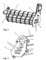
- the exhaust gas cooler of the embodiment according to Fig. 1 to Fig. 3 comprises a housing 1, which is traversed by a cooling liquid in the manner of a water jacket (coolant connections not shown).
- the cooling liquid may be connected to an engine cooling circuit or else to a separate low-temperature cooling circuit.
- each is a diesel engine for a motor vehicle, in particular a passenger car.
- the filter element 3 comprises a tube part 3a and a filter insert 3b defined therein by soldering or welding, which is approximately in the drawings 4 and FIG. 5 is shown schematically. Both the exchanger tubes 2 and the tube part 3 a of the filter element 3 are each fixed in the same perforated bottom part 4, for example by welding.
- the exhaust gas cooler is designed as a U-flow cooler and has an inlet side, according to Fig. 1 a connection member 5 with a feed 5a and a Outlet 5b is screwed for the exhaust gas on the inlet-side bottom part 4.
- a deflection region 6 is fixed on the bottom part there.
- the exhaust gas thus flows through the exhaust gas cooler first in an execution through the filter member, is then deflected in the deflection region 6 by 180 ° and flows through the exhaust gas cooler in the return direction through the exchanger tubes.
- the deflection region 6 is formed as a hollow chamber, into which also a bypass channel 7 opens.
- a bypass channel 7 opens.
- the exhaust gas cooler according to the present embodiments consists predominantly of corrosion-resistant steel. Depending on the exhaust gas temperature and design, at least some parts may also be made of aluminum or plastic (eg the water jacket 1).
- the exhaust gas cooler is integrated in an overall system in which the exhaust gas recirculation is designed as a low-pressure feedback.
- the exhaust gas cooler upstream of a regenerable Pumbleflter upstream and downstream of the air side of an exhaust gas turbocharger.
- the admixture of the exhaust gas to the combustion air of the engine takes place here before the compression by the turbocharger.
- the filter member 3 is formed as a non-regenerable permanent filter, which is designed for the entire life of the vehicle.
- a mesh size of the filter is designed so that only particles of a size that could endanger the turbocharger are filtered out.
- Fig. 5 corresponds to the example except for the arrangement of the exchanger tubes Fig. 4 ,
- Fig. 5 are the two end-face floor parts 4 and the cavity of the deflection 6 particularly clearly visible, for better clarity, only one of the exchanger tubes 3 is shown.
Landscapes
- Engineering & Computer Science (AREA)
- Mechanical Engineering (AREA)
- General Engineering & Computer Science (AREA)
- Chemical & Material Sciences (AREA)
- Combustion & Propulsion (AREA)
- Physics & Mathematics (AREA)
- Thermal Sciences (AREA)
- Chemical Kinetics & Catalysis (AREA)
- Exhaust-Gas Circulating Devices (AREA)
- Exhaust Gas After Treatment (AREA)
Description
- Die Erfindung betrifft einen Abgaskühler für einen Verbrennungsmotor nach dem Oberbegriff des Anspruchs 1, wie z.B. in
WO 2006/136372 beschrieben. - Es sind Systeme zur Abgas-Rückführung bekannt, bei denen das Abgas in einem Abgaskühler gekühlt und nachfolgend entweder stromabwärts eines Turboladers (Hochdruck-AGR) oder stromaufwärts eines Turboladers (Niederdruck-AGR) der Verbrennungsluft des Motors zugeführt wird. Abgas-Rückführsysteme werden vielfach zur Schadstoffreduzierung von Dieselmotoren eingesetzt, wobei zudem eine Partikelfilterung des Abgases vorgesehen ist. Ein solcher Partikelfilter ist regelmäßig als regenerativer Filter ausgelegt, wobei durch kontrolliert ausgelöste Abbrandphasen eine Reinigung des Filters erfolgt. Insbesondere in solchen Phasen aber auch allgemein konstruktionsbedingt können sich dabei größere Partikel lösen, die zum Beispiel im Fall der Niederdruck-AGR den Turbolader gefährden. Es ist daher bekannt, ein dem eigentlichen Partikelfilter nachgeordnetes und baulich getrenntes Filterglied vorzusehen, das nicht regenerativ ausgelegt ist, aber zumindest größere Partikel auf sichere Weise auffängt.
- Es ist die Aufgabe der Erfindung, einen Abgaskühler für einen Verbrennungsmotor anzugeben, durch den eine Integration von Komponenten ermöglicht ist.
- Diese Aufgabe wird für einen eingangs genannten Abgaskühler efindungsgemäß mit den kennzeichnenden Merkmalen des Anspruchs 1 gelöst. Durch die Integration des Filterglieds in den Abgaskühler kann eine zusätzliche, in den Abgasstrang zu integrierende Baugruppe eingespart werden. Bei dem kühlenden Fluid handelt es sich bevorzugt um ein flüssiges Kühlmittel, zum Beispiel eines Niedertemperatur-Kühlkreislaufs und/oder eines Kühlkreislaufs des Verbrennungsmotors.
- In bevorzugter Ausführungsform ist das Filterglied innerhalb des Gehäuses angeordnet, wobei insbesondere das Gehäuse von dem Fluid durchströmbar ist. Hierdurch wird wenig Bauraum benötigt. Insbesondere kann das Filterglied auf einfache Weise von dem Fluid umströmt werden und so zur Kühlung des Abgases beitragen.
- Bei der Erfindung wird der Abgaskühler von dem Abgas zumindest jeweils einmal in einer Hinrichtung und in einer Rückrichtung durchströmt, wobei das Filterglied in zumindest einem von beiden, Hinrichtung oder Rückrichtung, vorgesehen ist. Ein solcher Abgaskühler kann etwa als U-flow-Kühler oder auch als Z-flow-Kühler ausgebildet sein, wobei die Baugröße in einer Längsrichtung aufgrund der Umlenkung kompakt bleibt. In Anspruch 1 ist ein insbesondere einziger Strömungskanal der Hinrichtung als ein das Filterglied bildendes Rohrteil ausgebildet, wobei eine Mehrzahl von Strömungskanälen der Rückrichtung als Bündel von Tauscherrohren ausgebildet ist. Neben der einfachen und kompakten Bauweise hat dies den Vorteil, dass die Filterung durch das Filterglied stromaufwärts der Tauscherrohre erfolgt, so dass diese nicht durch größere Partikel blockiert werden können.
- Weiterhin vorteilhaft sind dabei im Interesse einer einfachen Herstellung das Rohrteil und/oder das Bündel von Tauscherrohren in endseitigen Bodenteilen aufgenommen. Insbesondere können dabei die gleichen Bodenteile jeweils sowohl das Filterglied als auch die Tauscherrohre halten.
- In weiterer Detailgestaltung ist dabei an einer Stirnseite des Abgaskühlers ein Umlenkbereich zur Umlenkung der Strömungsrichtung des Abgases ausgebildet.
- Das Filterglied kann einfach und kostengünstig als Rohrteil mit darin festgelegtem Filtereinsatz ausgebildet sein. Der Filtereinsatz kann zum Beispiel durch Schweißen oder Löten in dem Rohrteil festgelegt sein.
- Allgemein vorteilhaft ist für Betriebsarten wie zum Beispiel einer Kaltstartphase eine von Abgas durchströmbare Bypassleitung an dem Abgaskühler vorgesehen, wobei die Bypassleitung insbesondere stromabwärts des Filterglieds und stromaufwärts einer Mehrzahl der Strömungskanäle abzweigt. Hierdurch erfolgt jederzeit eine Filterung des Gasstroms, auch wenn das Abgas über die nicht oder nur wenig gekühlte Bypassleitung strömt.
- Allgemein bevorzugt ist das Filterglied als nicht im Betrieb regenerierbarer Dauerfilter ausgebildet. Je nach Anforderungen kann das Filterglied dabei auf die gesamte Lebensdauer des Verbrennungsmotors ausgelegt sein oder auch als austauschbares Bauteil bzw. Verschleißteil.
- In allgemein bevorzugter Ausführung ist der Abgaskühler zur Anordnung stromabwärts eines Partikelfilters ausgebildet. Dabei übernimmt der Partikelfilter die Aufgabe ein regenerierbaren Feinstaubfilters und das Filterglied hat vorrangig die Aufgabe eines Schutzfilters für größere Partikel, die zum Beispiel in einer Abbrandphase des Partikelfilters entstehen und einen nachfolgenden Turbolader gefährden können. Allgemein vorteilhaft ist ein erfindungsgemäßer Abgaskühler daher aus gleichem Grund zur Anordnung stromaufwärts eines Turboladers (Niederdruck-Abgasrückführung) ausgebildet.
- Weitere Vorteile und Merkmale der Erfindung ergeben sich aus den nachfolgenden Ausführungsbeispielen sowie den abhängigen Ansprüchen.
- Nachfolgend werden mehrere bevorzugte Ausführungsbeispiele eines Abgaskühlers beschrieben und anhand der anliegenden Zeichnungen näher erläutert.
- Fig. 1
- zeigt eine räumliche Darstellung eines erfindungsgemäßen Ab- gaskühlers.
- Fig. 2
- zeigt eine räumliche Ansicht des Abgaskühlers aus
Fig. 1 ohne Anschlussbereich. - Fig. 3
- zeigt eine Ausschnittvergrößerung des Abgaskühlers aus
Fig. 2 - Fig. 4
- zeigt eine weitere Ausführungsform eines erfindungsgemäßen Abgaskühlers in räumlicher, aufgeschnittener Darstellung.
- Fig. 5
- zeigt eine Abwandlung des Abgaskühlers aus
Fig. 4 . - Der Abgaskühler der Ausführungsform nach
Fig. 1 bis Fig. 3 umfasst ein Gehäuse 1, das nach Art eines Wassermantels von einer Kühlflüssigkeit durchströmbar ist (Kühlmittelanschlüsse nicht dargestellt). Die Kühlflüssigkeit kann etwa an einen Motorkühlkreislauf angeschlossen sein oder auch an einen separaten Niedertemperatur-Kühlkreislauf. - In dem Gehäuse 1 sind ein Bündel aus Tauscherrohren 2 sowie ein rohrförmiges Filterglied 3 parallel zueinander angeordnet, die jeweils Strömungskanäle für Abgas eines Verbrennungsmotors ausbilden. In den vorliegenden Beispielen handelt es sich jeweils um einen Dieselmotor für ein Kraftfahrzeug, insbesondere einen Personenkraftwagen.
- Das Filterglied 3 umfasst ein Rohrteil 3a sowie einen darin durch Verlötung oder Verschweißung festgelegten Filtereinsatz 3b, welcher etwa in den Zeichnungen
Fig. 4 und Fig. 5 schematisch dargestellt ist. Sowohl die Tauscherrohre 2 als auch das Rohrteil 3a des Filterglieds 3 sind endseitig jeweils in demselben durchbrochenen Bodenteil 4 festgelegt, etwa durch Verschweißung. - Der Abgaskühler ist als U-Flow-Kühler ausgelegt und hat eine Eintrittsseite, auf der gemäß
Fig. 1 ein Anschlussglied 5 mit einer Zuführung 5a und einer Abführung 5b für das Abgas auf dem eintrittsseitigen Bodenteil 4 aufgeschraubt ist. - An dem gegenüberliegenden Ende der Strömungskanäle ist ein Umlenkbereich 6 auf dem dortigen Bodenteil festgelegt. Das Abgas durchströmt den Abgaskühler somit zunächst in einer Hinrichtung durch das Filterglied, wird dann in dem Umlenkbereich 6 um 180° umgelenkt und durchströmt den Abgaskühler in der Rückrichtung durch die Tauscherrohre 2.
- Der Umlenkbereich 6 ist als hohle Kammer ausgebildet, in die zudem ein Bypasskanal 7 mündet. Hierdurch kann zum Beispiel in einer Kaltstartphase der Abgasstrom zunächst das Filterglied 3 durchströmen und dann ohne weitere Kühlung durch den Bypasskanal 7 abgeführt werden. Der überwiegende Teil der Abgaskühlung erfolgt durch das Bündel von Tauscherrohren 2, wobei eine geringe Wärmeabführung auch durch das kühlmittelumströmte Filterglied 3 gegeben ist.
- Der Abgaskühler gemäß den vorliegenden Ausführungsbeispielen besteht überwiegend aus korrosionsresistentem Stahl. Je nach Abgastemperatur und Auslegung können zumindest einige Teile auch aus Aluminium oder Kunststoff (z. B. der Wassermantel 1) bestehen.
- Der Abgaskühler ist in ein Gesamtsystem eingebunden, bei dem die Abgasrückführung als Niederdruck-Rückführung ausgelegt ist. In Strömungsrichtung ist dem Abgaskühler ein regenerierbarer Partikelflter vorgeordnet und die Luftseite eines Abgas-Turboladers nachgeordnet. Die Beimischung des Abgases zu der Verbrennungsluft des Motors erfolgt hier also vor der Verdichtung durch den Turbolader.
- Das Filterglied 3 ist als nicht regenerierbarer Dauerfilter ausgebildet, der für die gesamte Lebensdauer des Fahrzeugs ausgelegt ist. Eine Maschenweite des Filters ist entsprechend so gestaltet, dass nur Partikel einer Größe, die den Turbolader gefährden könnten, ausgefiltert werden.
- Bei dem Ausführungsbeispiel nach
Fig. 4 sind zur weiteren Veranschaulichung die Richtungen des Abgasstroms durch Pfeile angedeutet. Neben einer anderen Anordnung der Tauscherrohre besteht der Unterschied zu dem ersten Ausführungsbeispiel darin, dass kein Bypasskanal vorgesehen ist. - Die Abwandlung nach
Fig. 5 entspricht bis auf die Anordnung der Tauscherrohre dem Beispiel ausFig. 4 . InFig. 5 sind die beiden stimseitigen Bodenteile 4 und der Hohlraum des Umlenkbereichs 6 besonders gut erkennbar, wobei zur besseren Übersicht nur eines der Tauscherrohre 3 dargestellt ist.
Claims (9)
- Abgaskühler für einen Verbrennungsmotor, umfassend eine Mehrzahl von Abgas führenden Strömungskanälen (2, 3), wobei die Strömungskanäle (2, 3) innerhalb eines Gehäuses (1) angeordnet sind und mit einem Fluid zur Kühlung des Abgases in thermischem Austausch stehen, wobei
zumindest ein Filterglied (3) zur Filterung von Partikeln aus dem Abgasstrom baulich in den Abgaskühler integriert ist, dadurch gekennzeichnet, dass der Abgaskühler von dem Abgas zumindest jeweils einmal in einer Hinrichtung und in einer Rückrichtung durchströmbar ist, wobei das Filterglied (3) in zumindest einer von beiden, Hinrichtung oder Rückrichtung, vorgesehen ist und ein insbesondere einziger Strömungskanal der Hinrichtung als ein das Filterglied (3) bildendes Rohrteil (3a) ausgebildet ist, wobei eine mehrzahl von Strömungskanälen der Rückrichtung als Bündel von Tauscherrohren (2) ausgebildet ist. - Abgasktihler nach Anspruch 1, dadurch gekennzeichnet, dass das Filterglied (3) innerhalb des Gehäuses (1) angeordnet ist, wobei insbesondere das Gehäuse (1) von dem Fluid durchströmbar ist.
- Abgaskühler nach Anspruch 1 oder 2 dadurch gekennzeichnet, dass das Rohrteil (3a) und/oder das Bündel von Tauscherrohren (2) in endseitigen Bodenteilen (4) aufgenommen sind.
- Abgaskühler nach einem der Ansprüche 1 bis 3, dadurch gekennzeichnet, dass an einer Stirnseite des Abgaskühlers ein Umlenkbereich (6) zur Umlenkung der Strömungsrichtung des Abgases ausgebildet ist.
- Abgaskühler nach einem der vorhergehenden Ansprüche, dadurch gekennzeichnet, dass das Filterglied (3) als Rohrteil (3a) mit darin festgelegtem Filtereinsatz (3b) ausgebildet ist.
- Abgaskühler nach einem der vorhergehenden Ansprüche, dadurch gekennzeichnet, dass eine von Abgas durchströmbare Bypassleitung (7) vorgesehen ist, wobei die Bypassleitung (7) insbesondere stromabwärts des Filterglieds (3) und stromaufwärts einer Mehrzahl der Strömungskanäle (2) abzweigt.
- Abgaskühler nach einem der vorhergehenden Ansprüche, dadurch gekennzeichnet, dass das Filterglied (3) als nicht im Betrieb regenerierbarer Dauerfilter ausgebildet ist.
- Abgaskühler nach einem der vorhergehenden Ansprüche, dadurch gekennzeichnet, dass der Abgaskühler zur Anordnung stromabwärts eines Partikelfilters ausgebildet ist.
- Abgaskühler nach einem der vorhergehenden Ansprüche, dadurch gekennzeichnet, dass der Abgaskühler zur Anordnung stromaufwärts eines Turboladers ausgebildet ist.
Priority Applications (3)
| Application Number | Priority Date | Filing Date | Title |
|---|---|---|---|
| EP08291142A EP2194351B1 (de) | 2008-12-03 | 2008-12-03 | Abgaskühler mit integrierten Partikelfilter für einen Verbrennungsmotor |
| AT08291142T ATE556284T1 (de) | 2008-12-03 | 2008-12-03 | Abgaskühler mit integrierten partikelfilter für einen verbrennungsmotor |
| US12/591,669 US20100132346A1 (en) | 2008-12-03 | 2009-11-27 | Exhaust-gas cooler for an internal combustion engine |
Applications Claiming Priority (1)
| Application Number | Priority Date | Filing Date | Title |
|---|---|---|---|
| EP08291142A EP2194351B1 (de) | 2008-12-03 | 2008-12-03 | Abgaskühler mit integrierten Partikelfilter für einen Verbrennungsmotor |
Publications (2)
| Publication Number | Publication Date |
|---|---|
| EP2194351A1 EP2194351A1 (de) | 2010-06-09 |
| EP2194351B1 true EP2194351B1 (de) | 2012-05-02 |
Family
ID=40602246
Family Applications (1)
| Application Number | Title | Priority Date | Filing Date |
|---|---|---|---|
| EP08291142A Not-in-force EP2194351B1 (de) | 2008-12-03 | 2008-12-03 | Abgaskühler mit integrierten Partikelfilter für einen Verbrennungsmotor |
Country Status (3)
| Country | Link |
|---|---|
| US (1) | US20100132346A1 (de) |
| EP (1) | EP2194351B1 (de) |
| AT (1) | ATE556284T1 (de) |
Cited By (8)
| Publication number | Priority date | Publication date | Assignee | Title |
|---|---|---|---|---|
| EP2801709A1 (de) | 2013-05-08 | 2014-11-12 | MAHLE Behr GmbH & Co. KG | Abgaskühler |
| DE102015108224A1 (de) | 2014-12-17 | 2016-06-23 | Tenneco Gmbh | AGR-System mit Partikelfilter für Ottomotor |
| DE102014118813A1 (de) | 2014-12-17 | 2016-06-23 | Tenneco Gmbh | AGR-System mit Partikelfilter für Ottomotor |
| DE102015108223A1 (de) | 2015-05-26 | 2016-12-01 | Tenneco Gmbh | AGR-System mit Partikelfilter und Wastegate |
| WO2016189028A1 (de) | 2015-05-26 | 2016-12-01 | Tenneco Gmbh | Agr-system mit partikelfilter und wastegate |
| WO2017108615A1 (fr) | 2015-12-21 | 2017-06-29 | Valeo Termico, S.A. | Ensemble unité de conduite de gaz avec filtre à particules, procédé de fabrication de celui-ci et échangeur thermique pour gaz, en particulier pour les gaz d'échappement d'un moteur |
| US10415513B2 (en) | 2015-05-26 | 2019-09-17 | Tenneco Gmbh | EGR system with particle filter and wastegate |
| US10480460B2 (en) | 2014-12-17 | 2019-11-19 | Tenneco Gmbh | EGR system with particle filter for a gasoline engine |
Families Citing this family (15)
| Publication number | Priority date | Publication date | Assignee | Title |
|---|---|---|---|---|
| DE202009001782U1 (de) * | 2009-02-12 | 2010-07-08 | Mann+Hummel Gmbh | Abgasansaugvorrichtung |
| EP2273095B1 (de) * | 2009-07-10 | 2014-01-08 | Behr GmbH & Co. KG | Wärmetauscher, Abgasrückführsystem und Brennkraftmaschine |
| EP2463490B1 (de) * | 2010-12-10 | 2015-09-09 | Perkins Engines Company Limited | Verbesserungen an oder in Zusammenhang mit Gaskühlern für Verbrennungsmotoren |
| DE102011001461B4 (de) | 2011-03-22 | 2017-01-26 | Pierburg Gmbh | Abgasrückführmodul für eine Verbrennungskraftmaschine |
| ES2421185B1 (es) | 2012-02-22 | 2014-08-11 | Valeo Térmico, S. A. | Intercambiador de calor para gases, en especial de los gases de escape de un motor |
| WO2013184135A1 (en) * | 2012-06-08 | 2013-12-12 | International Engine Intellectual Property Company, Llc | Egr cooler header casting |
| CN102900570B (zh) * | 2012-09-20 | 2014-11-12 | 浙江银轮机械股份有限公司 | 一种u型egr冷却器 |
| EP2781730A1 (de) | 2013-03-19 | 2014-09-24 | Borgwarner Inc. | Kompakte Vorrichtung zur Abgasverwaltung in einem AGR-System |
| DE102013211221A1 (de) * | 2013-06-14 | 2014-12-18 | Behr Gmbh & Co. Kg | Wärmeübertrager |
| ES2531124B1 (es) | 2013-09-10 | 2016-01-22 | Valeo Térmico, S. A. | Intercambiador de calor para gases, en especial de los gases de escape de un motor |
| US20160215735A1 (en) * | 2013-09-11 | 2016-07-28 | International Engine Intellectual Property Company, Llc | Thermal screen for an egr cooler |
| DE102015217541B4 (de) * | 2015-09-14 | 2017-04-06 | Magna powertrain gmbh & co kg | Kühleranordnung für ein Kraftfahrzeug |
| DE102016109247B4 (de) * | 2016-05-19 | 2020-03-26 | Benteler Automobiltechnik Gmbh | Abgaswärmeübertrager |
| US10215135B2 (en) * | 2016-07-22 | 2019-02-26 | Ford Global Technologies, Llc | System and methods for extracting water from exhaust gases for water injection |
| JP2021055856A (ja) * | 2019-09-27 | 2021-04-08 | 株式会社ユタカ技研 | 熱交換器 |
Family Cites Families (4)
| Publication number | Priority date | Publication date | Assignee | Title |
|---|---|---|---|---|
| DE102005029322A1 (de) * | 2005-06-24 | 2006-12-28 | Behr Gmbh & Co. Kg | Vorrichtung zur Rückführung und Kühlung von Abgas für eine Brennkraftmaschine |
| DE102006038706B4 (de) * | 2006-08-18 | 2018-12-27 | Volkswagen Ag | Brennkraftmaschine mit Niederdruck-Abgasrückführung |
| WO2008058734A1 (de) * | 2006-11-15 | 2008-05-22 | Behr Gmbh & Co. Kg | Wärmeübertrager für kraftfahrzeug mit stranggepresstem gekrümmten strömungskanal |
| DE102007025704A1 (de) * | 2007-06-01 | 2008-12-04 | Volkswagen Ag | Brennkraftmaschine mit ND-EGR-Leitung |
-
2008
- 2008-12-03 EP EP08291142A patent/EP2194351B1/de not_active Not-in-force
- 2008-12-03 AT AT08291142T patent/ATE556284T1/de active
-
2009
- 2009-11-27 US US12/591,669 patent/US20100132346A1/en not_active Abandoned
Cited By (14)
| Publication number | Priority date | Publication date | Assignee | Title |
|---|---|---|---|---|
| DE102013208436A1 (de) | 2013-05-08 | 2014-11-13 | MAHLE Behr GmbH & Co. KG | Abgaskühler |
| EP2801709A1 (de) | 2013-05-08 | 2014-11-12 | MAHLE Behr GmbH & Co. KG | Abgaskühler |
| US10458368B2 (en) | 2014-12-17 | 2019-10-29 | Tenneco Gmbh | EGR system with particle filter for a gasoline engine |
| DE102015108224A1 (de) | 2014-12-17 | 2016-06-23 | Tenneco Gmbh | AGR-System mit Partikelfilter für Ottomotor |
| DE102014118813A1 (de) | 2014-12-17 | 2016-06-23 | Tenneco Gmbh | AGR-System mit Partikelfilter für Ottomotor |
| WO2016097197A1 (de) | 2014-12-17 | 2016-06-23 | Tenneco Gmbh | Agr-system mit partikelfilter für ottomotor |
| DE102015108224B4 (de) | 2014-12-17 | 2026-03-05 | Tenneco Gmbh | AGR-System mit Partikelfilter für Ottomotor |
| US10480460B2 (en) | 2014-12-17 | 2019-11-19 | Tenneco Gmbh | EGR system with particle filter for a gasoline engine |
| WO2016189028A1 (de) | 2015-05-26 | 2016-12-01 | Tenneco Gmbh | Agr-system mit partikelfilter und wastegate |
| US10415513B2 (en) | 2015-05-26 | 2019-09-17 | Tenneco Gmbh | EGR system with particle filter and wastegate |
| DE102015108223B4 (de) | 2015-05-26 | 2018-04-19 | Tenneco Gmbh | AGR-System mit Partikelfilter und Wastegate |
| US10502166B2 (en) | 2015-05-26 | 2019-12-10 | Tenneco Gmbh | EGR system with particle filter and wastegate |
| DE102015108223A1 (de) | 2015-05-26 | 2016-12-01 | Tenneco Gmbh | AGR-System mit Partikelfilter und Wastegate |
| WO2017108615A1 (fr) | 2015-12-21 | 2017-06-29 | Valeo Termico, S.A. | Ensemble unité de conduite de gaz avec filtre à particules, procédé de fabrication de celui-ci et échangeur thermique pour gaz, en particulier pour les gaz d'échappement d'un moteur |
Also Published As
| Publication number | Publication date |
|---|---|
| EP2194351A1 (de) | 2010-06-09 |
| US20100132346A1 (en) | 2010-06-03 |
| ATE556284T1 (de) | 2012-05-15 |
Similar Documents
| Publication | Publication Date | Title |
|---|---|---|
| EP2194351A1 (de) | Abgaskühler mit integrierten Partikelfilter für einen Verbrennungsmotor | |
| EP2667007B1 (de) | Wärmetauscher, Abgasrückführsystem und Brennkraftmaschine | |
| EP2020501B1 (de) | Wärmetauschergehäuse, Wärmetauscher oder Baueinheit mit einem oder mehreren Wärmetauschern, Abgasrückführsystem, Ladeluftzuführsystem und Verwendung des Wärmetauschers | |
| WO2007104491A1 (de) | Wärmetauscher für ein kraftfahrzeug | |
| DE102013205267A1 (de) | Luft-Flüssigkeits-Wärmetauscher | |
| DE102005014385A1 (de) | Abgaswärmeübertrager, insbesondere Abgaskühler für Abgasrückführung in Kraftfahrzeugen | |
| WO2008101978A1 (de) | Frischgasmodul für eine frischgasanlage | |
| EP1857761A2 (de) | Wärmeübertragungseinheit für Verbrennungskraftmaschinen | |
| DE102006033314A1 (de) | Wärmetauschersystem und Verfahren zum Betreiben eines derartigen Wärmetauschersystems | |
| DE112004000310B3 (de) | Motorbremsanlage einer Mehrzylinderbrennkraftmaschine mit gekühltem Zwischenrohr für Gaswechsel zwischen Zylindern beim Motorbremsen | |
| DE102015009501A1 (de) | Brennkraftmaschinenkühlung | |
| EP2212540B1 (de) | Vorrichtung und verfahren zur rückführung von abgas eines verbrennungsmotors | |
| EP2699785B1 (de) | Abgaskühler zum kühlen von verbrennungsabgas einer verbrennungskraftmaschine, abgaskühlsystem und verfahren zum herstellen eines abgaskühlsystems | |
| WO2019072853A1 (de) | Abgaswärmeübertrager | |
| EP2324227B1 (de) | Abgaskühlung für ein kraftfahrzeug | |
| DE102010033718B4 (de) | Kraftwagen mit einer Verbrennungskraftmaschine | |
| DE102008062145A1 (de) | Motor mit Turbo-Superlader | |
| WO2008058737A1 (de) | Abgasrückführeinrichtung | |
| DE102020201350B4 (de) | Baugruppe für ein Kühlsystem eines Kraftfahrzeugs mit einem Wärmetauscher, einem Steuerventil und einer Stellvorrichtung | |
| DE102012206974A1 (de) | Abgasrückführungsanlage | |
| DE102005036045B4 (de) | Kühlvorrichtung für Verbrennungskraftmaschinen | |
| EP1975400B1 (de) | Kühlvorrichtung für rückgeführtes Abgas | |
| DE102008005275B4 (de) | Verfahren und Vorrichtung zum Betreiben eines Wärmetauschersystems für ein Kraftfahrzeug | |
| DE102014201937A1 (de) | Ladeluftkühler | |
| DE102016205752A1 (de) | Abgas-Rückführ-Kühler |
Legal Events
| Date | Code | Title | Description |
|---|---|---|---|
| PUAI | Public reference made under article 153(3) epc to a published international application that has entered the european phase |
Free format text: ORIGINAL CODE: 0009012 |
|
| AK | Designated contracting states |
Kind code of ref document: A1 Designated state(s): AT BE BG CH CY CZ DE DK EE ES FI FR GB GR HR HU IE IS IT LI LT LU LV MC MT NL NO PL PT RO SE SI SK TR |
|
| AX | Request for extension of the european patent |
Extension state: AL BA MK RS |
|
| 17P | Request for examination filed |
Effective date: 20101209 |
|
| AKX | Designation fees paid |
Designated state(s): AT BE BG CH CY CZ DE DK EE ES FI FR GB GR HR HU IE IS IT LI LT LU LV MC MT NL NO PL PT RO SE SI SK TR |
|
| 17Q | First examination report despatched |
Effective date: 20110124 |
|
| GRAP | Despatch of communication of intention to grant a patent |
Free format text: ORIGINAL CODE: EPIDOSNIGR1 |
|
| GRAS | Grant fee paid |
Free format text: ORIGINAL CODE: EPIDOSNIGR3 |
|
| GRAA | (expected) grant |
Free format text: ORIGINAL CODE: 0009210 |
|
| AK | Designated contracting states |
Kind code of ref document: B1 Designated state(s): AT BE BG CH CY CZ DE DK EE ES FI FR GB GR HR HU IE IS IT LI LT LU LV MC MT NL NO PL PT RO SE SI SK TR |
|
| REG | Reference to a national code |
Ref country code: GB Ref legal event code: FG4D Free format text: NOT ENGLISH |
|
| REG | Reference to a national code |
Ref country code: AT Ref legal event code: REF Ref document number: 556284 Country of ref document: AT Kind code of ref document: T Effective date: 20120515 Ref country code: CH Ref legal event code: EP |
|
| REG | Reference to a national code |
Ref country code: IE Ref legal event code: FG4D Free format text: LANGUAGE OF EP DOCUMENT: GERMAN |
|
| REG | Reference to a national code |
Ref country code: DE Ref legal event code: R096 Ref document number: 502008007118 Country of ref document: DE Effective date: 20120628 |
|
| REG | Reference to a national code |
Ref country code: NL Ref legal event code: VDEP Effective date: 20120502 |
|
| REG | Reference to a national code |
Ref country code: LT Ref legal event code: MG4D Effective date: 20120502 |
|
| PG25 | Lapsed in a contracting state [announced via postgrant information from national office to epo] |
Ref country code: IS Free format text: LAPSE BECAUSE OF FAILURE TO SUBMIT A TRANSLATION OF THE DESCRIPTION OR TO PAY THE FEE WITHIN THE PRESCRIBED TIME-LIMIT Effective date: 20120902 Ref country code: NO Free format text: LAPSE BECAUSE OF FAILURE TO SUBMIT A TRANSLATION OF THE DESCRIPTION OR TO PAY THE FEE WITHIN THE PRESCRIBED TIME-LIMIT Effective date: 20120802 Ref country code: CY Free format text: LAPSE BECAUSE OF FAILURE TO SUBMIT A TRANSLATION OF THE DESCRIPTION OR TO PAY THE FEE WITHIN THE PRESCRIBED TIME-LIMIT Effective date: 20120502 Ref country code: SE Free format text: LAPSE BECAUSE OF FAILURE TO SUBMIT A TRANSLATION OF THE DESCRIPTION OR TO PAY THE FEE WITHIN THE PRESCRIBED TIME-LIMIT Effective date: 20120502 Ref country code: PL Free format text: LAPSE BECAUSE OF FAILURE TO SUBMIT A TRANSLATION OF THE DESCRIPTION OR TO PAY THE FEE WITHIN THE PRESCRIBED TIME-LIMIT Effective date: 20120502 Ref country code: FI Free format text: LAPSE BECAUSE OF FAILURE TO SUBMIT A TRANSLATION OF THE DESCRIPTION OR TO PAY THE FEE WITHIN THE PRESCRIBED TIME-LIMIT Effective date: 20120502 Ref country code: LT Free format text: LAPSE BECAUSE OF FAILURE TO SUBMIT A TRANSLATION OF THE DESCRIPTION OR TO PAY THE FEE WITHIN THE PRESCRIBED TIME-LIMIT Effective date: 20120502 |
|
| PG25 | Lapsed in a contracting state [announced via postgrant information from national office to epo] |
Ref country code: GR Free format text: LAPSE BECAUSE OF FAILURE TO SUBMIT A TRANSLATION OF THE DESCRIPTION OR TO PAY THE FEE WITHIN THE PRESCRIBED TIME-LIMIT Effective date: 20120803 Ref country code: SI Free format text: LAPSE BECAUSE OF FAILURE TO SUBMIT A TRANSLATION OF THE DESCRIPTION OR TO PAY THE FEE WITHIN THE PRESCRIBED TIME-LIMIT Effective date: 20120502 Ref country code: LV Free format text: LAPSE BECAUSE OF FAILURE TO SUBMIT A TRANSLATION OF THE DESCRIPTION OR TO PAY THE FEE WITHIN THE PRESCRIBED TIME-LIMIT Effective date: 20120502 Ref country code: PT Free format text: LAPSE BECAUSE OF FAILURE TO SUBMIT A TRANSLATION OF THE DESCRIPTION OR TO PAY THE FEE WITHIN THE PRESCRIBED TIME-LIMIT Effective date: 20120903 Ref country code: HR Free format text: LAPSE BECAUSE OF FAILURE TO SUBMIT A TRANSLATION OF THE DESCRIPTION OR TO PAY THE FEE WITHIN THE PRESCRIBED TIME-LIMIT Effective date: 20120502 |
|
| PG25 | Lapsed in a contracting state [announced via postgrant information from national office to epo] |
Ref country code: DK Free format text: LAPSE BECAUSE OF FAILURE TO SUBMIT A TRANSLATION OF THE DESCRIPTION OR TO PAY THE FEE WITHIN THE PRESCRIBED TIME-LIMIT Effective date: 20120502 Ref country code: NL Free format text: LAPSE BECAUSE OF FAILURE TO SUBMIT A TRANSLATION OF THE DESCRIPTION OR TO PAY THE FEE WITHIN THE PRESCRIBED TIME-LIMIT Effective date: 20120502 Ref country code: RO Free format text: LAPSE BECAUSE OF FAILURE TO SUBMIT A TRANSLATION OF THE DESCRIPTION OR TO PAY THE FEE WITHIN THE PRESCRIBED TIME-LIMIT Effective date: 20120502 Ref country code: CZ Free format text: LAPSE BECAUSE OF FAILURE TO SUBMIT A TRANSLATION OF THE DESCRIPTION OR TO PAY THE FEE WITHIN THE PRESCRIBED TIME-LIMIT Effective date: 20120502 Ref country code: EE Free format text: LAPSE BECAUSE OF FAILURE TO SUBMIT A TRANSLATION OF THE DESCRIPTION OR TO PAY THE FEE WITHIN THE PRESCRIBED TIME-LIMIT Effective date: 20120502 Ref country code: SK Free format text: LAPSE BECAUSE OF FAILURE TO SUBMIT A TRANSLATION OF THE DESCRIPTION OR TO PAY THE FEE WITHIN THE PRESCRIBED TIME-LIMIT Effective date: 20120502 |
|
| PG25 | Lapsed in a contracting state [announced via postgrant information from national office to epo] |
Ref country code: IT Free format text: LAPSE BECAUSE OF FAILURE TO SUBMIT A TRANSLATION OF THE DESCRIPTION OR TO PAY THE FEE WITHIN THE PRESCRIBED TIME-LIMIT Effective date: 20120502 |
|
| PLBE | No opposition filed within time limit |
Free format text: ORIGINAL CODE: 0009261 |
|
| STAA | Information on the status of an ep patent application or granted ep patent |
Free format text: STATUS: NO OPPOSITION FILED WITHIN TIME LIMIT |
|
| 26N | No opposition filed |
Effective date: 20130205 |
|
| PG25 | Lapsed in a contracting state [announced via postgrant information from national office to epo] |
Ref country code: ES Free format text: LAPSE BECAUSE OF FAILURE TO SUBMIT A TRANSLATION OF THE DESCRIPTION OR TO PAY THE FEE WITHIN THE PRESCRIBED TIME-LIMIT Effective date: 20120813 |
|
| REG | Reference to a national code |
Ref country code: DE Ref legal event code: R097 Ref document number: 502008007118 Country of ref document: DE Effective date: 20130205 |
|
| BERE | Be: lapsed |
Owner name: BEHR G.M.B.H. & CO. KG Effective date: 20121231 Owner name: BEHR FRANCE ROUFFACH SAS Effective date: 20121231 |
|
| PG25 | Lapsed in a contracting state [announced via postgrant information from national office to epo] |
Ref country code: MC Free format text: LAPSE BECAUSE OF NON-PAYMENT OF DUE FEES Effective date: 20121231 Ref country code: BG Free format text: LAPSE BECAUSE OF FAILURE TO SUBMIT A TRANSLATION OF THE DESCRIPTION OR TO PAY THE FEE WITHIN THE PRESCRIBED TIME-LIMIT Effective date: 20120802 |
|
| REG | Reference to a national code |
Ref country code: CH Ref legal event code: PL |
|
| REG | Reference to a national code |
Ref country code: IE Ref legal event code: MM4A |
|
| PG25 | Lapsed in a contracting state [announced via postgrant information from national office to epo] |
Ref country code: BE Free format text: LAPSE BECAUSE OF NON-PAYMENT OF DUE FEES Effective date: 20121231 |
|
| PG25 | Lapsed in a contracting state [announced via postgrant information from national office to epo] |
Ref country code: CH Free format text: LAPSE BECAUSE OF NON-PAYMENT OF DUE FEES Effective date: 20121231 Ref country code: LI Free format text: LAPSE BECAUSE OF NON-PAYMENT OF DUE FEES Effective date: 20121231 Ref country code: IE Free format text: LAPSE BECAUSE OF NON-PAYMENT OF DUE FEES Effective date: 20121203 |
|
| PG25 | Lapsed in a contracting state [announced via postgrant information from national office to epo] |
Ref country code: MT Free format text: LAPSE BECAUSE OF FAILURE TO SUBMIT A TRANSLATION OF THE DESCRIPTION OR TO PAY THE FEE WITHIN THE PRESCRIBED TIME-LIMIT Effective date: 20120502 |
|
| PG25 | Lapsed in a contracting state [announced via postgrant information from national office to epo] |
Ref country code: TR Free format text: LAPSE BECAUSE OF FAILURE TO SUBMIT A TRANSLATION OF THE DESCRIPTION OR TO PAY THE FEE WITHIN THE PRESCRIBED TIME-LIMIT Effective date: 20120502 |
|
| PG25 | Lapsed in a contracting state [announced via postgrant information from national office to epo] |
Ref country code: LU Free format text: LAPSE BECAUSE OF NON-PAYMENT OF DUE FEES Effective date: 20121203 |
|
| PG25 | Lapsed in a contracting state [announced via postgrant information from national office to epo] |
Ref country code: HU Free format text: LAPSE BECAUSE OF FAILURE TO SUBMIT A TRANSLATION OF THE DESCRIPTION OR TO PAY THE FEE WITHIN THE PRESCRIBED TIME-LIMIT Effective date: 20081203 |
|
| REG | Reference to a national code |
Ref country code: AT Ref legal event code: MM01 Ref document number: 556284 Country of ref document: AT Kind code of ref document: T Effective date: 20131203 |
|
| PG25 | Lapsed in a contracting state [announced via postgrant information from national office to epo] |
Ref country code: AT Free format text: LAPSE BECAUSE OF NON-PAYMENT OF DUE FEES Effective date: 20131203 |
|
| REG | Reference to a national code |
Ref country code: DE Ref legal event code: R082 Ref document number: 502008007118 Country of ref document: DE Representative=s name: GRAUEL, ANDREAS, DIPL.-PHYS. DR. RER. NAT., DE Ref country code: DE Ref legal event code: R081 Ref document number: 502008007118 Country of ref document: DE Owner name: MAHLE INTERNATIONAL GMBH, DE Free format text: FORMER OWNERS: BEHR GMBH & CO. KG, 70469 STUTTGART, DE; BEHR FRANCE ROUFFACH S.A.S., ROUFFACH, FR |
|
| REG | Reference to a national code |
Ref country code: FR Ref legal event code: PLFP Year of fee payment: 8 |
|
| REG | Reference to a national code |
Ref country code: FR Ref legal event code: PLFP Year of fee payment: 9 |
|
| REG | Reference to a national code |
Ref country code: FR Ref legal event code: PLFP Year of fee payment: 10 |
|
| PGFP | Annual fee paid to national office [announced via postgrant information from national office to epo] |
Ref country code: FR Payment date: 20191220 Year of fee payment: 12 |
|
| PGFP | Annual fee paid to national office [announced via postgrant information from national office to epo] |
Ref country code: GB Payment date: 20191220 Year of fee payment: 12 Ref country code: DE Payment date: 20200220 Year of fee payment: 12 |
|
| REG | Reference to a national code |
Ref country code: DE Ref legal event code: R119 Ref document number: 502008007118 Country of ref document: DE |
|
| GBPC | Gb: european patent ceased through non-payment of renewal fee |
Effective date: 20201203 |
|
| PG25 | Lapsed in a contracting state [announced via postgrant information from national office to epo] |
Ref country code: FR Free format text: LAPSE BECAUSE OF NON-PAYMENT OF DUE FEES Effective date: 20201231 |
|
| PG25 | Lapsed in a contracting state [announced via postgrant information from national office to epo] |
Ref country code: GB Free format text: LAPSE BECAUSE OF NON-PAYMENT OF DUE FEES Effective date: 20201203 Ref country code: DE Free format text: LAPSE BECAUSE OF NON-PAYMENT OF DUE FEES Effective date: 20210701 |