EP2194351B1 - Refroidisseur de gaz d'échappement avec un filtre intégré pour un moteur à combustion - Google Patents
Refroidisseur de gaz d'échappement avec un filtre intégré pour un moteur à combustion Download PDFInfo
- Publication number
- EP2194351B1 EP2194351B1 EP08291142A EP08291142A EP2194351B1 EP 2194351 B1 EP2194351 B1 EP 2194351B1 EP 08291142 A EP08291142 A EP 08291142A EP 08291142 A EP08291142 A EP 08291142A EP 2194351 B1 EP2194351 B1 EP 2194351B1
- Authority
- EP
- European Patent Office
- Prior art keywords
- exhaust gas
- gas cooler
- flow
- designed
- filter element
- Prior art date
- Legal status (The legal status is an assumption and is not a legal conclusion. Google has not performed a legal analysis and makes no representation as to the accuracy of the status listed.)
- Not-in-force
Links
Images


Classifications
-
- F—MECHANICAL ENGINEERING; LIGHTING; HEATING; WEAPONS; BLASTING
- F28—HEAT EXCHANGE IN GENERAL
- F28D—HEAT-EXCHANGE APPARATUS, NOT PROVIDED FOR IN ANOTHER SUBCLASS, IN WHICH THE HEAT-EXCHANGE MEDIA DO NOT COME INTO DIRECT CONTACT
- F28D7/00—Heat-exchange apparatus having stationary tubular conduit assemblies for both heat-exchange media, the media being in contact with different sides of a conduit wall
- F28D7/16—Heat-exchange apparatus having stationary tubular conduit assemblies for both heat-exchange media, the media being in contact with different sides of a conduit wall the conduits being arranged in parallel spaced relation
- F28D7/1684—Heat-exchange apparatus having stationary tubular conduit assemblies for both heat-exchange media, the media being in contact with different sides of a conduit wall the conduits being arranged in parallel spaced relation the conduits having a non-circular cross-section
-
- F—MECHANICAL ENGINEERING; LIGHTING; HEATING; WEAPONS; BLASTING
- F02—COMBUSTION ENGINES; HOT-GAS OR COMBUSTION-PRODUCT ENGINE PLANTS
- F02M—SUPPLYING COMBUSTION ENGINES IN GENERAL WITH COMBUSTIBLE MIXTURES OR CONSTITUENTS THEREOF
- F02M26/00—Engine-pertinent apparatus for adding exhaust gases to combustion-air, main fuel or fuel-air mixture, e.g. by exhaust gas recirculation [EGR] systems
- F02M26/13—Arrangement or layout of EGR passages, e.g. in relation to specific engine parts or for incorporation of accessories
- F02M26/22—Arrangement or layout of EGR passages, e.g. in relation to specific engine parts or for incorporation of accessories with coolers in the recirculation passage
- F02M26/29—Constructional details of the coolers, e.g. pipes, plates, ribs, insulation or materials
- F02M26/30—Connections of coolers to other devices, e.g. to valves, heaters, compressors or filters; Coolers characterised by their location on the engine
-
- F—MECHANICAL ENGINEERING; LIGHTING; HEATING; WEAPONS; BLASTING
- F02—COMBUSTION ENGINES; HOT-GAS OR COMBUSTION-PRODUCT ENGINE PLANTS
- F02M—SUPPLYING COMBUSTION ENGINES IN GENERAL WITH COMBUSTIBLE MIXTURES OR CONSTITUENTS THEREOF
- F02M26/00—Engine-pertinent apparatus for adding exhaust gases to combustion-air, main fuel or fuel-air mixture, e.g. by exhaust gas recirculation [EGR] systems
- F02M26/13—Arrangement or layout of EGR passages, e.g. in relation to specific engine parts or for incorporation of accessories
- F02M26/22—Arrangement or layout of EGR passages, e.g. in relation to specific engine parts or for incorporation of accessories with coolers in the recirculation passage
- F02M26/29—Constructional details of the coolers, e.g. pipes, plates, ribs, insulation or materials
- F02M26/32—Liquid-cooled heat exchangers
-
- F—MECHANICAL ENGINEERING; LIGHTING; HEATING; WEAPONS; BLASTING
- F02—COMBUSTION ENGINES; HOT-GAS OR COMBUSTION-PRODUCT ENGINE PLANTS
- F02M—SUPPLYING COMBUSTION ENGINES IN GENERAL WITH COMBUSTIBLE MIXTURES OR CONSTITUENTS THEREOF
- F02M26/00—Engine-pertinent apparatus for adding exhaust gases to combustion-air, main fuel or fuel-air mixture, e.g. by exhaust gas recirculation [EGR] systems
- F02M26/13—Arrangement or layout of EGR passages, e.g. in relation to specific engine parts or for incorporation of accessories
- F02M26/35—Arrangement or layout of EGR passages, e.g. in relation to specific engine parts or for incorporation of accessories with means for cleaning or treating the recirculated gases, e.g. catalysts, condensate traps, particle filters or heaters
-
- F—MECHANICAL ENGINEERING; LIGHTING; HEATING; WEAPONS; BLASTING
- F28—HEAT EXCHANGE IN GENERAL
- F28F—DETAILS OF HEAT-EXCHANGE AND HEAT-TRANSFER APPARATUS, OF GENERAL APPLICATION
- F28F9/00—Casings; Header boxes; Auxiliary supports for elements; Auxiliary members within casings
- F28F9/005—Other auxiliary members within casings, e.g. internal filling means or sealing means
-
- F—MECHANICAL ENGINEERING; LIGHTING; HEATING; WEAPONS; BLASTING
- F28—HEAT EXCHANGE IN GENERAL
- F28D—HEAT-EXCHANGE APPARATUS, NOT PROVIDED FOR IN ANOTHER SUBCLASS, IN WHICH THE HEAT-EXCHANGE MEDIA DO NOT COME INTO DIRECT CONTACT
- F28D21/00—Heat-exchange apparatus not covered by any of the groups F28D1/00 - F28D20/00
- F28D21/0001—Recuperative heat exchangers
- F28D21/0003—Recuperative heat exchangers the heat being recuperated from exhaust gases
Definitions
- the invention relates to an exhaust gas cooler for an internal combustion engine according to the preamble of claim 1, such as in WO 2006/136372 described.
- Exhaust gas recirculation systems are known in which the exhaust gas is cooled in an exhaust gas cooler and subsequently supplied to the combustion air of the engine either downstream of a turbocharger (high pressure EGR) or upstream of a turbocharger (low pressure EGR).
- Exhaust gas recirculation systems are often used to reduce pollutants of diesel engines, which also provides a particulate filter of the exhaust gas is provided.
- a particulate filter is regularly designed as a regenerative filter, whereby cleaning of the filter takes place by controlled combustion phases. In particular, in such phases but also due to design generally larger particles can be solved that endanger the turbocharger, for example, in the case of low-pressure EGR. It is therefore known to provide a downstream of the actual particulate filter and structurally separate filter member, which is not designed to be regenerative, but at least larger particles caught in a secure manner.
- the cooling fluid is preferably a liquid coolant, for example a low-temperature cooling circuit and / or a cooling circuit of the internal combustion engine.
- the filter member is disposed within the housing, wherein in particular the housing can be flowed through by the fluid. As a result, little space is needed. In particular, the filter member can be flowed around in a simple manner by the fluid and thus contribute to the cooling of the exhaust gas.
- the exhaust gas cooler is flowed through by the exhaust gas at least once in each case in an execution and in a return direction, wherein the filter member is provided in at least one of the two, execution or return direction.
- Such an exhaust gas cooler may be designed, for example, as a U-flow cooler or as a Z-flow cooler, wherein the size remains compact in a longitudinal direction due to the deflection.
- a particular single flow duct of the execution is formed as a pipe member forming the filter member, wherein a plurality of flow channels of the return direction is formed as a bundle of exchanger tubes. In addition to the simple and compact design, this has the advantage that the filtering takes place through the filter member upstream of the exchanger tubes, so that they can not be blocked by larger particles.
- the tube part and / or the bundle of exchanger tubes in end floor parts are added.
- the same floor parts can each hold both the filter element and the exchanger tubes.
- a deflection region for deflecting the flow direction of the exhaust gas is formed on an end face of the exhaust gas cooler.
- the filter element can be designed simply and inexpensively as a tube part with a filter insert fixed therein.
- the filter cartridge may be fixed by welding or brazing in the pipe member, for example.
- a bypass line through which exhaust gas can flow is provided on the exhaust gas cooler, wherein the bypass line branches off, in particular, downstream of the filter element and upstream of a plurality of the flow channels.
- the filter member is designed as non-regenerable in operation permanent filter.
- the filter member can be designed for the entire life of the engine or as an exchangeable component or wearing part.
- the exhaust gas cooler is designed to be arranged downstream of a particle filter.
- the particulate filter assumes the task of a regenerable particulate matter filter and the filter member has primarily the task of a protective filter for larger particles that arise, for example, in a combustion phase of the particulate filter and can endanger a subsequent turbocharger.
- an exhaust gas cooler according to the invention is generally designed to be arranged upstream of a turbocharger (low-pressure exhaust gas recirculation) for the same reason.
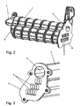
- the exhaust gas cooler of the embodiment according to Fig. 1 to Fig. 3 comprises a housing 1, which is traversed by a cooling liquid in the manner of a water jacket (coolant connections not shown).
- the cooling liquid may be connected to an engine cooling circuit or else to a separate low-temperature cooling circuit.
- each is a diesel engine for a motor vehicle, in particular a passenger car.
- the filter element 3 comprises a tube part 3a and a filter insert 3b defined therein by soldering or welding, which is approximately in the drawings 4 and FIG. 5 is shown schematically. Both the exchanger tubes 2 and the tube part 3 a of the filter element 3 are each fixed in the same perforated bottom part 4, for example by welding.
- the exhaust gas cooler is designed as a U-flow cooler and has an inlet side, according to Fig. 1 a connection member 5 with a feed 5a and a Outlet 5b is screwed for the exhaust gas on the inlet-side bottom part 4.
- a deflection region 6 is fixed on the bottom part there.
- the exhaust gas thus flows through the exhaust gas cooler first in an execution through the filter member, is then deflected in the deflection region 6 by 180 ° and flows through the exhaust gas cooler in the return direction through the exchanger tubes.
- the deflection region 6 is formed as a hollow chamber, into which also a bypass channel 7 opens.
- a bypass channel 7 opens.
- the exhaust gas cooler according to the present embodiments consists predominantly of corrosion-resistant steel. Depending on the exhaust gas temperature and design, at least some parts may also be made of aluminum or plastic (eg the water jacket 1).
- the exhaust gas cooler is integrated in an overall system in which the exhaust gas recirculation is designed as a low-pressure feedback.
- the exhaust gas cooler upstream of a regenerable Pumbleflter upstream and downstream of the air side of an exhaust gas turbocharger.
- the admixture of the exhaust gas to the combustion air of the engine takes place here before the compression by the turbocharger.
- the filter member 3 is formed as a non-regenerable permanent filter, which is designed for the entire life of the vehicle.
- a mesh size of the filter is designed so that only particles of a size that could endanger the turbocharger are filtered out.
- Fig. 5 corresponds to the example except for the arrangement of the exchanger tubes Fig. 4 ,
- Fig. 5 are the two end-face floor parts 4 and the cavity of the deflection 6 particularly clearly visible, for better clarity, only one of the exchanger tubes 3 is shown.
Landscapes
- Engineering & Computer Science (AREA)
- Mechanical Engineering (AREA)
- General Engineering & Computer Science (AREA)
- Chemical & Material Sciences (AREA)
- Combustion & Propulsion (AREA)
- Physics & Mathematics (AREA)
- Thermal Sciences (AREA)
- Chemical Kinetics & Catalysis (AREA)
- Exhaust-Gas Circulating Devices (AREA)
- Exhaust Gas After Treatment (AREA)
Claims (9)
- Refroidisseur de gaz d'échappement pour un moteur à combustion interne, comprenant une pluralité de conduits d'écoulement (2, 3) guidant les gaz d'échappement, où les conduits d'écoulement (2, 3) sont disposés à l'intérieur d'un carter (1) et sont en échange thermique avec un fluide servant au refroidissement des gaz d'échappement, où au moins un élément filtrant (3), servant au filtrage de particules provenant du flux de gaz d'échappement, est structurellement intégré au refroidisseur de gaz d'échappement,
caractérisé en ce que le refroidisseur de gaz d'échappement peut être traversé par les gaz d'échappement, au soins respectivement une fois dans une direction aller et dans une direction retour, où l'élément filtrant (3) est prévu dans au moins l'une des deux directions, à savoir la direction aller ou la direction retour, et en particulier un unique conquit d'écoulement de la direction aller est configuré comme une partie de tube (3a) formant l'élément filtrant (3), une pluralité de conduits d'écoulement de la direction retour étant configurée comme un faisceau de tubes échangeurs (2). - Refroidisseur de gaz d'échappement selon la revendication 1, caractérisé en ce que l'élément filtrant (3) est disposé à l'intérieur du carter (1), le carter (1) pouvant en particulier être traversé par le fluide.
- Refroidisseur de gaz d'échappement selon la revendication 1 ou 2, caractérisé en ce que la partie de tube (3a) et / ou le faisceau de tubes échangeurs (2) sont logés dans des parties d'extrémité (4) de la plaque tubulaire.
- Refroidisseur de gaz d'échappement selon l'une quelconque des revendications 1 à 3, caractérisé en ce qu'une zone de retour de flux (6) servant à changer la direction d'écoulement des gaz d'échappement est configurée au niveau d'une face frontale du refroidisseur de gaz d'échappement.
- Refroidisseur de gaz d'échappement selon l'une quelconque des revendications précédentes, caractérisé en ce que l'élément filtrant (3) est configuré comme une partie de tube (3a) comportant une cartouche filtrante (3b) fixée à l'intérieur de ladite partie de tube.
- Refroidisseur de gaz d'échappement selon l'une quelconque des revendications précédentes, caractérisé en ce qu'il est prévu une conduits de dérivation (7) prouvant être traversée par des gaz d'échappement, où la conduite de dérivation (7) se ramifie en particulier en aval de l'élément filtrant (3) et en amont de la pluralité de conduits d'écoulement (2).
- Refroidisseur de gaz d'échappement selon l'une quelconque des revendications précédentes, caractérisé en ce que l'élément filtrant (3) est conçu comme un filtre permanent non régénérable en cours de fonctionnement.
- Refroidisseur de gaz d'échappement selon l'une quelconque des revendications précédentes, caractérisé en ce que le refroidisseur de gaz d'échappement est configuré pour un agencement en naval d'un filtre à particules.
- Refroidisseur de gaz d'échappement selon l'une quelconque des revendications précédentes, caractérisé en ce que le refroidisseur de gaz d'échappement est configuré pour un agencement en amont d'un turbocompresseur.
Priority Applications (3)
| Application Number | Priority Date | Filing Date | Title |
|---|---|---|---|
| AT08291142T ATE556284T1 (de) | 2008-12-03 | 2008-12-03 | Abgaskühler mit integrierten partikelfilter für einen verbrennungsmotor |
| EP08291142A EP2194351B1 (fr) | 2008-12-03 | 2008-12-03 | Refroidisseur de gaz d'échappement avec un filtre intégré pour un moteur à combustion |
| US12/591,669 US20100132346A1 (en) | 2008-12-03 | 2009-11-27 | Exhaust-gas cooler for an internal combustion engine |
Applications Claiming Priority (1)
| Application Number | Priority Date | Filing Date | Title |
|---|---|---|---|
| EP08291142A EP2194351B1 (fr) | 2008-12-03 | 2008-12-03 | Refroidisseur de gaz d'échappement avec un filtre intégré pour un moteur à combustion |
Publications (2)
| Publication Number | Publication Date |
|---|---|
| EP2194351A1 EP2194351A1 (fr) | 2010-06-09 |
| EP2194351B1 true EP2194351B1 (fr) | 2012-05-02 |
Family
ID=40602246
Family Applications (1)
| Application Number | Title | Priority Date | Filing Date |
|---|---|---|---|
| EP08291142A Not-in-force EP2194351B1 (fr) | 2008-12-03 | 2008-12-03 | Refroidisseur de gaz d'échappement avec un filtre intégré pour un moteur à combustion |
Country Status (3)
| Country | Link |
|---|---|
| US (1) | US20100132346A1 (fr) |
| EP (1) | EP2194351B1 (fr) |
| AT (1) | ATE556284T1 (fr) |
Cited By (8)
| Publication number | Priority date | Publication date | Assignee | Title |
|---|---|---|---|---|
| EP2801709A1 (fr) | 2013-05-08 | 2014-11-12 | MAHLE Behr GmbH & Co. KG | Refroidisseur de gaz d'échappement |
| WO2016097197A1 (fr) | 2014-12-17 | 2016-06-23 | Tenneco Gmbh | Système rge comportant un filtre à particules pour un moteur à essence |
| DE102015108224A1 (de) | 2014-12-17 | 2016-06-23 | Tenneco Gmbh | AGR-System mit Partikelfilter für Ottomotor |
| DE102015108223A1 (de) | 2015-05-26 | 2016-12-01 | Tenneco Gmbh | AGR-System mit Partikelfilter und Wastegate |
| WO2016189028A1 (fr) | 2015-05-26 | 2016-12-01 | Tenneco Gmbh | Système rge présentant un filtre à particules et une soupape de décharge |
| WO2017108615A1 (fr) | 2015-12-21 | 2017-06-29 | Valeo Termico, S.A. | Ensemble unité de conduite de gaz avec filtre à particules, procédé de fabrication de celui-ci et échangeur thermique pour gaz, en particulier pour les gaz d'échappement d'un moteur |
| US10480460B2 (en) | 2014-12-17 | 2019-11-19 | Tenneco Gmbh | EGR system with particle filter for a gasoline engine |
| US10502166B2 (en) | 2015-05-26 | 2019-12-10 | Tenneco Gmbh | EGR system with particle filter and wastegate |
Families Citing this family (15)
| Publication number | Priority date | Publication date | Assignee | Title |
|---|---|---|---|---|
| DE202009001782U1 (de) * | 2009-02-12 | 2010-07-08 | Mann+Hummel Gmbh | Abgasansaugvorrichtung |
| EP2667007B1 (fr) * | 2009-07-10 | 2015-04-15 | MAHLE Behr GmbH & Co. KG | Echangeur thermique, système de recyclage des gaz d'échappement et moteur à combustion interne |
| EP2463490B1 (fr) * | 2010-12-10 | 2015-09-09 | Perkins Engines Company Limited | Améliorations de ou liées à des refroidisseurs de gaz pour moteurs à combustion interne |
| DE102011001461B4 (de) | 2011-03-22 | 2017-01-26 | Pierburg Gmbh | Abgasrückführmodul für eine Verbrennungskraftmaschine |
| ES2421185B1 (es) | 2012-02-22 | 2014-08-11 | Valeo Térmico, S. A. | Intercambiador de calor para gases, en especial de los gases de escape de un motor |
| US20150136369A1 (en) * | 2012-06-08 | 2015-05-21 | International Engine Intellectual Property Company Llc | Egr cooler header casting |
| CN102900570B (zh) * | 2012-09-20 | 2014-11-12 | 浙江银轮机械股份有限公司 | 一种u型egr冷却器 |
| EP2781730A1 (fr) | 2013-03-19 | 2014-09-24 | Borgwarner Inc. | Dispositif compact pour gestion de gaz d'échappement dans un système EGR |
| DE102013211221A1 (de) * | 2013-06-14 | 2014-12-18 | Behr Gmbh & Co. Kg | Wärmeübertrager |
| ES2531124B1 (es) | 2013-09-10 | 2016-01-22 | Valeo Térmico, S. A. | Intercambiador de calor para gases, en especial de los gases de escape de un motor |
| US20160215735A1 (en) * | 2013-09-11 | 2016-07-28 | International Engine Intellectual Property Company, Llc | Thermal screen for an egr cooler |
| DE102015217541B4 (de) * | 2015-09-14 | 2017-04-06 | Magna powertrain gmbh & co kg | Kühleranordnung für ein Kraftfahrzeug |
| DE102016109247B4 (de) * | 2016-05-19 | 2020-03-26 | Benteler Automobiltechnik Gmbh | Abgaswärmeübertrager |
| US10215135B2 (en) * | 2016-07-22 | 2019-02-26 | Ford Global Technologies, Llc | System and methods for extracting water from exhaust gases for water injection |
| JP2021055856A (ja) * | 2019-09-27 | 2021-04-08 | 株式会社ユタカ技研 | 熱交換器 |
Family Cites Families (4)
| Publication number | Priority date | Publication date | Assignee | Title |
|---|---|---|---|---|
| DE102005029322A1 (de) * | 2005-06-24 | 2006-12-28 | Behr Gmbh & Co. Kg | Vorrichtung zur Rückführung und Kühlung von Abgas für eine Brennkraftmaschine |
| DE102006038706B4 (de) * | 2006-08-18 | 2018-12-27 | Volkswagen Ag | Brennkraftmaschine mit Niederdruck-Abgasrückführung |
| DE102007054913A1 (de) * | 2006-11-15 | 2008-08-28 | Behr Gmbh & Co. Kg | Wärmeübertrager |
| DE102007025704A1 (de) * | 2007-06-01 | 2008-12-04 | Volkswagen Ag | Brennkraftmaschine mit ND-EGR-Leitung |
-
2008
- 2008-12-03 EP EP08291142A patent/EP2194351B1/fr not_active Not-in-force
- 2008-12-03 AT AT08291142T patent/ATE556284T1/de active
-
2009
- 2009-11-27 US US12/591,669 patent/US20100132346A1/en not_active Abandoned
Cited By (11)
| Publication number | Priority date | Publication date | Assignee | Title |
|---|---|---|---|---|
| EP2801709A1 (fr) | 2013-05-08 | 2014-11-12 | MAHLE Behr GmbH & Co. KG | Refroidisseur de gaz d'échappement |
| DE102013208436A1 (de) | 2013-05-08 | 2014-11-13 | MAHLE Behr GmbH & Co. KG | Abgaskühler |
| WO2016097197A1 (fr) | 2014-12-17 | 2016-06-23 | Tenneco Gmbh | Système rge comportant un filtre à particules pour un moteur à essence |
| DE102014118813A1 (de) | 2014-12-17 | 2016-06-23 | Tenneco Gmbh | AGR-System mit Partikelfilter für Ottomotor |
| DE102015108224A1 (de) | 2014-12-17 | 2016-06-23 | Tenneco Gmbh | AGR-System mit Partikelfilter für Ottomotor |
| US10480460B2 (en) | 2014-12-17 | 2019-11-19 | Tenneco Gmbh | EGR system with particle filter for a gasoline engine |
| DE102015108223A1 (de) | 2015-05-26 | 2016-12-01 | Tenneco Gmbh | AGR-System mit Partikelfilter und Wastegate |
| WO2016189028A1 (fr) | 2015-05-26 | 2016-12-01 | Tenneco Gmbh | Système rge présentant un filtre à particules et une soupape de décharge |
| DE102015108223B4 (de) | 2015-05-26 | 2018-04-19 | Tenneco Gmbh | AGR-System mit Partikelfilter und Wastegate |
| US10502166B2 (en) | 2015-05-26 | 2019-12-10 | Tenneco Gmbh | EGR system with particle filter and wastegate |
| WO2017108615A1 (fr) | 2015-12-21 | 2017-06-29 | Valeo Termico, S.A. | Ensemble unité de conduite de gaz avec filtre à particules, procédé de fabrication de celui-ci et échangeur thermique pour gaz, en particulier pour les gaz d'échappement d'un moteur |
Also Published As
| Publication number | Publication date |
|---|---|
| ATE556284T1 (de) | 2012-05-15 |
| US20100132346A1 (en) | 2010-06-03 |
| EP2194351A1 (fr) | 2010-06-09 |
Similar Documents
| Publication | Publication Date | Title |
|---|---|---|
| EP2194351B1 (fr) | Refroidisseur de gaz d'échappement avec un filtre intégré pour un moteur à combustion | |
| EP2667007B1 (fr) | Echangeur thermique, système de recyclage des gaz d'échappement et moteur à combustion interne | |
| EP2020501B1 (fr) | Boîtier d'échangeur thermique, échangeur thermique ou composant doté d'un ou plusieurs échangeurs thermiques, système de récupération des gaz d'échappement, système d'alimentation en air de suralimentation et utilisation de l'échangeur thermique | |
| DE102005014385A1 (de) | Abgaswärmeübertrager, insbesondere Abgaskühler für Abgasrückführung in Kraftfahrzeugen | |
| EP1857761B1 (fr) | Unité de transmission de la chaleur pour moteurs à combustion interne | |
| DE102005029322A1 (de) | Vorrichtung zur Rückführung und Kühlung von Abgas für eine Brennkraftmaschine | |
| WO2007104491A1 (fr) | Échangeur thermique pour véhicule automobile | |
| DE102013205267A1 (de) | Luft-Flüssigkeits-Wärmetauscher | |
| DE102006033314A1 (de) | Wärmetauschersystem und Verfahren zum Betreiben eines derartigen Wärmetauschersystems | |
| WO2008101978A1 (fr) | Module de gaz frais conçu pour une installation de gaz frais | |
| DE102013202056A1 (de) | Frischluftversorgungseinrichtung einer Brennkraftmaschine | |
| DE102015009501A1 (de) | Brennkraftmaschinenkühlung | |
| DE112004000310B3 (de) | Motorbremsanlage einer Mehrzylinderbrennkraftmaschine mit gekühltem Zwischenrohr für Gaswechsel zwischen Zylindern beim Motorbremsen | |
| EP2324227B1 (fr) | Système de refroidissement des gaz d'échappement d'un véhicule automobile | |
| DE102007051659A1 (de) | Vorrichtung und Verfahren zur Rückführung von Abgas eines Verbrennungsmotors | |
| WO2012143462A2 (fr) | Refroidisseur de gaz d'échappement pour refroidir les gaz d'échappement de combustion d'un moteur à combustion interne, adaptateur de collecteur d'eau, système de refroidissement de gaz d'échappement et procédé de production d'un système de refroidissement de gaz d'échappement | |
| DE102018002584A1 (de) | Verbrennungskraftmaschine für ein Kraftfahrzeug, mit einem Kühlmittelkreislauf und einer zugehörigen Ventileinrichtung | |
| DE102010033718B4 (de) | Kraftwagen mit einer Verbrennungskraftmaschine | |
| WO2008058737A1 (fr) | Dispositif de recyclage des gaz d'échappement | |
| DE102012206974A1 (de) | Abgasrückführungsanlage | |
| WO1999046489A1 (fr) | Conduite pour gaz d'echappement refroidie par eau | |
| DE102008062145A1 (de) | Motor mit Turbo-Superlader | |
| DE102005036045B4 (de) | Kühlvorrichtung für Verbrennungskraftmaschinen | |
| DE102005041732A1 (de) | Brennkraftmaschine mit Abgaskühlsystem | |
| EP1975400B1 (fr) | Dispositif de refroidissement pour gaz d'échappement recyclé |
Legal Events
| Date | Code | Title | Description |
|---|---|---|---|
| PUAI | Public reference made under article 153(3) epc to a published international application that has entered the european phase |
Free format text: ORIGINAL CODE: 0009012 |
|
| AK | Designated contracting states |
Kind code of ref document: A1 Designated state(s): AT BE BG CH CY CZ DE DK EE ES FI FR GB GR HR HU IE IS IT LI LT LU LV MC MT NL NO PL PT RO SE SI SK TR |
|
| AX | Request for extension of the european patent |
Extension state: AL BA MK RS |
|
| 17P | Request for examination filed |
Effective date: 20101209 |
|
| AKX | Designation fees paid |
Designated state(s): AT BE BG CH CY CZ DE DK EE ES FI FR GB GR HR HU IE IS IT LI LT LU LV MC MT NL NO PL PT RO SE SI SK TR |
|
| 17Q | First examination report despatched |
Effective date: 20110124 |
|
| GRAP | Despatch of communication of intention to grant a patent |
Free format text: ORIGINAL CODE: EPIDOSNIGR1 |
|
| GRAS | Grant fee paid |
Free format text: ORIGINAL CODE: EPIDOSNIGR3 |
|
| GRAA | (expected) grant |
Free format text: ORIGINAL CODE: 0009210 |
|
| AK | Designated contracting states |
Kind code of ref document: B1 Designated state(s): AT BE BG CH CY CZ DE DK EE ES FI FR GB GR HR HU IE IS IT LI LT LU LV MC MT NL NO PL PT RO SE SI SK TR |
|
| REG | Reference to a national code |
Ref country code: GB Ref legal event code: FG4D Free format text: NOT ENGLISH |
|
| REG | Reference to a national code |
Ref country code: AT Ref legal event code: REF Ref document number: 556284 Country of ref document: AT Kind code of ref document: T Effective date: 20120515 Ref country code: CH Ref legal event code: EP |
|
| REG | Reference to a national code |
Ref country code: IE Ref legal event code: FG4D Free format text: LANGUAGE OF EP DOCUMENT: GERMAN |
|
| REG | Reference to a national code |
Ref country code: DE Ref legal event code: R096 Ref document number: 502008007118 Country of ref document: DE Effective date: 20120628 |
|
| REG | Reference to a national code |
Ref country code: NL Ref legal event code: VDEP Effective date: 20120502 |
|
| REG | Reference to a national code |
Ref country code: LT Ref legal event code: MG4D Effective date: 20120502 |
|
| PG25 | Lapsed in a contracting state [announced via postgrant information from national office to epo] |
Ref country code: IS Free format text: LAPSE BECAUSE OF FAILURE TO SUBMIT A TRANSLATION OF THE DESCRIPTION OR TO PAY THE FEE WITHIN THE PRESCRIBED TIME-LIMIT Effective date: 20120902 Ref country code: NO Free format text: LAPSE BECAUSE OF FAILURE TO SUBMIT A TRANSLATION OF THE DESCRIPTION OR TO PAY THE FEE WITHIN THE PRESCRIBED TIME-LIMIT Effective date: 20120802 Ref country code: CY Free format text: LAPSE BECAUSE OF FAILURE TO SUBMIT A TRANSLATION OF THE DESCRIPTION OR TO PAY THE FEE WITHIN THE PRESCRIBED TIME-LIMIT Effective date: 20120502 Ref country code: SE Free format text: LAPSE BECAUSE OF FAILURE TO SUBMIT A TRANSLATION OF THE DESCRIPTION OR TO PAY THE FEE WITHIN THE PRESCRIBED TIME-LIMIT Effective date: 20120502 Ref country code: PL Free format text: LAPSE BECAUSE OF FAILURE TO SUBMIT A TRANSLATION OF THE DESCRIPTION OR TO PAY THE FEE WITHIN THE PRESCRIBED TIME-LIMIT Effective date: 20120502 Ref country code: FI Free format text: LAPSE BECAUSE OF FAILURE TO SUBMIT A TRANSLATION OF THE DESCRIPTION OR TO PAY THE FEE WITHIN THE PRESCRIBED TIME-LIMIT Effective date: 20120502 Ref country code: LT Free format text: LAPSE BECAUSE OF FAILURE TO SUBMIT A TRANSLATION OF THE DESCRIPTION OR TO PAY THE FEE WITHIN THE PRESCRIBED TIME-LIMIT Effective date: 20120502 |
|
| PG25 | Lapsed in a contracting state [announced via postgrant information from national office to epo] |
Ref country code: GR Free format text: LAPSE BECAUSE OF FAILURE TO SUBMIT A TRANSLATION OF THE DESCRIPTION OR TO PAY THE FEE WITHIN THE PRESCRIBED TIME-LIMIT Effective date: 20120803 Ref country code: SI Free format text: LAPSE BECAUSE OF FAILURE TO SUBMIT A TRANSLATION OF THE DESCRIPTION OR TO PAY THE FEE WITHIN THE PRESCRIBED TIME-LIMIT Effective date: 20120502 Ref country code: LV Free format text: LAPSE BECAUSE OF FAILURE TO SUBMIT A TRANSLATION OF THE DESCRIPTION OR TO PAY THE FEE WITHIN THE PRESCRIBED TIME-LIMIT Effective date: 20120502 Ref country code: PT Free format text: LAPSE BECAUSE OF FAILURE TO SUBMIT A TRANSLATION OF THE DESCRIPTION OR TO PAY THE FEE WITHIN THE PRESCRIBED TIME-LIMIT Effective date: 20120903 Ref country code: HR Free format text: LAPSE BECAUSE OF FAILURE TO SUBMIT A TRANSLATION OF THE DESCRIPTION OR TO PAY THE FEE WITHIN THE PRESCRIBED TIME-LIMIT Effective date: 20120502 |
|
| PG25 | Lapsed in a contracting state [announced via postgrant information from national office to epo] |
Ref country code: DK Free format text: LAPSE BECAUSE OF FAILURE TO SUBMIT A TRANSLATION OF THE DESCRIPTION OR TO PAY THE FEE WITHIN THE PRESCRIBED TIME-LIMIT Effective date: 20120502 Ref country code: NL Free format text: LAPSE BECAUSE OF FAILURE TO SUBMIT A TRANSLATION OF THE DESCRIPTION OR TO PAY THE FEE WITHIN THE PRESCRIBED TIME-LIMIT Effective date: 20120502 Ref country code: RO Free format text: LAPSE BECAUSE OF FAILURE TO SUBMIT A TRANSLATION OF THE DESCRIPTION OR TO PAY THE FEE WITHIN THE PRESCRIBED TIME-LIMIT Effective date: 20120502 Ref country code: CZ Free format text: LAPSE BECAUSE OF FAILURE TO SUBMIT A TRANSLATION OF THE DESCRIPTION OR TO PAY THE FEE WITHIN THE PRESCRIBED TIME-LIMIT Effective date: 20120502 Ref country code: EE Free format text: LAPSE BECAUSE OF FAILURE TO SUBMIT A TRANSLATION OF THE DESCRIPTION OR TO PAY THE FEE WITHIN THE PRESCRIBED TIME-LIMIT Effective date: 20120502 Ref country code: SK Free format text: LAPSE BECAUSE OF FAILURE TO SUBMIT A TRANSLATION OF THE DESCRIPTION OR TO PAY THE FEE WITHIN THE PRESCRIBED TIME-LIMIT Effective date: 20120502 |
|
| PG25 | Lapsed in a contracting state [announced via postgrant information from national office to epo] |
Ref country code: IT Free format text: LAPSE BECAUSE OF FAILURE TO SUBMIT A TRANSLATION OF THE DESCRIPTION OR TO PAY THE FEE WITHIN THE PRESCRIBED TIME-LIMIT Effective date: 20120502 |
|
| PLBE | No opposition filed within time limit |
Free format text: ORIGINAL CODE: 0009261 |
|
| STAA | Information on the status of an ep patent application or granted ep patent |
Free format text: STATUS: NO OPPOSITION FILED WITHIN TIME LIMIT |
|
| 26N | No opposition filed |
Effective date: 20130205 |
|
| PG25 | Lapsed in a contracting state [announced via postgrant information from national office to epo] |
Ref country code: ES Free format text: LAPSE BECAUSE OF FAILURE TO SUBMIT A TRANSLATION OF THE DESCRIPTION OR TO PAY THE FEE WITHIN THE PRESCRIBED TIME-LIMIT Effective date: 20120813 |
|
| REG | Reference to a national code |
Ref country code: DE Ref legal event code: R097 Ref document number: 502008007118 Country of ref document: DE Effective date: 20130205 |
|
| BERE | Be: lapsed |
Owner name: BEHR G.M.B.H. & CO. KG Effective date: 20121231 Owner name: BEHR FRANCE ROUFFACH SAS Effective date: 20121231 |
|
| PG25 | Lapsed in a contracting state [announced via postgrant information from national office to epo] |
Ref country code: MC Free format text: LAPSE BECAUSE OF NON-PAYMENT OF DUE FEES Effective date: 20121231 Ref country code: BG Free format text: LAPSE BECAUSE OF FAILURE TO SUBMIT A TRANSLATION OF THE DESCRIPTION OR TO PAY THE FEE WITHIN THE PRESCRIBED TIME-LIMIT Effective date: 20120802 |
|
| REG | Reference to a national code |
Ref country code: CH Ref legal event code: PL |
|
| REG | Reference to a national code |
Ref country code: IE Ref legal event code: MM4A |
|
| PG25 | Lapsed in a contracting state [announced via postgrant information from national office to epo] |
Ref country code: BE Free format text: LAPSE BECAUSE OF NON-PAYMENT OF DUE FEES Effective date: 20121231 |
|
| PG25 | Lapsed in a contracting state [announced via postgrant information from national office to epo] |
Ref country code: CH Free format text: LAPSE BECAUSE OF NON-PAYMENT OF DUE FEES Effective date: 20121231 Ref country code: LI Free format text: LAPSE BECAUSE OF NON-PAYMENT OF DUE FEES Effective date: 20121231 Ref country code: IE Free format text: LAPSE BECAUSE OF NON-PAYMENT OF DUE FEES Effective date: 20121203 |
|
| PG25 | Lapsed in a contracting state [announced via postgrant information from national office to epo] |
Ref country code: MT Free format text: LAPSE BECAUSE OF FAILURE TO SUBMIT A TRANSLATION OF THE DESCRIPTION OR TO PAY THE FEE WITHIN THE PRESCRIBED TIME-LIMIT Effective date: 20120502 |
|
| PG25 | Lapsed in a contracting state [announced via postgrant information from national office to epo] |
Ref country code: TR Free format text: LAPSE BECAUSE OF FAILURE TO SUBMIT A TRANSLATION OF THE DESCRIPTION OR TO PAY THE FEE WITHIN THE PRESCRIBED TIME-LIMIT Effective date: 20120502 |
|
| PG25 | Lapsed in a contracting state [announced via postgrant information from national office to epo] |
Ref country code: LU Free format text: LAPSE BECAUSE OF NON-PAYMENT OF DUE FEES Effective date: 20121203 |
|
| PG25 | Lapsed in a contracting state [announced via postgrant information from national office to epo] |
Ref country code: HU Free format text: LAPSE BECAUSE OF FAILURE TO SUBMIT A TRANSLATION OF THE DESCRIPTION OR TO PAY THE FEE WITHIN THE PRESCRIBED TIME-LIMIT Effective date: 20081203 |
|
| REG | Reference to a national code |
Ref country code: AT Ref legal event code: MM01 Ref document number: 556284 Country of ref document: AT Kind code of ref document: T Effective date: 20131203 |
|
| PG25 | Lapsed in a contracting state [announced via postgrant information from national office to epo] |
Ref country code: AT Free format text: LAPSE BECAUSE OF NON-PAYMENT OF DUE FEES Effective date: 20131203 |
|
| REG | Reference to a national code |
Ref country code: DE Ref legal event code: R082 Ref document number: 502008007118 Country of ref document: DE Representative=s name: GRAUEL, ANDREAS, DIPL.-PHYS. DR. RER. NAT., DE Ref country code: DE Ref legal event code: R081 Ref document number: 502008007118 Country of ref document: DE Owner name: MAHLE INTERNATIONAL GMBH, DE Free format text: FORMER OWNERS: BEHR GMBH & CO. KG, 70469 STUTTGART, DE; BEHR FRANCE ROUFFACH S.A.S., ROUFFACH, FR |
|
| REG | Reference to a national code |
Ref country code: FR Ref legal event code: PLFP Year of fee payment: 8 |
|
| REG | Reference to a national code |
Ref country code: FR Ref legal event code: PLFP Year of fee payment: 9 |
|
| REG | Reference to a national code |
Ref country code: FR Ref legal event code: PLFP Year of fee payment: 10 |
|
| PGFP | Annual fee paid to national office [announced via postgrant information from national office to epo] |
Ref country code: FR Payment date: 20191220 Year of fee payment: 12 |
|
| PGFP | Annual fee paid to national office [announced via postgrant information from national office to epo] |
Ref country code: GB Payment date: 20191220 Year of fee payment: 12 Ref country code: DE Payment date: 20200220 Year of fee payment: 12 |
|
| REG | Reference to a national code |
Ref country code: DE Ref legal event code: R119 Ref document number: 502008007118 Country of ref document: DE |
|
| GBPC | Gb: european patent ceased through non-payment of renewal fee |
Effective date: 20201203 |
|
| PG25 | Lapsed in a contracting state [announced via postgrant information from national office to epo] |
Ref country code: FR Free format text: LAPSE BECAUSE OF NON-PAYMENT OF DUE FEES Effective date: 20201231 |
|
| PG25 | Lapsed in a contracting state [announced via postgrant information from national office to epo] |
Ref country code: GB Free format text: LAPSE BECAUSE OF NON-PAYMENT OF DUE FEES Effective date: 20201203 Ref country code: DE Free format text: LAPSE BECAUSE OF NON-PAYMENT OF DUE FEES Effective date: 20210701 |