EP2194314A1 - Leuchte - Google Patents
Leuchte Download PDFInfo
- Publication number
- EP2194314A1 EP2194314A1 EP09014108A EP09014108A EP2194314A1 EP 2194314 A1 EP2194314 A1 EP 2194314A1 EP 09014108 A EP09014108 A EP 09014108A EP 09014108 A EP09014108 A EP 09014108A EP 2194314 A1 EP2194314 A1 EP 2194314A1
- Authority
- EP
- European Patent Office
- Prior art keywords
- luminaire according
- light
- reflector
- front side
- boom
- Prior art date
- Legal status (The legal status is an assumption and is not a legal conclusion. Google has not performed a legal analysis and makes no representation as to the accuracy of the status listed.)
- Granted
Links
- 229910052751 metal Inorganic materials 0.000 claims description 6
- 239000002184 metal Substances 0.000 claims description 6
- 229920003023 plastic Polymers 0.000 claims description 5
- 230000001154 acute effect Effects 0.000 claims description 2
- 230000003287 optical effect Effects 0.000 claims 1
- 239000000463 material Substances 0.000 description 3
- 241000238631 Hexapoda Species 0.000 description 2
- 230000000694 effects Effects 0.000 description 2
- 229910052782 aluminium Inorganic materials 0.000 description 1
- XAGFODPZIPBFFR-UHFFFAOYSA-N aluminium Chemical compound [Al] XAGFODPZIPBFFR-UHFFFAOYSA-N 0.000 description 1
- 230000005540 biological transmission Effects 0.000 description 1
- 239000004020 conductor Substances 0.000 description 1
- 238000010276 construction Methods 0.000 description 1
- 238000011161 development Methods 0.000 description 1
- 230000018109 developmental process Effects 0.000 description 1
- 239000000428 dust Substances 0.000 description 1
- 238000005265 energy consumption Methods 0.000 description 1
- 238000010304 firing Methods 0.000 description 1
- 230000004313 glare Effects 0.000 description 1
- 238000012423 maintenance Methods 0.000 description 1
- 230000035515 penetration Effects 0.000 description 1
- 238000004080 punching Methods 0.000 description 1
- 238000009423 ventilation Methods 0.000 description 1
Images

Classifications
-
- F—MECHANICAL ENGINEERING; LIGHTING; HEATING; WEAPONS; BLASTING
- F21—LIGHTING
- F21V—FUNCTIONAL FEATURES OR DETAILS OF LIGHTING DEVICES OR SYSTEMS THEREOF; STRUCTURAL COMBINATIONS OF LIGHTING DEVICES WITH OTHER ARTICLES, NOT OTHERWISE PROVIDED FOR
- F21V21/00—Supporting, suspending, or attaching arrangements for lighting devices; Hand grips
- F21V21/10—Pendants, arms, or standards; Fixing lighting devices to pendants, arms, or standards
-
- F—MECHANICAL ENGINEERING; LIGHTING; HEATING; WEAPONS; BLASTING
- F21—LIGHTING
- F21S—NON-PORTABLE LIGHTING DEVICES; SYSTEMS THEREOF; VEHICLE LIGHTING DEVICES SPECIALLY ADAPTED FOR VEHICLE EXTERIORS
- F21S6/00—Lighting devices intended to be free-standing
- F21S6/005—Lighting devices intended to be free-standing with a lamp housing maintained at a distance from the floor or ground via a support, e.g. standing lamp for ambient lighting
-
- F—MECHANICAL ENGINEERING; LIGHTING; HEATING; WEAPONS; BLASTING
- F21—LIGHTING
- F21V—FUNCTIONAL FEATURES OR DETAILS OF LIGHTING DEVICES OR SYSTEMS THEREOF; STRUCTURAL COMBINATIONS OF LIGHTING DEVICES WITH OTHER ARTICLES, NOT OTHERWISE PROVIDED FOR
- F21V15/00—Protecting lighting devices from damage
- F21V15/01—Housings, e.g. material or assembling of housing parts
-
- F—MECHANICAL ENGINEERING; LIGHTING; HEATING; WEAPONS; BLASTING
- F21—LIGHTING
- F21V—FUNCTIONAL FEATURES OR DETAILS OF LIGHTING DEVICES OR SYSTEMS THEREOF; STRUCTURAL COMBINATIONS OF LIGHTING DEVICES WITH OTHER ARTICLES, NOT OTHERWISE PROVIDED FOR
- F21V5/00—Refractors for light sources
- F21V5/002—Refractors for light sources using microoptical elements for redirecting or diffusing light
-
- F—MECHANICAL ENGINEERING; LIGHTING; HEATING; WEAPONS; BLASTING
- F21—LIGHTING
- F21V—FUNCTIONAL FEATURES OR DETAILS OF LIGHTING DEVICES OR SYSTEMS THEREOF; STRUCTURAL COMBINATIONS OF LIGHTING DEVICES WITH OTHER ARTICLES, NOT OTHERWISE PROVIDED FOR
- F21V5/00—Refractors for light sources
- F21V5/02—Refractors for light sources of prismatic shape
-
- F—MECHANICAL ENGINEERING; LIGHTING; HEATING; WEAPONS; BLASTING
- F21—LIGHTING
- F21Y—INDEXING SCHEME ASSOCIATED WITH SUBCLASSES F21K, F21L, F21S and F21V, RELATING TO THE FORM OR THE KIND OF THE LIGHT SOURCES OR OF THE COLOUR OF THE LIGHT EMITTED
- F21Y2103/00—Elongate light sources, e.g. fluorescent tubes
-
- F—MECHANICAL ENGINEERING; LIGHTING; HEATING; WEAPONS; BLASTING
- F21—LIGHTING
- F21Y—INDEXING SCHEME ASSOCIATED WITH SUBCLASSES F21K, F21L, F21S and F21V, RELATING TO THE FORM OR THE KIND OF THE LIGHT SOURCES OR OF THE COLOUR OF THE LIGHT EMITTED
- F21Y2113/00—Combination of light sources
Definitions
- the invention relates to a luminaire according to the preamble of claim 1.
- Such a lamp is marketed for example as a floor lamp under the brand name Opura by the applicant. It is characterized by its appearance, which is essentially characterized by its appearance.
- This optic is formed from a hollow body and radiating on all sides.
- the lamps used are single-capped fluorescent lamps whose sockets are mounted directly on the device carrier.
- the equipment rack accommodates components for operating the fluorescent lamps, such as terminals and electronic ballasts.
- the object of the invention is to provide a luminaire of the type mentioned in such a way that it can be used with different light sources. It is important to ensure that the functioning of the omnidirectional optics is maintained.
- the core of the invention is that at least one boom is attached to the equipment carrier and that at least one socket for a light source is mounted on the boom.
- the boom is made translucent, at least in some areas. This ensures that the light generated by the bulb in all Areas of the hollow body is radiated and thus the entire look acts as a luminous body, which emits light on all sides.
- two single-ended gas discharge lamps are provided as lighting means. Further, two arms are connected on both sides in the end regions with the equipment carrier, wherein each of the cantilevers carries a socket and in each of the cantilevers in the region in which the socket is arranged at one arm, the other arm a translucent area, in particular an opening , is located.
- the gas discharge lamps can protrude with their free ends through these openings. The so-called Coolspot, the coolest point of the gas discharge lamp, is located near the free end in this type of lamp.
- this area is closely enclosed by the boom, at least when the boom is made of good heat-conducting material, it can be assumed that this point remains at a low temperature level compared to a freestanding lamp and thus optimizes the efficiency of the lamp and thus of the luminaire is.
- the boom extends substantially over the entire length of the device carrier.
- This boom is made of perforated sheet metal or translucent plastic to allow in this way the all-round light emission. Frames can thus be mounted on the boom.
- double ended lamps can also be used for the luminaire according to the invention.
- two single-ended gas discharge lamps are again provided as lighting means, wherein the arm extends substantially over the entire length of the equipment carrier.
- a light-transmitting area in particular an opening, is present.
- Such an opening may also be formed by a free punching or release.
- the boom for the second and third embodiments may be formed partially translucent and reflective to set the division between direct and indirect light.
- direct component is meant that part of the light which, starting from the lamp, is radiated directly onto a surface normally under the lamp and to be illuminated
- Indirect is understood to mean that part of the lamp which, starting from the lamp, is usually applied to a wall or ceiling above the lamp is radiated and thus serves to brighten the room to be illuminated.
- a partially transparent reflector is arranged in the free space between the light source and the front of the optics.
- This reflector may be formed of two reflector walls, which are arranged so that they converge at an acute angle to each other, wherein the impact point in the region of the illuminant and the largest distance between the two reflector walls in the region of the front side.
- the or the boom can carry the reflector and fix it in the hollow body.
- one, in particular two, fluorescent lamps of the type TC-L, 28 watts are used in the luminaire according to the invention as a light source. If lamps are used in this power range, the division between direct and indirect component, for example, by the choice of the reflection properties and the degree of light transmission can be adjusted so that the distribution is about 35% for the direct component and 65% for the indirect component. It should be noted that the relevant standards, which provide, among other things, specifications for glare control, are complied with. In the specific case, an aluminum sheet with the brand name Miro 7 with a hole content of at least 22% is used as the reflector material.
- a perforated, preferably designed as a perforated metal strip is arranged inside the optics along the side walls and the front side.
- the optic itself is designed as a hollow body with front and side walls.
- the back of the hollow body is closed with the equipment carrier.
- the front side and the side walls are made in one piece from a microprism plate.
- the corners between the front and side walls can be rounded in this case and are formed by hot deformation of the plastic.
- the bottom plate of the cover is made of a micropyramidal plate or sandwiched from a clear bottom plate with a superimposed micropyramidal plate, with the front and side walls glued to the bottom plate.
- a translucent cover plate can be placed in order to prevent or at least reduce the penetration of dust into the hollow body.
- microprism plate or the micropyramidal plate which are distinguished by the fact that the optically active structure are incorporated into the surfaces of the plates, even clear plates can be used and the photometric properties by inserting additional elements such as films or plates with corresponding structures can be achieved. It is also possible to use other structures such as microlenses or the like instead of microprisms or micropyramids.
- the luminaire according to the invention can be mounted by means of a mounting plate in a known manner to a wall ceiling and so used for example as a wall lamp. Also possible is the use of the lamp in conjunction with a post.
- a floor lamp can be formed.
- Other uses as ceiling or pendant light are also conceivable.
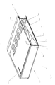
- FIG. 1 a luminaire 1 according to the invention is shown.
- the luminaire 1 consists of an optic 3 and a device carrier 2.
- the optics 3 is designed as a hollow body, which can radiate light on all sides.
- the device carrier 2 forms the back of the optics 3 and closes the hollow body.
- the device carrier 2 itself is not designed to emit light. From the equipment carrier 2 protrude two arms 5, 5 'in the interior of the hollow body. On both arms 5, 5 'is in each case a socket 6, 6 ' for the bulbs 3, 3 'mounted.
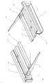
- FIGS. 3 and 4 protrude the two designed as unilaterally capped gas discharge lamps lamps with their free Ends through associated openings 7, 7 'in the boom 5, 5', which is opposite to the boom which carries the socket 6, 6 '.
- the arrangement of the sockets 6, 6 'on the arms 5, 5' inevitably results in that the lamps come to rest within the optics 3 when device carrier 2 and optics 3 are structurally combined.
- the equipment carrier has on its back a receiving space that can be used to accommodate operating devices, such as electronic ballasts or control units.
- FIG. 2 It can be seen that in the space between the bulbs 3, 3 'and the front of the optics 3, a reflector 9 is arranged.
- This reflector 9 is made of perforated plate and consists of an upper reflector wall 10 and a lower reflector wall 11.
- the two reflector walls 10, 11 run towards each other and abut each other in the area of the bulbs 3, 3 '.
- the two reflector elements In the area of the front side 9 of the optics 3, the two reflector elements have the greatest distance from one another.
- the reflector walls 10, 11 held by them formed on tabs 17, 17 ', which engage in a metal strip 13 in position.
- the metal strip 13 is preferably made of perforated plate and allows among other things special design effects.
- the device carrier 2 is substantially over its entire length in the area which is covered by the optics 3, coated with a head reflector 15.
- FIG. 2 Only in FIG. 2 the luminaire 1 according to the invention with a cover plate 16 is shown.
- This plate 16 which is made of translucent material and may have ventilation slots, is simply placed on the opening of the optics 3 to close them. This makes it possible at any time to get inside the lamp 1 to perform maintenance, such as a lamp replacement.
- a transparent element (not shown) may be arranged to prevent insects from reaching the area of the bottom plate 14. In fact, insects often die inside lights, and would appear as ugly dark spots on the bottom plate 14 without this transparent element firing the access.
- the cantilevers 5, 5 ' are replaced by a single cantilever formed of a plate-like element and extending over almost the entire length of the implement carrier. It is essential that this boom must be translucent, at least in some areas. This can be achieved by appropriate choice of material, such as perforated plate or translucent Plastic, or be achieved by providing appropriate openings or recesses.
Landscapes
- Engineering & Computer Science (AREA)
- General Engineering & Computer Science (AREA)
- Non-Portable Lighting Devices Or Systems Thereof (AREA)
Abstract
Description
- Die Erfindung betrifft eine Leuchte nach dem Oberbegriff des Anspruchs 1.
- Eine derartige Leuchte wird beispielsweise als Stehleuchte unter dem Markennamen Opura von der Anmelderin vermarktet. Sie zeichnet sich durch ihr Erscheinungsbild aus, dass wesentlich durch ihre Optik geprägt ist. Diese Optik ist aus einem Höhlkörper gebildet und allseitig Licht abstrahlend ausgeführt. Als Leuchtmittel kommen einseitig gesockelte Leuchtstofflampen zum Einsatz, deren Fassungen direkt am Geräteträger montiert sind. Im Geräteträger sind Komponenten zum Betrieb der Leuchtstofflampen, wie beispielsweise Klemmen und elektronische Vorschaltgeräte untergebracht.
- Aufgabe der Erfindung ist es, eine Leuchte der eingangs genannten Art so weiterzubilden, dass diese mit unterschiedlichen Leuchtmitteln verwendet werden kann. Hierbei ist darauf zu achten, dass die Funktionsweise der allseitig abstrahlenden Optik beibehalten wird.
- Die Aufgabe wird gelöst mit einer Leuchte mit den Merkmalen des Anspruchs 1. Vorteilhafte Weiterbildungen der Leuchte sind in den Unteransprüchen beschrieben.
- Kern der Erfindung ist es, dass am Geräteträger wenigstens ein Ausleger angebracht ist und dass auf dem Ausleger zumindest eine Fassung für ein Leuchtmittel angebracht ist. Außerdem ist der Ausleger zumindest in Teilbereichen lichtdurchlässig ausgeführt. Dadurch ist gewährleistet, dass das von dem Leuchtmittel erzeugte Licht in alle Bereiche des Hohlkörpers abgestrahlt wird und damit die gesamte Optik als leuchtender Körper wirkt, der allseitig Licht abgibt.
- In einer ersten bevorzugten Ausführungsform sind als Leuchtmittel zwei einseitig gesockelte Gasentladungslampen vorgesehen. Ferner sind zwei Ausleger beidseitig in den Endbereichen mit dem Geräteträger verbunden, wobei jeder der Ausleger eine Fassung trägt und sich bei jedem der Ausleger in dem Bereich, in dem beim einen Ausleger die Fassung angeordnet ist, beim anderen Ausleger ein lichtdurchlässiger Bereich, insbesondere eine Öffnung, befindet. Um die allseitige Lichtabstrahlung zu verbessern können die Gasentladungslampen mit ihren freien Enden durch diese öffnungen hindurchragen. Der sogenannte Coolspot, der kühlste Punkt der Gasentladungslampe, befindet sich bei diesem Lampentyp im Bereich des freien Endes. Da dieser Bereich vom Ausleger eng umschlossen ist, ist zumindest dann, wenn der Ausleger aus gut wärmeleitendem Material gefertigt ist, davon auszugehen, dass dieser Punkt auf einem gegenüber einer freistehenden Lampe auf niedrigem Temperaturniveau verbleibt und so der Wirkungsgrad der Lampe und damit der Leuchte optimiert ist.
- In einer zweiten Ausführungsform erstreckt sich der Ausleger im Wesentlichen über die gesamte Länge des Geräteträgers. Dieser Ausleger ist aus perforiertem Blech oder lichtdurchlässigem Kunststoff gefertigt, um nun auf diese Art die allseitige Lichtabstrahlung zu ermöglichen. Fassungen können damit auf dem Ausleger montiert werden. Somit können auch zweiseitig gesockelte Lampen für die erfindungsgemäße Leuchte verwendet werden.
- In einer dritten Ausführungsform sind als Leuchtmittel wiederum zwei einseitig gesockelte Gasentladungslampen vorgesehen, wobei der Ausleger sich im Wesentlichen über die gesamte Länge des Geräteträgers erstreckt. Im Bereich über dem sich jeweils ein freies Ende eines der Leuchtmittel befindet ist ein lichtdurchlässiger Bereich, insbesondere eine Öffnung, vorhanden. Eine derartige Öffnung kann auch durch eine Freistanzung oder Freistellung gebildet sein. Insbesondere der Ausleger für die zweite und dritte Ausführungsform kann teillichtdurchlässig und reflektierend ausgebildet sein, um die Aufteilung zwischen Direkt und Indirektanteil des Lichts festzulegen. Unter Direktanteil ist jener Teil des Lichtes zu verstehen, der ausgehend von der Leuchte direkt auf eine normalerweise unter der Leuchte befindliche und zu beleuchtende Fläche abgestrahlt wird, während unter Indirektanteil jener Teil des Lichtes zu verstehen ist, der ausgehend von der Leuchte üblicherweise an eine Wand oder Decke über der Leuchte abgestrahlt wird und so der Aufhellung des zu beleuchtenden Raumes dient.
- Bevorzugt ist im Freiraum zwischen Leuchtmittel und Frontseite der Optik ein teillichtdurchlässiger Reflektor angeordnet. Dieser Reflektor kann aus zwei Reflektorwänden gebildet sein, welche so angeordnet sind, dass diese in spitzem Winkel aufeinander zulaufen, wobei die Stossstelle im Bereich des Leuchtmittels und der größte Abstand zwischen den beiden Reflektorwänden im Bereich der Frontseite ist. Der bzw. die Ausleger können den Reflektor tragen und so im Hohlkörper fixieren.
- Vorzugsweise werden in der erfindungsgemäßen Leuchte als Leuchtmittel eine, insbesondere zwei, Leuchtstofflampen des Typs TC-L, 28 Watt verwendet. Werden Lampen in diesem Leistungsbereich eingesetzt, kann die Aufteilung zwischen Direkt und Indirektanteil beispielsweise durch die Wahl der Reflexionseigenschaften und des Grades der Lichtdurchlässigkeit so eingestellt werden, dass die Aufteilung etwa 35 % für den Direktanteil und 65 % für den Indirektanteil beträgt. Hierbei ist zu beachten, dass die einschlägigen Normen, welche unter anderem Vorgaben zur Blendbegrenzung vorsehen, eingehalten werden. Im konkreten Fall wird als Reflektormaterial ein Aluminiumblech mit der Markenbezeichnung Miro 7 mit einem Lochanteil von mindestens 22% verwendet. Neben der erzeugten Lichtleistung durch die Lampen und die genannten Reflektoreigenschaften ist für die Einhaltung der einschlägigen Normen auch wesentlich, dass das Licht auch über die Frontseite und Seitenwände der Optik abgestrahlt werden. Insgesamt ermöglicht diese Bauweise in Verbindung mit den zuvor genannten bzw. vergleichbaren Leuchtstofflampen eine normkonforme Leuchte für anspruchsvolle Beleuchtungsaufgaben, wie beispielsweise die Beleuchtung von Bildschirmarbeitsplätze, zu schaffen, die gegenüber dem Stand der Technik einen niedrigeren Energieverbrauch aufweist.
- Einerseits um die lichttechnischen Eigenschaften der Optik zu beeinflussen und andererseits wegen eines ansprechenden gestalterischen Effekts, ist im Inneren der Optik entlang der Seitenwände und der Fronseite ein perforiertes, vorzugsweise als Lochblech ausgeführtes Metallband angeordnet.
- Die Optik selbst ist als Hohlkörper mit Frontseite und Seitenwände ausgeführt. Die Rückseite des Hohlkörpers wird mit dem Geräteträger verschlossen. Vorzugsweise sind die Frontseite und die Seitenwände einstückig aus einer Mikroprismenplatte gefertigt. Die Ecken zwischen Frontseite und Seitenwänden können in diesem Fall verrundet sein und sind durch Warmverformen des Kunststoffes gebildet. Die Bodenplatte der Abdeckung ist aus einer Mikropyramidenplatte oder in Sandwichbauweise aus einer glasklaren Bodenplatte mit darüber angeordneter Mikropyramidenplatte hergestellt, wobei die Frontseite und die Seitenwände mit der Bodenplatte verklebt sind. Auf der Oberseite der Optik kann eine lichtdurchlässige Abdeckplatte aufgelegt werden, um das Eindringen von Staub in den Hohlkörper zu vermeiden oder zumindest zu verringern. Der Vollständigkeit halber sei erwähnt, dass anstelle der Mikroprismenplatte bzw. der Mikropyramidenplatte, die sich dadurch auszeichnen, das die lichttechnisch wirksame Struktur in die Oberflächen der Platten eingearbeitet sind, auch glasklare Platten verwendet werden können und die lichttechnischen Eigenschaften durch Einlegen von zusätzlichen Elementen wie Folien oder Platten mit entsprechenden Strukturen erreicht werden können. Ebenfalls ist es möglich andere Strukturen wie beispielsweise Mikrolinsen oder dergleichen anstelle von Mikroprismen oder Mikropyramiden zu verwenden.
- Die erfindungsgemäße Leuchte kann mittels eines Montageblechs in bekannter Art und Weise an einer Wand Decke montiert werden und so beispielsweise als Wandleuchte eingesetzt werden. Ebenfalls möglich ist die Verwendung der Leuchte in Verbindung mit einem Steher.
- Damit kann eine Stehleuchte gebildet werden. Andere Einsatzmöglichkeiten als Decken oder Pendelleuchte sind ebenfalls denkbar.
- Nachfolgend wird die Erfindung anhand der beiliegenden Zeichnungen näher erläutert. Es zeigen:
-
Figur 1 eine perspektivische Ansicht einer erfindungsgemäßen Leuchte, -
Figur 2 einen Schnitt durch eine erfindungsgemäße Leuchte gemäßeFigur 1 , -
Figur 3 eine erste perspektivische Ansicht von Teilen einer erfindungsgemäßen Leuchte gemäßFigur 1 und -
Figur 4 eine zweite perspektivische Ansicht von Teilen einer erfindungsgemäßen Leuchte gemäßFigur 1 . - In
Figur 1 ist eine erfindungsgemäße Leuchte 1 dargestellt. Die Leuchte 1 besteht aus einer Optik 3 und einem Geräteträger 2. Die Optik 3 ist als Höhlkörper ausgebildet, welcher allseitig Licht abstrahlen kann. Der Geräteträger 2 bildet die Rückseite der Optik 3 und verschließt den Hohlkörper. Der Geräteträger 2 selbst ist nicht Licht abstrahlend ausgeführt. Vom Geräteträger 2 ragen zwei Ausleger 5, 5' in das Innere des Höhlkörpers. Auf beiden Auslegern 5, 5' ist jeweils eine Fassung 6, 6' für die Leuchtmittel 3, 3' montiert. - Wie insbesondere aus den
Figuren 3 und 4 erkennbar ist, ragen die beiden als einseitig gesockelte Gasentladungslampen ausgeführten Lampen mit ihren freien Enden durch zugeordnete Öffnungen 7, 7' in dem Ausleger 5, 5', welcher dem Ausleger, der die Fassung 6, 6' trägt, gegenüber liegt. Durch die Anordnung der Fassungen 6, 6' auf den Auslegern 5, 5' ergibt sich zwangsläufig, dass die Lampen innerhalb der Optik 3 zu liegen kommen, wenn Geräteträger 2 und Optik 3 baulich vereinigt werden. AusFigur 4 ist außerdem zu entnehmen, dass der Geräteträger an seiner Rückseite einen Aufnahmeraum aufweist, der zur Unterbringung von Betriebsgeräten, wie beispielsweise elektronische Vorschaltgeräte oder Steuergeräte, genutzt werden kann. - Aus
Figur 2 ist ersichtlich, dass im Freiraum zwischen den Leuchtmitteln 3, 3' und der Frontseite der Optik 3 ein Reflektor 9 angeordnet ist. Dieser Reflektor 9 ist aus Lochblech hergestellt und besteht aus einer oberen Reflektorwand 10 und einer unteren Reflektorwand 11. Die beiden Reflektorwände 10, 11 laufen aufeinander zu und stoßen im Bereich der Leuchtmittel 3, 3' aneinander. Im Bereich der Frontseite 9 der Optik 3 weisen die beiden Reflektorelemente den größten Abstand zueinander auf. Die beiden keilförmig geformten Ausleger 5, 5' tragen den Reflektor 9 dadurch, dass sie mit ihren spitzen Enden nicht dargestellte Ausnehmungen im Reflektor 9 untergreifen. Ferner werden die Reflektorwände 10, 11 durch an sie angeformte Laschen 17, 17', welche in ein Metallband 13 eingreifen, in Position gehalten. Das Metallband 13 ist vorzugsweise aus Lochblech gefertigt und ermöglicht unter anderem besondere gestalterische Effekte. - Zur Verbesserung der lichttechnischen Eigenschaften der gesamten Leuchte 1 ist der Geräteträger 2 im Wesentlichen über seine gesamte Länge im Bereich, welcher von der Optik 3 überdeckt ist, mit einem Kopfreflektor 15 überzogen.
- Nur in
Figur 2 ist die erfindungsgemäße Leuchte 1 mit einer Abdeckplatte 16 gezeigt. Diese Platte 16, welche aus lichtdurchlässigem Material gefertigt ist, und Belüftungsschlitze aufweisen kann, wird einfach auf die Öffnung der Optik 3 gelegt, um diese zu verschließen. Dadurch ist es jederzeit möglich ins Innere der Leuchte 1 zu gelangen, um Wartungsarbeiten, wie beispielsweise einen Lampentausch, durchzuführen. - Unterhalb der Leuchtmittel 3, 3', zwischen dem Reflektor 9 und dem Kopfreflektor 15, kann ein (nicht dargestelltes) transparentes Element angeordnet werden, um zu verhindern, dass Insekten in den Bereich der Bodenplatte 14 gelangen können. Insekten verenden nämlich häufig im Inneren von Leuchten und würden ohne diese transparentes Element, welches den Zugang verschießt, sich als unschöne dunkle Flecken auf der Bodenplatte 14 abzeichnen.
- Die einleitend erwähnte, zweite und dritte Ausführungsform der Erfindung sind zeichnerisch nicht dargestellt, weil die Veränderungen nur im Bereich der Gestaltung des Auslegers zu sehen sind. Im Wesentlichen werden die Ausleger 5, 5' durch einen einzigen Ausleger ersetzt, der aus einem plattenartigem Element gebildet ist und sich über nahezu die gesamte Länge des Geräteträgers erstreckt. Wesentlich hierbei ist, dass auch dieser Ausleger zumindest in Teilbereichen lichtdurchlässig sein muss. Dies kann durch entsprechende Materialwahl, möglich wären beispielsweise Lochblech oder lichtdurchlässiger Kunststoff, oder durch Vorsehen entsprechender Öffnungen oder Ausnehmungen erreicht werden.
-
- 1
- Leuchte
- 2
- Geräteträger
- 3, 3'
- Leuchtmittel
- 4
- Optik
- 5, 5'
- Ausleger
- 6, 6'
- Fassung
- 7, 7'
- Öffnung
- 8
- Frontseite
- 9
- Reflektor
- 10
- Reflektorwand
- 11
- Reflektorwand
- 12, 12'
- Seitenwand
- 13
- Metallband
- 14
- Bodenplatte
- 15
- Kopfreflektor
- 16
- Abdeckplatte
- 17, 17'
- Laschen
Claims (15)
- Leuchte (1) aufweisend- einen Geräteträger (2) zur Aufnahme für Komponenten zum Betrieb eines Leuchtmittels (3, 3'),- eine aus einem Höhlkörper gebildete und allseitig Licht abstrahlende Optik (4),dadurch gekennzeichnet,
dass am Geräteträger (2) ein Ausleger (5, 5') angebracht ist,
dass auf dem Ausleger (5, 5') eine Fassung (6, 6') für das Leuchtmittel (3, 3') angebracht ist,
dass der Ausleger (5, 5') zumindest in Teilbereichen lichtdurchlässig ausgeführt ist. - Leuchte nach Anspruch 1,
dadurch gekennzeichnet,
dass als Leuchtmittel (3, 3') zwei einseitig gesockelte Gasentladungslampen vorgesehen sind,
dass zwei Ausleger (5, 5') vorgesehen sind die beidseitig in den Endbereichen mit dem Geräteträger (2) verbunden sind und
dass jeder der Ausleger (5, 5') eine Fassung (6, 6') trägt. - Leuchte nach Anspruch 2,
dadurch gekennzeichnet,
dass bei jedem der Ausleger (5, 5'), in dem Bereich, in dem beim einen Ausleger (5, 5') die Fassung (6, 6') angeordnet ist, sich beim anderen Ausleger (5, 5') eine lichtdurchlässiger Bereich, insbesondere eine Öffnung (7, 7'), befindet. - Leuchte nach Anspruch 2 oder 3,
dadurch gekennzeichnet,
dass die Gasentladungslampen mit ihren freien Enden in die Öffnungen (7, 7') hindurchragen. - Leuchte nach Anspruch 1,
dadurch gekennzeichnet,
dass der Ausleger sich im Wesentlichen über die gesamte Länge des Geräteträgers (2) erstreckt und aus perforiertem Blech oder lichtdurchlässigem Kunststoff gefertigt ist. - Leuchte nach Anspruch 1,
dadurch gekennzeichnet,
dass als Leuchtmittel (3, 3') zwei einseitig gesockelte Gasentladungslampen vorgesehen sind,
dass der Ausleger sich im Wesentlichen über die gesamte Länge des Geräteträgers (2) erstreckt und dass sich in den Bereichen über dem sich jeweils ein freies Ende eines der Leuchtmittel (3, 3') befindet ein lichtdurchlässiger Bereich, insbesondere eine Öffnung, vorhanden ist. - Leuchte nach Anspruch 5 oder 6,
dadurch gekennzeichnet,
dass der Ausleger als teillichtdurchlässig und reflektierend ausgebildet ist und die Aufteilung zwischen Direkt und Indirektanteil des Lichts bestimmt. - Leuchte nach einem der vorigen Ansprüche,
dadurch gekennzeichnet,
dass im Freiraum zwischen Leuchtmittel (3, 3') und Frontseite (8) der Optik (4) ein teillichtdurchlässiger Reflektor (9) angeordnet ist und die Aufteilung zwischen Direkt und Indirektanteil des Lichts bestimmt. - Leuchte nach Anspruch 8,
dadurch gekennzeichnet,
dass der Reflektor (9) aus zwei Reflektorwänden (10, 11) gebildet ist, welche so angeordnet sind, dass diese in spitzem Winkel aufeinander zulaufen, wobei die Stossstelle im Bereich des Leuchtmittels (3, 3') und der größte Abstand zwischen den beiden Reflektorwänden (10, 11) im Bereich der Frontseite (9) ist. - Leuchte nach einem der vorigen Ansprüche,
dadurch gekennzeichnet,
dass der Ausleger (5, 5') den Reflektor trägt. - Leuchte nach einem der vorigen Ansprüche,
dadurch gekennzeichnet,
dass als Leuchtmittel (3, 3') eine, insbesondere zwei Leuchtstofflampen des Typs TC-L, 28 Watt verwendet werden. - Leuchte nach einem der vorigen Ansprüche, insbesondere dem Anspruch 11,
dadurch gekennzeichnet,
dass die Aufteilung zwischen Direkt und Indirektanteil etwa 35 % für den Direktanteil zu 65 % für den Indirektanteil beträgt. - Leuchte nach einem der vorigen Ansprüche,
dadurch gekennzeichnet,
dass im Inneren der Optik entlang der Seitenwände (12, 12') und der Fronseite (8) ein perforiertes Metallband (13), vorzugsweise ein Lochblech, angeordnet ist. - Leuchte nach einem der vorigen Ansprüche,
dadurch gekennzeichnet,
dass die Frontseite (8) und die Seitenwände (12, 12') einstückig aus einer Mikroprismenplatte gefertigt sind und
dass die Bodenplatte (14) der Optik (4) aus einer Mikropyramidenplatte gefertigt ist, wobei die Frontseite (8) und die Seitenwände (12, 12') mit der Bodenplatte (14) verklebt sind. - Leuchte nach einem der vorigen Ansprüche 1-12,
dadurch gekennzeichnet,
dass die Frontseite (8) und die Seitenwände (12, 12') einstückig aus einer Mikroprismenplatte gefertigt sind und
dass die Bodenplatte (14) der Optik (4) aus glasklarem Kunststoff gefertigt und eine Mikropyramidenplatte über der Bodenplatte angeordnet ist, wobei die Frontseite (8) und die Seitenwände (12, 12') mit der Bodenplatte (14) verklebt sind.
Applications Claiming Priority (1)
| Application Number | Priority Date | Filing Date | Title |
|---|---|---|---|
| AT0064908U AT11271U1 (de) | 2008-11-13 | 2008-11-13 | Leuchte |
Publications (2)
| Publication Number | Publication Date |
|---|---|
| EP2194314A1 true EP2194314A1 (de) | 2010-06-09 |
| EP2194314B1 EP2194314B1 (de) | 2018-07-04 |
Family
ID=42102276
Family Applications (1)
| Application Number | Title | Priority Date | Filing Date |
|---|---|---|---|
| EP09014108.6A Not-in-force EP2194314B1 (de) | 2008-11-13 | 2009-11-11 | Leuchte |
Country Status (2)
| Country | Link |
|---|---|
| EP (1) | EP2194314B1 (de) |
| AT (1) | AT11271U1 (de) |
Citations (5)
| Publication number | Priority date | Publication date | Assignee | Title |
|---|---|---|---|---|
| US4680677A (en) * | 1985-03-18 | 1987-07-14 | Ross John J | Freestanding luminaire having floor-supported frame integrated with light fixture |
| US5217301A (en) * | 1991-06-11 | 1993-06-08 | Peerless Lighting Corporation | Lighting fixture having an unobtrusive surface switch |
| DE202004003955U1 (de) * | 2004-03-13 | 2004-05-13 | Spectral Gesellschaft für Lichttechnik mbH | Stehleuchte |
| DE102006006590A1 (de) * | 2006-01-16 | 2007-07-26 | Siteco Beleuchtungstechnik Gmbh | Leuchte mit einem Komposit-Trägerelement |
| DE102006045745A1 (de) * | 2006-09-27 | 2008-04-03 | Zumtobel Lighting Gmbh | Stehleuchte |
-
2008
- 2008-11-13 AT AT0064908U patent/AT11271U1/de not_active IP Right Cessation
-
2009
- 2009-11-11 EP EP09014108.6A patent/EP2194314B1/de not_active Not-in-force
Patent Citations (5)
| Publication number | Priority date | Publication date | Assignee | Title |
|---|---|---|---|---|
| US4680677A (en) * | 1985-03-18 | 1987-07-14 | Ross John J | Freestanding luminaire having floor-supported frame integrated with light fixture |
| US5217301A (en) * | 1991-06-11 | 1993-06-08 | Peerless Lighting Corporation | Lighting fixture having an unobtrusive surface switch |
| DE202004003955U1 (de) * | 2004-03-13 | 2004-05-13 | Spectral Gesellschaft für Lichttechnik mbH | Stehleuchte |
| DE102006006590A1 (de) * | 2006-01-16 | 2007-07-26 | Siteco Beleuchtungstechnik Gmbh | Leuchte mit einem Komposit-Trägerelement |
| DE102006045745A1 (de) * | 2006-09-27 | 2008-04-03 | Zumtobel Lighting Gmbh | Stehleuchte |
Also Published As
| Publication number | Publication date |
|---|---|
| EP2194314B1 (de) | 2018-07-04 |
| AT11271U1 (de) | 2010-07-15 |
Similar Documents
| Publication | Publication Date | Title |
|---|---|---|
| EP2151899B1 (de) | Lichtbandsystem | |
| EP1979668B1 (de) | Leuchte mit einem kastenförmigen leuchtengehäuse und einem lichtaustrittselement | |
| EP1043542A2 (de) | Beleuchtungsanordnung zur Anbringung an der Decke oder einer Wand eines Raumes | |
| DE202009003785U1 (de) | LED-Leuchtröhrenanordnung | |
| DE202009017522U1 (de) | LED-Einbauleuchte mit Kühlkörper | |
| DE102011051038A1 (de) | LED Beleuchtungsanordnung | |
| EP1845396A1 (de) | Leuchte mit wenigstens einer lichtdurchlässigen Abdeckung | |
| CH709009A1 (de) | Befestigung einer Leiterplatte und einer Optik einer Leuchte. | |
| EP2994693B1 (de) | Abdeckungselement für flächenleuchte | |
| DE19923224A1 (de) | Beleuchtungsanordnung zur Anbringung an der Decke oder einer Wand eines Raumes | |
| EP3090292B1 (de) | Leuchtenanordnung sowie leuchte | |
| DE102006016218A1 (de) | Leuchte, insbesondere Raumleuchte | |
| DE202009017585U1 (de) | LED-Einbauleuchte mit Reflexionsplatte | |
| EP1365189B1 (de) | Leuchte | |
| AT509179B1 (de) | Schwenkbare led einbauleuchte mit geringer einbauhöhe | |
| EP2194314B1 (de) | Leuchte | |
| EP2175188B1 (de) | Leuchte | |
| DE102010063750B4 (de) | Dunstabzugshaube mit Leuchtmodul | |
| DE202007013177U1 (de) | Leuchte | |
| AT14025U1 (de) | Leuchtengehäuse mit Lochkaschierung | |
| EP2711622B1 (de) | Leuchte mit Berührschutz | |
| DE202007012601U1 (de) | Pendelleuchte | |
| DE10344066B4 (de) | Leuchte mit einem Reflektor und einer von dem Reflektor beabstandeten Lichtaustrittsscheibe | |
| DE102011101610B3 (de) | Leuchte | |
| DE202018105443U1 (de) | Leuchtmitteleinsatzmodul |
Legal Events
| Date | Code | Title | Description |
|---|---|---|---|
| PUAI | Public reference made under article 153(3) epc to a published international application that has entered the european phase |
Free format text: ORIGINAL CODE: 0009012 |
|
| AK | Designated contracting states |
Kind code of ref document: A1 Designated state(s): AT BE BG CH CY CZ DE DK EE ES FI FR GB GR HR HU IE IS IT LI LT LU LV MC MK MT NL NO PL PT RO SE SI SK SM TR |
|
| AX | Request for extension of the european patent |
Extension state: AL BA RS |
|
| 17P | Request for examination filed |
Effective date: 20101209 |
|
| GRAP | Despatch of communication of intention to grant a patent |
Free format text: ORIGINAL CODE: EPIDOSNIGR1 |
|
| RIC1 | Information provided on ipc code assigned before grant |
Ipc: F21S 6/00 20060101ALI20171006BHEP Ipc: F21V 5/02 20060101ALN20171006BHEP Ipc: F21Y 103/00 20160101ALI20171006BHEP Ipc: F21V 5/00 20150101ALN20171006BHEP Ipc: F21V 15/01 20060101ALI20171006BHEP Ipc: F21V 21/10 20060101AFI20171006BHEP |
|
| INTG | Intention to grant announced |
Effective date: 20171025 |
|
| GRAS | Grant fee paid |
Free format text: ORIGINAL CODE: EPIDOSNIGR3 |
|
| GRAA | (expected) grant |
Free format text: ORIGINAL CODE: 0009210 |
|
| AK | Designated contracting states |
Kind code of ref document: B1 Designated state(s): AT BE BG CH CY CZ DE DK EE ES FI FR GB GR HR HU IE IS IT LI LT LU LV MC MK MT NL NO PL PT RO SE SI SK SM TR |
|
| REG | Reference to a national code |
Ref country code: GB Ref legal event code: FG4D Free format text: NOT ENGLISH |
|
| REG | Reference to a national code |
Ref country code: CH Ref legal event code: EP |
|
| REG | Reference to a national code |
Ref country code: AT Ref legal event code: REF Ref document number: 1014911 Country of ref document: AT Kind code of ref document: T Effective date: 20180715 |
|
| REG | Reference to a national code |
Ref country code: IE Ref legal event code: FG4D Free format text: LANGUAGE OF EP DOCUMENT: GERMAN |
|
| REG | Reference to a national code |
Ref country code: DE Ref legal event code: R096 Ref document number: 502009015060 Country of ref document: DE |
|
| REG | Reference to a national code |
Ref country code: DE Ref legal event code: R084 Ref document number: 502009015060 Country of ref document: DE |
|
| REG | Reference to a national code |
Ref country code: NL Ref legal event code: MP Effective date: 20180704 |
|
| REG | Reference to a national code |
Ref country code: LT Ref legal event code: MG4D |
|
| PG25 | Lapsed in a contracting state [announced via postgrant information from national office to epo] |
Ref country code: NL Free format text: LAPSE BECAUSE OF FAILURE TO SUBMIT A TRANSLATION OF THE DESCRIPTION OR TO PAY THE FEE WITHIN THE PRESCRIBED TIME-LIMIT Effective date: 20180704 |
|
| PG25 | Lapsed in a contracting state [announced via postgrant information from national office to epo] |
Ref country code: PL Free format text: LAPSE BECAUSE OF FAILURE TO SUBMIT A TRANSLATION OF THE DESCRIPTION OR TO PAY THE FEE WITHIN THE PRESCRIBED TIME-LIMIT Effective date: 20180704 Ref country code: IS Free format text: LAPSE BECAUSE OF FAILURE TO SUBMIT A TRANSLATION OF THE DESCRIPTION OR TO PAY THE FEE WITHIN THE PRESCRIBED TIME-LIMIT Effective date: 20181104 Ref country code: SE Free format text: LAPSE BECAUSE OF FAILURE TO SUBMIT A TRANSLATION OF THE DESCRIPTION OR TO PAY THE FEE WITHIN THE PRESCRIBED TIME-LIMIT Effective date: 20180704 Ref country code: GR Free format text: LAPSE BECAUSE OF FAILURE TO SUBMIT A TRANSLATION OF THE DESCRIPTION OR TO PAY THE FEE WITHIN THE PRESCRIBED TIME-LIMIT Effective date: 20181005 Ref country code: FI Free format text: LAPSE BECAUSE OF FAILURE TO SUBMIT A TRANSLATION OF THE DESCRIPTION OR TO PAY THE FEE WITHIN THE PRESCRIBED TIME-LIMIT Effective date: 20180704 Ref country code: NO Free format text: LAPSE BECAUSE OF FAILURE TO SUBMIT A TRANSLATION OF THE DESCRIPTION OR TO PAY THE FEE WITHIN THE PRESCRIBED TIME-LIMIT Effective date: 20181004 Ref country code: CZ Free format text: LAPSE BECAUSE OF FAILURE TO SUBMIT A TRANSLATION OF THE DESCRIPTION OR TO PAY THE FEE WITHIN THE PRESCRIBED TIME-LIMIT Effective date: 20180704 Ref country code: BG Free format text: LAPSE BECAUSE OF FAILURE TO SUBMIT A TRANSLATION OF THE DESCRIPTION OR TO PAY THE FEE WITHIN THE PRESCRIBED TIME-LIMIT Effective date: 20181004 Ref country code: LT Free format text: LAPSE BECAUSE OF FAILURE TO SUBMIT A TRANSLATION OF THE DESCRIPTION OR TO PAY THE FEE WITHIN THE PRESCRIBED TIME-LIMIT Effective date: 20180704 |
|
| PG25 | Lapsed in a contracting state [announced via postgrant information from national office to epo] |
Ref country code: HR Free format text: LAPSE BECAUSE OF FAILURE TO SUBMIT A TRANSLATION OF THE DESCRIPTION OR TO PAY THE FEE WITHIN THE PRESCRIBED TIME-LIMIT Effective date: 20180704 Ref country code: LV Free format text: LAPSE BECAUSE OF FAILURE TO SUBMIT A TRANSLATION OF THE DESCRIPTION OR TO PAY THE FEE WITHIN THE PRESCRIBED TIME-LIMIT Effective date: 20180704 Ref country code: ES Free format text: LAPSE BECAUSE OF FAILURE TO SUBMIT A TRANSLATION OF THE DESCRIPTION OR TO PAY THE FEE WITHIN THE PRESCRIBED TIME-LIMIT Effective date: 20180704 |
|
| REG | Reference to a national code |
Ref country code: DE Ref legal event code: R097 Ref document number: 502009015060 Country of ref document: DE |
|
| PG25 | Lapsed in a contracting state [announced via postgrant information from national office to epo] |
Ref country code: RO Free format text: LAPSE BECAUSE OF FAILURE TO SUBMIT A TRANSLATION OF THE DESCRIPTION OR TO PAY THE FEE WITHIN THE PRESCRIBED TIME-LIMIT Effective date: 20180704 Ref country code: EE Free format text: LAPSE BECAUSE OF FAILURE TO SUBMIT A TRANSLATION OF THE DESCRIPTION OR TO PAY THE FEE WITHIN THE PRESCRIBED TIME-LIMIT Effective date: 20180704 Ref country code: IT Free format text: LAPSE BECAUSE OF FAILURE TO SUBMIT A TRANSLATION OF THE DESCRIPTION OR TO PAY THE FEE WITHIN THE PRESCRIBED TIME-LIMIT Effective date: 20180704 |
|
| PGFP | Annual fee paid to national office [announced via postgrant information from national office to epo] |
Ref country code: DE Payment date: 20190131 Year of fee payment: 10 |
|
| PLBE | No opposition filed within time limit |
Free format text: ORIGINAL CODE: 0009261 |
|
| STAA | Information on the status of an ep patent application or granted ep patent |
Free format text: STATUS: NO OPPOSITION FILED WITHIN TIME LIMIT |
|
| PG25 | Lapsed in a contracting state [announced via postgrant information from national office to epo] |
Ref country code: SM Free format text: LAPSE BECAUSE OF FAILURE TO SUBMIT A TRANSLATION OF THE DESCRIPTION OR TO PAY THE FEE WITHIN THE PRESCRIBED TIME-LIMIT Effective date: 20180704 Ref country code: DK Free format text: LAPSE BECAUSE OF FAILURE TO SUBMIT A TRANSLATION OF THE DESCRIPTION OR TO PAY THE FEE WITHIN THE PRESCRIBED TIME-LIMIT Effective date: 20180704 Ref country code: SK Free format text: LAPSE BECAUSE OF FAILURE TO SUBMIT A TRANSLATION OF THE DESCRIPTION OR TO PAY THE FEE WITHIN THE PRESCRIBED TIME-LIMIT Effective date: 20180704 |
|
| 26N | No opposition filed |
Effective date: 20190405 |
|
| REG | Reference to a national code |
Ref country code: CH Ref legal event code: PL |
|
| GBPC | Gb: european patent ceased through non-payment of renewal fee |
Effective date: 20181111 |
|
| PG25 | Lapsed in a contracting state [announced via postgrant information from national office to epo] |
Ref country code: MC Free format text: LAPSE BECAUSE OF FAILURE TO SUBMIT A TRANSLATION OF THE DESCRIPTION OR TO PAY THE FEE WITHIN THE PRESCRIBED TIME-LIMIT Effective date: 20180704 Ref country code: LU Free format text: LAPSE BECAUSE OF NON-PAYMENT OF DUE FEES Effective date: 20181111 |
|
| REG | Reference to a national code |
Ref country code: BE Ref legal event code: MM Effective date: 20181130 |
|
| REG | Reference to a national code |
Ref country code: IE Ref legal event code: MM4A |
|
| PG25 | Lapsed in a contracting state [announced via postgrant information from national office to epo] |
Ref country code: CH Free format text: LAPSE BECAUSE OF NON-PAYMENT OF DUE FEES Effective date: 20181130 Ref country code: LI Free format text: LAPSE BECAUSE OF NON-PAYMENT OF DUE FEES Effective date: 20181130 Ref country code: SI Free format text: LAPSE BECAUSE OF FAILURE TO SUBMIT A TRANSLATION OF THE DESCRIPTION OR TO PAY THE FEE WITHIN THE PRESCRIBED TIME-LIMIT Effective date: 20180704 |
|
| PG25 | Lapsed in a contracting state [announced via postgrant information from national office to epo] |
Ref country code: FR Free format text: LAPSE BECAUSE OF NON-PAYMENT OF DUE FEES Effective date: 20181130 Ref country code: IE Free format text: LAPSE BECAUSE OF NON-PAYMENT OF DUE FEES Effective date: 20181111 |
|
| PG25 | Lapsed in a contracting state [announced via postgrant information from national office to epo] |
Ref country code: BE Free format text: LAPSE BECAUSE OF NON-PAYMENT OF DUE FEES Effective date: 20181130 |
|
| PG25 | Lapsed in a contracting state [announced via postgrant information from national office to epo] |
Ref country code: GB Free format text: LAPSE BECAUSE OF NON-PAYMENT OF DUE FEES Effective date: 20181111 |
|
| REG | Reference to a national code |
Ref country code: AT Ref legal event code: MM01 Ref document number: 1014911 Country of ref document: AT Kind code of ref document: T Effective date: 20181111 |
|
| PG25 | Lapsed in a contracting state [announced via postgrant information from national office to epo] |
Ref country code: MT Free format text: LAPSE BECAUSE OF FAILURE TO SUBMIT A TRANSLATION OF THE DESCRIPTION OR TO PAY THE FEE WITHIN THE PRESCRIBED TIME-LIMIT Effective date: 20180704 Ref country code: AT Free format text: LAPSE BECAUSE OF NON-PAYMENT OF DUE FEES Effective date: 20181111 |
|
| PG25 | Lapsed in a contracting state [announced via postgrant information from national office to epo] |
Ref country code: TR Free format text: LAPSE BECAUSE OF FAILURE TO SUBMIT A TRANSLATION OF THE DESCRIPTION OR TO PAY THE FEE WITHIN THE PRESCRIBED TIME-LIMIT Effective date: 20180704 |
|
| PG25 | Lapsed in a contracting state [announced via postgrant information from national office to epo] |
Ref country code: PT Free format text: LAPSE BECAUSE OF FAILURE TO SUBMIT A TRANSLATION OF THE DESCRIPTION OR TO PAY THE FEE WITHIN THE PRESCRIBED TIME-LIMIT Effective date: 20180704 |
|
| REG | Reference to a national code |
Ref country code: DE Ref legal event code: R119 Ref document number: 502009015060 Country of ref document: DE |
|
| PG25 | Lapsed in a contracting state [announced via postgrant information from national office to epo] |
Ref country code: HU Free format text: LAPSE BECAUSE OF FAILURE TO SUBMIT A TRANSLATION OF THE DESCRIPTION OR TO PAY THE FEE WITHIN THE PRESCRIBED TIME-LIMIT; INVALID AB INITIO Effective date: 20091111 Ref country code: CY Free format text: LAPSE BECAUSE OF FAILURE TO SUBMIT A TRANSLATION OF THE DESCRIPTION OR TO PAY THE FEE WITHIN THE PRESCRIBED TIME-LIMIT Effective date: 20180704 Ref country code: MK Free format text: LAPSE BECAUSE OF NON-PAYMENT OF DUE FEES Effective date: 20180704 |
|
| PG25 | Lapsed in a contracting state [announced via postgrant information from national office to epo] |
Ref country code: DE Free format text: LAPSE BECAUSE OF NON-PAYMENT OF DUE FEES Effective date: 20200603 |