EP2193741B1 - Haushaltgerät mit Wärmespeicher und Wärmekopplungstank - Google Patents
Haushaltgerät mit Wärmespeicher und Wärmekopplungstank Download PDFInfo
- Publication number
- EP2193741B1 EP2193741B1 EP10002683.0A EP10002683A EP2193741B1 EP 2193741 B1 EP2193741 B1 EP 2193741B1 EP 10002683 A EP10002683 A EP 10002683A EP 2193741 B1 EP2193741 B1 EP 2193741B1
- Authority
- EP
- European Patent Office
- Prior art keywords
- heat
- household appliance
- tank
- coupling tank
- coupling
- Prior art date
- Legal status (The legal status is an assumption and is not a legal conclusion. Google has not performed a legal analysis and makes no representation as to the accuracy of the status listed.)
- Active
Links
- 238000010168 coupling process Methods 0.000 claims description 104
- 238000005859 coupling reaction Methods 0.000 claims description 104
- 230000008878 coupling Effects 0.000 claims description 101
- 238000000034 method Methods 0.000 claims description 85
- 230000008569 process Effects 0.000 claims description 82
- XLYOFNOQVPJJNP-UHFFFAOYSA-N water Substances O XLYOFNOQVPJJNP-UHFFFAOYSA-N 0.000 claims description 49
- 239000012530 fluid Substances 0.000 claims description 23
- 239000003999 initiator Substances 0.000 claims description 13
- 239000013505 freshwater Substances 0.000 claims description 12
- 239000007788 liquid Substances 0.000 claims description 10
- 230000007704 transition Effects 0.000 claims description 10
- 238000005406 washing Methods 0.000 claims description 10
- 230000008014 freezing Effects 0.000 claims description 7
- 238000007710 freezing Methods 0.000 claims description 7
- 239000002351 wastewater Substances 0.000 claims description 6
- 238000001035 drying Methods 0.000 claims description 5
- 238000007599 discharging Methods 0.000 claims description 4
- 238000005338 heat storage Methods 0.000 description 44
- 239000012071 phase Substances 0.000 description 43
- 101150114468 TUB1 gene Proteins 0.000 description 29
- 239000000463 material Substances 0.000 description 7
- 239000000945 filler Substances 0.000 description 5
- 238000004140 cleaning Methods 0.000 description 3
- 238000010411 cooking Methods 0.000 description 3
- 238000001816 cooling Methods 0.000 description 3
- 238000010438 heat treatment Methods 0.000 description 3
- IIPYXGDZVMZOAP-UHFFFAOYSA-N lithium nitrate Chemical compound [Li+].[O-][N+]([O-])=O IIPYXGDZVMZOAP-UHFFFAOYSA-N 0.000 description 3
- 230000008018 melting Effects 0.000 description 3
- 238000002844 melting Methods 0.000 description 3
- 238000010926 purge Methods 0.000 description 3
- 239000007921 spray Substances 0.000 description 3
- 230000008901 benefit Effects 0.000 description 2
- 238000002425 crystallisation Methods 0.000 description 2
- 230000008025 crystallization Effects 0.000 description 2
- MFUVDXOKPBAHMC-UHFFFAOYSA-N magnesium;dinitrate;hexahydrate Chemical compound O.O.O.O.O.O.[Mg+2].[O-][N+]([O-])=O.[O-][N+]([O-])=O MFUVDXOKPBAHMC-UHFFFAOYSA-N 0.000 description 2
- 239000000203 mixture Substances 0.000 description 2
- 239000012782 phase change material Substances 0.000 description 2
- 239000007787 solid Substances 0.000 description 2
- BDKLKNJTMLIAFE-UHFFFAOYSA-N 2-(3-fluorophenyl)-1,3-oxazole-4-carbaldehyde Chemical compound FC1=CC=CC(C=2OC=C(C=O)N=2)=C1 BDKLKNJTMLIAFE-UHFFFAOYSA-N 0.000 description 1
- 241001295925 Gegenes Species 0.000 description 1
- 229910002651 NO3 Inorganic materials 0.000 description 1
- 239000012267 brine Substances 0.000 description 1
- 239000003990 capacitor Substances 0.000 description 1
- 230000001419 dependent effect Effects 0.000 description 1
- 238000010612 desalination reaction Methods 0.000 description 1
- 239000003599 detergent Substances 0.000 description 1
- 238000004851 dishwashing Methods 0.000 description 1
- 230000000694 effects Effects 0.000 description 1
- 239000000284 extract Substances 0.000 description 1
- 239000006260 foam Substances 0.000 description 1
- 239000008187 granular material Substances 0.000 description 1
- 230000000977 initiatory effect Effects 0.000 description 1
- 238000009413 insulation Methods 0.000 description 1
- 239000007791 liquid phase Substances 0.000 description 1
- 239000011777 magnesium Substances 0.000 description 1
- 229910052751 metal Inorganic materials 0.000 description 1
- 239000002184 metal Substances 0.000 description 1
- 239000002667 nucleating agent Substances 0.000 description 1
- -1 potassium aluminum dodecylhydrate Chemical compound 0.000 description 1
- 239000000843 powder Substances 0.000 description 1
- 230000009467 reduction Effects 0.000 description 1
- 239000008237 rinsing water Substances 0.000 description 1
- 235000017281 sodium acetate Nutrition 0.000 description 1
- 229940087562 sodium acetate trihydrate Drugs 0.000 description 1
- HPALAKNZSZLMCH-UHFFFAOYSA-M sodium;chloride;hydrate Chemical compound O.[Na+].[Cl-] HPALAKNZSZLMCH-UHFFFAOYSA-M 0.000 description 1
- 238000007711 solidification Methods 0.000 description 1
- 230000008023 solidification Effects 0.000 description 1
- 239000000126 substance Substances 0.000 description 1
- 231100000331 toxic Toxicity 0.000 description 1
- 230000002588 toxic effect Effects 0.000 description 1
- 230000001960 triggered effect Effects 0.000 description 1
- 238000002604 ultrasonography Methods 0.000 description 1
- 238000010792 warming Methods 0.000 description 1
Images

Classifications
-
- D—TEXTILES; PAPER
- D06—TREATMENT OF TEXTILES OR THE LIKE; LAUNDERING; FLEXIBLE MATERIALS NOT OTHERWISE PROVIDED FOR
- D06F—LAUNDERING, DRYING, IRONING, PRESSING OR FOLDING TEXTILE ARTICLES
- D06F39/00—Details of washing machines not specific to a single type of machines covered by groups D06F9/00 - D06F27/00
- D06F39/006—Recovery arrangements, e.g. for the recovery of energy or water
-
- A—HUMAN NECESSITIES
- A47—FURNITURE; DOMESTIC ARTICLES OR APPLIANCES; COFFEE MILLS; SPICE MILLS; SUCTION CLEANERS IN GENERAL
- A47L—DOMESTIC WASHING OR CLEANING; SUCTION CLEANERS IN GENERAL
- A47L15/00—Washing or rinsing machines for crockery or tableware
- A47L15/42—Details
- A47L15/4291—Recovery arrangements, e.g. for the recovery of energy or water
-
- D—TEXTILES; PAPER
- D06—TREATMENT OF TEXTILES OR THE LIKE; LAUNDERING; FLEXIBLE MATERIALS NOT OTHERWISE PROVIDED FOR
- D06F—LAUNDERING, DRYING, IRONING, PRESSING OR FOLDING TEXTILE ARTICLES
- D06F37/00—Details specific to washing machines covered by groups D06F21/00 - D06F25/00
- D06F37/26—Casings; Tubs
- D06F37/267—Tubs specially adapted for mounting thereto components or devices not provided for in preceding subgroups
-
- D06F39/30—
-
- Y—GENERAL TAGGING OF NEW TECHNOLOGICAL DEVELOPMENTS; GENERAL TAGGING OF CROSS-SECTIONAL TECHNOLOGIES SPANNING OVER SEVERAL SECTIONS OF THE IPC; TECHNICAL SUBJECTS COVERED BY FORMER USPC CROSS-REFERENCE ART COLLECTIONS [XRACs] AND DIGESTS
- Y02—TECHNOLOGIES OR APPLICATIONS FOR MITIGATION OR ADAPTATION AGAINST CLIMATE CHANGE
- Y02B—CLIMATE CHANGE MITIGATION TECHNOLOGIES RELATED TO BUILDINGS, e.g. HOUSING, HOUSE APPLIANCES OR RELATED END-USER APPLICATIONS
- Y02B30/00—Energy efficient heating, ventilation or air conditioning [HVAC]
- Y02B30/52—Heat recovery pumps, i.e. heat pump based systems or units able to transfer the thermal energy from one area of the premises or part of the facilities to a different one, improving the overall efficiency
-
- Y—GENERAL TAGGING OF NEW TECHNOLOGICAL DEVELOPMENTS; GENERAL TAGGING OF CROSS-SECTIONAL TECHNOLOGIES SPANNING OVER SEVERAL SECTIONS OF THE IPC; TECHNICAL SUBJECTS COVERED BY FORMER USPC CROSS-REFERENCE ART COLLECTIONS [XRACs] AND DIGESTS
- Y02—TECHNOLOGIES OR APPLICATIONS FOR MITIGATION OR ADAPTATION AGAINST CLIMATE CHANGE
- Y02B—CLIMATE CHANGE MITIGATION TECHNOLOGIES RELATED TO BUILDINGS, e.g. HOUSING, HOUSE APPLIANCES OR RELATED END-USER APPLICATIONS
- Y02B40/00—Technologies aiming at improving the efficiency of home appliances, e.g. induction cooking or efficient technologies for refrigerators, freezers or dish washers
Definitions
- the invention relates to a household appliance with a process space for treating a product with different temperatures and with a heat storage.
- This may be e.g. to act an oven, a Dampfgar réelle, a washing machine or a dishwasher, wherein the process space is formed by the muffle or the tub of the device.
- Domestic appliances can be provided with heat storage, e.g. to transfer heat or cold between individual, successive or parallel process steps. This improves the energy efficiency of the device.
- EP1864603 describes a dishwasher in which the water descaling is used as a heat storage, wherein water is pumped between the tub and heat storage to transfer heat between the water descaling and tub.
- EP2096203 describes a washing machine with a waste water tank, which is used as a heat storage.
- DE 196 22 882 describes a dishwasher with a latent heat storage. This is connected via an intermediate layer with the tub. In the intermediate layer can be introduced with an evaporator vapor to couple the latent heat storage during the drying phase with the tub.
- Object of the present invention is to provide a household appliance of the type mentioned, in which in a simple way the heat transfer between the process chamber and heat storage can be initiated, controlled or prevented.
- a heat coupling tank is provided, which adjoins the process space on a first side and on the second side of the heat accumulator.
- the second side is opposite the first side.
- the apparatus has filling means, e.g. in the form of a pump, for program-controlled feeding and removal of a coupling fluid into and out of the heat coupling tank.
- the thermal resistance between the process chamber and the heat accumulator is substantially smaller when the heat coupling tank is filled with the coupling fluid, as when it is empty.
- the invention is characterized in that in the heat storage, a heat storage liquid is arranged, which has a higher freezing point than the coupling fluid, and in that the filling agent is a pump which pumps water back from another part of the domestic appliance into the heat-coupling tank and from there back, or that the filling means is a valve arrangement for filling fresh water into the heat-coupling tank and then draining the water again.
- the coupling fluid is a conveyable medium, in particular a liquid. However, it may be e.g. also to act a granulate, a powder or a foam.
- the heat coupling tank is preferably arranged on one or more walls of the process space and thus forms a flat connection, whereby a low heat resistance can be achieved when the tank is filled.
- the household appliance will have a controller in order to process the material in the process space in several process phases.
- this control is configured to at least partially fill the heat coupling tank with coupling fluid in one part of the process phases and in another part of the Process phases at least partially empty the heat coupling tank.
- the controller may be configured to heat the process space when the heat coupling tank is empty at a first point in time and to extract heat from the heated process space at a second, later point in time by filling the heat coupling tank.
- the present invention can be used in various household appliances.
- the following are some examples.
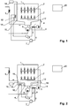
- the device has a fresh water valve 5, through which fresh process water, optionally via a treatment plant, such as. a desalination plant (not shown) to which tub 1 can be supplied.
- a treatment plant such as. a desalination plant (not shown) to which tub 1 can be supplied.
- a drain pump 6 is used for discharging water from the tub 1.
- the device has a heat pump with a compressor 7, a condenser 8, an expansion valve 9 and an evaporator 10.
- the condenser 8 is thermally connected to the tub 1 or the process water circuit. In the present example, it is arranged on the line 12 and / or the feed pump 3. Alternatively or additionally, the capacitor 8 may be thermally coupled to the tub 1.
- the evaporator 10 is thermally coupled to a heat accumulator 14.
- the heat accumulator 14 is preferably designed as a tank in which a heat storage liquid is arranged. This may be e.g. to act water, or the heat storage fluid may be at least partially made of water. Water is preferred because of its high heat capacity and toxic safety.
- the heat accumulator 10 is arranged laterally on at least one wall of the tub 1, but separated from it by a heat coupling tank 16.
- the heat coupling tank 16 has approximately the same area as the heat accumulator 14 in its extension parallel to the tub wall, but its extension perpendicular to the tub wall may be e.g. only a few millimeters.
- the heat coupling tank 16 is disposed on a vertical side wall of the tub 1, for reasons that will become apparent in the operation of the apparatus described below. It is also conceivable, however, an arrangement of the heat coupling tank on a horizontal wall of the tub 1, namely the ceiling or the bottom of the tub 1. A corresponding embodiment will be described below.
- the heat coupling tank 16 is connected to a filler 18 shown only schematically, which serves to supply a coupling fluid to the heat coupling tank 16 and to empty the heat coupling tank 16 from the coupling fluid.
- the coupling fluid preferably again consists at least partially of water.
- the filler 18 may be, for example, a pump which pumps water from another part of the apparatus into and out of the heat coupling tank 16.
- the filler 18 may also be formed, for example, by a valve assembly which is capable of filling fresh water in the heat coupling tank 16 and then drain the water again.
- a controller 20 In the Fig. 1 shown components of the device are controlled by a controller 20.
- a first process phase which is called main wash in the following and which may precede an optional pre-purge phase
- the heat pump 7, 8, 9, 10 is put into operation in order to extract heat from the heat accumulator 14 and supply it to the process water in the tub.
- the heat coupling tank 16 is empty, so that the thermal resistance between the heat accumulator 14 and tub 1 is high.
- the temperature in the heat accumulator 14 can also be lowered to or below the freezing point of the heat storage fluid.
- an electric heater can additionally be used in this phase in order to supply even more energy to the process water or the tub 1.
- the process water is in the main rinsing phase, e.g. heated to a maximum of 40 ° C (depending on the type of process but also up to 70 ° C).
- An intermediate rinsing phase optionally adjoins the main rinsing phase in which the water in the vat is replaced by fresh water with which the dishes are rinsed. Also during this phase, the heat coupling tank 16 remains empty.
- the rinse phase in which the tub 1 is again supplied with fresh water as a further process phase.
- the water is mixed with rinse aid and heated to a relatively high temperature of e.g. Heated to 60 ° C.
- the heat pump and / or the electric heater can be used.
- the heat coupling tank 16 remains empty.
- the heat storage 14 can now heat up to room temperature, as far as he has not yet reached. Then it can be reused by the heat pump for the next cleaning process.
- At least a portion of the heat coupling tank 16 is disposed below the tub 1 and at least a portion of the heat accumulator 14 below the heat coupling tank 16, so that a thermal coupling is achieved at process water, which is in the bottom region of the tub 1.
- FIG. 2 A corresponding design is in Fig. 2 shown.
- the heat storage is arranged annularly around the sump 4 and separated by the likewise approximately annular heat coupling tank 16 from the tub.
- this device may basically be that of the device of Fig. 1 correspond.
- the device described here is particularly suitable for extracting energy from the tub 1 before it is discharged from the tub.
- the device may e.g. operated as follows.
- the heat coupling tank 16 is initially empty again and the process water is heated.
- heating e.g. uses an electric heater, or it is, as described above, a laterally arranged on the tub heat accumulator 14 is used, which is extracted from the heat pump heat to supply it to the tub.
- the heat coupling tank 16 is flooded under the bottom of the tub 1 so that the warm process water standing or flowing in the bottom area of the tub is thermally coupled to the heat storage 14 and gives off part of its heat to the heat storage tank 14. Then, the now partially cooled process water is removed and the heat coupling tank 16 is emptied.
- the heat accumulator can thus be used to transfer heat from a first process phase into a later second process phase.
- a heat coupling tank 16 is arranged on the outside of the tub 1.
- the tub 1 is double-walled, wherein the heat coupling tank 16 is formed between the two walls of the tub.
- the heat coupling tank 16 is arranged substantially around the entire tub 1 around, so that there is a large contact area.
- the heat accumulator 14 is arranged, whereby he also has a large contact area with the heat coupling tank 16.
- the heat storage 14 may consist of a tank with a liquid or of a solid or powdery mass, which has a high heat capacity or can phase-convert in the relevant temperature range.
- a filler 18 is provided, which serves to supply a coupling fluid to the heat coupling tank 16 and to empty the heat coupling tank 16 from the coupling fluid
- the food can be heated, for example, initially with empty heat coupling tank. After the food is ready, they are removed from the process room, and now the heat coupling tank can be filled, so that a part of the residual heat of the process chamber can go into the heat storage. This heat can be reused later, especially if a subcoolable latent heat storage is used, cf. next section.
- the heat accumulator is a subcoolable latent heat storage, i. a latent heat storage having two phase states, e.g. solid and liquid, wherein the higher temperature range associated first phase state can be subcooled well below the phase transition temperature.
- This undercoolable latent heat accumulator is further preferably equipped with an initiator to initiate or at least promote the phase transition from the first phase state back to the second phase state when the latent heat accumulator is overcooled. This makes it possible to selectively release the latent heat at a desired time.
- This design of the heat accumulator can basically be used for all types of equipment mentioned above, such as dishwashers, washing machines or cooking appliances.
- heat can be supplied to the latent heat storage by filling the heat coupling tank with a warm process space to bring it into the first phase state bring to. Then the device can cool down, but the latent heat storage remains undercooled in the first phase state. If the heat is then required for a later process cycle, eg for a later cleaning cycle or cooking cycle, then the heat coupling tank is filled and the initiator is actuated, so that heat is released, which can be at least partially returned to the process space. Thereafter, the heat coupling tank is emptied, and the process room is further heated if necessary.
- the latent heat storage is based on a "phase change material” (PCM) which undergoes a phase transition at a phase transition temperature Tc, which is preferably above 50 ° C and below 200 ° C, so that it can be melted with the residual heat of typical oven temperatures. Furthermore, the material should be allowed to be subcooled to at least room temperature, so that the latent heat can be stored until the next use. Finally, the crystallization of the supercooled material or the transition from the first (higher) phase state to the second (deeper) phase state must be able to be specifically triggered so that the latent heat can be conveyed back to the muffle area at the right time. For this purpose, an initiator is provided.
- PCM phase transition temperature
- phase change material sodium acetate trihydrate (melting point 58 ° C)
- im U.S. Patent 5,728,316 mentioned mixture of magnesium nitrate hexahydrate Mg (NO3) 2 ⁇ 6 H2O with lithium nitrate LiN03 (melting point 75.6 ° C) and similar mixtures known from EP 1 087 003 or potassium aluminum dodecylhydrate (melting point 92 ° C) are used, and the other in EP 689,024 and EP 1 186 838 mentioned materials.
- Most materials of this type use a solid-liquid phase transition.
- the type of phase transition plays in the present context only minor role. It is crucial that the latent heat storage can be brought by heating in the first phase state with thermal coupling to the muffle and then subcooled.
- a mechanical initiator can be used, which is designed for example in the manner of a "crackpot frog", i. as a metal plate, which changes its configuration when force application jumps.
- the initiator is connected to an electromagnetic actuator that can actuate the initiator.
- initiators by ultrasound, pressure, chemical initiators as nucleating agents and electrical initiators with which the crystallization is initiated directly by applying a voltage, cf. eg EP 689,024 and EP 1 186 838 ,
- the heat pump itself can also be used as an initiator by cooling the heat exchanger of the heat pump connected to the latent heat accumulator to such a low temperature that the transition from the first to the second phase state takes place spontaneously.
- the thermal contact between the process chamber and heat storage can be changed in a targeted and controlled manner in a simple manner.
- manipulated variables for initiating a filling or emptying of the heat coupling tank are e.g. Time, degree of filling, temperature of the tub or temperature of the heat storage in question, or a combination of several of these sizes.
- the heat coupling tank makes it possible to heat or cool the heat accumulator independently of or with a time delay to the process space and to thermally couple it to the process space as required by filling the heat coupling tank. There are no complicated mechanical actuators required for this purpose.
- the degree of heat coupling can be infinitely adjusted via the filling level.
- the heat coupling tank may be disposed on one or more walls of the tub. Also conceivable is an arrangement inside the tub.
- heat may be added to the heat storage by placing wastewater in thermal contact with it before it is drained.
- wastewater in thermal contact with it before it is drained.
- the in EP2096203 described wastewater tank 6 on the outside of in Fig. 3 shown heat accumulator 14 are arranged.
- the heat accumulator as well as the heat coupling tank also provide some sound insulation so that noises from the process space, such as e.g. can occur during dishwashing, be better damped.
Priority Applications (4)
| Application Number | Priority Date | Filing Date | Title |
|---|---|---|---|
| PL10002683T PL2193741T3 (pl) | 2010-03-15 | 2010-03-15 | Sprzęt gospodarstwa domowego z zasobnikiem ciepła i pojemnikiem sprzęgającym ciepło |
| EP10002683.0A EP2193741B1 (de) | 2010-03-15 | 2010-03-15 | Haushaltgerät mit Wärmespeicher und Wärmekopplungstank |
| SI201031714T SI2193741T1 (en) | 2010-03-15 | 2010-03-15 | A household appliance with a heat storage device and a thermal coupling |
| DK10002683.0T DK2193741T3 (da) | 2010-03-15 | 2010-03-15 | Husholdningsapparat med varmelager og varmekoblingstank |
Applications Claiming Priority (1)
| Application Number | Priority Date | Filing Date | Title |
|---|---|---|---|
| EP10002683.0A EP2193741B1 (de) | 2010-03-15 | 2010-03-15 | Haushaltgerät mit Wärmespeicher und Wärmekopplungstank |
Publications (3)
| Publication Number | Publication Date |
|---|---|
| EP2193741A2 EP2193741A2 (de) | 2010-06-09 |
| EP2193741A3 EP2193741A3 (de) | 2010-09-08 |
| EP2193741B1 true EP2193741B1 (de) | 2018-04-25 |
Family
ID=42136356
Family Applications (1)
| Application Number | Title | Priority Date | Filing Date |
|---|---|---|---|
| EP10002683.0A Active EP2193741B1 (de) | 2010-03-15 | 2010-03-15 | Haushaltgerät mit Wärmespeicher und Wärmekopplungstank |
Country Status (4)
| Country | Link |
|---|---|
| EP (1) | EP2193741B1 (da) |
| DK (1) | DK2193741T3 (da) |
| PL (1) | PL2193741T3 (da) |
| SI (1) | SI2193741T1 (da) |
Families Citing this family (28)
| Publication number | Priority date | Publication date | Assignee | Title |
|---|---|---|---|---|
| DE102010029873A1 (de) * | 2010-06-09 | 2011-12-15 | BSH Bosch und Siemens Hausgeräte GmbH | Hausgerät, insbesondere Haushaltsreinigungsgerät |
| SI2224049T1 (sl) * | 2010-06-11 | 2013-02-28 | V-Zug Ag | Naprava za čiščenje z rezervoarjem odpadne vode in toplotno črpalko in postopek za krmiljenje te naprave za čiščenje |
| EP2471434A1 (en) * | 2010-12-29 | 2012-07-04 | Electrolux Home Products Corporation N.V. | A household appliance |
| DE102011000042A1 (de) * | 2011-01-05 | 2012-07-05 | Miele & Cie. Kg | Verfahren zum Durchführen eines Spülprogramms |
| PL2322072T3 (pl) | 2011-02-18 | 2014-05-30 | V Zug Ag | Zmywarka do naczyń z zasobnikiem ciepła utajonego |
| DE102011110777B4 (de) | 2011-08-22 | 2019-05-02 | Thyssenkrupp Steel Europe Ag | Vorrichtung zur Körperschalldämpfung und Luftschalldämmung mit flexiblen Wärmedämmeigenschaften |
| EP2662013A1 (en) * | 2012-05-07 | 2013-11-13 | ELECTROLUX PROFESSIONAL S.p.A. | A dishwashing machine with a heat-pump drying device and associated method |
| DE102012105907A1 (de) * | 2012-07-03 | 2014-01-09 | Miele & Cie. Kg | Geschirrspülmaschine und Verfahren zum Betreiben einer Geschirrspülmaschine |
| EP2992132B1 (en) * | 2013-04-30 | 2020-02-26 | Electrolux Appliances Aktiebolag | Washing machine with heat pump |
| WO2014177187A1 (en) * | 2013-04-30 | 2014-11-06 | Electrolux Appliances Aktiebolag | Heat pump washing apparatus |
| DE102013216741B3 (de) * | 2013-08-23 | 2014-12-11 | BSH Bosch und Siemens Hausgeräte GmbH | Haushaltsgerät mit Spülwasserbehälter |
| DE102013019185A1 (de) * | 2013-11-18 | 2015-05-21 | Stiebel Eltron Gmbh & Co. Kg | Geschirrspülmaschine mit einem Spülflüssigkeitskreislauf |
| EP3129541B1 (en) | 2014-04-07 | 2019-05-22 | Whirlpool EMEA S.p.A | Washing and drying machine |
| WO2016134938A1 (de) * | 2015-02-27 | 2016-09-01 | BSH Hausgeräte GmbH | Haushalts-geschirrspülmaschine zum waschen von spülgut in ein oder mehreren teilspülgängen sowie zugehöriges verfahren |
| DE102015222917A1 (de) * | 2015-11-20 | 2017-05-24 | BSH Hausgeräte GmbH | Geschirrspülmaschine sowie Verfahren zum Betreiben einer solchen |
| DE102015222971B3 (de) * | 2015-11-20 | 2016-12-22 | BSH Hausgeräte GmbH | Geschirrspülmaschine mit einer Wärmepumpeneinrichtung |
| CN105615809B (zh) * | 2016-03-22 | 2019-08-27 | 卓汇化工有限公司 | 清洗装置及其热回收系统 |
| ES2642117B1 (es) * | 2016-05-12 | 2018-09-13 | Bsh Electrodomésticos España, S.A. | Máquina lavavajillas y procedimiento para lavar y secar artículos de lavado |
| WO2018215343A1 (de) * | 2017-05-23 | 2018-11-29 | Miele & Cie. Kg | Reinigungsgerät und verfahren zum betrieb eines reinigungsgeräts |
| CN110678113B (zh) | 2017-05-23 | 2023-04-14 | 美诺两合公司 | 洗碗碟机和操作洗碗碟机的方法 |
| ES2702491A1 (es) * | 2017-09-01 | 2019-03-01 | Bsh Electrodomesticos Espana Sa | Máquina lavavajillas doméstica con disposición de tanque |
| ES2703474A1 (es) * | 2017-09-08 | 2019-03-08 | Bsh Electrodomesticos Espana Sa | Maquina lavavajillas domestica con disposicion de bomba de calor y procedimiento para su puesta en funcionamiento |
| CN109620083A (zh) * | 2017-10-09 | 2019-04-16 | 青岛海尔洗碗机有限公司 | 一种热泵洗碗机 |
| CN107858811B (zh) * | 2017-12-08 | 2023-06-27 | 珠海格力电器股份有限公司 | 滚筒洗衣机及其控制方法 |
| DE102018100013A1 (de) * | 2018-01-02 | 2019-07-04 | Miele & Cie. Kg | Geschirrspülmaschine, insbesondere Haushaltsgeschirrspülmaschine |
| ES2723980A1 (es) * | 2018-02-27 | 2019-09-04 | Bsh Electrodomesticos Espana Sa | Máquina lavavajillas doméstica con disposición de tanque |
| ES2754880A1 (es) * | 2018-10-18 | 2020-04-20 | Bsh Electrodomesticos Espana Sa | Máquina Lavavajillas doméstica con bomba de calor |
| WO2021004605A1 (en) * | 2019-07-05 | 2021-01-14 | Electrolux Appliances Aktiebolag | Washing appliance |
Family Cites Families (10)
| Publication number | Priority date | Publication date | Assignee | Title |
|---|---|---|---|---|
| DE3609277A1 (de) * | 1986-03-19 | 1987-09-24 | Ascher Erhard | Wasch- oder spuelmaschine mit einem waermetauscher |
| DE19622882C2 (de) * | 1996-06-07 | 2000-05-18 | Aeg Hausgeraete Gmbh | Geschirrspülmaschine |
| DE29618243U1 (de) * | 1996-10-08 | 1996-12-19 | Bodach Rolf Dipl Ing Fh | Doppelwandiger Wasch- und Speicherbehälter mit Kühlschlange, zur Wiederverwendung von Waschlauge und Spülwasser in Haushaltstrommelwaschmaschinen |
| DE29703763U1 (de) * | 1997-03-01 | 1997-07-03 | Huelse Michael | Waschmaschine |
| DE19758061C2 (de) * | 1997-12-29 | 2002-09-26 | Bsh Bosch Siemens Hausgeraete | Vorratsbehälter für wasserführende Haushaltgeräte |
| JP2001008880A (ja) * | 1999-06-29 | 2001-01-16 | Noritz Corp | 食器洗い乾燥機 |
| RU2009145956A (ru) * | 2007-05-11 | 2011-06-20 | Авеко Эпплаинс Системз Гмбх Унд Ко. Кг (De) | Бытовое устройство, в частности посудомоечная машина, с теплообменником |
| DE502007002839D1 (de) * | 2007-06-14 | 2010-04-01 | V Zug Ag | Geschirrspüler mit Wärmerückgewinnung |
| FR2934485B1 (fr) * | 2008-07-29 | 2012-12-28 | Fagorbrandt Sas | Appareil de lavage et procede de recuperation d'energie calorifique d'au moins un bain de liquide de lavage et/ou de rincage |
| PL2096203T3 (pl) * | 2009-05-28 | 2012-05-31 | V Zug Ag | Pralka do gospodarstwa domowego z pompą cieplną |
-
2010
- 2010-03-15 DK DK10002683.0T patent/DK2193741T3/da active
- 2010-03-15 EP EP10002683.0A patent/EP2193741B1/de active Active
- 2010-03-15 SI SI201031714T patent/SI2193741T1/en unknown
- 2010-03-15 PL PL10002683T patent/PL2193741T3/pl unknown
Non-Patent Citations (1)
| Title |
|---|
| None * |
Also Published As
| Publication number | Publication date |
|---|---|
| PL2193741T3 (pl) | 2018-09-28 |
| EP2193741A3 (de) | 2010-09-08 |
| SI2193741T1 (en) | 2018-08-31 |
| DK2193741T3 (da) | 2018-07-23 |
| EP2193741A2 (de) | 2010-06-09 |
Similar Documents
| Publication | Publication Date | Title |
|---|---|---|
| EP2193741B1 (de) | Haushaltgerät mit Wärmespeicher und Wärmekopplungstank | |
| EP2206824B1 (de) | Haushaltgerät mit Bottich, Wärmepumpe und Tank | |
| EP3261509B1 (de) | Haushalts-geschirrspülmaschine zum waschen von spülgut in ein oder mehreren teilspülgängen sowie zugehöriges verfahren | |
| EP2064982B1 (de) | Geschirrspüler mit Wärmepumpe | |
| EP2322072B1 (de) | Geschirrspüler mit Latentwärmespeicher | |
| CH699692B1 (de) | Geschirrspüler mit mehreren Wassertanks. | |
| EP3372140B1 (de) | Geschirrspülmaschine, insbesondere haushaltsgeschirrspülmaschine | |
| WO2006063895A1 (de) | Haushalts-geschirrspülmaschine und verfahren zum betreiben derselben | |
| EP1953458A1 (de) | Verfahren zur Reinigung eines Gargeräts und Gargerät hierfür | |
| EP3021731B1 (de) | Geschirrspülmaschine und verfahren zum betrieb einer geschirrspülmaschine mit einem in einem wasserbehälter integrierten abflussrohrleitungsabschnitt | |
| DE102015203532A1 (de) | Haushalts- Geschirrspülmaschine zum Waschen von Spülgut in ein oder mehreren Teilspülgängen sowie zugehöriges Verfahren | |
| DE102015116553B3 (de) | Verfahren zum Betrieb eines Wärmetauschers einer Geschirrspülmaschine | |
| DE102009029185A1 (de) | Geschirrspülmaschine mit Vorratsbehälter sowie zugehöriges Vorheizverfahren | |
| DE102012207565A1 (de) | Verfahren zum Betreiben einer als Programmautomat ausgebildeten Spülmaschine sowie entsprechende Spülmaschine | |
| EP3797669A1 (de) | Geschirrspülmaschine | |
| DE102019131958A1 (de) | Geschirrspülmaschine mit Wärmepumpe | |
| DE102015226481A1 (de) | Haushalts- Geschirrspülmaschine zum Waschen von Spülgut in ein oder mehreren Teilspülgängen sowie zugehöriges Verfahren | |
| EP3675704A1 (de) | Haushaltsgeschirrspülmaschine mit tankanordnung | |
| EP3456237B1 (de) | Geschirrspülmaschine mit zumindest einer wärmepumpe | |
| EP2289388B1 (de) | Geschirrspülmaschine mit einem Wasserbehälter zur Kondensationstrocknung sowie zugehöriges Füllverfahren | |
| EP3021728B1 (de) | Geschirrspülmaschine mit einem in einem wasserbehälter integrierten abflussrohrleitungsabschnitt | |
| EP3747334A1 (de) | Haushaltsgeschirrspülmaschine mit zumindest einer wärmepumpe | |
| DE102016102334A1 (de) | Geschirrspüler mit Bereitschaftsprogramm | |
| EP3170437B1 (de) | Geschirrspülmaschine sowie verfahren zum betreiben einer solchen | |
| DE102019202625A1 (de) | Haushaltsgeschirrspülmaschine mit Wärmepumpenanordnung |
Legal Events
| Date | Code | Title | Description |
|---|---|---|---|
| PUAI | Public reference made under article 153(3) epc to a published international application that has entered the european phase |
Free format text: ORIGINAL CODE: 0009012 |
|
| AK | Designated contracting states |
Kind code of ref document: A2 Designated state(s): AT BE BG CH CY CZ DE DK EE ES FI FR GB GR HR HU IE IS IT LI LT LU LV MC MK MT NL NO PL PT RO SE SI SK SM TR |
|
| AX | Request for extension of the european patent |
Extension state: AL BA ME RS |
|
| PUAL | Search report despatched |
Free format text: ORIGINAL CODE: 0009013 |
|
| AK | Designated contracting states |
Kind code of ref document: A3 Designated state(s): AT BE BG CH CY CZ DE DK EE ES FI FR GB GR HR HU IE IS IT LI LT LU LV MC MK MT NL NO PL PT RO SE SI SK SM TR |
|
| AX | Request for extension of the european patent |
Extension state: AL BA ME RS |
|
| RIC1 | Information provided on ipc code assigned before grant |
Ipc: F24C 15/34 20060101ALI20100802BHEP Ipc: A47L 15/42 20060101AFI20100430BHEP Ipc: D06F 39/00 20060101ALI20100802BHEP |
|
| 17P | Request for examination filed |
Effective date: 20110207 |
|
| GRAP | Despatch of communication of intention to grant a patent |
Free format text: ORIGINAL CODE: EPIDOSNIGR1 |
|
| STAA | Information on the status of an ep patent application or granted ep patent |
Free format text: STATUS: GRANT OF PATENT IS INTENDED |
|
| RIC1 | Information provided on ipc code assigned before grant |
Ipc: D06F 37/26 20060101ALI20180115BHEP Ipc: A47L 15/42 20060101AFI20180115BHEP Ipc: D06F 39/00 20060101ALI20180115BHEP |
|
| INTG | Intention to grant announced |
Effective date: 20180206 |
|
| GRAA | (expected) grant |
Free format text: ORIGINAL CODE: 0009210 |
|
| GRAS | Grant fee paid |
Free format text: ORIGINAL CODE: EPIDOSNIGR3 |
|
| STAA | Information on the status of an ep patent application or granted ep patent |
Free format text: STATUS: THE PATENT HAS BEEN GRANTED |
|
| AK | Designated contracting states |
Kind code of ref document: B1 Designated state(s): AT BE BG CH CY CZ DE DK EE ES FI FR GB GR HR HU IE IS IT LI LT LU LV MC MK MT NL NO PL PT RO SE SI SK SM TR |
|
| REG | Reference to a national code |
Ref country code: GB Ref legal event code: FG4D Free format text: NOT ENGLISH |
|
| REG | Reference to a national code |
Ref country code: CH Ref legal event code: EP Ref country code: CH Ref legal event code: NV Representative=s name: E. BLUM AND CO. AG PATENT- UND MARKENANWAELTE , CH |
|
| REG | Reference to a national code |
Ref country code: AT Ref legal event code: REF Ref document number: 991958 Country of ref document: AT Kind code of ref document: T Effective date: 20180515 |
|
| REG | Reference to a national code |
Ref country code: IE Ref legal event code: FG4D Free format text: LANGUAGE OF EP DOCUMENT: GERMAN |
|
| REG | Reference to a national code |
Ref country code: DE Ref legal event code: R096 Ref document number: 502010014898 Country of ref document: DE |
|
| REG | Reference to a national code |
Ref country code: DK Ref legal event code: T3 Effective date: 20180716 |
|
| RAP2 | Party data changed (patent owner data changed or rights of a patent transferred) |
Owner name: V-ZUG AG |
|
| REG | Reference to a national code |
Ref country code: SE Ref legal event code: TRGR |
|
| REG | Reference to a national code |
Ref country code: NL Ref legal event code: MP Effective date: 20180425 |
|
| REG | Reference to a national code |
Ref country code: LT Ref legal event code: MG4D |
|
| PG25 | Lapsed in a contracting state [announced via postgrant information from national office to epo] |
Ref country code: NL Free format text: LAPSE BECAUSE OF FAILURE TO SUBMIT A TRANSLATION OF THE DESCRIPTION OR TO PAY THE FEE WITHIN THE PRESCRIBED TIME-LIMIT Effective date: 20180425 |
|
| PG25 | Lapsed in a contracting state [announced via postgrant information from national office to epo] |
Ref country code: ES Free format text: LAPSE BECAUSE OF FAILURE TO SUBMIT A TRANSLATION OF THE DESCRIPTION OR TO PAY THE FEE WITHIN THE PRESCRIBED TIME-LIMIT Effective date: 20180425 Ref country code: LT Free format text: LAPSE BECAUSE OF FAILURE TO SUBMIT A TRANSLATION OF THE DESCRIPTION OR TO PAY THE FEE WITHIN THE PRESCRIBED TIME-LIMIT Effective date: 20180425 Ref country code: BG Free format text: LAPSE BECAUSE OF FAILURE TO SUBMIT A TRANSLATION OF THE DESCRIPTION OR TO PAY THE FEE WITHIN THE PRESCRIBED TIME-LIMIT Effective date: 20180725 Ref country code: NO Free format text: LAPSE BECAUSE OF FAILURE TO SUBMIT A TRANSLATION OF THE DESCRIPTION OR TO PAY THE FEE WITHIN THE PRESCRIBED TIME-LIMIT Effective date: 20180725 Ref country code: FI Free format text: LAPSE BECAUSE OF FAILURE TO SUBMIT A TRANSLATION OF THE DESCRIPTION OR TO PAY THE FEE WITHIN THE PRESCRIBED TIME-LIMIT Effective date: 20180425 |
|
| PG25 | Lapsed in a contracting state [announced via postgrant information from national office to epo] |
Ref country code: GR Free format text: LAPSE BECAUSE OF FAILURE TO SUBMIT A TRANSLATION OF THE DESCRIPTION OR TO PAY THE FEE WITHIN THE PRESCRIBED TIME-LIMIT Effective date: 20180726 Ref country code: HR Free format text: LAPSE BECAUSE OF FAILURE TO SUBMIT A TRANSLATION OF THE DESCRIPTION OR TO PAY THE FEE WITHIN THE PRESCRIBED TIME-LIMIT Effective date: 20180425 Ref country code: LV Free format text: LAPSE BECAUSE OF FAILURE TO SUBMIT A TRANSLATION OF THE DESCRIPTION OR TO PAY THE FEE WITHIN THE PRESCRIBED TIME-LIMIT Effective date: 20180425 |
|
| PG25 | Lapsed in a contracting state [announced via postgrant information from national office to epo] |
Ref country code: PT Free format text: LAPSE BECAUSE OF FAILURE TO SUBMIT A TRANSLATION OF THE DESCRIPTION OR TO PAY THE FEE WITHIN THE PRESCRIBED TIME-LIMIT Effective date: 20180827 |
|
| REG | Reference to a national code |
Ref country code: DE Ref legal event code: R097 Ref document number: 502010014898 Country of ref document: DE |
|
| PG25 | Lapsed in a contracting state [announced via postgrant information from national office to epo] |
Ref country code: RO Free format text: LAPSE BECAUSE OF FAILURE TO SUBMIT A TRANSLATION OF THE DESCRIPTION OR TO PAY THE FEE WITHIN THE PRESCRIBED TIME-LIMIT Effective date: 20180425 Ref country code: SK Free format text: LAPSE BECAUSE OF FAILURE TO SUBMIT A TRANSLATION OF THE DESCRIPTION OR TO PAY THE FEE WITHIN THE PRESCRIBED TIME-LIMIT Effective date: 20180425 Ref country code: CZ Free format text: LAPSE BECAUSE OF FAILURE TO SUBMIT A TRANSLATION OF THE DESCRIPTION OR TO PAY THE FEE WITHIN THE PRESCRIBED TIME-LIMIT Effective date: 20180425 Ref country code: EE Free format text: LAPSE BECAUSE OF FAILURE TO SUBMIT A TRANSLATION OF THE DESCRIPTION OR TO PAY THE FEE WITHIN THE PRESCRIBED TIME-LIMIT Effective date: 20180425 |
|
| PG25 | Lapsed in a contracting state [announced via postgrant information from national office to epo] |
Ref country code: IT Free format text: LAPSE BECAUSE OF FAILURE TO SUBMIT A TRANSLATION OF THE DESCRIPTION OR TO PAY THE FEE WITHIN THE PRESCRIBED TIME-LIMIT Effective date: 20180425 Ref country code: SM Free format text: LAPSE BECAUSE OF FAILURE TO SUBMIT A TRANSLATION OF THE DESCRIPTION OR TO PAY THE FEE WITHIN THE PRESCRIBED TIME-LIMIT Effective date: 20180425 |
|
| PLBE | No opposition filed within time limit |
Free format text: ORIGINAL CODE: 0009261 |
|
| STAA | Information on the status of an ep patent application or granted ep patent |
Free format text: STATUS: NO OPPOSITION FILED WITHIN TIME LIMIT |
|
| 26N | No opposition filed |
Effective date: 20190128 |
|
| PGFP | Annual fee paid to national office [announced via postgrant information from national office to epo] |
Ref country code: PL Payment date: 20190123 Year of fee payment: 14 Ref country code: GB Payment date: 20190320 Year of fee payment: 10 |
|
| PGFP | Annual fee paid to national office [announced via postgrant information from national office to epo] |
Ref country code: DK Payment date: 20190322 Year of fee payment: 10 |
|
| PG25 | Lapsed in a contracting state [announced via postgrant information from national office to epo] |
Ref country code: MC Free format text: LAPSE BECAUSE OF FAILURE TO SUBMIT A TRANSLATION OF THE DESCRIPTION OR TO PAY THE FEE WITHIN THE PRESCRIBED TIME-LIMIT Effective date: 20180425 |
|
| PG25 | Lapsed in a contracting state [announced via postgrant information from national office to epo] |
Ref country code: LU Free format text: LAPSE BECAUSE OF NON-PAYMENT OF DUE FEES Effective date: 20190315 |
|
| REG | Reference to a national code |
Ref country code: BE Ref legal event code: MM Effective date: 20190331 |
|
| PG25 | Lapsed in a contracting state [announced via postgrant information from national office to epo] |
Ref country code: IE Free format text: LAPSE BECAUSE OF NON-PAYMENT OF DUE FEES Effective date: 20190315 |
|
| PG25 | Lapsed in a contracting state [announced via postgrant information from national office to epo] |
Ref country code: BE Free format text: LAPSE BECAUSE OF NON-PAYMENT OF DUE FEES Effective date: 20190331 |
|
| PG25 | Lapsed in a contracting state [announced via postgrant information from national office to epo] |
Ref country code: TR Free format text: LAPSE BECAUSE OF FAILURE TO SUBMIT A TRANSLATION OF THE DESCRIPTION OR TO PAY THE FEE WITHIN THE PRESCRIBED TIME-LIMIT Effective date: 20180425 |
|
| PG25 | Lapsed in a contracting state [announced via postgrant information from national office to epo] |
Ref country code: MT Free format text: LAPSE BECAUSE OF FAILURE TO SUBMIT A TRANSLATION OF THE DESCRIPTION OR TO PAY THE FEE WITHIN THE PRESCRIBED TIME-LIMIT Effective date: 20180425 |
|
| REG | Reference to a national code |
Ref country code: AT Ref legal event code: MM01 Ref document number: 991958 Country of ref document: AT Kind code of ref document: T Effective date: 20190315 |
|
| REG | Reference to a national code |
Ref country code: DK Ref legal event code: EBP Effective date: 20200331 |
|
| PG25 | Lapsed in a contracting state [announced via postgrant information from national office to epo] |
Ref country code: AT Free format text: LAPSE BECAUSE OF NON-PAYMENT OF DUE FEES Effective date: 20190315 |
|
| PG25 | Lapsed in a contracting state [announced via postgrant information from national office to epo] |
Ref country code: FR Free format text: LAPSE BECAUSE OF NON-PAYMENT OF DUE FEES Effective date: 20200331 |
|
| GBPC | Gb: european patent ceased through non-payment of renewal fee |
Effective date: 20200315 |
|
| PG25 | Lapsed in a contracting state [announced via postgrant information from national office to epo] |
Ref country code: DK Free format text: LAPSE BECAUSE OF NON-PAYMENT OF DUE FEES Effective date: 20200331 Ref country code: GB Free format text: LAPSE BECAUSE OF NON-PAYMENT OF DUE FEES Effective date: 20200315 |
|
| PG25 | Lapsed in a contracting state [announced via postgrant information from national office to epo] |
Ref country code: CY Free format text: LAPSE BECAUSE OF FAILURE TO SUBMIT A TRANSLATION OF THE DESCRIPTION OR TO PAY THE FEE WITHIN THE PRESCRIBED TIME-LIMIT Effective date: 20180425 |
|
| PG25 | Lapsed in a contracting state [announced via postgrant information from national office to epo] |
Ref country code: IS Free format text: LAPSE BECAUSE OF FAILURE TO SUBMIT A TRANSLATION OF THE DESCRIPTION OR TO PAY THE FEE WITHIN THE PRESCRIBED TIME-LIMIT Effective date: 20180825 |
|
| PG25 | Lapsed in a contracting state [announced via postgrant information from national office to epo] |
Ref country code: HU Free format text: LAPSE BECAUSE OF FAILURE TO SUBMIT A TRANSLATION OF THE DESCRIPTION OR TO PAY THE FEE WITHIN THE PRESCRIBED TIME-LIMIT; INVALID AB INITIO Effective date: 20100315 |
|
| PG25 | Lapsed in a contracting state [announced via postgrant information from national office to epo] |
Ref country code: PL Free format text: LAPSE BECAUSE OF NON-PAYMENT OF DUE FEES Effective date: 20200315 |
|
| PG25 | Lapsed in a contracting state [announced via postgrant information from national office to epo] |
Ref country code: MK Free format text: LAPSE BECAUSE OF FAILURE TO SUBMIT A TRANSLATION OF THE DESCRIPTION OR TO PAY THE FEE WITHIN THE PRESCRIBED TIME-LIMIT Effective date: 20180425 |
|
| PGFP | Annual fee paid to national office [announced via postgrant information from national office to epo] |
Ref country code: SI Payment date: 20230302 Year of fee payment: 14 Ref country code: SE Payment date: 20230314 Year of fee payment: 14 |
|
| P01 | Opt-out of the competence of the unified patent court (upc) registered |
Effective date: 20230502 |
|
| PGFP | Annual fee paid to national office [announced via postgrant information from national office to epo] |
Ref country code: CH Payment date: 20230402 Year of fee payment: 14 |
|
| PGFP | Annual fee paid to national office [announced via postgrant information from national office to epo] |
Ref country code: DE Payment date: 20240320 Year of fee payment: 15 |