EP2193310B1 - Kühlkörper und kühlsystem für ein led-modul - Google Patents
Kühlkörper und kühlsystem für ein led-modul Download PDFInfo
- Publication number
- EP2193310B1 EP2193310B1 EP08773996A EP08773996A EP2193310B1 EP 2193310 B1 EP2193310 B1 EP 2193310B1 EP 08773996 A EP08773996 A EP 08773996A EP 08773996 A EP08773996 A EP 08773996A EP 2193310 B1 EP2193310 B1 EP 2193310B1
- Authority
- EP
- European Patent Office
- Prior art keywords
- cooling body
- heat
- air
- heat sink
- led module
- Prior art date
- Legal status (The legal status is an assumption and is not a legal conclusion. Google has not performed a legal analysis and makes no representation as to the accuracy of the status listed.)
- Not-in-force
Links
- 238000001816 cooling Methods 0.000 title claims description 48
- 239000004020 conductor Substances 0.000 claims description 19
- XAGFODPZIPBFFR-UHFFFAOYSA-N aluminium Chemical compound [Al] XAGFODPZIPBFFR-UHFFFAOYSA-N 0.000 claims description 7
- 229910052782 aluminium Inorganic materials 0.000 claims description 7
- 238000001125 extrusion Methods 0.000 claims description 5
- 239000013013 elastic material Substances 0.000 claims description 3
- 238000000034 method Methods 0.000 claims description 3
- 239000004411 aluminium Substances 0.000 claims 1
- 239000003570 air Substances 0.000 description 52
- 238000004519 manufacturing process Methods 0.000 description 7
- 230000017525 heat dissipation Effects 0.000 description 4
- 238000005452 bending Methods 0.000 description 3
- 230000005465 channeling Effects 0.000 description 2
- 230000001737 promoting effect Effects 0.000 description 2
- 238000003892 spreading Methods 0.000 description 2
- RYGMFSIKBFXOCR-UHFFFAOYSA-N Copper Chemical compound [Cu] RYGMFSIKBFXOCR-UHFFFAOYSA-N 0.000 description 1
- 238000004026 adhesive bonding Methods 0.000 description 1
- 230000002411 adverse Effects 0.000 description 1
- 239000012080 ambient air Substances 0.000 description 1
- 238000010276 construction Methods 0.000 description 1
- 229910052802 copper Inorganic materials 0.000 description 1
- 239000010949 copper Substances 0.000 description 1
- 230000001419 dependent effect Effects 0.000 description 1
- 238000005516 engineering process Methods 0.000 description 1
- 238000010438 heat treatment Methods 0.000 description 1
- 239000007788 liquid Substances 0.000 description 1
- 230000004048 modification Effects 0.000 description 1
- 238000012986 modification Methods 0.000 description 1
- 230000002093 peripheral effect Effects 0.000 description 1
- 230000005855 radiation Effects 0.000 description 1
- 239000004065 semiconductor Substances 0.000 description 1
- 238000005476 soldering Methods 0.000 description 1
- 238000009423 ventilation Methods 0.000 description 1
- 230000000007 visual effect Effects 0.000 description 1
- XLYOFNOQVPJJNP-UHFFFAOYSA-N water Substances O XLYOFNOQVPJJNP-UHFFFAOYSA-N 0.000 description 1
Images


Classifications
-
- F—MECHANICAL ENGINEERING; LIGHTING; HEATING; WEAPONS; BLASTING
- F21—LIGHTING
- F21V—FUNCTIONAL FEATURES OR DETAILS OF LIGHTING DEVICES OR SYSTEMS THEREOF; STRUCTURAL COMBINATIONS OF LIGHTING DEVICES WITH OTHER ARTICLES, NOT OTHERWISE PROVIDED FOR
- F21V29/00—Protecting lighting devices from thermal damage; Cooling or heating arrangements specially adapted for lighting devices or systems
- F21V29/50—Cooling arrangements
- F21V29/60—Cooling arrangements characterised by the use of a forced flow of gas, e.g. air
- F21V29/67—Cooling arrangements characterised by the use of a forced flow of gas, e.g. air characterised by the arrangement of fans
-
- F—MECHANICAL ENGINEERING; LIGHTING; HEATING; WEAPONS; BLASTING
- F21—LIGHTING
- F21V—FUNCTIONAL FEATURES OR DETAILS OF LIGHTING DEVICES OR SYSTEMS THEREOF; STRUCTURAL COMBINATIONS OF LIGHTING DEVICES WITH OTHER ARTICLES, NOT OTHERWISE PROVIDED FOR
- F21V15/00—Protecting lighting devices from damage
- F21V15/01—Housings, e.g. material or assembling of housing parts
- F21V15/013—Housings, e.g. material or assembling of housing parts the housing being an extrusion
-
- F—MECHANICAL ENGINEERING; LIGHTING; HEATING; WEAPONS; BLASTING
- F21—LIGHTING
- F21V—FUNCTIONAL FEATURES OR DETAILS OF LIGHTING DEVICES OR SYSTEMS THEREOF; STRUCTURAL COMBINATIONS OF LIGHTING DEVICES WITH OTHER ARTICLES, NOT OTHERWISE PROVIDED FOR
- F21V29/00—Protecting lighting devices from thermal damage; Cooling or heating arrangements specially adapted for lighting devices or systems
- F21V29/50—Cooling arrangements
- F21V29/502—Cooling arrangements characterised by the adaptation for cooling of specific components
- F21V29/507—Cooling arrangements characterised by the adaptation for cooling of specific components of means for protecting lighting devices from damage, e.g. housings
-
- F—MECHANICAL ENGINEERING; LIGHTING; HEATING; WEAPONS; BLASTING
- F21—LIGHTING
- F21V—FUNCTIONAL FEATURES OR DETAILS OF LIGHTING DEVICES OR SYSTEMS THEREOF; STRUCTURAL COMBINATIONS OF LIGHTING DEVICES WITH OTHER ARTICLES, NOT OTHERWISE PROVIDED FOR
- F21V29/00—Protecting lighting devices from thermal damage; Cooling or heating arrangements specially adapted for lighting devices or systems
- F21V29/50—Cooling arrangements
- F21V29/70—Cooling arrangements characterised by passive heat-dissipating elements, e.g. heat-sinks
- F21V29/74—Cooling arrangements characterised by passive heat-dissipating elements, e.g. heat-sinks with fins or blades
-
- F—MECHANICAL ENGINEERING; LIGHTING; HEATING; WEAPONS; BLASTING
- F21—LIGHTING
- F21V—FUNCTIONAL FEATURES OR DETAILS OF LIGHTING DEVICES OR SYSTEMS THEREOF; STRUCTURAL COMBINATIONS OF LIGHTING DEVICES WITH OTHER ARTICLES, NOT OTHERWISE PROVIDED FOR
- F21V29/00—Protecting lighting devices from thermal damage; Cooling or heating arrangements specially adapted for lighting devices or systems
- F21V29/50—Cooling arrangements
- F21V29/70—Cooling arrangements characterised by passive heat-dissipating elements, e.g. heat-sinks
- F21V29/83—Cooling arrangements characterised by passive heat-dissipating elements, e.g. heat-sinks the elements having apertures, ducts or channels, e.g. heat radiation holes
-
- F—MECHANICAL ENGINEERING; LIGHTING; HEATING; WEAPONS; BLASTING
- F21—LIGHTING
- F21V—FUNCTIONAL FEATURES OR DETAILS OF LIGHTING DEVICES OR SYSTEMS THEREOF; STRUCTURAL COMBINATIONS OF LIGHTING DEVICES WITH OTHER ARTICLES, NOT OTHERWISE PROVIDED FOR
- F21V29/00—Protecting lighting devices from thermal damage; Cooling or heating arrangements specially adapted for lighting devices or systems
- F21V29/50—Cooling arrangements
- F21V29/51—Cooling arrangements using condensation or evaporation of a fluid, e.g. heat pipes
-
- F—MECHANICAL ENGINEERING; LIGHTING; HEATING; WEAPONS; BLASTING
- F21—LIGHTING
- F21V—FUNCTIONAL FEATURES OR DETAILS OF LIGHTING DEVICES OR SYSTEMS THEREOF; STRUCTURAL COMBINATIONS OF LIGHTING DEVICES WITH OTHER ARTICLES, NOT OTHERWISE PROVIDED FOR
- F21V29/00—Protecting lighting devices from thermal damage; Cooling or heating arrangements specially adapted for lighting devices or systems
- F21V29/85—Protecting lighting devices from thermal damage; Cooling or heating arrangements specially adapted for lighting devices or systems characterised by the material
-
- F—MECHANICAL ENGINEERING; LIGHTING; HEATING; WEAPONS; BLASTING
- F21—LIGHTING
- F21V—FUNCTIONAL FEATURES OR DETAILS OF LIGHTING DEVICES OR SYSTEMS THEREOF; STRUCTURAL COMBINATIONS OF LIGHTING DEVICES WITH OTHER ARTICLES, NOT OTHERWISE PROVIDED FOR
- F21V29/00—Protecting lighting devices from thermal damage; Cooling or heating arrangements specially adapted for lighting devices or systems
- F21V29/85—Protecting lighting devices from thermal damage; Cooling or heating arrangements specially adapted for lighting devices or systems characterised by the material
- F21V29/89—Metals
-
- F—MECHANICAL ENGINEERING; LIGHTING; HEATING; WEAPONS; BLASTING
- F21—LIGHTING
- F21Y—INDEXING SCHEME ASSOCIATED WITH SUBCLASSES F21K, F21L, F21S and F21V, RELATING TO THE FORM OR THE KIND OF THE LIGHT SOURCES OR OF THE COLOUR OF THE LIGHT EMITTED
- F21Y2115/00—Light-generating elements of semiconductor light sources
- F21Y2115/10—Light-emitting diodes [LED]
Definitions
- the invention relates to a heat sink for an LED module (LED: light-emitting diode) with an elongate air ducting area for guiding an air movement along the main extension of the air ducting area for the removal of heat. Furthermore, the invention relates to a cooling system for an LED module, wherein the cooling system comprises a heat sink according to the invention; Furthermore, the invention relates to a corresponding LED module.
- LED light-emitting diode
- LED module is a luminaire or a lighting unit is designated, which has at least one LED as the light source.
- an LED module may comprise a printed circuit board equipped with at least one LED as the light source.
- An essential aspect of luminaires that have an LED as a light source is to ensure sufficient cooling of the LED or the luminaire.
- a correspondingly good cooling is necessary in particular in order to ensure a high light output of the LED for a long time.
- the heat generated during operation in the LED and thus in the smallest possible space must therefore be effectively channeled away from the place of origin for this purpose and subsequently released to the environment.
- the LED thermally connect to a heat conductor and this in turn with a heat sink having a large, the power corresponding surface to the heat transfer to the environment by convection and radiation to be able to ensure.
- the heat conductor can be, for example, a so-called "heat pipe” or a plurality of such heat pipes.
- a heat pipe is an elongated tube that can be soldered to the back of an LED module, for example. There is some liquid in the tube, for example water, which evaporates when heated, for example because of corresponding heating of the LED, so that the steam then spreads within the heat pipe. In colder areas of the heat pipe, the steam then condenses again and there is a cooling down.
- the heat sink can be, for example, lamellar wings which are connected to heat pipes. As a result, the heat exchange between the Heatpipes and the environment improved.
- the wings are formed at a 90 ° angle and are arranged one behind the other in the longitudinal direction of the heat pipes.
- the wings each have openings through which the heat pipes protrude. In this arrangement, there is the problem that the thermal connection between the heat pipes and the wings is relatively poor, since there is only a quasi "punctiform" or linear connection at the openings of the wings.
- a corresponding device is described with a heat sink, in which the wings extend in the longitudinal direction of the heatpipes, wherein the heat sink is further configured so that it contacts the heatpipes area, so that at this point a better heat transfer can take place.
- From the EP 1 763 090 A2 is a light emitting diode array with a cooling device known.
- the arrangement has elongated air ducting areas for the removal of heat.
- a semiconductor device heatsink having cooling fins is known.
- the outer corners of the ribs are shaped so that the inside width increases towards the inside.
- the present invention has for its object to provide a heat sink for an LED module, with a particularly effective cooling with simple production of the LED module is possible; a corresponding task arises for a corresponding cooling system for an LED module or for such an LED module itself.
- the heat sink can be designed so that the external appearance is not dominated by a rib or lamellar structure or the like.
- the heat sink can be used as such better than housing exterior of a corresponding LED module.
- a more effective cooling of the LED module is possible, because it can be dispensed with a separate housing or such a housing can at least be designed so that it does not completely surround the heat sink.
- a more targeted air flow is possible, so that the heat sink also has an improved heat conductor function. This makes it possible, with a particular LED module on a separate heat conductor, ie z. B. on heatpipes to dispense. This in turn allows a simpler design of an LED module and thus a more cost-effective production.
- the opening is a gap extending along the main extension of the air ducting area.
- the heat sink has a plurality of air guide regions arranged parallel to one another.
- the air ducts may be arranged annularly.
- the heat sink advantageously has an outer wall region having the opening-or, if appropriate, the openings-which describes a cylinder section, for example a circular cylinder section.
- the proportion of the opening-or in the case of several openings, the proportion of all openings-on the entire surface of the cylinder section is between 10% and 50%, preferably between 20% and 40%.
- the heat sink can be designed so that it can be used on the one hand as a housing or housing part of an LED module and on the other hand still allows a very good heat exchange with the environment.
- the heat sink is produced in an extrusion process. This allows a particularly simple production.
- the heat sink is made of aluminum. He is preferably anodized and / or painted and / or blank.
- the heat sink has a profile shape.
- the power of the heat sink can be selected or varied particularly simply by selecting a corresponding length or by selecting a corresponding diameter.
- the heat sink may thus be provided in the form of an extrusion profile, for example in the form of an aluminum extrusion profile.
- the heat sink is made of an elastic material or has at least elastic regions. This can facilitate a possible connection with a heat conductor, for example in the form of a heat pipe.
- a cooling system for an LED module which has a heat sink according to the invention, and a heat conductor, which is thermally connected to the heat sink.
- the heat conductor is advantageously frictionally connected to the heat sink, preferably connected by clamping. This allows a particularly good heat transfer.
- the heat conductor is connected to the heat sink surface.
- the heat transfer is favored.
- the cooling system further comprises a fan for promoting the movement of air through the air ducting area.
- a cooling system for an LED module which has a heat sink according to the invention, and a fan for promoting the air movement through the air duct area.
- a heat sink according to the invention Characterized in that the heat sink according to the invention per se allows a more targeted air flow, the combination of such a heat sink with a fan without a separate heat conductor is particularly advantageous.
- an LED module which has at least one LED, and a heat sink according to the invention or a cooling system according to the invention, wherein the LED is thermally connected to the heat sink.
- the thermal connection between LED and heat sink can be be provided either directly or indirectly, for example via an optionally provided heat conductor.
- the heat sink can be connected directly to the heat source, that is to say to the LED or a corresponding circuit board or printed circuit board, for example by being glued or soldered. This eliminates the need for a separate heat conductor.
- the heat sink forms a portion of a housing of the LED module.
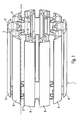
- FIG. 1 an inventive heat sink 1 is sketched according to an embodiment in a perspective view.
- the heat sink 1 is suitable as a cooling element for an LED module.
- the heat sink 1 has an elongated air guide region 2, which serves to guide air movement along its main extension L for the removal of heat.
- FIG. 2 is a cross-sectional view of the heat sink 1 after FIG. 1 outlined.
- the air guide region 2 has an outwardly A leading opening 3.
- “outside” refers to an exterior space with respect to the heat sink 1, that is to say the “environment” of the heat sink 1 to which heat is to be given off by the heat sink 1.
- the inside width of the air guide region 2 increases from the opening 3 inwards towards I.
- clear width is the inner transverse extent of the air duct 2 in a plane normal to the outward A direction indicating.
- With “outward” and “inward” are still 180 ° apart directions designated.
- the diameter of the air duct 2 may be significantly larger than the diameter of the opening 3, for example, twice or three times as large as this FIG. 2 evident.
- the opening 3 is given in the form of a gap which extends along the main extension L of the air duct 2.
- the heat sink 1 has a plurality of air guide regions 2, 2 ', 2 ", which are arranged parallel to one another FIGS. 1 and 2
- the air-guiding regions 2, 2 ', 2 " can, for example, be arranged annularly viewed in cross section and each have an opening 3, 3', for example a gap, in each case after outside A, ie in each case in a direction which leads away from the center of the annular arrangement.
- 3' for example a gap
- the air guide regions 2, 2', 2 " are arranged symmetrically to one another, for example axially symmetrical, as in the exemplary embodiment in FIGS FIGS. 1 and 2 shown, wherein the openings 3, 3 'then each outwardly A, thus point away from the center of symmetry.
- the heat sink 1 has a circular circumference. In this way, the heat sink 1 forms a cylindrical section-shaped outer wall region 6 in the form of a tubular section, which has the openings 3, 3 '. By the outer wall portion 6 so a cylinder section is set.
- the size of the opening 3, 3 'or of the gap is advantageously dimensioned such that on the one hand heat can escape to a considerable extent from the interior I of the air guide region 2, 2', 2 "to the outside A by convection or air movement, but on the other hand as well small or narrow, that the visual appearance of the heat sink 1 is not dominated by internal walls of the air duct 2, 2 ', 2 "when viewed from the outside.
- the heat sink 1 has a (in the example shown circular) circumferential length which is interrupted to less than half of the opening 3 and 3 of the openings 3, 3 '.
- this is given as in the consideration of FIG. 2 becomes clear.
- the circumference to the openings in the form of the openings 3, 3 'behaves as U 1 to U 2 , wherein U 2 is smaller than half of U 1 as shown in the sketch of FIG. 2 can be easily estimated.
- the proportion of the opening 3 or, in the case of several openings, the proportion of the openings 3, 3 'on the entire surface of the cylinder section is between 10% and 50 %, preferably between 20% and 40%, so for example may be about 30%.
- the heat sink 1 profile shape. This allows in a particularly simple manner, the length of the heat sink 1 and thus to vary its surface, so that in a particularly simple manner, the production of heat sinks of different lengths and thus different cooling capacity is possible.
- the heat sink can be adapted exactly to a desired cooling performance. Also by a modification of the diameter of the heat sink 1, the cooling capacity can be changed comparatively easily.
- a housing with longitudinal slots is thus formed by the heat sink 1, so that further embedding in an additional housing is no longer required. Accordingly, the heat exchange with the environment is improved.
- the heat sink 1 is produced in an extrusion process, whereby a particularly simple production is possible.
- the heat sink 1 may be provided in one piece.
- the heat sink 1 made of aluminum, preferably at least partially anodized and / or painted and / or bright. It can therefore be provided be that the heat sink 1 is provided in the form of an extruded aluminum.
- the heat sink 1 can be connected to a heat conductor, for example in the form of heat pipes 8, 8 ', and in this way a cooling system for an LED module is formed.
- a heat conductor for example in the form of heat pipes 8, 8 '
- Such heat pipes 8, 8 ' in the example shown six heat pipes 8, 8', are in the cross-sectional view of FIG. 2 shown, as well as in the perspective sectional view of FIG. 3 ,
- the heat pipes 8, 8 ' may preferably consist of copper.
- the heat pipes 8, 8 ' can extend substantially over the entire length of the heat sink 1. Furthermore, with respect to the length of the heat pipes 8, 8 'may be provided that they on one side of the heat sink 1 - with reference to the illustration of FIG. 3 on the right side - extend beyond and are connected at their local end with an LED unit 12, for example, glued or soldered, so that a good thermal contact is possible.
- the LED unit 12 may be, for example, a printed circuit board on which a LED or a plurality of LEDs are arranged as the light source in a conventional manner. This is known per se from the prior art and is therefore not explained in detail at this point.
- the heat conductor or the heat pipes 8, 8 ' are connected to the heat sink 1 flat and non-positively, preferably by clamping.
- the heat sink 1 is made of an elastic material or at least correspondingly comprises elastic regions, so that it can be connected to the heat pipes 8, 8 'in the sense of a latching connection, ie "clipped".
- the contact or contact area between a heat pipe 8, 8 'and the heat sink 1 is designed such that the heat pipe 8, 8' with the heat sink 1 has a large contact surface, so a "looping" of the heat pipe 8, 8 'with the heat sink 1 is enabled.
- the elastic property of the heat sink 1 is chosen so that a frictional connection in the sense of a clamping for connection between the heat pipe 8, 8 'and the heat sink 1 is given. This allows a particularly good heat transfer.
- the heat sink 1 has recesses 16, 16', which are adapted to the outer shape of the heat pipes 8, 8 ', in the case of tubular heat pipes 8, 8'
- recesses 16, 16 ' may be provided which describe a cylindrical shape.
- such recesses 16, 16 ' are each provided on an inner wall portion of a plurality of air guide portions 2, 2', wherein the recesses 16, 16 'to the outside, so to the respective air duct region 2, 2' down.
- This opening region with respect to the latching recess 16, 16 'opposite each one inwardly facing wall bulge 15, 15' is provided, through which an elastic bending of the latching recess 16, 16 'for clipping the corresponding heat pipe 8, 8' is facilitated.
- the heat sink 1 comprises an even number of air guide regions 2, 2 ', 2 ", wherein a latching recess 16, 16' for a heat pipe 8, 8 'is provided on each second of the annularly arranged air guide regions 2, 2' FIG. 2 the air guide areas with the recesses 16, 16 'by the reference numeral 2 or 2', the intervening air ducts with the reference numeral 2 ".
- a total of six air ducts 2, 2 ' are provided with latching recesses 16, 16' and six further, each interposed, air ducts 2 "without locking recesses for heat pipes.
- a plurality of, in total, for example six, uniform heat sink regions are formed, each comprising an air guide region 2, 2 'and a further air guide region 2 " FIG. 2 partially drawn only by way of example on one of the two of these areas.
- FIG. 2 the heat sink 1 according to the embodiment shown here between two heat pipes 8, 8 ', in each case at an intermediate air duct 2 ", another, inwardly facing wall bulge 14, 14', through the two leg-like wall sections 17th , 17 'of the heat sink 1, which are connected to the outside with two adjacent portions 6', 6 "of the outer wall portion 6, which define an opening 3.
- the heat pipes 8, 8 'with respect to the heat sink 1 can be clipped from outside to inside.
- FIG. 4 sketched variant possible that the recesses 16, 16 'inwardly to, in particular only inwardly are opened accordingly, so that a clipping of the heat pipes 8, 8' is provided from the inside to the outside.
- the entire heat transfer to the environment exclusively via the heat sink 1, so crizspielswiese a corresponding aluminum profile while in the variant according to FIG. 2 the heat pipes 8, 8 'are also in direct contact with their ambient air.
- the use of a fan may additionally be provided.
- the design of the heat sink 1 brings with it special advantages, as are formed by the air ducts 2, 2 ', 2 "in the longitudinal direction L extending channels, which a particularly good air circulation and a particularly effective heat dissipation from the heat source, so for example Enable LED unit 12.
- the heat sink 1 is also suitable for direct thermal connection to the heat source or the LED unit 12.
- the heat sink 1 is therefore also suitable for use without a heat conductor or heat exchanger due to its design , which is particularly advantageous in terms of production technology, can in this case be provided in particular that the heat sink is connected directly to the heat source, for example by gluing or soldering provided that by a (not shown in the figures) fan air circulation is promoted, which dissipates the heat from the LED unit 12 through the air ducts 2,2 ', 2''through to the environment.
- the heat sink 1 forms a portion of a housing of the LED module 20.
- the LED unit 12 is provided, at the opposite other end region, a ventilation grille may be provided as a conclusion.
Landscapes
- Engineering & Computer Science (AREA)
- General Engineering & Computer Science (AREA)
- Cooling Or The Like Of Electrical Apparatus (AREA)
- Cooling Or The Like Of Semiconductors Or Solid State Devices (AREA)
- Arrangement Of Elements, Cooling, Sealing, Or The Like Of Lighting Devices (AREA)
Description
- Die Erfindung betrifft einen Kühlkörper für ein LED-Modul (LED: Licht emittierende Diode) mit einem länglichen Luftführungsbereich zur Führung einer Luftbewegung längs der Haupterstreckung des Luftführungsbereichs zum Abtransport von Wärme. Weiterhin betrifft die Erfindung ein Kühlsystem für ein LED-Modul, wobei das Kühlsystem einen erfindungsgemäßen Kühlkörper umfasst; weiterhin betrifft die Erfindung ein entsprechendes LED-Modul.
- Mit "LED-Modul" sei eine Leuchte bzw. eine Leuchteneinheit bezeichnet, die wenigstens eine LED als Lichtquelle aufweist. Beispielsweise kann ein LED-Modul eine mit wenigstens einer LED als Lichtquelle bestückte Leiterplatte umfassen.
- Ein wesentlicher Aspekt bei Leuchten, die eine LED als Lichtquelle aufweisen, ist die Sicherstellung einer ausreichenden Kühlung der LED bzw. der Leuchte. Eine entsprechend gute Kühlung ist insbesondere notwendig, um eine hohe Lichtleistung der LED auf lange Zeit zu gewährleisten. Die bei Betrieb in der LED und somit auf kleinstem Raum entstehende Wärme muss hierfür also effektiv vom Entstehungsort weggeleitet und im Weiteren an die Umgebung abgegeben werden.
- Aus dem Stand der Technik ist in diesem Zusammenhang bekannt, zum Abtransport der Wärme die LED thermisch mit einem Wärmeleiter zu verbinden und diesen wiederum mit einem Kühlkörper, der eine große, der Leistung entsprechende Oberfläche aufweist, um den Wärmeübergang an die Umgebung durch Konvektion und Strahlung sicherstellen zu können.
- Bei dem Wärmeleiter kann es sich beispielsweise um eine so genannte "Heatpipe" bzw. mehrerer solcher Heatpipes handeln. Eine Heatpipe ist ein längliches Rohr, das beispielsweise auf der Rückseite eines LED-Moduls aufgelötet sein kann. In dem Rohr befindet wich etwas Flüssigkeit, beispielsweise Wasser, die bei Erwärmung, also beispielsweise aufgrund von entsprechender Erwärmung der LED, verdampft, so dass sich der Dampf dann innerhalb der Heatpipe ausbreitet. In kälteren Bereichen der Heatpipe kondensiert der Dampf dann wieder und es findet eine Abkühlung statt.
- Bei dem Kühlkörper kann es sich zum Beispiel um lamellenartige Flügel handeln, die mit Heatpipes verbunden sind. Hierdurch wird der Wärmeaustausch zwischen den Heatpipes und der Umgebung verbessert. In der internationalen Patentanmeldung
WO 2007/053939 A1 ist ein derartiger Kühlkörper beschrieben, wobei die Flügel in einem 90°-Winkel ausgebildet sind und in Längsrichtung der Heatpipes hintereinander angeordnet sind. Die Flügel weisen jeweils Durchtrittsöffnungen auf, durch die die Heatpipes hindurchragen. Bei dieser Anordnung besteht das Problem, dass die thermische Verbindung zwischen den Heatpipes und den Flügeln relativ schlecht ist, da nur eine quasi "punktuelle" bzw. linienförmige Verbindung an den Durchtrittsöffnungen der Flügel besteht. - In der genannten Anmeldung und auch in der internationalen Anmeldungen
WO 2006/056066 A1 ist weiterhin eine entsprechende Vorrichtung mit einem Kühlkörper beschrieben, bei dem sich die Flügel in Längsrichtung der Heatpipes erstrecken, wobei der Kühlkörper weiterhin so ausgestaltet ist, dass er die Heatpipes flächig kontaktiert, sodass an dieser Stelle ein besserer Wärmeübergang stattfinden kann. - Ein weiteres Problem ist darin zusehen, dass ein derartiger Kühlkörper üblicherweise entweder die genannten "Flügel" aufweist, oder "Rippen" oder "Kühlbleche" oder dergleichen, um eine möglichst große Oberfläche zu erzielen. Diese Anordnung wird in der Regel als optisch "unschön" bewertet, so dass die Konstruktion, bestehend aus den Heatpipes und dem Kühlkörper noch in ein Gehäuse eingebettet werden muss; dies wirkt sich wiederum nachteilig auf den Wärmeaustausch zwischen dem Kühlkörper und der Umgebung aus; die Effizienz der Kühlung wird hierdurch also deutlich eingeschränkt.
- Weiterhin ist aus der Schrift
WO 2007/053939 A1 eine entsprechende Vorrichtung bekannt, bei der ein Kühlkörper von außen um sechs Heatpipes herum geschlungen angeordnet ist. - Aus der
EP 1 763 090 A2 ist eine Leuchtdiodenanordnung mit einer Kühlvorrichtung bekannt. Die Anordnung weist längliche Luftführungsbereiche zum Abtransport von Wärme auf. - Aus der
WO 01/08218 A1 - Aus der
WO 2007/053939 A1 ist eine Lamellenstruktur zur Wärmeableitung von einer Heatpipe bekannt; aus derEP 1 528 315 A2 ist eine Beleuchtungseinrichtung mit einer Vorrichtung zur Wärmeableitung bekannt und aus derUS 2006/0061989 A1 eine LED-Lichtquelle mit einem Kühlkörper. - Der vorliegenden Erfindung liegt die Aufgabe zugrunde, einen Kühlkörper für ein LED-Modul anzugeben, mit dem eine besonders effektive Kühlung bei einfacher Herstellung des LED-Moduls möglich ist; eine entsprechende Aufgabe stellt sich für ein entsprechendes Kühlsystem für ein LED-Modul bzw. für ein derartiges LED-Modul an sich.
- Diese Aufgabe wird gemäß der Erfindung mit den in den unabhängigen Ansprüchen genannten Gegenständen gelöst. Besondere Ausführungsarten der Erfindung sind in den abhängigen Ansprüchen angegeben.
- Gemäß einem ersten Aspekt der Erfindung ist ein Kühlkörper für ein LED-Modul vorgesehen, der wenigsten einen länglichen Luftführungbereich zur Führung einer Luftbewegung längs der Haupterstreckung des Luftführungsbereichs zum Abtransport von Wärme aufweist, wobei der Luftführungsbereich eine nach außen führende Öffnung aufweist. Dabei nimmt die lichte Weite des Luftführungsbereichs von der Öffnung nach innen zu.
- Auf diese Weise kann der Kühlkörper so gestaltet werden, dass das äußere Erscheinungsbild nicht von einer Rippen- oder Lamellenstruktur oder der gleichen dominiert wird. Dadurch kann der Kühlkörper als solcher besser als Gehäuse-Außenbereich eines entsprechenden LED-Moduls verwendet werden. Hierdurch wird eine effektivere Kühlung des LED-Moduls möglich, weil auf ein separates Gehäuse verzichtet werden kann oder ein derartiges Gehäuse zumindest so gestaltet werden kann, dass es den Kühlkörper nicht vollständig umgibt. Darüber hinaus ist eine gezieltere Luftführung möglich, sodass der Kühlkörper auch eine verbesserte Wärmeleiter-Funktion aufweist. Hierdurch wird es möglich, bei einem betreffenden LED-Modul auf einen separaten Wärmeleiter, also z. B. auf Heatpipes, zu verzichten. Dies wiederum ermöglicht einen einfacheren Aufbau eines LED-Moduls und somit eine kostengünstigere Herstellung.
- Die Öffnung ist ein Spalt, der sich längs der Haupterstreckung des Luftführungsbereichs erstreckt.
- Vorteilhaft weist der Kühlkörper mehrere, parallel zueinander angeordnete Luftführungsbereiche auf. Beispielsweise können die Luftführungsbereiche ringförmig angeordnet sein.
- Vorteilhaft weist der Kühlkörper einen, die Öffnung - bzw. gegebenenfalls die Öffnungen - aufweisenden Außenwandbereich auf, der einen Zylinderabschnitt, beispielsweise einen Kreiszylinderabschnitt beschreibt. Dabei kann weiterhin vorteilhaft vorgesehen sein, dass der Anteil der Öffnung - bzw. im Fall von mehreren Öffnungen der Anteil aller Öffnungen - an der gesamten Fläche des Zylinderabschnitts zwischen 10% und 50%, vorzugsweise zwischen 20% und 40% beträgt. Auf diese Weise lässt sich der Kühlkörper so gestalten, dass er einerseits als Gehäuse oder Gehäuseteil eines LED-Moduls verwendet werden kann und andererseits dennoch einen sehr guten Wärmeaustausch mit der Umgebung ermöglicht.
- Vorteilhaft ist der Kühlkörper in einem Extrusionsverfahren hergestellt. Dies ermöglicht eine besonders einfache Herstellung.
- Vorteilhaft besteht der Kühlkörper aus Aluminium. Dabei ist er vorzugsweise eloxiert und/oder lackiert und/oder blank.
- Vorteilhaft weist der Kühlkörper eine Profilform auf. Auf diese Weise kann die Leistung des Kühlkörpers besonders einfach durch Wahl einer entsprechenden Länge oder auch durch Wahl eines entsprechenden Durchmessers gewählt bzw. variiert werden. Beispielsweise kann der Kühlkörper also in Form eines Extrusionsprofils, beispielsweise in Form eines Aluminium-Extrusionsprofils vorgesehen sein.
- Vorteilhaft besteht der Kühlkörper aus einem elastischen Material oder weist zumindest elastische Bereiche auf. Dies kann eine mögliche Verbindung mit einem Wärmeleiter, zum Beispiel in Form einer Heatpipe, erleichtern.
- Gemäß einem zweiten Aspekt der Erfindung ist ein Kühlsystem für ein LED-Modul vorgesehen, das einen erfindungsgemäßen Kühlkörper aufweist, sowie einen Wärmeleiter, der thermisch mit dem Kühlkörper verbunden ist.
- Vorteilhaft ist dabei der Wärmeleiter mit dem Kühlkörper kraftschlüssig, vorzugsweise durch Klemmung verbunden. Hierdurch wird ein besonders guter Wärmeübergang ermöglicht.
- Vorteilhaft ist der Wärmeleiter mit dem Kühlkörper flächig verbunden. Hierdurch wird der Wärmeübergang begünstigt.
- Vorteilhaft weist das Kühlsystem weiterhin einen Lüfter zur Förderung der Luftbewegung durch den Luftführungsbereich auf.
- Gemäß einem weiteren Aspekt der Erfindung ist ein Kühlsystem für ein LED-Modul vorgesehen, das einen erfindungsgemäßen Kühlkörper aufweist, sowie einen Lüfter zur Förderung der Luftbewegung durch den Luftführungsbereich. Dadurch, dass der erfindungsgemäße Kühlkörper an sich eine gezieltere Luftführung ermöglicht, ist auch die Kombination eines derartigen Kühlkörpers mit einem Lüfter ohne einen gesonderten Wärmeleiter besonders vorteilhaft.
- Gemäß einem noch weiteren Aspekt der Erfindung ist ein LED-Modul vorgesehen, das wenigstens eine LED aufweist, sowie einen erfindungsgemäßen Kühlkörper oder ein erfindungsgemäßes Kühlsystem, wobei die LED thermisch mit dem Kühlkörper verbunden ist. Die thermische Verbindung zwischen LED und Kühlkörper kann dabei entweder direkt oder indirekt beispielsweise über einen gegebenenfalls vorgesehenen Wärmeleiter vorgesehen sein. Der Kühlkörper kann direkt an die Wärmequelle, also an die LED oder eine entsprechende Platine bzw. Leiterplatte angeschlossen sein, beispielsweise geklebt oder gelötet sein. Dadurch entfällt also das Erfordernis eines gesonderten Wärmeleiters.
- Vorteilhaft ist dabei vorgesehen, dass der Kühlkörper einen Abschnitt eines Gehäuses des LED-Moduls bildet.
- Die Erfindung wird im Folgenden anhand eines Ausführungsbeispiels und mit Bezug auf die Zeichnungen näher erläutert. Es zeigen:
- Figur 1
- eine perspektivische Skizze eines erfindungsgemäßen Kühlkörpers gemäß einem Ausführungsbeispiel,
- Figur 2
- eine Querschnitt-Darstellung durch den Kühlkörper gemäß
Figur 1 , wobei der Kühlkörper mit Heatpipes verbunden ist, - Figur 3
- eine perspektivische Ansicht einiger Komponenten eines aufgeschnittenen, erfindungsgemäßen LED-Moduls, und
- Figur 4
- eine Skizze zu einer Variante mit Bezug auf die Verbindung zwischen Kühlkörper und Wärmeleiter.
- In
Figur 1 ist ein erfindungsgemäßer Kühlkörper 1 gemäß einem Ausführungsbeispiel in perspektivischer Ansicht skizziert. Der Kühlkörper 1 eignet sich als Kühlelement für ein LED-Modul. Der Kühlkörper 1 weist einen länglichen Luftführungsbereich 2 auf, der zur Führung einer Luftbewegung längs seiner Haupterstreckung L zum Abtransport von Wärme dient. - In
Figur 2 ist eine Querschnittdarstellung des Kühlkörpers 1 nachFigur 1 skizziert. Der Luftführungsbereich 2 weist eine nach außen A führende Öffnung 3 auf. Mit "Außen" sei dabei ein Außenraum mit Bezug auf den Kühlkörper 1 bezeichnet, also sozusagen die "Umgebung" des Kühlkörpers 1, an die durch den Kühlkörper 1 Wärme abgegeben werden soll. Die lichte Weite des Luftführungsbereichs 2 nimmt dabei von der Öffnung 3 nach innen I hin zu. Mit "lichter Weite" sei dabei die innere Quererstreckung des Luftführungsbereichs 2 in einer Ebene normal zu der nach außen A weisenden Richtung bezeichnet. Mit "nach außen" und "nach innen" seien weiterhin 180° auseinander weisende Richtungen bezeichnet. - Dabei kann - in einem Querschnitt senkrecht zu der Längserstreckung L betrachtet - der Durchmesser des Luftführungsbereichs 2 deutlich größer sein als der Durchmesser der Öffnung 3, beispielsweise doppelt oder dreifach so groß, wie dies aus
Figur 2 hervorgeht. - Wie aus
Figur 1 erkennbar, ist die Öffnung 3 in Form eines Spaltes gegeben, der sich längs der Haupterstreckung L des Luftführungsbereichs 2 erstreckt. - Beim Ausführungsbeispiel weist der Kühlkörper 1 mehrere Luftführungsbereiche 2, 2', 2" auf, die parallel zueinander angeordnet sind. Beispielsweise können, wie in den
Figuren 1 und2 dargestellt, insgesamt zwölf Luftführungsbereiche 2, 2', 2" vorgesehen sein. Die Luftführungsbereiche 2, 2', 2" können beispielsweise im Querschnitt betrachtet ringförmig angeordnet sein und jeweils eine Öffnung 3, 3', beispielsweise einen Spalt, aufweisen, der jeweils nach außen A führt, also jeweils in eine Richtung, die vom Zentrum der ringförmigen Anordnung wegführt. Hierdurch ist ein guter Wärmeabtransport ermöglicht. - Im Fall von mehreren Luftführungsbereichen 2, 2', 2" kann vorgesehen sein, dass die Luftführungsbereiche 2, 2', 2" symmetrisch zueinander, beispielsweise achsensymmetrisch angeordnet sind, so wie beim Ausführungsbeispiel in den
Figuren 1 und2 dargestellt, wobei die Öffnungen 3, 3' dann jeweils nach außen A, also weg vom Symmetriezentrum weisen. - Im gezeigten Ausführungsbeispiel weist der Kühlkörper 1 einen kreisförmigen Umfang auf. Auf diese Weise bildet der Kühlkörper 1 einen zylinderabschnittförmigen Außenwandbereich 6 in Form eines Rohrabschnitts, der die Öffnungen 3, 3' aufweist. Durch den Außenwandbereich 6 ist also ein Zylinderabschnitt festgelegt.
- Die Größe der Öffnung 3, 3' bzw. des Spaltes ist vorteilhaft so bemessen, dass einerseits Wärme durch Konvektion bzw. Luftbewegung in nennenswertem Ausmaß vom Inneren I des Luftführungsbereichs 2, 2', 2" nach außen A entweichen kann, anderseits aber auch so klein bzw. eng, dass das optische Erscheinungsbild des Kühlkörpers 1 bei äußerer Betrachtung nicht von inneren Wänden des Luftführungsbereichs 2, 2', 2" dominiert wird. Außerdem kann die Öffnung 3, 3' so dimensioniert sein, dass durch den Luftführungsbereich 2, 2', 2" eine Kanalisierung der Luftbewegung erzielt werden kann.
- Beispielsweise kann vorgesehen sein, dass - im Querschnitt betrachtet - der Kühlkörper 1 eine (im gezeigten Beispiel kreisförmige) Umfangslänge aufweist, die zu weniger als ihrer Hälfte van der Öffnung 3 bzw. von den Öffnungen 3, 3' unterbrochen ist. Im Fall des gezeigten Ausführungsbeispiels ist dies gegeben, wie bei Betrachtung der
Figur 2 deutlich wird. Aufgrund der symmetrischen Ausgestaltung der Öffnungen 3, 3' und des Außenwandbereichs 6, der entlang dem Umfang des Kühlkörpers 1 die Begrenzungen für die Öffnungen 3, 3' bildet, genügt hierfür die Betrachtung des skizzierten Umfangabschnittes U1 sowie der Spaltbreite U2, wobei U1 den Abschnitt von einer Spaltbegrenzung zur nächsten, dazu symmetrisch angeordneten Spaltbegrenzung angibt und U2 die Breite des entsprechenden Spaltes. Demnach verhält sich im gezeigten Beispiel der Umfang zu den Durchbrechungen in Form der Öffnungen 3, 3' wie U1 zu U2, wobei U2 kleiner ist als die Hälfte von U1 wie aus der Skizze derFigur 2 leicht abgeschätzt werden kann. - Im Fall eines Außenwandbereichs 6, der einen Zylinderabschnitt beschreibt, kann allgemeiner formuliert werden, dass der Anteil der Öffnung 3 - bzw. im Fall von mehreren Öffnungen der Anteil der Öffnungen 3, 3' - an der gesamten Fläche des Zylinderabschnitts zwischen 10% und 50%, vorzugsweise zwischen 20% und 40%, also beispielsweise etwa 30% betragen kann.
- Im gezeigten Ausführungsbeispiel hat der Kühlkörper 1 Profilform. Dies ermöglicht in besonders einfacher Weise, die Länge des Kühlkörpers 1 und damit seine Oberfläche zu variieren, so dass also auf besonders einfache Weise die Herstellung von Kühlkörpern unterschiedlicher Länge und damit unterschiedlicher Kühlleistung ermöglicht ist. Dabei kann der Kühlkörper exakt an eine gewünschte Kühlleistung angepasst werden. Auch durch eine Abänderung des Durchmessers des Kühlkörpers 1 kann die Kühlleistung vergleichsweise einfach verändert werden.
- Im gezeigten Beispiel ist also durch den Kühlkörper 1 sozusagen ein Gehäuse mit Längsschlitzen gebildet, wodurch eine weitere Einbettung in ein zusätzliches Gehäuse nicht mehr erforderlich ist. Dementsprechend ist auch der Wärmeaustausch mit der Umgebung verbessert.
- Im gezeigten Ausführungsbeispiel ist der Kühlkörper 1 in einem Extrusionsverfahren hergestellt, wodurch eine besonders einfache Produktion ermöglicht ist. Der Kühlkörper 1 kann einstückig vorgesehen sein.
- Im Ausführungsbeispiel besteht der Kühlkörper 1 aus Aluminium, vorzugsweise zumindest teilweise eloxiert und/oder lackiert und/oder blank. Es kann also vorgesehen sein, dass der Kühlkörper 1 in Form eines extrudierten Aluminiumprotils vorgesehen ist.
- Gemäß dem gezeigten Ausführungsbeispiel ist weiterhin vorgesehen, dass der Kühlkörper 1 mit einem Wärmeleiter, beispielsweise in Form von Heatpipes 8, 8' verbunden sein kann und auf diese Weise ein Kühlsystem für ein LED-Modul gebildet ist. Derartige Heatpipes 8, 8', im gezeigten Beispiel sechs Heatpipes 8, 8', sind in der Querschnittdarstellung der
Figur 2 gezeigt, sowie in der perspektivischen Schnittdarstellung derFigur 3 . Die Heatpipes 8, 8' können vorzugsweise aus Kupfer bestehen. - Der
Figur 3 ist auch zu entnehmen, dass sich die Heatpipes 8, 8' im Wesentlichen über die gesamte Länge des Kühlkörpers 1 erstrecken können. Weiterhin kann mit Bezug auf die Länge der Heatpipes 8, 8' vorgesehen sein, dass sie sich auf einer Seite des Kühlkörpers 1 - mit Bezug auf die Darstellung derFigur 3 auf der rechten Seite - hinaus erstrecken und an ihrem dortigen Endbereich mit einer LED-Einheit 12 verbunden sind, beispielsweise verklebt oder verlötet sind, so dass ein gut thermischer Kontakt ermöglicht ist. Bei der LED-Einheit 12 kann es sich beispielsweise um eine Leiterplatte handeln, auf der in an sich bekannter Weise eine LED oder mehrere LEDs als Lichtquelle angeordnet sind. Dies ist an sich aus dem Stand der Technik bekannt und ist deshalb an dieser Stelle nicht näher erläutert. - Gemäß dem gezeigten Ausführungsbeispiel sind der Wärmeleiter bzw. die Heatpipes 8, 8' mit dem Kühlkörper 1 flächig und kraftschlüssig verbunden, und zwar vorzugsweise durch Klemmung. Hierfür ist der Kühlkörper 1 aus einem elastischen Material gefertigt oder umfasst zumindest dementsprechend elastische Bereiche, sodass er mit den Heatpipes 8, 8' im Sinne einer Rastverbindung verbunden, also beispielsweise "aufgeklipst" werden kann.
- Der Berührungs- bzw. Kontaktbereich zwischen einer Heatpipe 8, 8' und dem Kühlkörper 1 ist dabei derart gestaltet, dass die Heatpipe 8, 8' mit dem Kühlkörper 1 eine große Kontaktfläche hat, also eine "Umschlingung" der Heatpipe 8, 8' mit dem Kühlkörper 1 ermöglicht ist.
- Die elastische Eigenschaft des Kühlkörpers 1 ist dabei so gewählt, dass ein Kraftschluss im Sinne einer Klemmung zur Verbindung zwischen der Heatpipe 8, 8' und dem Kühlkörper 1 gegeben ist. Hierdurch ist ein besonders guter Wärmeübergang ermöglicht.
- Zur Verbindung zwischen den Heatpipes 8, 8' und dem Kühlkörper 1 kann vorgesehen sein, dass der Kühlkörper 1 Rastausnehmungen 16, 16' aufweist, die an die Außenform der Heatpipes 8, 8' angepasst sind, im Fall von rohrförmigen Heatpipes 8, 8' können also beispielsweise Rastausnehmungen 16, 16' vorgesehen sein, die eine Zylinderform beschreiben.
- Wie in
Fig. 2 angedeutet, sind im gezeigten Beispiel derartige Rastausnehmungen 16, 16' jeweils an einem Innenwandbereich mehrerer Luftführungsbereiche 2, 2' vorgesehen, wobei die Rastausnehmungen 16, 16' nach außen zu, also zu dem jeweiligen Luftführungsbereich 2, 2' hin, geöffnet sind. Diesem Öffnungsbereich mit Bezug auf die Rastausnehmung 16, 16' gegenüberliegend ist jeweils eine nach Innen weisende Wandauswölbung 15, 15' vorgesehen, durch die ein elastisches Aufbiegen der Rastausnehmung 16, 16' zum Einklipsen der entsprechenden Heatpipe 8, 8' erleichtert ist. - Beim Ausführungsbeispiel umfasst der Kühlkörper 1 eine gerade Anzahl von Luftführungsbereichen 2, 2' , 2". Dabei ist an jedem zweiten der ringförmig angeordneten Luftführungsbereiche 2, 2' eine Rastausnehmung 16, 16' für eine Heatpipe 8, 8' vorgesehen. In
Figur 2 sind die Luftführungsbereiche mit den Rastausnehmungen 16, 16' mit dem Bezugszeichen 2 oder 2' bezeichnet, die jeweils dazwischen liegenden Luftführungsbereiche mit dem Bezugszeichen 2". Im gezeigten Beispiel sind somit also insgesamt sechs Luftführungsbereiche 2, 2' mit Rastausnehmungen 16, 16' vorgesehen und sechs weitere, jeweils dazwischen angeordnete, Luftführungsbereiche 2" ohne Rastausnehmungen für Heatpipes. - Somit sind also mehrere, insgesamt beispielsweise sechs, gleichförmige Kühlkörperbereiche gebildet, die jeweils einen Luftführungsbereich 2, 2' und einen weiteren Luftführungsbereich 2" umfassen. Der besseren Übersichtlichkeit halber sind die Bezugszeichen in
Figur 2 teilweise nur exemplarisch an einem der zweien dieser Bereiche eingezeichnet. - Wie am Besten aus
Figur 2 ersichtlich, weist der Kühlkörper 1 gemäß dem hier dargestellten Ausführungsbeispiel zwischen jeweils zwei Heatpipes 8, 8', und zwar jeweils an einem dazwischen liegenden Luftführungsbereich 2", eine weitere, nach innen weisende Wandauswölbung 14, 14' auf, durch die zwei schenkelartige Wandabschnitte 17, 17' des Kühlkörpers 1 gebildet sind, die nach außen zu mit zwei benachbarten Abschnitten 6', 6" des Außenwandbereichs 6 verbunden sind, die eine Öffnung 3 begrenzen. Auf diese Weise ist ein Aufbiegen des Kühlkörpers 1 zum Öffnen eines Kontaktbereichs bzw. einer Rastausnehmung 16, 16' zur Aufnahme einer Heatpipe 8, 8' erleichtert. - In dem Ausführungsbeispiel gemäß
Figur 2 ist vorgesehen, dass die Heatpipes 8, 8' mit Bezug auf den Kühlkörper 1 von außen nach innen eingeklipst werden können. Es ist jedoch auch gemäß einer weiteren, inFigur 4 skizzierten Variante möglich, dass die Rastausnehmungen 16, 16' nach innen zu, insbesondere nur nach innen zu dementsprechend geöffnet sind, sodass ein Einklipsen der Heatpipes 8, 8' von innen nach außen vorgesehen ist. In diesem Fall sind dann die Heatpipes 8, 8' von außen nicht mehr sichtbar und auch etwas besser geschützt. Allerdings erfolgt bei dieser Variante dann die gesamte Wärmeübertragung an die Umgebung ausschließlich über den Kühlkörper 1, also beispielswiese über ein entsprechendes Aluminiumprofil, während bei der Variante gemäßFigur 2 die Heatpipes 8, 8' auch in unmittelbarem Kontakt mit ihrer Umgebungsluft sind. - Bei der in
Figur 2 gezeigten Variante besteht ein weiterer Vorteil darin, dass aufgrund der vorgesehenen Sollbiegestelle die kreis- bzw. zylinderförmige Rastausnehmung 16, 16' für die Heatpipes 8, 8' besonders leicht geöffnet werden kann, um die Heatpipes 8, 8' einzuführen. Wird eine hierfür vorgesehene Aufspreizung des Kühlkörpers 1 dann wieder gelöst, ist die einzelne Heatpipe 8, 8' mit Presssitz innerhalb des Aluminiumkörpers bzw. des Kühlkörpers 1 aufgenommen, sodass eine sehr effektive Wärmeübertragung zwischen den Heatpipes 8, 8' und dem Kühlkörper 1 stattfinden kann. Dieses Aufspreizen der Rastausnehmungen 16, 16' für die Heatpipes 8, 8' ist allerdings auch bei der Variante gemäßFigur 4 möglich. - Um die Kühlleistung zu erhöhen, kann zusätzlich der Einsatz eines (in den Figuren nicht gezeigten) Lüfters vorgesehen sein. Auch hier bringt die Ausgestaltung des Kühlkörpers 1 besondere Vorteile mit sich, da durch die Luftführungsbereiche 2, 2', 2" in Längsrichtung L verlaufende Kanäle gebildet sind, welche eine besonders gute Luftzirkulation bzw. einen besonders effektiven Wärmeabtransport von der Wärmequelle, also beispielsweise der LED-Einheit 12 ermöglichen.
- Durch die genannte Kanalisierungseigenschaft der Luftführungsbereiche 2, 2', 2" eignet sich der Kühlkörper 1 auch zur unmittelbaren thermischen Verbindung mit der Wärmequelle bzw. der LED-Einheit 12. Der Kühlkörper 1 eignet sich also aufgrund seiner Gestaltung auch für einen Einsatz ohne Wärmeleiter bzw. ohne Heatpipes 8, 8', was herstellungstechnisch besonders vorteilhaft ist. In diesem Fall kann insbesondere vorgesehen sein, dass der Kühlkörper direkt mit der Wärmequelle, zum Beispiel durch Kleben oder Löten verbunden ist. Weiterhin ist in diesem Fall besonders vorteilhaft vorgesehen, dass durch einen (in den Figuren nicht gezeigten) Lüfter eine Luftzirkulation gefördert wird, die die Wärme von der LED-Einheit 12 durch die Luftführungsbereiche 2,2',2'' hindurch zur Umgebung ableitet.
- Wie am Besten aus
Figur 3 ersichtlich, ist bei dem Ausführungsbeispiel vorgesehen, dass der Kühlkörper 1 einen Abschnitt eines Gehäuses des LED-Moduls 20 bildet. An einem Endbereich des Kühlkörpers 1 ist die LED-Einheit 12 vorgesehen, an dem gegenüberliegenden anderen Endbereich kann ein Lüftungsgitter als Abschluss vorgesehen sein. - Mit einem erfindungsgemäßen Kühlkörper bzw. Kühlsystem bzw. LED-Modul lässt sich eine besonders effektive Kühlung bei einfacher Herstellung ermöglichen.
-
- 1
- Kühlkörper
- 2, 2'
- Luftführungsbereich
- 2"
- weiterer Luftführungsbereich
- 3,3'
- Spalt
- 6
- Außenwandbereich
- 6', 6"
- Außenwandbereichabschnitte
- 8, 8'
- Heatpipes (Wärmeleiter)
- 12
- LED-Modul
- 14, 14'
- weitere innere Wandauswölbung
- 15, 15'
- innere Wandauswölbung
- 16, 16'
- Rastausnehmung für Heatpipe
- 17, 17'
- schenkelartige Wandabschnitte des Kühlkörpers
- 20
- LED-Modul
- A
- Außen
- I
- Innen
- L
- Haupterstreckung des Luftführungsbereichs
- U1
- Abschnitt des Außenwandbereichs von einer Begrenzungsöffnung zur nächsten, dazu symmetrisch angeordneten Begrenzungsöffnung
- U2
- Breite einer Öffnung
Claims (15)
- Kühlkörper für ein LED-Modul,
aufweisend
wenigstens einen länglichen Luftführungsbereich (2) zur Führung einer Luftbewegung längs der Haupterstreckung (L) des Luftführungsbereichs zum Abtransport von Wärme,
wobei der Luftführungsbereich (2) eine nach außen (A) führende Öffnung (3) aufweist,
wobei die lichte Weite des Luftführungsbereichs (2) von der Öffnung (3) nach innen (I) in einem ersten Teil zunimmt,
dadurch gekennzeichnet,
dass die Öffnung ein Spalt (3) ist, der sich längs der Haupterstreckung (L) des Luftführungsbereichs (2) erstreckt. - Kühlkörper nach Anspruch 1,
mit mehreren, derartigen Luftführungsbereichen (2, 2', 2"), die entsprechende Öffnungen (3, 3') aufweisen und die parallel zueinander, beispielsweise ringförmig, angeordnet sind. - Kühlkörper nach Anspruch 1 oder 2,
mit einem, die Öffnung (3) - bzw. gegebenenfalls die Öffnungen (3, 3') - aufweisenden Außenwandbereich (6), der einen Zylinderabschnitt, beispielsweise einen Kreiszylinderabschnitt beschreibt. - Kühlkörper nach Anspruch 3,
bei dem der Anteil der Öffnung (3) - bzw. im Fall von mehreren Öffnungen (3, 3') der Anteil aller Öffnungen (3, 3') - an der gesamten Fläche des Zylinderabschnitts zwischen 10% und 50%, vorzugsweise zwischen 20% und 40% beträgt. - Kühlkörper nach einem der vorhergehenden Ansprüche,
hergestellt in einem Extrusionsverfahren. - Kühlkörper nach einem der vorhergehenden Ansprüche,
aus Aluminium, vorzugsweise eloxiert und/oder lackiert und/oder blank. - Kühlkörper nach einem der vorhergehenden Ansprüche,
aufweisend eine Profilform. - Kühlkörper nach einem der vorhergehenden Ansprüche,
aus elastischem Material oder elastische Bereiche aufweisend. - Kühlsystem für ein LED-Modul,
aufweisend- einen Kühlkörper (1) nach einem der vorhergehenden Ansprüche, und- einen Wärmeleiter (8, 8'), der thermisch mit dem Kühlkörper (1) verbunden ist. - Kühlsystem nach Anspruch 9,
bei dem der Wärmeleiter (8, 8') und der Kühlkörper (1) kraftschlüssig, vorzugsweise durch Klemmung verbunden sind. - Kühlsystem nach Anspruch 9 oder 10,
bei dem der Wärmeleiter (8, 8') und der Kühlkörper (1) flächig verbunden sind. - Kühlsystem nach einem der Ansprüche 9 bis 11,
weiterhin aufweisend- einen Lüfter zur Förderung der Luftbewegung durch den Luftführungsbereich (2, 2', 2"). - Kühlsystem für ein LED-Modul,
aufweisend- einen Kühlkörper (1) nach einem der Ansprüche 1 bis 9, und- einen Lüfter zur Förderung der Luftbewegung durch den Luftführungsbereich (2, 2', 2 "). - LED-Modul,
aufweisend- wenigstens eine LED, und- einen Kühlkörper (1) nach einem der Ansprüche 1 bis 9, oder- ein Kühlsystem nach einem der Ansprüche 10 bis 14,wobei die LED thermisch mit dem Kühlkörper (1) verbunden ist. - LED-Modul nach Anspruch 14,
bei dem der Kühlkörper (1) einen Abschnitt eines Gehäuses des LED-Moduls bildet.
Applications Claiming Priority (2)
| Application Number | Priority Date | Filing Date | Title |
|---|---|---|---|
| DE102007045555A DE102007045555A1 (de) | 2007-09-24 | 2007-09-24 | Kühlkörper und Kühlsystem für ein LED-Modul |
| PCT/EP2008/005801 WO2009039907A1 (de) | 2007-09-24 | 2008-07-16 | Kühlkörper und kühlsystem für ein led-modul |
Publications (2)
| Publication Number | Publication Date |
|---|---|
| EP2193310A1 EP2193310A1 (de) | 2010-06-09 |
| EP2193310B1 true EP2193310B1 (de) | 2012-10-03 |
Family
ID=39735030
Family Applications (1)
| Application Number | Title | Priority Date | Filing Date |
|---|---|---|---|
| EP08773996A Not-in-force EP2193310B1 (de) | 2007-09-24 | 2008-07-16 | Kühlkörper und kühlsystem für ein led-modul |
Country Status (3)
| Country | Link |
|---|---|
| EP (1) | EP2193310B1 (de) |
| DE (1) | DE102007045555A1 (de) |
| WO (1) | WO2009039907A1 (de) |
Cited By (2)
| Publication number | Priority date | Publication date | Assignee | Title |
|---|---|---|---|---|
| KR20140078903A (ko) * | 2012-12-18 | 2014-06-26 | 엘지이노텍 주식회사 | 조명 장치 |
| WO2022148899A1 (en) | 2021-01-08 | 2022-07-14 | Thermal Channel Technologies Oy | Heat sink as well as associated devices and methods |
Families Citing this family (10)
| Publication number | Priority date | Publication date | Assignee | Title |
|---|---|---|---|---|
| DE102009019226B4 (de) | 2009-04-28 | 2018-10-18 | Zumtobel Lighting Gmbh | Anordnung mit Leuchtelementen zur Lichtabgabe |
| IT1397190B1 (it) * | 2009-12-01 | 2013-01-04 | Aldabra S R L | Apparecchio di illuminazione multi-led da interni munito di dissipatore termico alettato cavo realizzante un doppio flusso d'aria di dispersione del calore. |
| GB2481982B (en) | 2010-07-12 | 2015-01-28 | Simon Fussell | Light head |
| DE102010046876B4 (de) | 2010-09-29 | 2014-04-17 | Oliver Melhaff | Einschubmodul für Hochleistungs-LEDs |
| IT1404534B1 (it) | 2011-02-25 | 2013-11-22 | Osram Spa | Sistema di illuminazione. |
| ITTO20110954A1 (it) * | 2011-10-21 | 2013-04-22 | Osram Ag | Sistema di illuminazione |
| CN103206689B (zh) * | 2012-01-11 | 2017-09-12 | 欧司朗股份有限公司 | 散热装置、发光装置、以及具有该发光装置的灯具 |
| JP2013222861A (ja) * | 2012-04-17 | 2013-10-28 | Molex Inc | 冷却装置 |
| AT13439U1 (de) * | 2012-04-27 | 2013-12-15 | Zumtobel Lighting Gmbh | Anordnung zur Lichtabgabe |
| DE102020202263A1 (de) * | 2019-12-13 | 2021-06-17 | Robert Bosch Gesellschaft mit beschränkter Haftung | Vorrichtung zum Anpassen einer Temperaturverteilung an einem Kühlkörper |
Family Cites Families (8)
| Publication number | Priority date | Publication date | Assignee | Title |
|---|---|---|---|---|
| HRP990234A2 (en) | 1999-07-23 | 2001-04-30 | Končar - Elektronika I Informatika D.D. Zagreb | Arrangement of bilaterally cooled energetic semiconductor valves protected from negative environmental effects |
| US7427167B2 (en) | 2004-09-16 | 2008-09-23 | Illumination Management Solutions Inc. | Apparatus and method of using LED light sources to generate a unitized beam |
| US7207695B2 (en) * | 2004-11-22 | 2007-04-24 | Osram Sylvania Inc. | LED lamp with LEDs on a heat conductive post and method of making the LED lamp |
| WO2006056066A1 (en) | 2004-11-29 | 2006-06-01 | Tir Systems Ltd. | Integrated modular lighting unit |
| EP1528315B1 (de) | 2005-01-11 | 2009-08-05 | NeoBulb Technologies, Inc. | Beleuchtungseinrichtung mit Vorrichtung zur Wärmeableitung |
| US7821123B2 (en) | 2005-09-13 | 2010-10-26 | Delphi Technologies, Inc. | LED array cooling system |
| US20090014154A1 (en) | 2005-11-09 | 2009-01-15 | Tir Technology Lp | Passive Thermal Management System |
| US7654675B2 (en) * | 2006-03-09 | 2010-02-02 | Compal Communications, Inc. | Light assembly for an image projector |
-
2007
- 2007-09-24 DE DE102007045555A patent/DE102007045555A1/de not_active Withdrawn
-
2008
- 2008-07-16 EP EP08773996A patent/EP2193310B1/de not_active Not-in-force
- 2008-07-16 WO PCT/EP2008/005801 patent/WO2009039907A1/de not_active Ceased
Cited By (2)
| Publication number | Priority date | Publication date | Assignee | Title |
|---|---|---|---|---|
| KR20140078903A (ko) * | 2012-12-18 | 2014-06-26 | 엘지이노텍 주식회사 | 조명 장치 |
| WO2022148899A1 (en) | 2021-01-08 | 2022-07-14 | Thermal Channel Technologies Oy | Heat sink as well as associated devices and methods |
Also Published As
| Publication number | Publication date |
|---|---|
| DE102007045555A1 (de) | 2009-04-02 |
| WO2009039907A1 (de) | 2009-04-02 |
| EP2193310A1 (de) | 2010-06-09 |
Similar Documents
| Publication | Publication Date | Title |
|---|---|---|
| WO2009039907A1 (de) | Kühlkörper und kühlsystem für ein led-modul | |
| EP2478295B1 (de) | Kühlvorrichtung für eine wärmequelle | |
| DE102014105960B4 (de) | LED- Beleuchtungseinrichtung mit einem verbesserten Kühlkörper | |
| DE202009006095U1 (de) | LED-Lampe mit mehrschichtigen Lichtquellen | |
| DE102012222184A1 (de) | Leuchte mit Luftleitflächen | |
| EP2235436A1 (de) | Led-leuchte mit kühlflüssigkeit | |
| AT413163B (de) | Kühlvorrichtung für einen chip sowie verfahren zur herstellung | |
| EP2407713B1 (de) | LED-Leuchte mit Kühlkörper | |
| EP2494270B1 (de) | Led-lampe mit kühlkörper | |
| DE102010028754A1 (de) | LED Leuchtröhre | |
| DE202009005266U1 (de) | LED-Lampe mit hoher Wärmeabführleistung und Sicherheit | |
| EP2226550B1 (de) | LED-Leuchte mit Kühlkanal | |
| EP3113220B1 (de) | Kühlkörper | |
| EP3686481B1 (de) | Kühlkörper für eine led-platine | |
| EP2581657B1 (de) | Kühlkörper-Anordnung für eine LED-Leuchte sowie LED-Leuchte | |
| DE202007008678U1 (de) | Kühleraufbau | |
| DE102010048529B4 (de) | Kühlkörper mit Hitzeverteiler | |
| DE202010004316U1 (de) | LED-Leuchte vom Birnentyp und Kühlstruktur | |
| EP1482534B1 (de) | Beleuchtungsanordnung bestehend aus einer Gasentladungslampe und einer Abschirmhülse | |
| EP2622269B1 (de) | Led-leuchte mit auswechselbarer lichtquelle | |
| DE202007013489U1 (de) | Leuchtkörper mit guter Wärmeabführung | |
| DE102006019106A1 (de) | Leuchte zum Betreiben einer Gasentladungslampe bei Umgebungstemperaturen, die unter der Coolspot-Temperatur der Gasentladungslampe liegen | |
| DE202009001351U1 (de) | Reflektor als Kühlkörper | |
| DE202012000941U1 (de) | LED-Leuchtröhre | |
| DE202011002769U1 (de) | Flachleuchte und Gehäuse für eine Flachleuchte |
Legal Events
| Date | Code | Title | Description |
|---|---|---|---|
| PUAI | Public reference made under article 153(3) epc to a published international application that has entered the european phase |
Free format text: ORIGINAL CODE: 0009012 |
|
| 17P | Request for examination filed |
Effective date: 20100323 |
|
| AK | Designated contracting states |
Kind code of ref document: A1 Designated state(s): AT BE BG CH CY CZ DE DK EE ES FI FR GB GR HR HU IE IS IT LI LT LU LV MC MT NL NO PL PT RO SE SI SK TR |
|
| AX | Request for extension of the european patent |
Extension state: AL BA MK RS |
|
| DAX | Request for extension of the european patent (deleted) | ||
| RAP1 | Party data changed (applicant data changed or rights of an application transferred) |
Owner name: ZUMTOBEL LIGHTING GMBH |
|
| GRAP | Despatch of communication of intention to grant a patent |
Free format text: ORIGINAL CODE: EPIDOSNIGR1 |
|
| GRAS | Grant fee paid |
Free format text: ORIGINAL CODE: EPIDOSNIGR3 |
|
| GRAA | (expected) grant |
Free format text: ORIGINAL CODE: 0009210 |
|
| AK | Designated contracting states |
Kind code of ref document: B1 Designated state(s): AT BE BG CH CY CZ DE DK EE ES FI FR GB GR HR HU IE IS IT LI LT LU LV MC MT NL NO PL PT RO SE SI SK TR |
|
| REG | Reference to a national code |
Ref country code: GB Ref legal event code: FG4D Free format text: NOT ENGLISH |
|
| REG | Reference to a national code |
Ref country code: AT Ref legal event code: REF Ref document number: 578150 Country of ref document: AT Kind code of ref document: T Effective date: 20121015 Ref country code: CH Ref legal event code: EP Ref country code: CH Ref legal event code: NV Representative=s name: RIEDERER HASLER & PARTNER PATENTANWAELTE AG |
|
| REG | Reference to a national code |
Ref country code: IE Ref legal event code: FG4D Free format text: LANGUAGE OF EP DOCUMENT: GERMAN |
|
| REG | Reference to a national code |
Ref country code: DE Ref legal event code: R096 Ref document number: 502008008315 Country of ref document: DE Effective date: 20121129 |
|
| PG25 | Lapsed in a contracting state [announced via postgrant information from national office to epo] |
Ref country code: SI Free format text: LAPSE BECAUSE OF FAILURE TO SUBMIT A TRANSLATION OF THE DESCRIPTION OR TO PAY THE FEE WITHIN THE PRESCRIBED TIME-LIMIT Effective date: 20121003 |
|
| REG | Reference to a national code |
Ref country code: NL Ref legal event code: VDEP Effective date: 20121003 |
|
| REG | Reference to a national code |
Ref country code: LT Ref legal event code: MG4D |
|
| PG25 | Lapsed in a contracting state [announced via postgrant information from national office to epo] |
Ref country code: ES Free format text: LAPSE BECAUSE OF FAILURE TO SUBMIT A TRANSLATION OF THE DESCRIPTION OR TO PAY THE FEE WITHIN THE PRESCRIBED TIME-LIMIT Effective date: 20130114 Ref country code: LT Free format text: LAPSE BECAUSE OF FAILURE TO SUBMIT A TRANSLATION OF THE DESCRIPTION OR TO PAY THE FEE WITHIN THE PRESCRIBED TIME-LIMIT Effective date: 20121003 Ref country code: NO Free format text: LAPSE BECAUSE OF FAILURE TO SUBMIT A TRANSLATION OF THE DESCRIPTION OR TO PAY THE FEE WITHIN THE PRESCRIBED TIME-LIMIT Effective date: 20130103 Ref country code: NL Free format text: LAPSE BECAUSE OF FAILURE TO SUBMIT A TRANSLATION OF THE DESCRIPTION OR TO PAY THE FEE WITHIN THE PRESCRIBED TIME-LIMIT Effective date: 20121003 Ref country code: SE Free format text: LAPSE BECAUSE OF FAILURE TO SUBMIT A TRANSLATION OF THE DESCRIPTION OR TO PAY THE FEE WITHIN THE PRESCRIBED TIME-LIMIT Effective date: 20121003 Ref country code: IS Free format text: LAPSE BECAUSE OF FAILURE TO SUBMIT A TRANSLATION OF THE DESCRIPTION OR TO PAY THE FEE WITHIN THE PRESCRIBED TIME-LIMIT Effective date: 20130203 Ref country code: HR Free format text: LAPSE BECAUSE OF FAILURE TO SUBMIT A TRANSLATION OF THE DESCRIPTION OR TO PAY THE FEE WITHIN THE PRESCRIBED TIME-LIMIT Effective date: 20121003 Ref country code: FI Free format text: LAPSE BECAUSE OF FAILURE TO SUBMIT A TRANSLATION OF THE DESCRIPTION OR TO PAY THE FEE WITHIN THE PRESCRIBED TIME-LIMIT Effective date: 20121003 |
|
| PG25 | Lapsed in a contracting state [announced via postgrant information from national office to epo] |
Ref country code: LV Free format text: LAPSE BECAUSE OF FAILURE TO SUBMIT A TRANSLATION OF THE DESCRIPTION OR TO PAY THE FEE WITHIN THE PRESCRIBED TIME-LIMIT Effective date: 20121003 Ref country code: PL Free format text: LAPSE BECAUSE OF FAILURE TO SUBMIT A TRANSLATION OF THE DESCRIPTION OR TO PAY THE FEE WITHIN THE PRESCRIBED TIME-LIMIT Effective date: 20121003 Ref country code: PT Free format text: LAPSE BECAUSE OF FAILURE TO SUBMIT A TRANSLATION OF THE DESCRIPTION OR TO PAY THE FEE WITHIN THE PRESCRIBED TIME-LIMIT Effective date: 20130204 Ref country code: GR Free format text: LAPSE BECAUSE OF FAILURE TO SUBMIT A TRANSLATION OF THE DESCRIPTION OR TO PAY THE FEE WITHIN THE PRESCRIBED TIME-LIMIT Effective date: 20130104 |
|
| PG25 | Lapsed in a contracting state [announced via postgrant information from national office to epo] |
Ref country code: EE Free format text: LAPSE BECAUSE OF FAILURE TO SUBMIT A TRANSLATION OF THE DESCRIPTION OR TO PAY THE FEE WITHIN THE PRESCRIBED TIME-LIMIT Effective date: 20121003 Ref country code: SK Free format text: LAPSE BECAUSE OF FAILURE TO SUBMIT A TRANSLATION OF THE DESCRIPTION OR TO PAY THE FEE WITHIN THE PRESCRIBED TIME-LIMIT Effective date: 20121003 Ref country code: BG Free format text: LAPSE BECAUSE OF FAILURE TO SUBMIT A TRANSLATION OF THE DESCRIPTION OR TO PAY THE FEE WITHIN THE PRESCRIBED TIME-LIMIT Effective date: 20130103 Ref country code: DK Free format text: LAPSE BECAUSE OF FAILURE TO SUBMIT A TRANSLATION OF THE DESCRIPTION OR TO PAY THE FEE WITHIN THE PRESCRIBED TIME-LIMIT Effective date: 20121003 Ref country code: CZ Free format text: LAPSE BECAUSE OF FAILURE TO SUBMIT A TRANSLATION OF THE DESCRIPTION OR TO PAY THE FEE WITHIN THE PRESCRIBED TIME-LIMIT Effective date: 20121003 |
|
| PLBE | No opposition filed within time limit |
Free format text: ORIGINAL CODE: 0009261 |
|
| STAA | Information on the status of an ep patent application or granted ep patent |
Free format text: STATUS: NO OPPOSITION FILED WITHIN TIME LIMIT |
|
| PG25 | Lapsed in a contracting state [announced via postgrant information from national office to epo] |
Ref country code: IT Free format text: LAPSE BECAUSE OF FAILURE TO SUBMIT A TRANSLATION OF THE DESCRIPTION OR TO PAY THE FEE WITHIN THE PRESCRIBED TIME-LIMIT Effective date: 20121003 Ref country code: RO Free format text: LAPSE BECAUSE OF FAILURE TO SUBMIT A TRANSLATION OF THE DESCRIPTION OR TO PAY THE FEE WITHIN THE PRESCRIBED TIME-LIMIT Effective date: 20121003 |
|
| 26N | No opposition filed |
Effective date: 20130704 |
|
| REG | Reference to a national code |
Ref country code: DE Ref legal event code: R097 Ref document number: 502008008315 Country of ref document: DE Effective date: 20130704 |
|
| PG25 | Lapsed in a contracting state [announced via postgrant information from national office to epo] |
Ref country code: CY Free format text: LAPSE BECAUSE OF FAILURE TO SUBMIT A TRANSLATION OF THE DESCRIPTION OR TO PAY THE FEE WITHIN THE PRESCRIBED TIME-LIMIT Effective date: 20121003 |
|
| BERE | Be: lapsed |
Owner name: ZUMTOBEL LIGHTING GMBH Effective date: 20130731 |
|
| PG25 | Lapsed in a contracting state [announced via postgrant information from national office to epo] |
Ref country code: MC Free format text: LAPSE BECAUSE OF FAILURE TO SUBMIT A TRANSLATION OF THE DESCRIPTION OR TO PAY THE FEE WITHIN THE PRESCRIBED TIME-LIMIT Effective date: 20121003 |
|
| GBPC | Gb: european patent ceased through non-payment of renewal fee |
Effective date: 20130716 |
|
| REG | Reference to a national code |
Ref country code: IE Ref legal event code: MM4A |
|
| REG | Reference to a national code |
Ref country code: FR Ref legal event code: ST Effective date: 20140331 |
|
| PG25 | Lapsed in a contracting state [announced via postgrant information from national office to epo] |
Ref country code: BE Free format text: LAPSE BECAUSE OF NON-PAYMENT OF DUE FEES Effective date: 20130731 Ref country code: GB Free format text: LAPSE BECAUSE OF NON-PAYMENT OF DUE FEES Effective date: 20130716 |
|
| PG25 | Lapsed in a contracting state [announced via postgrant information from national office to epo] |
Ref country code: FR Free format text: LAPSE BECAUSE OF NON-PAYMENT OF DUE FEES Effective date: 20130731 |
|
| PG25 | Lapsed in a contracting state [announced via postgrant information from national office to epo] |
Ref country code: IE Free format text: LAPSE BECAUSE OF NON-PAYMENT OF DUE FEES Effective date: 20130716 |
|
| PG25 | Lapsed in a contracting state [announced via postgrant information from national office to epo] |
Ref country code: MT Free format text: LAPSE BECAUSE OF FAILURE TO SUBMIT A TRANSLATION OF THE DESCRIPTION OR TO PAY THE FEE WITHIN THE PRESCRIBED TIME-LIMIT Effective date: 20121003 Ref country code: TR Free format text: LAPSE BECAUSE OF FAILURE TO SUBMIT A TRANSLATION OF THE DESCRIPTION OR TO PAY THE FEE WITHIN THE PRESCRIBED TIME-LIMIT Effective date: 20121003 |
|
| PG25 | Lapsed in a contracting state [announced via postgrant information from national office to epo] |
Ref country code: HU Free format text: LAPSE BECAUSE OF FAILURE TO SUBMIT A TRANSLATION OF THE DESCRIPTION OR TO PAY THE FEE WITHIN THE PRESCRIBED TIME-LIMIT; INVALID AB INITIO Effective date: 20080716 Ref country code: LU Free format text: LAPSE BECAUSE OF NON-PAYMENT OF DUE FEES Effective date: 20130716 |
|
| PGFP | Annual fee paid to national office [announced via postgrant information from national office to epo] |
Ref country code: CH Payment date: 20160727 Year of fee payment: 9 |
|
| PGFP | Annual fee paid to national office [announced via postgrant information from national office to epo] |
Ref country code: AT Payment date: 20160729 Year of fee payment: 9 |
|
| PGFP | Annual fee paid to national office [announced via postgrant information from national office to epo] |
Ref country code: DE Payment date: 20160930 Year of fee payment: 9 |
|
| REG | Reference to a national code |
Ref country code: DE Ref legal event code: R119 Ref document number: 502008008315 Country of ref document: DE |
|
| REG | Reference to a national code |
Ref country code: CH Ref legal event code: PL |
|
| REG | Reference to a national code |
Ref country code: AT Ref legal event code: MM01 Ref document number: 578150 Country of ref document: AT Kind code of ref document: T Effective date: 20170716 |
|
| PG25 | Lapsed in a contracting state [announced via postgrant information from national office to epo] |
Ref country code: DE Free format text: LAPSE BECAUSE OF NON-PAYMENT OF DUE FEES Effective date: 20180201 Ref country code: CH Free format text: LAPSE BECAUSE OF NON-PAYMENT OF DUE FEES Effective date: 20170731 Ref country code: LI Free format text: LAPSE BECAUSE OF NON-PAYMENT OF DUE FEES Effective date: 20170731 |
|
| PG25 | Lapsed in a contracting state [announced via postgrant information from national office to epo] |
Ref country code: AT Free format text: LAPSE BECAUSE OF NON-PAYMENT OF DUE FEES Effective date: 20170716 |