EP2192607A2 - Steuerung des Elektronenstrahlstroms zur Dampfabscheidung - Google Patents
Steuerung des Elektronenstrahlstroms zur Dampfabscheidung Download PDFInfo
- Publication number
- EP2192607A2 EP2192607A2 EP09252707A EP09252707A EP2192607A2 EP 2192607 A2 EP2192607 A2 EP 2192607A2 EP 09252707 A EP09252707 A EP 09252707A EP 09252707 A EP09252707 A EP 09252707A EP 2192607 A2 EP2192607 A2 EP 2192607A2
- Authority
- EP
- European Patent Office
- Prior art keywords
- filament
- power supply
- current
- electron
- high voltage
- Prior art date
- Legal status (The legal status is an assumption and is not a legal conclusion. Google has not performed a legal analysis and makes no representation as to the accuracy of the status listed.)
- Withdrawn
Links
- 238000010894 electron beam technology Methods 0.000 title claims abstract description 29
- 238000007740 vapor deposition Methods 0.000 title description 6
- 238000000034 method Methods 0.000 claims abstract description 34
- 230000008021 deposition Effects 0.000 claims description 13
- 238000012544 monitoring process Methods 0.000 claims description 8
- 238000001704 evaporation Methods 0.000 abstract description 11
- 230000008020 evaporation Effects 0.000 abstract description 9
- 238000010438 heat treatment Methods 0.000 abstract description 7
- 238000005137 deposition process Methods 0.000 abstract description 2
- 230000008018 melting Effects 0.000 abstract description 2
- 238000002844 melting Methods 0.000 abstract description 2
- 230000008569 process Effects 0.000 description 14
- 238000000576 coating method Methods 0.000 description 10
- 239000000463 material Substances 0.000 description 10
- 238000000151 deposition Methods 0.000 description 9
- 239000011248 coating agent Substances 0.000 description 6
- 239000007789 gas Substances 0.000 description 5
- 238000005240 physical vapour deposition Methods 0.000 description 5
- 239000000758 substrate Substances 0.000 description 5
- 238000012545 processing Methods 0.000 description 4
- 230000004044 response Effects 0.000 description 4
- 238000005516 engineering process Methods 0.000 description 3
- 238000010304 firing Methods 0.000 description 3
- 238000009834 vaporization Methods 0.000 description 3
- 230000008016 vaporization Effects 0.000 description 3
- 229910045601 alloy Inorganic materials 0.000 description 2
- 239000000956 alloy Substances 0.000 description 2
- 239000000919 ceramic Substances 0.000 description 2
- 230000008878 coupling Effects 0.000 description 2
- 238000010168 coupling process Methods 0.000 description 2
- 238000005859 coupling reaction Methods 0.000 description 2
- 230000007423 decrease Effects 0.000 description 2
- 238000013461 design Methods 0.000 description 2
- 238000010586 diagram Methods 0.000 description 2
- 238000005328 electron beam physical vapour deposition Methods 0.000 description 2
- 239000010408 film Substances 0.000 description 2
- 230000003993 interaction Effects 0.000 description 2
- 239000000047 product Substances 0.000 description 2
- 238000001771 vacuum deposition Methods 0.000 description 2
- 238000007738 vacuum evaporation Methods 0.000 description 2
- OKTJSMMVPCPJKN-UHFFFAOYSA-N Carbon Chemical compound [C] OKTJSMMVPCPJKN-UHFFFAOYSA-N 0.000 description 1
- XUIMIQQOPSSXEZ-UHFFFAOYSA-N Silicon Chemical compound [Si] XUIMIQQOPSSXEZ-UHFFFAOYSA-N 0.000 description 1
- 230000002411 adverse Effects 0.000 description 1
- QVGXLLKOCUKJST-UHFFFAOYSA-N atomic oxygen Chemical compound [O] QVGXLLKOCUKJST-UHFFFAOYSA-N 0.000 description 1
- 238000007664 blowing Methods 0.000 description 1
- 239000006227 byproduct Substances 0.000 description 1
- 239000010406 cathode material Substances 0.000 description 1
- 238000010276 construction Methods 0.000 description 1
- 238000011109 contamination Methods 0.000 description 1
- 230000001419 dependent effect Effects 0.000 description 1
- 238000001803 electron scattering Methods 0.000 description 1
- 230000006870 function Effects 0.000 description 1
- 229910002804 graphite Inorganic materials 0.000 description 1
- 239000010439 graphite Substances 0.000 description 1
- 239000007788 liquid Substances 0.000 description 1
- 238000012423 maintenance Methods 0.000 description 1
- 238000004519 manufacturing process Methods 0.000 description 1
- 238000005259 measurement Methods 0.000 description 1
- 239000000289 melt material Substances 0.000 description 1
- 229910052751 metal Inorganic materials 0.000 description 1
- 239000002184 metal Substances 0.000 description 1
- 238000012986 modification Methods 0.000 description 1
- 230000004048 modification Effects 0.000 description 1
- 239000001301 oxygen Substances 0.000 description 1
- 229910052760 oxygen Inorganic materials 0.000 description 1
- 238000004886 process control Methods 0.000 description 1
- 238000005086 pumping Methods 0.000 description 1
- 238000011084 recovery Methods 0.000 description 1
- 238000012552 review Methods 0.000 description 1
- 229910052710 silicon Inorganic materials 0.000 description 1
- 239000010703 silicon Substances 0.000 description 1
- 239000007787 solid Substances 0.000 description 1
- 239000004071 soot Substances 0.000 description 1
- 230000006641 stabilisation Effects 0.000 description 1
- 238000011105 stabilization Methods 0.000 description 1
- 239000010409 thin film Substances 0.000 description 1
- 230000001052 transient effect Effects 0.000 description 1
- WFKWXMTUELFFGS-UHFFFAOYSA-N tungsten Chemical compound [W] WFKWXMTUELFFGS-UHFFFAOYSA-N 0.000 description 1
- 229910052721 tungsten Inorganic materials 0.000 description 1
- 239000010937 tungsten Substances 0.000 description 1
- 239000011364 vaporized material Substances 0.000 description 1
Images





Classifications
-
- H—ELECTRICITY
- H01—ELECTRIC ELEMENTS
- H01J—ELECTRIC DISCHARGE TUBES OR DISCHARGE LAMPS
- H01J37/00—Discharge tubes with provision for introducing objects or material to be exposed to the discharge, e.g. for the purpose of examination or processing thereof
- H01J37/30—Electron-beam or ion-beam tubes for localised treatment of objects
- H01J37/305—Electron-beam or ion-beam tubes for localised treatment of objects for casting, melting, evaporating, or etching
- H01J37/3053—Electron-beam or ion-beam tubes for localised treatment of objects for casting, melting, evaporating, or etching for evaporating or etching
-
- H—ELECTRICITY
- H01—ELECTRIC ELEMENTS
- H01J—ELECTRIC DISCHARGE TUBES OR DISCHARGE LAMPS
- H01J37/00—Discharge tubes with provision for introducing objects or material to be exposed to the discharge, e.g. for the purpose of examination or processing thereof
- H01J37/30—Electron-beam or ion-beam tubes for localised treatment of objects
- H01J37/304—Controlling tubes by information coming from the objects or from the beam, e.g. correction signals
Definitions
- the disclosure relates generally to the field of vacuum deposition. More specifically, the disclosure relates to systems and methods for controlling electron beam filament current used in electron beam physical vapor deposition for aircraft engine turbine blades and accessories.
- Electron beam physical vapor deposition is a material coating technology where a coating, such as a metal, alloy, or ceramic is melted, vaporized in a vacuum, and then deposited on a work piece. The material to be deposited is converted to a vapor by physical means. Generally, the process deposits atoms or molecules one at a time. Since the process is performed in a vacuum, it is an environmentally friendly technology, suitable as a replacement for other coating processes in many applications. The technology is capable of producing coatings for a wide range of industrial applications.
- Vacuum evaporation is a PVD process where material from a thermal vaporization source reaches the substrate without collision with gas molecules in the space between the source and substrate.
- the trajectory of the vaporized material is in a line-of-sight.
- the equipment used to generate a deposition environment is an integral part of the process.
- the principal parts of the deposition system are the deposition chamber, evaporation tools, fixtures (which hold the parts to be coated), and the vacuum pumping system (which removes gases and vapors from the deposition chamber).
- Generating a vacuum reduces the gas pressure so that vaporized atoms have a long mean-free path and do not nucleate in the vapor to form soot.
- the vacuum also reduces the contamination level to the point that the desired film can be deposited.
- Fixtures hold the substrates to be coated and provide the motion, relative to the vaporization source. This is often necessary to give a uniform deposition over a large area, a complex surface or over many substrates.
- the deposition chamber is sized to contain the fixtures and provide room for accessories such as shutters, deposition rate monitors, heaters, etc. Proper design, construction, operation and maintenance are necessary to obtain a reproducible product with high yield and desired product throughput.
- the vaporization source is typically a high-energy, electron beam (e-beam) gun that is focused and rastered over the surface of the source material.
- E-beams are either hot-cathode or hot-filament thermionic guns where the electrons are generated by a hot filament of a high temperature alloy such as tungsten.
- Beam electrons are generated by applying a constant voltage, typically 20,000 to 120,000 V to the cathode. Electron emission from the cathode is increased by bombarding it with electrons from an electrically heated filament, typically at 1000 V.
- FIG. 1 An axial, e-beam gun evaporation tool is shown in FIG. 1 .
- the cathode 101 is heated electrically by passing a current through the filament 103 until it emits electrons 105 through thermionic emission. The electrons bombard the cathode 101, heating it and leading to its own electron emission. Once the cathode 101 has begun to emit electrons, electron bombardment from the cathode in combination with direct electric current heating increases the cathode temperature, increases its electron current emission density, and results in a larger emitting surface than would be achieved through cathode operation only.
- Gun systems use electromagnets located within the body of the gun for beam focusing 107 and scanning 109.
- Beam scanning is an integral feature because it ensures rapid, uniform, controlled, atomistic evaporation from the largest possible target 111 surface.
- FIG. 2 is a diagram of an exemplary process.
- the work piece 201 is maintained at a specific temperature to ensure good adhesion of the evaporated material.
- Two 203, 205 of six e-beam guns are directed at trays containing crushed ceramic or graphite positioned adjacent to the work piece 201 for indirect heating. Up to four guns 207, 209, 211, 213 are used for evaporation.
- FIG. 2 also shows the e-beam directing system 221 and workpiece motion controller 223.
- Specifying and controlling the maximum e-beam gun power for high or low vacuum evaporation systems is problematic because of the uncertainty involved in determining the magnitude of the various e-beam energy losses between generation of the beam and generation of the vapor.
- the amount of e-beam energy actually available for material evaporation depends upon the energy losses such as those experienced inside of a gun due to some fraction of the beam impinging on various portions of the gun, in the gas and vapor cloud 227 due to electron scattering collisions, from the evaporant material surface as a result of electron backscattering, through conduction into the crucible containing the melt material, from the radiating molten evaporant surface, and through convection caused by the gas jet blowing across the evaporant surface.
- Pre-arc or non-arc interactions can occur between electron beam guns. This is evidenced by filament current fluctuations that may occur spontaneously or when the beam current is intentionally altered on any one or more guns. Thermal process control may be lost during these events, with attendant substrate temperature excursions that may adversely affect the applied coating characteristics (microstructure).
- arc down protection and arc recovery systems may be elements of multi-electron beam gun coating systems, and these functions may be provided as a byproduct of the present method and apparatus
- the present disclosure can provide enhanced thermal stability that is manifested into the process via electron beam gun filament current control. Thermal stability of the parts in the process is dependent upon input process parameters such as time, temperature, pressure, injected oxygen relationships. These parameters influence the characteristics that determine coating durability. Thus, attempts to control these parameters to improve stability are constrained by the desired coating characteristics.
- the disclosure provides online beam current control to provide stable operation of e-beam guns during heating and melting modes of vapor deposition operation.
- Beam current supplied to each gun used in a process may be monitored.
- the measured current may be used in a closed-loop feedback control to indirectly adjust beam current by adjusting filament current.
- Power supply protection may be provided for one or more e-beam guns having a shared, common beam high voltage power supply.
- One aspect of the disclosure provides methods for controlling a power supply for an electron beam.
- Methods according to this aspect may start with defining a high voltage level setpoint for a high voltage beam power supply output, defining a beam current setpoint, defining a filament current setpoint for a filament power supply output, monitoring the high voltage beam power supply output voltage, monitoring current supplied to a cathode of the electron beam, and determining whether a fault condition has occurred based on the high voltage beam power supply output voltage and filament current.
- Yet another aspect of the disclosure is an electron beam power supply system.
- Systems according to this aspect of the disclosure comprise a high voltage beam power supply having an output coupled to a cathode of the electron gun, a filament power supply having an output coupled to a filament of the electron gun, and a processor monitoring voltage applied to the cathode and current applied to the filament, the processor outputting control signals to the high voltage beam power supply and the filament power supply wherein the control signals are responsive to the cathode voltage and the filament current and indicate fault conditions experienced by the electron beam.
- Another aspect of the system involves a high voltage output level setpoint for predetermining a high voltage level, a filament power supply current setpoint for predetermining a filament current level, and a beam current setpoint for predetermining a beam current level wherein the beam current depends on the high voltage level and the filament current level.
- Embodiments provide systems and methods for controlling filament current for electron beam guns used in vapor deposition.
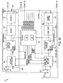
- FIG. 3 is a schematic of a deposition control system 301.
- the exemplary system uses six e-beam guns. However, other numbers of guns may be employed.
- the control system 301 controls the beam current (I_BEAM) supplied to all guns 303 x (I_BEAM x ) used in a process chamber 305 for PVD.
- the amount of beam current (I_BEAM x ) supplied to each gun 303 x depends on the magnitude of the accelerating voltage and filament current (I_FILAMENT x ).
- the chamber 305 vacuum, the properties of the material 307 being evaporated, electrical arcing, and other phenomena which occur inside the chamber 305 during processing all may affect gun 303 x filament current (I_FILAMENT x ).
- I_FILAMENT x gun 303 x filament current
- HV high voltage
- the system 301 uses a thyristor regulator 317 x in the filament current path for each gun 303 x in conjunction with closed-loop feedback as part of the overall control.
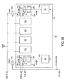
- Each gun 303 x has a dedicated filament regulator system 321 x that includes a beam current regulator 317 x , an SCR controller 323 x , a filament supply 325 x , and a filament rectifier 327 x .
- a processor 329 accepts feedback from the common HV output 339 (HV_FB), individual gun 303 x beam current (V_FB_I_BEAM_GUN x ), and based on a control logic, outputs in response to the feedback signals that control the common HV power supply system 308 and each gun filament regulator system 321 x .
- An HV voltage divider 343 provides a low voltage representation of the HV output 339 as feedback (HV_FB).
- the cathode 331 x is coupled to a negative output of the HV rectifier 315.
- the corresponding positive output of the HV rectifier 315 is coupled to a chamber 305 ground terminal and an accelerating electrode 333 x ground terminal for each gun 303 x .
- When high voltage is applied to each cathode 331 x electrons are emitted and accelerate through the accelerating electrode 333 x forming an electron beam 337 x .
- the deflection coil 335 x rasters the electron beam 337 x over an object 307 for evaporation, or tray (not shown) for heating within in the chamber 305.
- a discussion of raster control is beyond the scope of this disclosure.
- HV_FB The HV feedback
- HV_FB is coupled to the HV regulator 309 and to an HV level comparator 345 input that is part of the processor 329.
- Beam current sensors 347 x produce beam current values (V_FB_I_BEAM_GUN x ) corresponding to each gun 303 x .
- An arc detector 349 which is part of the processor 329 logic monitors the HV level.
- the system may enable beam current regulators of live guns as soon as HV level reaches desired value (e.g., 90% of operating voltage HV).
- An arc detector 349 is used to detect over current conditions which indicate shorting or HV arcing.
- Beam current (V_FB_I_BEAM_GUN x ) is also used as feedback for the beam current regulator 317 x .
- the system compensates for electron beam 337 x perturbations that occur by monitoring the variation of each gun's beam current and voltage.
- the processor 329 analyzes the beam (I_BEAM) (HV_FB) and current (V_FB_I_BEAM_GUN x ) feedback. Processor 329 logic analyzes whether an over current condition exists. The processor 329 controls the common HV power supply system 308 and each gun filament regulator system 321 x .
- the processor 329 reviews a list of permissives regarding possible electrical fault conditions for a determination of system availability (step 515). If no fault conditions are found (step 520), the gun system is ready for operation (step 525).
- the invention turns on the HV regulator 309 (REG_HV_ON) and SCR controller 311 (HV_ON) (step 530) and gradually ramps-up (RAMPING_HV) the HV power supply output 339 via the regulator 309 to the HV level setpoint 341 (step 535).
- a filament on signal (FILAMENT_ON) is output from the processor 329 to SCR controller 323 x and beam regulator 317 x in addition to a beam current regulator 317 x on signal (REG_I_ON x ) (step 535).
- the beam current setpoint is set via potentiometer 353 or from another analog device.
- a comparator 701 compares a desired beam current setpoint 353 against actual beam current feedback (V_FB_I_BEAM_GUNx) and outputs a difference, or error signal.
- the error signal is amplified by a PI (proportional-integral) error amplifier 703.
- An analog adder 705 adds the filament current setpoint 351 to the amplifier 703 output.
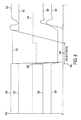
- a control device 711 e.g., an electronic switch outputs a signal in response to the beam regulator signal (REG_I_ON/OFF x ) that modifies the characteristics of the error amplifier 703 during arcing. As soon as arc occurs control device 711 disables the error amplifier 703. In this case output signal of regulator 317 corresponds to I Fil preset (see FIG. 4 )
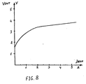
- Filament set point 351 sets initial current value of cathode filament (I Fil preset), that depends upon the preset operating voltage of HV supply (see points A, B FIG.4 ).
- Beam set point 353 sets signal level for Beam current close loop regulator 317 that transmits the command to the input of SCR CONTROLLER 323 that provides control over silicon-controlled rectifiers of Filament Supply 325. From the output of Filament Supply 325 filament, gate voltage is supplied to filament current rectifier 327 that provides control over DC filament current 319 of cathode 331 of gun 303.
- Signal of beam current-sensing device 3A7 of the gun 303 is used as the signal of negative feedback in beam current close loop regulator 317. Beam current value deviation from the preset value causes regulator 317 to generate filament control signal that compensates beam current variation.
Landscapes
- Chemical & Material Sciences (AREA)
- Analytical Chemistry (AREA)
- Physics & Mathematics (AREA)
- Engineering & Computer Science (AREA)
- Plasma & Fusion (AREA)
- Electron Sources, Ion Sources (AREA)
- Physical Vapour Deposition (AREA)
Applications Claiming Priority (1)
| Application Number | Priority Date | Filing Date | Title |
|---|---|---|---|
| US11881208P | 2008-12-01 | 2008-12-01 |
Publications (2)
| Publication Number | Publication Date |
|---|---|
| EP2192607A2 true EP2192607A2 (de) | 2010-06-02 |
| EP2192607A3 EP2192607A3 (de) | 2013-09-04 |
Family
ID=41785832
Family Applications (1)
| Application Number | Title | Priority Date | Filing Date |
|---|---|---|---|
| EP09252707.6A Withdrawn EP2192607A3 (de) | 2008-12-01 | 2009-12-01 | Steuerung des Elektronenstrahlstroms zur Dampfabscheidung |
Country Status (3)
| Country | Link |
|---|---|
| US (1) | US20100263590A1 (de) |
| EP (1) | EP2192607A3 (de) |
| UA (1) | UA112404C2 (de) |
Families Citing this family (3)
| Publication number | Priority date | Publication date | Assignee | Title |
|---|---|---|---|---|
| US10724133B2 (en) * | 2016-09-14 | 2020-07-28 | Raytheon Technologies Corporation | EBPVD columnated vapor stream |
| CN108695128A (zh) * | 2017-04-11 | 2018-10-23 | 上海伟钊光学科技股份有限公司 | 具有束流自动反馈控制的考夫曼离子源 |
| CN111128651A (zh) * | 2018-10-31 | 2020-05-08 | 北京中科信电子装备有限公司 | 一种等离子体淋浴器电源控制方法 |
Family Cites Families (7)
| Publication number | Priority date | Publication date | Assignee | Title |
|---|---|---|---|---|
| SU469163A1 (ru) * | 1968-06-10 | 1975-04-30 | Московский Ордена Ленина Энергетический Институт | Электронно-лучева термическа установка |
| SU490099A1 (ru) * | 1968-07-17 | 1975-10-30 | Московский Ордена Ленина Энергетический Институт | Устройство дл автоматического регулировани электрического режима электротермической установки с электронной пушкой |
| DE2325808C2 (de) * | 1973-05-22 | 1983-07-14 | Leybold-Heraeus GmbH, 5000 Köln | Schaltung zur Regelung der Betriebsparameter eines Elektronenstrahlerzeugers |
| US6590216B1 (en) * | 2000-01-27 | 2003-07-08 | Nikon Corporation | Servo control for high emittance electron source |
| US20050092253A1 (en) * | 2003-11-04 | 2005-05-05 | Venkat Selvamanickam | Tape-manufacturing system having extended operational capabilites |
| DE102005020815B4 (de) * | 2005-05-04 | 2007-05-10 | Applied Materials Gmbh & Co. Kg | Anordnung für die Regelung der Elektronenstrahlleistung einer Elektronenstrahlkanone |
| US20060269812A1 (en) * | 2005-05-27 | 2006-11-30 | Lemkey Franklin D | Process for producing a solid oxide fuel cell and product produced thereby |
-
2009
- 2009-12-01 US US12/628,567 patent/US20100263590A1/en not_active Abandoned
- 2009-12-01 EP EP09252707.6A patent/EP2192607A3/de not_active Withdrawn
- 2009-12-01 UA UAA200912432A patent/UA112404C2/uk unknown
Non-Patent Citations (1)
| Title |
|---|
| None |
Also Published As
| Publication number | Publication date |
|---|---|
| EP2192607A3 (de) | 2013-09-04 |
| US20100263590A1 (en) | 2010-10-21 |
| UA112404C2 (uk) | 2016-09-12 |
Similar Documents
| Publication | Publication Date | Title |
|---|---|---|
| US7014889B2 (en) | Process and apparatus for plasma activated depositions in a vacuum | |
| US5015493A (en) | Process and apparatus for coating conducting pieces using a pulsed glow discharge | |
| KR20090043574A (ko) | 피어스식 전자총의 전자빔 집속 제어방법 및 제어장치 | |
| JP5616426B2 (ja) | 真空処理装置 | |
| US8343591B2 (en) | Method for use with a coating process | |
| JP2010059544A (ja) | 基体を被覆するための被覆装置及び基体を被覆する方法 | |
| EP2192607A2 (de) | Steuerung des Elektronenstrahlstroms zur Dampfabscheidung | |
| Poolcharuansin et al. | Plasma parameters in a pre-ionized HiPIMS discharge operating at low pressure | |
| US5662741A (en) | Process for the ionization of thermally generated material vapors and a device for conducting the process | |
| CN102445901A (zh) | 一种离子源自动稳弧流的方法 | |
| CN103469164B (zh) | 一种实现等离子体激活电子束物理气相沉积的装置和方法 | |
| JP5836027B2 (ja) | イオンプレーティング装置および方法 | |
| JP2001307650A (ja) | イオン源の運転方法およびイオンビーム照射装置 | |
| RU2607398C2 (ru) | Способ нанесения покрытий путем плазменного напыления и устройство для его осуществления | |
| RU173348U1 (ru) | Устройство для нанесения тонкопленочных покрытий | |
| JP4972299B2 (ja) | 電子ビーム蒸着装置、および、当該装置を用いて行う基板の表面への蒸着被膜の形成方法 | |
| RU154033U1 (ru) | Устройство для нанесения тонкопленочных покрытий | |
| US5780803A (en) | Process for the stabilization of plasma generation by means of electron beam vaporizer | |
| JP4980866B2 (ja) | 膜形成装置 | |
| Akan | Operation parameters of the thermionic vacuum arc discharge | |
| JP2014095111A (ja) | 成膜装置及び成膜装置の動作方法 | |
| JPH02125868A (ja) | 電子ビーム蒸着装置 | |
| EP0995215A1 (de) | Leistungsregelvorrichtung für eine ionenquelle mit indirekt geheisster kathode | |
| Chayahara et al. | Metal plasma source for PBII using arc-like discharge with hot cathode | |
| Seitkulov et al. | New Method for Synthesis of Hard Coatings Using Pulsed Bombardment with High-Energy Gas Atoms |
Legal Events
| Date | Code | Title | Description |
|---|---|---|---|
| PUAI | Public reference made under article 153(3) epc to a published international application that has entered the european phase |
Free format text: ORIGINAL CODE: 0009012 |
|
| AK | Designated contracting states |
Kind code of ref document: A2 Designated state(s): AT BE BG CH CY CZ DE DK EE ES FI FR GB GR HR HU IE IS IT LI LT LU LV MC MK MT NL NO PL PT RO SE SI SK SM TR |
|
| AX | Request for extension of the european patent |
Extension state: AL BA RS |
|
| PUAL | Search report despatched |
Free format text: ORIGINAL CODE: 0009013 |
|
| AK | Designated contracting states |
Kind code of ref document: A3 Designated state(s): AT BE BG CH CY CZ DE DK EE ES FI FR GB GR HR HU IE IS IT LI LT LU LV MC MK MT NL NO PL PT RO SE SI SK SM TR |
|
| AX | Request for extension of the european patent |
Extension state: AL BA RS |
|
| RIC1 | Information provided on ipc code assigned before grant |
Ipc: H01J 37/304 20060101AFI20130731BHEP Ipc: H01J 37/305 20060101ALI20130731BHEP |
|
| STAA | Information on the status of an ep patent application or granted ep patent |
Free format text: STATUS: THE APPLICATION IS DEEMED TO BE WITHDRAWN |
|
| 18D | Application deemed to be withdrawn |
Effective date: 20140305 |