EP2192255B1 - Befestigungsvorrichtung für Stulpschiene - Google Patents
Befestigungsvorrichtung für Stulpschiene Download PDFInfo
- Publication number
- EP2192255B1 EP2192255B1 EP20090177189 EP09177189A EP2192255B1 EP 2192255 B1 EP2192255 B1 EP 2192255B1 EP 20090177189 EP20090177189 EP 20090177189 EP 09177189 A EP09177189 A EP 09177189A EP 2192255 B1 EP2192255 B1 EP 2192255B1
- Authority
- EP
- European Patent Office
- Prior art keywords
- free
- legs
- fastening device
- longitudinal
- rigid
- Prior art date
- Legal status (The legal status is an assumption and is not a legal conclusion. Google has not performed a legal analysis and makes no representation as to the accuracy of the status listed.)
- Not-in-force
Links
- 229910052751 metal Inorganic materials 0.000 claims description 31
- 239000002184 metal Substances 0.000 claims description 30
- 238000004873 anchoring Methods 0.000 claims description 18
- 239000004033 plastic Substances 0.000 claims description 7
- 229920003023 plastic Polymers 0.000 claims description 7
- 239000011810 insulating material Substances 0.000 claims description 2
- 230000037361 pathway Effects 0.000 claims 2
- 239000000463 material Substances 0.000 description 6
- 238000009413 insulation Methods 0.000 description 3
- 239000004952 Polyamide Substances 0.000 description 2
- 239000002131 composite material Substances 0.000 description 2
- 239000007769 metal material Substances 0.000 description 2
- 229920002647 polyamide Polymers 0.000 description 2
- 230000002238 attenuated effect Effects 0.000 description 1
- 239000004020 conductor Substances 0.000 description 1
- 230000000994 depressogenic effect Effects 0.000 description 1
- 238000001125 extrusion Methods 0.000 description 1
- 239000000835 fiber Substances 0.000 description 1
- 238000005555 metalworking Methods 0.000 description 1
- 229920000642 polymer Polymers 0.000 description 1
- 239000002861 polymer material Substances 0.000 description 1
- 230000000284 resting effect Effects 0.000 description 1
- 238000000926 separation method Methods 0.000 description 1
- 229910001220 stainless steel Inorganic materials 0.000 description 1
- 239000010935 stainless steel Substances 0.000 description 1
Images
Classifications
-
- E—FIXED CONSTRUCTIONS
- E05—LOCKS; KEYS; WINDOW OR DOOR FITTINGS; SAFES
- E05C—BOLTS OR FASTENING DEVICES FOR WINGS, SPECIALLY FOR DOORS OR WINDOWS
- E05C9/00—Arrangements of simultaneously actuated bolts or other securing devices at well-separated positions on the same wing
- E05C9/004—Faceplates ; Fixing the faceplates to the wing
-
- E—FIXED CONSTRUCTIONS
- E05—LOCKS; KEYS; WINDOW OR DOOR FITTINGS; SAFES
- E05B—LOCKS; ACCESSORIES THEREFOR; HANDCUFFS
- E05B15/00—Other details of locks; Parts for engagement by bolts of fastening devices
- E05B15/16—Use of special materials for parts of locks
- E05B15/1635—Use of special materials for parts of locks of plastics materials
-
- E—FIXED CONSTRUCTIONS
- E05—LOCKS; KEYS; WINDOW OR DOOR FITTINGS; SAFES
- E05B—LOCKS; ACCESSORIES THEREFOR; HANDCUFFS
- E05B17/00—Accessories in connection with locks
- E05B17/0075—Insulating, e.g. for limiting heat transfer; Increasing fire-resistance of locks
-
- E—FIXED CONSTRUCTIONS
- E05—LOCKS; KEYS; WINDOW OR DOOR FITTINGS; SAFES
- E05C—BOLTS OR FASTENING DEVICES FOR WINGS, SPECIALLY FOR DOORS OR WINDOWS
- E05C9/00—Arrangements of simultaneously actuated bolts or other securing devices at well-separated positions on the same wing
- E05C9/02—Arrangements of simultaneously actuated bolts or other securing devices at well-separated positions on the same wing with one sliding bar for fastening when moved in one direction and unfastening when moved in opposite direction; with two sliding bars moved in the same direction when fastening or unfastening
Definitions
- the present invention relates to a fastening device for fixing a headrest on a metalworking jamb.
- the metal joinery have two parallel uprights, one is intended to be articulated while the other has locking elements.
- the latter has a song and two rigid wings extended at a distance from one another projecting from said edge to form a longitudinal free space between said two rigid wings.
- This longitudinal space is intended to receive the locking elements and in particular a lock, bolts and control rods of these bolts.
- the rigid wings each have a free edge and a longitudinal rib which extends substantially parallel to said free edge.
- the longitudinal ribs of said rigid wings extend facing one another within said longitudinal free space.
- the headrest is for example U-shaped and has holes and recesses passage bolts. It is installed on said wings between said free edges to close said longitudinal space and cover in particular the lock, the rods and bolts.
- Known headrest fixing devices comprise screws inserted in the holes, and these screws are screwed into anchoring elements mounted in the bottom of the longitudinal space or through the edge for example. The tightening of the screws makes it possible to maintain in fixed position the headrest against the ribs and between the rigid wings of the upright.
- the documents DE 201 15 354 U1 and EP 0 892 138 B1 disclose, for example, fastening devices devoid of insulating thermal property.
- a problem that arises and that aims to solve the present invention is to provide a fixing device for fixing the headrests easily, and which also allows thermal insulation of the amounts of metal joinery.
- the present invention proposes a fastening device for fixing a headrest on a metal joinery post, said metal joinery post having a singing and two rigid wings extended at a distance. one of the other protruding from said edge to form a longitudinal free space between said two rigid wings, said rigid wings each having a free edge and a longitudinal rib extending substantially parallel to said free edge, the longitudinal ribs of said rigid wings s' extending facing each other within said longitudinal free space, respectively forming a retaining edge oriented away from said free edge, said headrest being intended to be installed on said wings between said free edges to close again said longitudinal space, said fixing device comprising an anchoring element intended to be anchored between said rigid wings and securing means intended to be engaged in said anchor element through said headrest to maintain said headrest against said rigid wings.
- said anchoring element comprises a profiled U-shaped piece made of a thermally insulating material and having two flexible wings substantially parallel to each other, said U-shaped piece having a shoulder forming two substantially parallel bearing surfaces respectively on the opposite faces of said flexible wings; and said wings are movable between a position close to one another in which said anchoring element is able to be engaged between said ribs and a position spaced apart from each other in which said bearing spans come from respectively engaged on said retaining edges of said ribs.
- a feature of the invention lies in the implementation of a thermally insulating U shaped profile piece, relative to metallic materials, and which engages in the ribs without transmitting heat. from one rigid wing to the other. In this way, when the two sections extended respectively by their rigid wing and which form the amount of woodwork, are isolated from each other at the edge, there is then no thermal bridge or between the two wings neither between the two sections. In this way, the thermal insulation at the level of the amount is ensured.
- said U-shaped piece has a bottom and a median receiving portion of said securing means integral with said bottom and extending between said flexible wings.
- said median receiving portion preferably has an orifice substantially perpendicular to said bearing surfaces, said orifice being intended to receive said securing means. Also, these are intended, on one side to be locked through said orifice, inside the middle part, and on the other side, to come to apply on the headrest they cross, to maintain the latter in force support against the ribs for example.
- said profiled U-shaped piece has two paths of passage respectively between said flexible wings and said middle part, said passageways extending substantially parallel to said bearing surfaces, so as to make it possible to house the or the control rods of the bolts precisely, between the headrest and the U-shaped piece.
- said U-shaped piece is molded in one piece of plastics material. It is for example obtained by extrusion and then by cutting in section. Thus, it is performed at an advantageous cost.
- the plastic material for example a polymer of the polyamide type
- the wings are elastically flexible. In this way, when the U-shaped piece is engaged between the ribs, the flexible wings are then brought closer to one another by force and as soon as the piece is in position and the flexible wings are released, they return to their position. original position, separated from each other so that the bearing spans engage against the retaining edges of these ribs. This feature allows a quick and easy mounting of the U-shaped piece, as will be explained in more detail below.
- said profiled U-shaped piece advantageously has a groove extending in said bottom substantially parallel to said flexible flanges, said groove opening at the opposite of said middle portion, so as to reduce the resistance to approaching the two flexible flanges. towards each other when the U-shaped piece is engaged between the ribs.
- said flexible wings respectively have a free edge, and said securing means are engaged in said anchoring element, between said free edges.
- said opposite faces of said flexible wings have inclined walls forming ramps, opposite said free edges with respect to said bearing surfaces, so as to engage the U-shaped piece so that the inclined walls come resting between the ribs and then pushing the U-shaped piece towards the edge so that the inclined walls are driven in friction against the ribs, and tend to move towards one another of the flexible wings.
- the flexible wings are resiliently biased and move away from each other so that the bearing surfaces are opposite the retaining edges of the ribs.
- the profiled U-shaped piece is likely to be pre-assembled with the headrest and the securing means, and then to be clipped between the rigid wings, which greatly facilitates the mounting of the headrest.
- said securing means comprise screw elements capable of being screwed into said profiled U-shaped piece, it is sufficient then after clipping, to screw the screwable elements and then, the latter bear on the headrest while the U-shaped piece engages the retaining edges of the ribs.
- the headrest is gripped between the securing means and the rigid wings on which it is supported.
- the headrest is U-shaped, and the wings of the headrest bear against the edges of the ribs opposite the retaining edge.
- the present invention relates to an amount of metal joinery equipped with a headrest, said amount having a singing and two rigid wings extended at a distance from one another projecting from said edge to form a longitudinal free space between said two rigid wings, said rigid wings each having a free edge and a longitudinal rib extending substantially parallel to said free edge, the longitudinal ribs of said rigid wings extending facing one another within said longitudinal free space, respectively forming a retaining edge oriented away from said free edge, said headrest being intended to be installed on said wings between said free edges to close said longitudinal space;
- the amount of metal joinery comprises a fixing device as defined above according to the first object.
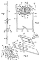
- the Figure 1 illustrates in profile view, a lock mechanism including a housing 10, a shooting headrest 12 applied to the edge of the housing 10 and four bolts, a latch bolt 14, a dead bolt 16, a low bolt 18 and a high bolt 20.
- a lock mechanism including a housing 10, a shooting headrest 12 applied to the edge of the housing 10 and four bolts, a latch bolt 14, a dead bolt 16, a low bolt 18 and a high bolt 20.
- the amount of metal joinery 22 inside which are installed all the aforementioned elements.
- the amount of metal joinery 22 consists of two metal profiles facing each other, an external metal section 24 and an internal metal section 26.
- the two metal sections 24, 26 are held in a fixed position relative to each other by means of of two longitudinal profiles of composite material, one 28 forming with the respective returns 30, 32 external metal profiles 24 and inner 26, one edge 34 of the amount of metal joinery 22, the other 36 to the opposite, closing the amount of metal joinery 22.
- These two longitudinal profiles 28, 36 of composite material for example a fiber-filled polymer material, can break the heat conduction between the two outer metal profiles 24 and inner 26.
- the amount of metal joinery 22 has two rigid wings 38, 40 which extend at a distance from each other and parallel to each other, projecting from the edge 34.
- These two rigid wings 38, 40 respectively extend the external metal section 24 and the internal metal section 26 and they define a longitudinal free space 42. They also have respectively a free edge 44, 46 and a rib 48, 50 which extend respectively projecting from the rigid wings 38, 40 and facing each other within the longitudinal free space 42 and parallel to the free edges 44, 46.
- These ribs 48, 50 respectively have a retaining edge 52, 54 oriented towards the edge 34 and the opposite an applied edge 56, 58 oriented towards the outside of the longitudinal free space 42.
- a fixing device 60 of a U-shaped headrest 62 Between the rigid wings is installed a fixing device 60 of a U-shaped headrest 62, and between the U-shaped headrest 62 and the fixing device 60, is slidably mounted a rod 63 which will be described in more detail with reference to the Figure 3 .
- This rod makes it possible to actuate the top and bottom bolts 18 by means of the lock included in the casing 10 shown in FIG. Figure 1 .
- the fixing device 60 according to the invention.
- the profiled U-shaped headrest 62 and the fixing device comprising, on the one hand, an anchoring element 64 and, on the other hand, a fixing screw 66.
- the anchoring element 64 comprises a U-shaped piece having an axial plane of symmetry P and an axis of symmetry A included in said plane, said part being made from a section of a plastic profile, by polyamide example, and it has two flexible wings 68, 70 opposite to each other and parallel to each other. These two flexible wings 68, 70 are interconnected by a bottom 72 opposite to the open part of the U-shaped piece.
- the bottom 72 has a median receiving portion 74 which extends inside the the profiled piece U and projecting from said bottom 72, between the two flexible wings 68, 70.
- the two flexible wings 68, 70 extend parallel to the plane of symmetry P, from the bottom 72 to a free end 80, 81.
- the flexible wings have two opposite faces 76, 78, while the U shaped profile has, midway between the bottom 72 and the free ends 80, 81, a shoulder providing two opposite bearing surfaces 82, 84.
- the two opposite faces 76, 78 respectively have an inclined wall 86, 88 with respect to the plane of axial symmetry P, between the respective bearing surfaces 82, 84 and the base 72.
- this anchoring element 64 has a small width at the bottom 72, substantially less than the distance separating the two ribs 48, 50 mentioned above, and it flares up to the support bearing surfaces 82, 84.
- the bottom 72 and the median receiving portion 64 has an axial groove 90 cut symmetrically by the plane of symmetry P and which precisely opens into the bottom portion 72 and extends partially in the median receiving portion 64.
- the latter also has a central thread 92 perpendicular to the axis of symmetry A of the anchoring element 64 and which has, at one of its ends, an intersection with the axial groove 90, and the other of its ends, opposite the bottom 72, an opening which opens at the free ends 80, 81 of the flexible wings 68, 70.
- the profiled U-shaped piece has two axial parallel grooves 94, 96 respectively between the flexible wings 68, 70 and the median receiving portion 74.
- These axial parallel grooves 94, 96 constitute two parallel passage paths on both sides. other of the median receiving portion 74 and at the edges 87, 89.
- the Figure 3 further illustrates the rod 63 in which is formed an oblong recess 98 central extending longitudinally defining then two opposite parts of the rod 100, 102 able to be slidably mounted respectively in the axial parallel grooves 94, 96.
- the profiled U-shaped headrest 62 capable of capping the free ends 80, 81 of the flexible wings 68, 70 and whose headrests are intended to come respectively in sliding abutment on the opposite free edges 87, 89.
- the U-shaped headrest 62 has an orifice 104 adapted to receive the fastening screw 66 to then pass through the oblong recess 98 and be screwed through the central thread 92.
- the assembly consisting of the U-shaped piece, the rod 63, the headrest 62 and the fixing screw 66 not completely screwed inside the central thread 92, can be clipped between the rigid flanges 38 , 40 of the amount of metal joinery 22 as shown on the Figure 2 .
- it just first apply the aforementioned set between the rigid wings 38, 40 and more specifically, the inclined walls 86, 88 respectively between the ribs 50, 48 and on which they come to bear.
- the inclined walls 86, 88 ramp forms and as the depression, the flexible wings 68, 70 are closer to each other.
- the flexible wings 68, 70 are authorized because on the one hand, there is a free space between the flexible wings 68, 70 and the median receiving portion 74 and secondly there is one also delimited by the groove 90.
- the approximation of the wings flexible 68, 70 is it easier.
- the flexible wings 68, 70 come closer to each other by deforming elastically, while the aforementioned free spaces shrink, and as soon as the shoulder reaches a level located in below the ribs 50, 48, towards the edge 34, the flexible wings 68, 70 deviate then abruptly to find their initial position and thus, the bearing surfaces 82, 84 respectively come opposite the retaining edges 52, 54 ribs 48, 50.
- the wings of the U-shaped headrest 62 are respectively applied to the edge of the wall 56, 58 of the ribs 48, 50. Then, the fixing screw 66 which is screwed more completely into the central thread 92 then causes concomitantly, the depression of the U-shaped piece in the profiled U-shaped headrest 62 and the engagement of the bearing surfaces 82, 84 against the retaining edge 52, 54, and tends to substantially deform the middle receiving portion 74 and the bottom 72 and thus, to cause the separation even more flexible wings 68, 70.
- the edges of the flanges of the U-shaped headrest 62 applied respectively to the edges of applied 56, 58 are forced against these edges of the applique.
- the wings of the profiled U-shaped headrest 62 and the bearing surfaces 82, 84 respectively form a vice and grip respectively ribs 48, 50.
- the force clamping of the fastening screw 66 allows in this way to maintain in position fixed, through the ribs 48, 50, the U-shaped headrest 62 and the anchoring element comprising the U-shaped piece.
- connection between the rigid wings 38, 40 is achieved by means of the ribs 48, 50 only by the profiled U-shaped headrest 62 which is made of a thermally insulating plastic material, and by the U-profile piece 64, also made of a thermally insulating plastic material. Also, the heat transfer by conduction between the outer metal section 24 the inner metal section 26 is considerably attenuated.
- Fastening devices as defined above are installed gradually between the rigid wings 38, 40, for example six in number, over the entire length of the amount of the metal joinery 22.
- the present invention also relates to an amount of metal joinery equipped with a headrest and a fixing device as defined above according to the first object.
Landscapes
- Engineering & Computer Science (AREA)
- Mechanical Engineering (AREA)
- Chair Legs, Seat Parts, And Backrests (AREA)
Claims (10)
- Befestigungsvorrichtung zum Befestigen einer Stulpschiene (62) an einer Stütze für eine Metallbaukonstruktion (22), wobei die Stütze für eine Metallbaukonstruktion eine Kante (34) und zwei starre Flügel (38, 40) aufweist, die in einem Abstand zueinander verlaufen und von der Kante vorspringen, um einen Längsfreiraum (42) zwischen den beiden starren Flügeln zu bilden, wobei die starren Flügel jeweils einen freien Rand (44, 46) und eine Längsrippe (48, 50) aufweisen, die im Wesentlichen parallel zu dem freien Rand verläuft, wobei die Längsrippen der starren Flügel einander gegenüber im Inneren des Längsfreiraums (42) verlaufen und dabei jeweils einen Befestigungsrand (52, 54) bilden, der gegenüber dem feien Rand (44, 46) ausgerichtet ist, wobei die Stulpschiene dafür bestimmt ist, an den starren Flügeln (38, 40) zwischen den freien Rändern angebracht zu werden, um den längs verlaufenden Raum (42) zu schließen, wobei die Befestigungsvorrichtung ein Verankerungselement (64) umfasst, das dafür bestimmt ist, zwischen den starren Flügeln verankert zu werden, und Verbindungsmittel (66), die dafür bestimmt sind, in das Verankerungselement (64) gesteckt zu werden und dabei die Stulpschiene zu durchqueren, um die Stulpschiene an den starren Flügeln zu halten,
dadurch gekennzeichnet, dass das Verankerungselement ein U-Profilteil aus einem wärmeisolierenden Material umfasst, das zwei flexible Flügel (68, 70) aufweist, die im Wesentlichen parallel zueinander verlaufen, wobei das U-Profilteil einen Vorsprung aufweist, der zwei im Wesentlichen parallele Auflageflächen (82, 84) jeweils auf den gegenüberliegenden Seiten (76, 78) der flexiblen Flügel bildet,
und dadurch, dass die flexiblen Flügel (68, 70) zwischen einer einander angenäherten Position, in der das Verankerungselement (64) zwischen die Rippen (48, 50) geführt werden kann, und einer voneinander entfernten Position beweglich sind, in der die Auflageflächen (82, 84) jeweils an den Befestigungsrändern (52, 54) der Rippen eingreifen. - Befestigungsvorrichtung nach Anspruch 1, dadurch gekennzeichnet, dass das U-Profilteil (64) einen Boden (72) und einen mittleren Aufnahmeabschnitt (74) für die Verbindungsmittel (66) aufweist, der eine Einheit mit dem Boden bildet und zwischen den flexiblen Flügeln (68, 70) verläuft.
- Befestigungsvorrichtung nach Anspruch 2, dadurch gekennzeichnet, dass der mittlere Aufnahmeabschnitt (74) eine Öffnung (92) im Wesentlichen senkrecht zu den Auflageflächen (82, 84) aufweist, wobei die Öffnung dafür bestimmt ist, die Verbindungsmittel (66) aufzunehmen.
- Befestigungsvorrichtung nach Anspruch 2 oder 3, dadurch gekennzeichnet, dass das U-Profilteil zwei Durchgangskanäle (94, 96) jeweils zwischen den flexiblen Flügeln (68, 70) und dem mittleren Abschnitt (74) aufweist, wobei die Durchgangskanäle im Wesentlichen parallel zu den Auflageflächen (82, 84) verlaufen.
- Befestigungsvorrichtung nach einem der Ansprüche 1 bis 4, dadurch gekennzeichnet, dass das U-Profilteil aus einem einzigen Stück Kunststoff geformt ist.
- Befestigungsvorrichtung nach Anspruch 2 und 5, dadurch gekennzeichnet, dass das U-Profilteil eine Rille (90) aufweist, die in dem Boden (72) im Wesentlichen parallel zu den flexiblen Flügeln (68, 70) verläuft, wobei die Rille gegenüber dem mittleren Abschnitt (74) ausläuft.
- Befestigungsvorrichtung nach einem der Ansprüche 1 bis 6, dadurch gekennzeichnet, dass die flexiblen Flügel (68, 70) jeweils eine freie Kante (87, 89) aufweisen und dadurch, dass die Verbindungsmittel (66) zwischen den freien Kanten in das Verankerungselement gesteckt sind.
- Befestigungsvorrichtung nach Anspruch 7, dadurch gekennzeichnet, dass die gegenüberliegenden Seiten der flexiblen Flügel (68, 70) gegenüber den freien Kanten (87, 89) bezogen auf die Auflageflächen (82, 84) geneigte Wände (86, 88), die Schrägen bilden, aufweisen.
- Befestigungsvorrichtung nach einem der Ansprüche 1 bis 8, dadurch gekennzeichnet, dass die Verbindungsmittel (66) schraubbare Elemente aufweisen, die in das U-Profilteil geschraubt werden können.
- Stütze für eine Metallbaukonstruktion (22), die mit einer Stulpschiene (62) versehen ist, wobei die Stütze eine Kante (34) und zwei starre Flügel (38, 40) aufweist, die in einem Abstand zueinander verlaufen und von der Kante vorspringen, um einen Längsfreiraum (42) zwischen den beiden starren Flügeln zu bilden, wobei die starren Flügel jeweils einen freien Rand (44, 46) und eine Längsrippe (48, 50) aufweisen, die im Wesentlichen parallel zu dem freien Rand verläuft, wobei die Längsrippen der starren Flügel einander gegenüber im Inneren des Längsfreiraums (42) verlaufen und dabei jeweils einen Befestigungsrand (52, 54) bilden, der gegenüber dem feien Rand ausgerichtet ist, wobei die Stulpschiene dafür bestimmt ist, an den starren Flügeln (38, 40) zwischen den freien Rändern angebracht zu werden, um den längs verlaufenden Raum zu schließen,
dadurch gekennzeichnet, dass sie eine Befestigungsvorrichtung nach einem der Ansprüche 1 bis 9 zum Befestigen der Stulpschiene (62) an der Stütze für eine Metallbaukonstruktion (22) umfasst.
Applications Claiming Priority (1)
| Application Number | Priority Date | Filing Date | Title |
|---|---|---|---|
| FR0806674A FR2938888B1 (fr) | 2008-11-27 | 2008-11-27 | Dispositif de fixation de tetiere. |
Publications (2)
| Publication Number | Publication Date |
|---|---|
| EP2192255A1 EP2192255A1 (de) | 2010-06-02 |
| EP2192255B1 true EP2192255B1 (de) | 2012-08-15 |
Family
ID=40786451
Family Applications (1)
| Application Number | Title | Priority Date | Filing Date |
|---|---|---|---|
| EP20090177189 Not-in-force EP2192255B1 (de) | 2008-11-27 | 2009-11-26 | Befestigungsvorrichtung für Stulpschiene |
Country Status (2)
| Country | Link |
|---|---|
| EP (1) | EP2192255B1 (de) |
| FR (1) | FR2938888B1 (de) |
Families Citing this family (2)
| Publication number | Priority date | Publication date | Assignee | Title |
|---|---|---|---|---|
| DE102010062309A1 (de) * | 2010-12-01 | 2012-06-21 | Aug. Winkhaus Gmbh & Co. Kg | Befestigungseinrichtung einer Stulpschiene eines Treibstangenbeschlages |
| US12163361B2 (en) * | 2020-03-17 | 2024-12-10 | Truth Hardware Corporation | Roll-form tie bar and guide for casement window |
Family Cites Families (4)
| Publication number | Priority date | Publication date | Assignee | Title |
|---|---|---|---|---|
| DE3101393A1 (de) * | 1981-01-17 | 1982-09-02 | SCHÜCO Heinz Schürmann GmbH & Co, 4800 Bielefeld | "mit einem stulpschienenbeschlag ausgeruesteter tuer- oder fensterfluegel" |
| DE19730600A1 (de) * | 1997-07-17 | 1999-01-21 | Siegenia Frank Kg | Stulpschienenbeschlag |
| DE20115354U1 (de) * | 2001-09-18 | 2001-11-15 | Aug. Winkhaus GmbH & Co. KG, 48291 Telgte | Beschlagteil für einen Treibstangenbeschlag |
| DE10345758B4 (de) * | 2003-10-01 | 2010-09-23 | Wicona Bausysteme Gmbh | Beschlag für den Flügelrahmen eines Fensters, einer Tür oder dergleichen |
-
2008
- 2008-11-27 FR FR0806674A patent/FR2938888B1/fr not_active Expired - Fee Related
-
2009
- 2009-11-26 EP EP20090177189 patent/EP2192255B1/de not_active Not-in-force
Also Published As
| Publication number | Publication date |
|---|---|
| FR2938888B1 (fr) | 2010-12-10 |
| FR2938888A1 (fr) | 2010-05-28 |
| EP2192255A1 (de) | 2010-06-02 |
Similar Documents
| Publication | Publication Date | Title |
|---|---|---|
| FR2983895A1 (fr) | Barriere a profiles rigides et profiles d'habillage | |
| EP2192255B1 (de) | Befestigungsvorrichtung für Stulpschiene | |
| FR3000120A1 (fr) | Cale de rupture thermique et electrolytique pour equerre de fixation murale d’un panneau de parement | |
| EP3263813B1 (de) | Befestigungsvorrichtung eines beschlags in einem t-förmigen rahmenfalz | |
| EP0851551B1 (de) | Verfahren und Vorrichtung zum Verbessern des Haltens eines Zubehörs mit Schnappbefestigung an einem Kabelrinnensockel | |
| CA2696422A1 (fr) | Connecteur pour raccorder deux extremites creuses de profile | |
| EP1094695B1 (de) | Pfosten für ein Metallgerippe, insbesondere für ein Rahmengestell eines Schaltschrankes | |
| FR3043111B1 (fr) | Dispositif d'entretoisement pour le doublage d'une structure | |
| BE1017940A3 (fr) | Ensemble et procede pour la pose d'un vitrage dans un chassis. | |
| EP2189599B1 (de) | Stulpschiene für ein Schloss, Schloss mit Stulpschiene und Schiebetür mir einem solchen Schloss | |
| FR2944825A1 (fr) | Dispositif de fixation de ferrure notamment pour fenetres en aluminium ou matiere plastique, ferrure et vantail ou cadre dormant equipes. | |
| FR2709528A1 (fr) | Dispositif de support de câbles ou conduits. | |
| EP1847675A1 (de) | Anschluss zur Verbindung von zwei hohlen Profilenden | |
| FR2585756A1 (fr) | Dispositif de jonction entre boitier et prolongateur de cremone a tetiere et a tringles | |
| FR3026120B1 (fr) | Dispositif de pose du type papillon | |
| FR2964718A1 (fr) | Dispositif de fixation d'un raccord pour conduite de transport de fluide sur une cloison | |
| EP1614849A2 (de) | Vorrichtung zum Befestigen und Verbinden von Glasleisten | |
| EP2251554B1 (de) | Vorrichtung zur Befestigung zwischen einer Handkurbelstange eines Rollladens und einem Drehorgan am Ausgang des Rollladenkastens oder an der Handkurbel | |
| EP2099000B1 (de) | Aufbewahrungsgehäuse mit Schnellbefestigung | |
| FR2932518A1 (fr) | Dispositif de verrouillage comportant une tetiere et une piece d'isolation thermique de la tetiere. | |
| FR2930606A1 (fr) | Dispositif de raccordement d'elements tubulaires | |
| FR2805882A1 (fr) | Profile composite formant au moins une feuillure susceptible d'accueillir la bordure de panneaux divers, d'epaisseur differente | |
| EP4438911A1 (de) | Befestigungssystem an einem gewindebolzen | |
| EP2182127A1 (de) | Struktur mit einer ersten und einer zweiten Wand, im wesentlichen wagerecht und voneinander beabstandet | |
| EP1985791B1 (de) | Lamelle aus Metall für Rolläden oder Sektionaltore |
Legal Events
| Date | Code | Title | Description |
|---|---|---|---|
| PUAI | Public reference made under article 153(3) epc to a published international application that has entered the european phase |
Free format text: ORIGINAL CODE: 0009012 |
|
| AK | Designated contracting states |
Kind code of ref document: A1 Designated state(s): AT BE BG CH CY CZ DE DK EE ES FI FR GB GR HR HU IE IS IT LI LT LU LV MC MK MT NL NO PL PT RO SE SI SK SM TR |
|
| AX | Request for extension of the european patent |
Extension state: AL BA RS |
|
| 17P | Request for examination filed |
Effective date: 20101202 |
|
| 17Q | First examination report despatched |
Effective date: 20110125 |
|
| RIC1 | Information provided on ipc code assigned before grant |
Ipc: E05C 9/02 20060101ALN20111222BHEP Ipc: E05C 9/00 20060101AFI20111222BHEP |
|
| GRAP | Despatch of communication of intention to grant a patent |
Free format text: ORIGINAL CODE: EPIDOSNIGR1 |
|
| RIC1 | Information provided on ipc code assigned before grant |
Ipc: E05C 9/00 20060101AFI20120112BHEP Ipc: E05C 9/02 20060101ALN20120112BHEP |
|
| GRAS | Grant fee paid |
Free format text: ORIGINAL CODE: EPIDOSNIGR3 |
|
| GRAA | (expected) grant |
Free format text: ORIGINAL CODE: 0009210 |
|
| AK | Designated contracting states |
Kind code of ref document: B1 Designated state(s): AT BE BG CH CY CZ DE DK EE ES FI FR GB GR HR HU IE IS IT LI LT LU LV MC MK MT NL NO PL PT RO SE SI SK SM TR |
|
| REG | Reference to a national code |
Ref country code: AT Ref legal event code: REF Ref document number: 570950 Country of ref document: AT Kind code of ref document: T Effective date: 20120815 Ref country code: GB Ref legal event code: FG4D Free format text: NOT ENGLISH Ref country code: CH Ref legal event code: EP |
|
| REG | Reference to a national code |
Ref country code: IE Ref legal event code: FG4D Free format text: LANGUAGE OF EP DOCUMENT: FRENCH |
|
| REG | Reference to a national code |
Ref country code: DE Ref legal event code: R096 Ref document number: 602009008956 Country of ref document: DE Effective date: 20121011 |
|
| REG | Reference to a national code |
Ref country code: NL Ref legal event code: VDEP Effective date: 20120815 |
|
| REG | Reference to a national code |
Ref country code: AT Ref legal event code: MK05 Ref document number: 570950 Country of ref document: AT Kind code of ref document: T Effective date: 20120815 |
|
| PG25 | Lapsed in a contracting state [announced via postgrant information from national office to epo] |
Ref country code: AT Free format text: LAPSE BECAUSE OF FAILURE TO SUBMIT A TRANSLATION OF THE DESCRIPTION OR TO PAY THE FEE WITHIN THE PRESCRIBED TIME-LIMIT Effective date: 20120815 Ref country code: FI Free format text: LAPSE BECAUSE OF FAILURE TO SUBMIT A TRANSLATION OF THE DESCRIPTION OR TO PAY THE FEE WITHIN THE PRESCRIBED TIME-LIMIT Effective date: 20120815 Ref country code: LT Free format text: LAPSE BECAUSE OF FAILURE TO SUBMIT A TRANSLATION OF THE DESCRIPTION OR TO PAY THE FEE WITHIN THE PRESCRIBED TIME-LIMIT Effective date: 20120815 Ref country code: HR Free format text: LAPSE BECAUSE OF FAILURE TO SUBMIT A TRANSLATION OF THE DESCRIPTION OR TO PAY THE FEE WITHIN THE PRESCRIBED TIME-LIMIT Effective date: 20120815 Ref country code: IS Free format text: LAPSE BECAUSE OF FAILURE TO SUBMIT A TRANSLATION OF THE DESCRIPTION OR TO PAY THE FEE WITHIN THE PRESCRIBED TIME-LIMIT Effective date: 20121215 Ref country code: CY Free format text: LAPSE BECAUSE OF FAILURE TO SUBMIT A TRANSLATION OF THE DESCRIPTION OR TO PAY THE FEE WITHIN THE PRESCRIBED TIME-LIMIT Effective date: 20120815 Ref country code: NO Free format text: LAPSE BECAUSE OF FAILURE TO SUBMIT A TRANSLATION OF THE DESCRIPTION OR TO PAY THE FEE WITHIN THE PRESCRIBED TIME-LIMIT Effective date: 20121115 |
|
| PG25 | Lapsed in a contracting state [announced via postgrant information from national office to epo] |
Ref country code: SE Free format text: LAPSE BECAUSE OF FAILURE TO SUBMIT A TRANSLATION OF THE DESCRIPTION OR TO PAY THE FEE WITHIN THE PRESCRIBED TIME-LIMIT Effective date: 20120815 Ref country code: SI Free format text: LAPSE BECAUSE OF FAILURE TO SUBMIT A TRANSLATION OF THE DESCRIPTION OR TO PAY THE FEE WITHIN THE PRESCRIBED TIME-LIMIT Effective date: 20120815 Ref country code: GR Free format text: LAPSE BECAUSE OF FAILURE TO SUBMIT A TRANSLATION OF THE DESCRIPTION OR TO PAY THE FEE WITHIN THE PRESCRIBED TIME-LIMIT Effective date: 20121116 Ref country code: PL Free format text: LAPSE BECAUSE OF FAILURE TO SUBMIT A TRANSLATION OF THE DESCRIPTION OR TO PAY THE FEE WITHIN THE PRESCRIBED TIME-LIMIT Effective date: 20120815 Ref country code: LV Free format text: LAPSE BECAUSE OF FAILURE TO SUBMIT A TRANSLATION OF THE DESCRIPTION OR TO PAY THE FEE WITHIN THE PRESCRIBED TIME-LIMIT Effective date: 20120815 Ref country code: PT Free format text: LAPSE BECAUSE OF FAILURE TO SUBMIT A TRANSLATION OF THE DESCRIPTION OR TO PAY THE FEE WITHIN THE PRESCRIBED TIME-LIMIT Effective date: 20121217 |
|
| PG25 | Lapsed in a contracting state [announced via postgrant information from national office to epo] |
Ref country code: NL Free format text: LAPSE BECAUSE OF FAILURE TO SUBMIT A TRANSLATION OF THE DESCRIPTION OR TO PAY THE FEE WITHIN THE PRESCRIBED TIME-LIMIT Effective date: 20120815 |
|
| PG25 | Lapsed in a contracting state [announced via postgrant information from national office to epo] |
Ref country code: RO Free format text: LAPSE BECAUSE OF FAILURE TO SUBMIT A TRANSLATION OF THE DESCRIPTION OR TO PAY THE FEE WITHIN THE PRESCRIBED TIME-LIMIT Effective date: 20120815 Ref country code: EE Free format text: LAPSE BECAUSE OF FAILURE TO SUBMIT A TRANSLATION OF THE DESCRIPTION OR TO PAY THE FEE WITHIN THE PRESCRIBED TIME-LIMIT Effective date: 20120815 Ref country code: CZ Free format text: LAPSE BECAUSE OF FAILURE TO SUBMIT A TRANSLATION OF THE DESCRIPTION OR TO PAY THE FEE WITHIN THE PRESCRIBED TIME-LIMIT Effective date: 20120815 Ref country code: ES Free format text: LAPSE BECAUSE OF FAILURE TO SUBMIT A TRANSLATION OF THE DESCRIPTION OR TO PAY THE FEE WITHIN THE PRESCRIBED TIME-LIMIT Effective date: 20121126 Ref country code: DK Free format text: LAPSE BECAUSE OF FAILURE TO SUBMIT A TRANSLATION OF THE DESCRIPTION OR TO PAY THE FEE WITHIN THE PRESCRIBED TIME-LIMIT Effective date: 20120815 |
|
| PG25 | Lapsed in a contracting state [announced via postgrant information from national office to epo] |
Ref country code: IT Free format text: LAPSE BECAUSE OF FAILURE TO SUBMIT A TRANSLATION OF THE DESCRIPTION OR TO PAY THE FEE WITHIN THE PRESCRIBED TIME-LIMIT Effective date: 20120815 Ref country code: SK Free format text: LAPSE BECAUSE OF FAILURE TO SUBMIT A TRANSLATION OF THE DESCRIPTION OR TO PAY THE FEE WITHIN THE PRESCRIBED TIME-LIMIT Effective date: 20120815 |
|
| PLBE | No opposition filed within time limit |
Free format text: ORIGINAL CODE: 0009261 |
|
| STAA | Information on the status of an ep patent application or granted ep patent |
Free format text: STATUS: NO OPPOSITION FILED WITHIN TIME LIMIT |
|
| 26N | No opposition filed |
Effective date: 20130516 |
|
| PG25 | Lapsed in a contracting state [announced via postgrant information from national office to epo] |
Ref country code: BG Free format text: LAPSE BECAUSE OF FAILURE TO SUBMIT A TRANSLATION OF THE DESCRIPTION OR TO PAY THE FEE WITHIN THE PRESCRIBED TIME-LIMIT Effective date: 20121115 |
|
| REG | Reference to a national code |
Ref country code: IE Ref legal event code: MM4A |
|
| REG | Reference to a national code |
Ref country code: DE Ref legal event code: R097 Ref document number: 602009008956 Country of ref document: DE Effective date: 20130516 |
|
| PG25 | Lapsed in a contracting state [announced via postgrant information from national office to epo] |
Ref country code: IE Free format text: LAPSE BECAUSE OF NON-PAYMENT OF DUE FEES Effective date: 20121126 |
|
| PG25 | Lapsed in a contracting state [announced via postgrant information from national office to epo] |
Ref country code: MT Free format text: LAPSE BECAUSE OF FAILURE TO SUBMIT A TRANSLATION OF THE DESCRIPTION OR TO PAY THE FEE WITHIN THE PRESCRIBED TIME-LIMIT Effective date: 20120815 |
|
| REG | Reference to a national code |
Ref country code: FR Ref legal event code: CD Owner name: DOM-METALUX, FR Effective date: 20140305 |
|
| PG25 | Lapsed in a contracting state [announced via postgrant information from national office to epo] |
Ref country code: TR Free format text: LAPSE BECAUSE OF FAILURE TO SUBMIT A TRANSLATION OF THE DESCRIPTION OR TO PAY THE FEE WITHIN THE PRESCRIBED TIME-LIMIT Effective date: 20120815 |
|
| PG25 | Lapsed in a contracting state [announced via postgrant information from national office to epo] |
Ref country code: SM Free format text: LAPSE BECAUSE OF FAILURE TO SUBMIT A TRANSLATION OF THE DESCRIPTION OR TO PAY THE FEE WITHIN THE PRESCRIBED TIME-LIMIT Effective date: 20120815 |
|
| PG25 | Lapsed in a contracting state [announced via postgrant information from national office to epo] |
Ref country code: HU Free format text: LAPSE BECAUSE OF FAILURE TO SUBMIT A TRANSLATION OF THE DESCRIPTION OR TO PAY THE FEE WITHIN THE PRESCRIBED TIME-LIMIT Effective date: 20091126 |
|
| PG25 | Lapsed in a contracting state [announced via postgrant information from national office to epo] |
Ref country code: MK Free format text: LAPSE BECAUSE OF FAILURE TO SUBMIT A TRANSLATION OF THE DESCRIPTION OR TO PAY THE FEE WITHIN THE PRESCRIBED TIME-LIMIT Effective date: 20120815 |
|
| REG | Reference to a national code |
Ref country code: FR Ref legal event code: PLFP Year of fee payment: 7 |
|
| REG | Reference to a national code |
Ref country code: FR Ref legal event code: PLFP Year of fee payment: 8 |
|
| PGFP | Annual fee paid to national office [announced via postgrant information from national office to epo] |
Ref country code: MC Payment date: 20161129 Year of fee payment: 8 Ref country code: DE Payment date: 20161129 Year of fee payment: 8 Ref country code: LU Payment date: 20161206 Year of fee payment: 8 Ref country code: GB Payment date: 20161129 Year of fee payment: 8 Ref country code: CH Payment date: 20161221 Year of fee payment: 8 |
|
| PGFP | Annual fee paid to national office [announced via postgrant information from national office to epo] |
Ref country code: BE Payment date: 20161129 Year of fee payment: 8 |
|
| REG | Reference to a national code |
Ref country code: FR Ref legal event code: PLFP Year of fee payment: 9 |
|
| PGFP | Annual fee paid to national office [announced via postgrant information from national office to epo] |
Ref country code: FR Payment date: 20171113 Year of fee payment: 9 |
|
| REG | Reference to a national code |
Ref country code: DE Ref legal event code: R119 Ref document number: 602009008956 Country of ref document: DE |
|
| PG25 | Lapsed in a contracting state [announced via postgrant information from national office to epo] |
Ref country code: MC Free format text: LAPSE BECAUSE OF NON-PAYMENT OF DUE FEES Effective date: 20171130 |
|
| GBPC | Gb: european patent ceased through non-payment of renewal fee |
Effective date: 20171126 |
|
| PG25 | Lapsed in a contracting state [announced via postgrant information from national office to epo] |
Ref country code: CH Free format text: LAPSE BECAUSE OF NON-PAYMENT OF DUE FEES Effective date: 20171130 Ref country code: LI Free format text: LAPSE BECAUSE OF NON-PAYMENT OF DUE FEES Effective date: 20171130 |
|
| PG25 | Lapsed in a contracting state [announced via postgrant information from national office to epo] |
Ref country code: LU Free format text: LAPSE BECAUSE OF NON-PAYMENT OF DUE FEES Effective date: 20171126 |
|
| REG | Reference to a national code |
Ref country code: BE Ref legal event code: MM Effective date: 20171130 |
|
| PG25 | Lapsed in a contracting state [announced via postgrant information from national office to epo] |
Ref country code: DE Free format text: LAPSE BECAUSE OF NON-PAYMENT OF DUE FEES Effective date: 20180602 |
|
| PG25 | Lapsed in a contracting state [announced via postgrant information from national office to epo] |
Ref country code: GB Free format text: LAPSE BECAUSE OF NON-PAYMENT OF DUE FEES Effective date: 20171126 Ref country code: BE Free format text: LAPSE BECAUSE OF NON-PAYMENT OF DUE FEES Effective date: 20171130 |
|
| PG25 | Lapsed in a contracting state [announced via postgrant information from national office to epo] |
Ref country code: FR Free format text: LAPSE BECAUSE OF NON-PAYMENT OF DUE FEES Effective date: 20181130 |