EP2192245A1 - Tour d'une turbine aeolienne et procédée de assemblage du tour - Google Patents
Tour d'une turbine aeolienne et procédée de assemblage du tour Download PDFInfo
- Publication number
- EP2192245A1 EP2192245A1 EP09175409A EP09175409A EP2192245A1 EP 2192245 A1 EP2192245 A1 EP 2192245A1 EP 09175409 A EP09175409 A EP 09175409A EP 09175409 A EP09175409 A EP 09175409A EP 2192245 A1 EP2192245 A1 EP 2192245A1
- Authority
- EP
- European Patent Office
- Prior art keywords
- tower
- power plant
- recesses
- wind power
- bolt
- Prior art date
- Legal status (The legal status is an assumption and is not a legal conclusion. Google has not performed a legal analysis and makes no representation as to the accuracy of the status listed.)
- Granted
Links
- 238000000034 method Methods 0.000 title claims abstract description 15
- 238000005304 joining Methods 0.000 claims abstract description 5
- 239000000463 material Substances 0.000 description 5
- 229910000831 Steel Inorganic materials 0.000 description 4
- 239000010959 steel Substances 0.000 description 4
- 238000004519 manufacturing process Methods 0.000 description 3
- 238000003466 welding Methods 0.000 description 3
- 239000002131 composite material Substances 0.000 description 1
- 238000009826 distribution Methods 0.000 description 1
- 230000007704 transition Effects 0.000 description 1
Images

Classifications
-
- E—FIXED CONSTRUCTIONS
- E04—BUILDING
- E04H—BUILDINGS OR LIKE STRUCTURES FOR PARTICULAR PURPOSES; SWIMMING OR SPLASH BATHS OR POOLS; MASTS; FENCING; TENTS OR CANOPIES, IN GENERAL
- E04H12/00—Towers; Masts or poles; Chimney stacks; Water-towers; Methods of erecting such structures
- E04H12/02—Structures made of specified materials
- E04H12/08—Structures made of specified materials of metal
- E04H12/085—Details of flanges for tubular masts
-
- B—PERFORMING OPERATIONS; TRANSPORTING
- B25—HAND TOOLS; PORTABLE POWER-DRIVEN TOOLS; MANIPULATORS
- B25B—TOOLS OR BENCH DEVICES NOT OTHERWISE PROVIDED FOR, FOR FASTENING, CONNECTING, DISENGAGING OR HOLDING
- B25B13/00—Spanners; Wrenches
- B25B13/02—Spanners; Wrenches with rigid jaws
-
- B—PERFORMING OPERATIONS; TRANSPORTING
- B25—HAND TOOLS; PORTABLE POWER-DRIVEN TOOLS; MANIPULATORS
- B25B—TOOLS OR BENCH DEVICES NOT OTHERWISE PROVIDED FOR, FOR FASTENING, CONNECTING, DISENGAGING OR HOLDING
- B25B13/00—Spanners; Wrenches
- B25B13/48—Spanners; Wrenches for special purposes
- B25B13/485—Spanners; Wrenches for special purposes for theft-proof screws, bolts or nuts
-
- E—FIXED CONSTRUCTIONS
- E02—HYDRAULIC ENGINEERING; FOUNDATIONS; SOIL SHIFTING
- E02D—FOUNDATIONS; EXCAVATIONS; EMBANKMENTS; UNDERGROUND OR UNDERWATER STRUCTURES
- E02D27/00—Foundations as substructures
- E02D27/32—Foundations for special purposes
- E02D27/42—Foundations for poles, masts or chimneys
- E02D27/425—Foundations for poles, masts or chimneys specially adapted for wind motors masts
-
- F—MECHANICAL ENGINEERING; LIGHTING; HEATING; WEAPONS; BLASTING
- F03—MACHINES OR ENGINES FOR LIQUIDS; WIND, SPRING, OR WEIGHT MOTORS; PRODUCING MECHANICAL POWER OR A REACTIVE PROPULSIVE THRUST, NOT OTHERWISE PROVIDED FOR
- F03D—WIND MOTORS
- F03D13/00—Assembly, mounting or commissioning of wind motors; Arrangements specially adapted for transporting wind motor components
- F03D13/20—Arrangements for mounting or supporting wind motors; Masts or towers for wind motors
- F03D13/22—Foundations specially adapted for wind motors
-
- F—MECHANICAL ENGINEERING; LIGHTING; HEATING; WEAPONS; BLASTING
- F03—MACHINES OR ENGINES FOR LIQUIDS; WIND, SPRING, OR WEIGHT MOTORS; PRODUCING MECHANICAL POWER OR A REACTIVE PROPULSIVE THRUST, NOT OTHERWISE PROVIDED FOR
- F03D—WIND MOTORS
- F03D80/00—Details, components or accessories not provided for in groups F03D1/00 - F03D17/00
-
- F—MECHANICAL ENGINEERING; LIGHTING; HEATING; WEAPONS; BLASTING
- F16—ENGINEERING ELEMENTS AND UNITS; GENERAL MEASURES FOR PRODUCING AND MAINTAINING EFFECTIVE FUNCTIONING OF MACHINES OR INSTALLATIONS; THERMAL INSULATION IN GENERAL
- F16B—DEVICES FOR FASTENING OR SECURING CONSTRUCTIONAL ELEMENTS OR MACHINE PARTS TOGETHER, e.g. NAILS, BOLTS, CIRCLIPS, CLAMPS, CLIPS OR WEDGES; JOINTS OR JOINTING
- F16B23/00—Specially shaped nuts or heads of bolts or screws for rotations by a tool
- F16B23/0069—Specially shaped nuts or heads of bolts or screws for rotations by a tool with holes to be engaged with corresponding pins on the tool or protruding pins to be engaged with corresponding holes on the tool
-
- F—MECHANICAL ENGINEERING; LIGHTING; HEATING; WEAPONS; BLASTING
- F05—INDEXING SCHEMES RELATING TO ENGINES OR PUMPS IN VARIOUS SUBCLASSES OF CLASSES F01-F04
- F05B—INDEXING SCHEME RELATING TO WIND, SPRING, WEIGHT, INERTIA OR LIKE MOTORS, TO MACHINES OR ENGINES FOR LIQUIDS COVERED BY SUBCLASSES F03B, F03D AND F03G
- F05B2240/00—Components
- F05B2240/90—Mounting on supporting structures or systems
- F05B2240/91—Mounting on supporting structures or systems on a stationary structure
- F05B2240/912—Mounting on supporting structures or systems on a stationary structure on a tower
-
- Y—GENERAL TAGGING OF NEW TECHNOLOGICAL DEVELOPMENTS; GENERAL TAGGING OF CROSS-SECTIONAL TECHNOLOGIES SPANNING OVER SEVERAL SECTIONS OF THE IPC; TECHNICAL SUBJECTS COVERED BY FORMER USPC CROSS-REFERENCE ART COLLECTIONS [XRACs] AND DIGESTS
- Y02—TECHNOLOGIES OR APPLICATIONS FOR MITIGATION OR ADAPTATION AGAINST CLIMATE CHANGE
- Y02E—REDUCTION OF GREENHOUSE GAS [GHG] EMISSIONS, RELATED TO ENERGY GENERATION, TRANSMISSION OR DISTRIBUTION
- Y02E10/00—Energy generation through renewable energy sources
- Y02E10/70—Wind energy
- Y02E10/72—Wind turbines with rotation axis in wind direction
-
- Y—GENERAL TAGGING OF NEW TECHNOLOGICAL DEVELOPMENTS; GENERAL TAGGING OF CROSS-SECTIONAL TECHNOLOGIES SPANNING OVER SEVERAL SECTIONS OF THE IPC; TECHNICAL SUBJECTS COVERED BY FORMER USPC CROSS-REFERENCE ART COLLECTIONS [XRACs] AND DIGESTS
- Y02—TECHNOLOGIES OR APPLICATIONS FOR MITIGATION OR ADAPTATION AGAINST CLIMATE CHANGE
- Y02E—REDUCTION OF GREENHOUSE GAS [GHG] EMISSIONS, RELATED TO ENERGY GENERATION, TRANSMISSION OR DISTRIBUTION
- Y02E10/00—Energy generation through renewable energy sources
- Y02E10/70—Wind energy
- Y02E10/728—Onshore wind turbines
Definitions
- the present invention generally relates to a wind power plant and a method for assembling a wind power plant.
- Towers for wind power plants may be constructed from e.g. steel lattice frameworks, concrete, steel tubes or composite materials.
- the towers are predominantly made of a number of tubular steel sections mounted on top of each other and interconnected by using bolted flange joints.
- the method of connecting objects by means of bolted flange joints has long been known in the art and the method is universally employed.
- the flanges are usually provided with a plurality of through-holes uniformly distributed along the flanges. This arrangement allows for a large number of bolts and corresponding nuts to be used.
- an objective of the present invention is to render possible the use of an increased number of nuts and bolts in order to interconnect a flange of a tower section with a flange of an adjacent element.
- Another objective is to decrease the size of the flanges of both the tower sections as well as the adjacent element, thereby achieving material savings.
- Yet another objective is to increase the structural strength of the tower as a whole.
- a further objective of the present invention is to provide a method for assembling a tower, said tower being part of the wind power plant.
- the invention relates to a wind power plant comprising a tower, said tower comprising at least one tower section provided with at least one flange and forming at least part of the wall of the tower, said power plant further comprising an element provided with at least one flange and adapted to be installed adjacent said tower section, wherein said tower section and said element have abutting flanges, said flanges being releasably interconnected by sets of bolts and nuts, wherein at least one surface associated with each set of bolt and nut and facing away from said flanges is provided with a plurality of recesses for receiving projections of a tightening device.
- a torque may be applied by means of the tightening device without engaging the external lateral surfaces of the bolt or the nut.
- the interface surface for transmitting the torque to the bolt or the nut is the surface provided with a plurality of recesses.
- the individual sets of bolts and nuts may be positioned closer to each other, ensuring that an increased number of bolts and nuts may be installed along the circumference of the flanges.
- the increased number in combination with the closer positioning of the bolts and nuts relative the tower wall may increase structural stability of the tower.
- the element adapted to be installed adjacent the tower section can be another tower section, a tower foundation, a nacelle or some other component of the wind power plant. Accordingly, the sets of bolts and nuts can be arranged in any interconnection between the main structural parts of a wind power plant, which structural parts are interconnected by flange joints.
- Said nuts can be provided with said recesses, whereby the bolts as such can be standardized and readily available bolts.
- Said bolts can each have a bolt head provided with said recesses.
- Such bolt can either be used with a standardized, readily available nut or together with a nut provided with recesses.
- At least one of said sets of bolts and nuts can comprise a stud bolt and two nuts, said two nuts each provided with said recesses.
- a stud bolt is known as a shaft being threaded along its full length or along a portion of its two ends. Said stud bolt can be a standardized and readily available stud bolt.
- Each bolt can further comprise an at least partially threaded shaft, said bolt being arranged such that its shaft is parallel to the longitudinal axis of the tower, and wherein the distance between a wall of the tower facing said flange and an outer periphery of the shaft is less than 70 mm, more preferred less than 60 mm and most preferred less than 50 mm.
- the distance to the tower wall depends on the size of the nut and the bolt head. Since the torque required to tension the bolt and nut can be applied by a tightening device without engaging the lateral sides of the bolt head or the nut, the bolt head or the nut can be arranged directly adjacent the tower wall. Accordingly the flange width can be reduced while maintaining the structural stability of the tower.
- Each bolt can be arranged such that a head thereof is orientated downwards.
- the technician installing the wind tower may thus perform his tasks in an optimal working position. This also facilitates the connecting of the bolt with the corresponding nut, since threading of the nut on the shaft of the bolt may be visually controlled
- Said recesses can be provided with such depth that projections of a tightening device are fully insertable into said recesses. In this way, the contact of the bolt or nut surface provided with recesses and the surface of the tightening device from which the projections extend is ensured. The friction between these two surfaces may provide additional grip while the bolt and nut are being tightened.
- Said recesses can be provided with such width that the inner lateral surfaces of the recesses abut outer lateral surfaces of projections of a tightening device when said projections are inserted into said recesses. In this way, a close fit of the tightening device and the bolt or nut is achieved while the bolt and nut are being tightened. This may contribute to an improved torque transfer from the tightening device to the bolt or nut.
- the recesses can be cylindrical blind bores arranged parallel to each other. In this way, a simplified manufacturing process of the bolts or nuts, using relatively simple tools may be achieved. This may reduce the overall production costs. It is to be understood that recesses with the same function can be arranged as through-holes.
- the invention relates to a method for joining a tower section to an adjacent element of a wind power plant comprising: arranging the tower section and the element such that a flange of the tower section is brought into contact with a flange of the element, aligning holes arranged in the flange of the tower section with holes arranged in the flange of the element, interconnecting the flanges by sets of bolts and nuts, the bolts extending through at least some of the aligned holes, and tightening each set of bolt and nut with a tightening device having projections adapted to engage recesses provided in at least one surface associated with said set and facing away from the flanges.
- the method allows, as has been discussed above in view of the wind power plant, sets of bolts and nuts to be positioned closer to the tower wall. This may make it possible to reduce the width of the flange, thereby reducing the material consumption and the total weight of the tower.
- the inventive method may make it possible to install an increased number of sets of bolts and nuts along the circumference of the flange, thereby increasing the structural stability of the tower.
- the method can further comprise the step of arranging each bolt such that a head thereof is oriented downwards.
- the technician installing the tower may thus perform his tasks (e.g. tightening the sets of bolts and nuts) in an optimal working position. This also facilitates the connecting of the bolt with the corresponding nut, since threading of the nut on the shaft of the bolt may be visually controlled.
- Figure 1 is a schematic view of a wind power plant 1 with a nacelle 3 supported by a tower 2.
- the purpose of the tower 2 is to support the weight of a nacelle 3 that is arranged on top of the tower 2. Further, it serves to position rotor blades 4 to a suitable operational height.
- Modern towers comprise a plurality of tubular tower sections 5, which may be manufactured in 20-30 meter long segments and subsequently mounted on top of each other to provide the tower with a sufficient height.
- the tower sections are made of steel.
- the shape of the individual tower sections are normally either straight cylindrical or frusto-conical.
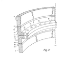
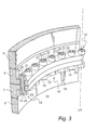
- Figure 2 is a vertical cross-sectional view of a portion of an upper 8 and a lower 9 tower section with corresponding flanges 6, 7.
- Each tower section 8, 9 normally comprises a flange positioned at each end of the tower section.
- a first flange 6 is attached to the upper tower section 8 and a second flange 7 is attached to the lower tower section 9.
- each flange 6, 7 runs along the entire circumference of the associated tower section 8, 9. It is to be understood that the flanges may also be divided into a number of flange sections which together form a circumferential continuous or non-continuous flange.
- each flange 6, 7 is normally mounted as a separate part to the individual tower section by using a suitable joining technique, for example welding.
- the first flange 6 has a substantially L-shaped cross-section with a first leg 10 extending horizontally towards the interior of the tower, thus forming a substantially perpendicular angle with the longitudinal axis LA of the tower sections 8 and 9, and a second leg 11 attached to the upper tower section 8 by means of a welding seam 50 at the lower edge 12 of said upper tower section 8.
- the second flange 7 also has a substantially L-shaped cross-section with a first leg 13 extending horizontally towards the interior of the tower, thus forming a substantially perpendicular angle with the longitudinal axis LA of the tower sections 8, 9, and a second leg 14 attached to the lower tower section 9 by means of a welding seam 50 at the upper edge 15 of said lower tower section 9.
- the inwards extending horizontal first legs 10, 13 of the first and second flanges 6, 7 are in direct contact with each other.
- Each flange 6, 7 is provided along its circumferential extension with a number of through-holes 16.
- the through-holes 16 may be circumferentially equally spaced from one another or arranged in groups.
- the through-holes 16 of the first flange 6 are aligned with the through-holes of the second flange 7.
- the flanges 6, 7 are used as flat support surfaces when the two adjacent, upper 8 and lower 9, tower sections are to be interconnected.
- the flanges 6, 7 are interconnected by means of a plurality of sets 18 of bolts 19 and nuts 20 engaging said through-holes 16.
- the bolts can be provided with washers (not shown).
- each bolt 19 is arranged such that a bolt head 25 thereof, when installed, is orientated downwards.
- upwards orientated bolt heads 25 are also conceivable.
- standardized and readily available bolts are used.
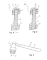
- the bolt 19 can be threaded along the full length of its shaft 26 or, as shown, be threaded only along its free end.
- each nut 20 has an internal thread which engages the threaded section of the bolt shaft 26.
- the nut 20 according to the shown embodiment has circular cross-section, although it is to be understood that other cross-sectional shapes are equally possible. This also applies to the bolt head 25.
- the surface 22 of the nut 20 facing away from the bolt head 25 and flange is provided with a plurality of recesses 21 extending in the longitudinal direction of the shaft 26.
- the recesses 21 are shaped as cylindrical blind bores and arranged parallel to one another and circumferentially uniformly distributed. Still it is to be understood that any pattern and geometry can be used. Also, it is to be understood that the recesses can be arranged as through-holes. Typically, there are 6-12 recesses 21 per nut 20, depending on the size of the nut.
- the bolt head 25 as such can be provided with recesses corresponding to the recesses of the nut.
- the bolt can be a so called stud bolt 19', i.e a shaft 26' provided with threads, either along its full length or along its two free ends.
- stud bolt 19' is used together with two nuts 20', each having the above disclosed recesses 21.
- FIG. 6 shows one embodiment of a tightening device 27.
- the tightening device 27 typically comprises an engagement head 30 having a plurality of circumferentially distributed projections 28.
- the distribution pattern as well as the size and geometry of the projections 28 correspond to those of the recesses 21 of the nut 20.
- a dedicated tightening device 27 may be made available for each nut size.
- the tightening device 27 may, as shown in Figure 6 , include a handle handle 31 adapted to operate in conjunction with the engagement head 30.
- the handle 31 can be a fixed handle, an interchangeable handle or even a ratchet wrench.
- the projections 28 of the tightening device 27 are fully insertable into said recesses 21. This means that the contact between the nut surface 22 provided with recesses 21 and the surface of the tightening device 27 from which the projections 28 extend is ensured. Consequently, the friction between the inner lateral surfaces of the recesses and the outer lateral surfaces of the projections provide additional grip while the nut 20 is being tightened.
- the tightening device 27 can engage the nut 20 and tighten it on the bolt 19 without engaging the lateral surfaces of the nut 20. As a consequence, less space is required in order to tighten individual nuts 20.
- each flange has a T-shaped cross-section with a first leg extending horizontally into the interior of the tower and a second leg extending horizontally to the exterior of the tower, wherein both legs are provided with through-holes to receive sets of bolts and nuts.
- the above disclosed flange joint has been described with regard to two adjacent, upper and lower, tower sections that are to be interconnected.
- the disclosed flange joint is also conceivable with regard to other elements of the wind power plant, such as between a tower section and a part of a tower foundation or between the nacelle and an upper most tower section.
- said bolts are preferably arranged to extend through a yaw system, which yaw system allows the nacelle to turn in view of the tower.
- the flange joint is also applicable while connecting other elements such as transition pieces to the tower sections.
Applications Claiming Priority (2)
| Application Number | Priority Date | Filing Date | Title |
|---|---|---|---|
| DKPA200801671 | 2008-11-27 | ||
| US11868008P | 2008-12-01 | 2008-12-01 |
Publications (2)
| Publication Number | Publication Date |
|---|---|
| EP2192245A1 true EP2192245A1 (fr) | 2010-06-02 |
| EP2192245B1 EP2192245B1 (fr) | 2012-05-30 |
Family
ID=41323397
Family Applications (1)
| Application Number | Title | Priority Date | Filing Date |
|---|---|---|---|
| EP09175409A Active EP2192245B1 (fr) | 2008-11-27 | 2009-11-09 | Tour d'une turbine aeolienne et procédée de assemblage du tour |
Country Status (4)
| Country | Link |
|---|---|
| US (1) | US20100126079A1 (fr) |
| EP (1) | EP2192245B1 (fr) |
| CN (1) | CN101749199A (fr) |
| ES (1) | ES2386519T3 (fr) |
Cited By (11)
| Publication number | Priority date | Publication date | Assignee | Title |
|---|---|---|---|---|
| WO2011147475A1 (fr) * | 2010-05-25 | 2011-12-01 | Siemens Aktiengesellschaft | Structure de chemise pour constructions en mer |
| NL2008493C2 (en) * | 2012-03-15 | 2013-09-18 | Ihc Handling Systems Vof | Flange locking device. |
| EP2664714A1 (fr) * | 2012-05-16 | 2013-11-20 | Christian Schmees | Procédé de fabrication d'un corps de fondement en béton pour la tour d'une éolienne |
| DE102012015489A1 (de) * | 2012-08-04 | 2014-02-06 | E.N.O. Energy Systems Gmbh | Verfahren zum Errichten eines Turmes aus Stahl einer Windenergieanlage und Turm aus Stahl für eine Windenergieanlage |
| NL2010845C2 (en) * | 2013-05-23 | 2014-11-26 | Ihc Hydrohammer B V | An assembly of a tower and a monopile. |
| US20150089782A1 (en) * | 2013-09-27 | 2015-04-02 | Robert F. Wasileski, III | Positioning arrangement having adjustable alignment constraint for low pressure steam turbine inner casing |
| EP2927485A1 (fr) * | 2014-03-31 | 2015-10-07 | Alstom Renovables España, S.L. | Alignement des composants de turbine éolienne |
| EP2674620A3 (fr) * | 2012-06-15 | 2016-10-19 | Siegthalerfabrik GmbH | Pièce de bride pour une tour d'une installation éolienne |
| WO2018213034A3 (fr) * | 2017-05-16 | 2019-01-24 | General Electric Company | Bride de tour pour éolienne |
| WO2021078884A1 (fr) | 2019-10-25 | 2021-04-29 | Mhi Vestas Offshore Wind A/S | Installation de tour d'éolienne et procédé d'assemblage de celle-ci |
| DE112019004572T5 (de) | 2018-09-13 | 2021-07-29 | Frank Bollmann | Modulares system zum bau, zur führung und zur befestigung von elementen rohrförmiger strukturen und entsprechende rohrförmige struktur |
Families Citing this family (26)
| Publication number | Priority date | Publication date | Assignee | Title |
|---|---|---|---|---|
| WO2007059768A1 (fr) * | 2005-11-24 | 2007-05-31 | Vestas Wind Systems A/S | Tour eolienne, moyen de raccordement pour monter une tour eolienne et procedes correspondants |
| CA2668177C (fr) * | 2007-08-31 | 2012-10-23 | Mitsubishi Heavy Industries, Ltd. | Accouplement a bride pour element tubulaire |
| DE102009013186B4 (de) * | 2008-12-19 | 2015-05-28 | Senvion Se | Turm einer Windenergieanlage |
| ES2378199B1 (es) * | 2009-06-24 | 2013-06-05 | Acciona Windpower S.A. | Sistema de unión de una góndola con la torre de hormigón de un aerogenerador. |
| US7997876B2 (en) * | 2010-03-31 | 2011-08-16 | General Electric Company | Wind turbine, tower and method for fabricating the same |
| US20110131898A1 (en) * | 2010-04-29 | 2011-06-09 | Jacob Johannes Nies | Flange connection |
| CN103124823B (zh) * | 2010-07-13 | 2016-05-04 | 安德森塔沃森有限公司 | 使用螺纹接头组装管状建筑结构的方法 |
| US20110138706A1 (en) * | 2010-08-13 | 2011-06-16 | Stefan Voss | Wind turbine anchor element |
| JP5667822B2 (ja) * | 2010-09-21 | 2015-02-12 | 株式会社日立製作所 | 風車タワー内の部品搭載構造 |
| US20110140447A1 (en) * | 2010-11-10 | 2011-06-16 | Ingo Paura | Reinforcement assembly for use with a support tower of a wind turbine |
| DE102011003164A1 (de) * | 2011-01-26 | 2012-07-26 | Aloys Wobben | Verfahren und Vorrichtung zum Errichten eines Turms einer Windenergieanlage |
| US8209913B2 (en) * | 2011-02-01 | 2012-07-03 | Mitsubishi Heavy Industries, Ltd. | Tubular structure and wind turbine generator |
| CH705514A1 (de) * | 2011-09-05 | 2013-03-15 | Alstom Technology Ltd | Gaskanal für eine Gasturbine sowie Gasturbine mit einem solchen Gaskanal. |
| CN102678694B (zh) * | 2012-06-06 | 2013-12-04 | 国电联合动力技术有限公司 | 大型风电机组筒式塔架的无法兰连接方式及其实施方法 |
| ES2471641B1 (es) * | 2012-12-21 | 2015-04-07 | Acciona Windpower, S.A. | Dovela prefabricada de hormigón, torre de aerogenerador que comprende dicha dovela, aerogenerador que comprende dicha torre y procedimiento de montaje de dicho aerogenerador |
| DE102013011479A1 (de) | 2013-02-07 | 2014-08-07 | E.N.O. Energy Systems Gmbh | Flanschverbindung für Bauelemente eines Turmes und Verfahren zum Verbinden von Bauelementen eines Turmes |
| US20140301802A1 (en) * | 2013-04-05 | 2014-10-09 | Eugeniusz Kozak | Zero-Backlash Bushing |
| DE102013110529B4 (de) * | 2013-09-24 | 2020-07-02 | Thyssenkrupp Steel Europe Ag | Strebenanbindung für ein Bauteil einer Stahlkonstruktion |
| FR3029231B1 (fr) * | 2014-12-01 | 2016-12-30 | Lafarge Sa | Section en beton |
| EP3277952B1 (fr) * | 2015-04-02 | 2019-02-27 | ArcelorMittal | Tronçon de mât d'éolienne, mât d'éolienne et procédé d'assemblage |
| US9850674B1 (en) * | 2016-10-13 | 2017-12-26 | General Electric Company | Vertical joint assembly for wind turbine towers |
| NO345662B1 (en) | 2018-11-02 | 2021-06-07 | Tp Products As | A flange element for a flange connection, a flange connection for a tower structure and a tower structure comprising such a flange connection. |
| NL2022032B1 (en) * | 2018-11-20 | 2020-06-03 | Sif Holding N V | TP-free monopile and method for forming the same |
| US20220228565A1 (en) * | 2019-05-21 | 2022-07-21 | Vestas Wind Systems A/S | A method for erecting a wind turbine tower using stud bolts |
| EP3933146A1 (fr) * | 2020-07-01 | 2022-01-05 | Siemens Gamesa Renewable Energy A/S | Système de goujons pour raccorder des brides |
| CN114111465B (zh) * | 2021-11-08 | 2023-11-17 | 湖北航天技术研究院总体设计所 | 一种航空弹体 |
Citations (5)
| Publication number | Priority date | Publication date | Assignee | Title |
|---|---|---|---|---|
| US3843764A (en) * | 1970-05-26 | 1974-10-22 | Caterpillar Tractor Co | Method of making a non-curing gasket for opposed surfaces |
| DE10223429C1 (de) * | 2002-05-25 | 2003-05-28 | Aloys Wobben | Flanschverbindung |
| US20050072067A1 (en) * | 2001-10-09 | 2005-04-07 | Aloys Wobben | Method for establishing a foundation in particular for a tower of a wind energy plant |
| DE102005052419A1 (de) * | 2005-01-20 | 2006-08-24 | Rheinauer Maschinen & Armaturenbau Faulhaber Und Truttenbach Kg | Schraubverbindung |
| JP2008308945A (ja) * | 2007-06-18 | 2008-12-25 | Nisshin Steel Co Ltd | 引張杭併用コンクリート基礎及びその構築方法 |
Family Cites Families (15)
| Publication number | Priority date | Publication date | Assignee | Title |
|---|---|---|---|---|
| US3210098A (en) * | 1961-07-27 | 1965-10-05 | Gray Tool Co | Transition joint |
| US4032244A (en) * | 1976-04-26 | 1977-06-28 | Quayle Jackson C | Pole top extension bracket |
| US4217738A (en) * | 1978-08-02 | 1980-08-19 | Smith Paul R | Windmill tower |
| DE7922528U1 (de) * | 1979-08-07 | 1979-10-31 | Feller Vertriebs-Gesellschaft Mbh Installationsmaterial, 5880 Luedenscheid | Befestigungsanordnung für elektrische Geräte |
| IT1143397B (it) * | 1981-03-24 | 1986-10-22 | Domenico Groppo | Bullone o dado antifurto |
| US4810919A (en) * | 1987-11-16 | 1989-03-07 | Westinghouse Electric Corp. | Low-torque nuts for stator core through-bolts |
| US5083889A (en) * | 1990-10-04 | 1992-01-28 | Steinbock Rolf H | Structure for preventing escape of jack bolts in apparatus to mechanically stress a bolt-type fastener |
| US5333436A (en) * | 1992-09-14 | 1994-08-02 | Pirod, Inc. | Modular antenna pole |
| US5687537A (en) * | 1996-05-24 | 1997-11-18 | Pi Rod Inc. | Modular antenna pole |
| DK200200178A (da) * | 2002-02-06 | 2003-08-07 | Vestas Wind Sys As | Ophængningsmidler til vindturbinetårne |
| DE20208439U1 (de) * | 2002-05-31 | 2003-10-09 | Voith Paper Patent Gmbh | Schraubelement sowie Verbindungsteile zum Drehen des Schraubelementes |
| CN100342104C (zh) * | 2003-04-09 | 2007-10-10 | 通用电气公司 | 使塔架的两相邻管段的外周壁部分形成不间断连接的方法 |
| US20060086214A1 (en) * | 2004-10-26 | 2006-04-27 | Smed Ole F | Security screw |
| US20080041009A1 (en) * | 2006-08-18 | 2008-02-21 | General Electric | Flangeless support structures |
| DE102007018025A1 (de) * | 2007-04-17 | 2008-10-23 | Nordex Energy Gmbh | Windenergieanlagenturm |
-
2009
- 2009-11-09 ES ES09175409T patent/ES2386519T3/es active Active
- 2009-11-09 EP EP09175409A patent/EP2192245B1/fr active Active
- 2009-11-19 CN CN200910222841A patent/CN101749199A/zh active Pending
- 2009-11-25 US US12/626,062 patent/US20100126079A1/en not_active Abandoned
Patent Citations (6)
| Publication number | Priority date | Publication date | Assignee | Title |
|---|---|---|---|---|
| US3843764A (en) * | 1970-05-26 | 1974-10-22 | Caterpillar Tractor Co | Method of making a non-curing gasket for opposed surfaces |
| US20050072067A1 (en) * | 2001-10-09 | 2005-04-07 | Aloys Wobben | Method for establishing a foundation in particular for a tower of a wind energy plant |
| DE10223429C1 (de) * | 2002-05-25 | 2003-05-28 | Aloys Wobben | Flanschverbindung |
| US20060000185A1 (en) | 2002-05-25 | 2006-01-05 | Aloys Wobben | Flange connection |
| DE102005052419A1 (de) * | 2005-01-20 | 2006-08-24 | Rheinauer Maschinen & Armaturenbau Faulhaber Und Truttenbach Kg | Schraubverbindung |
| JP2008308945A (ja) * | 2007-06-18 | 2008-12-25 | Nisshin Steel Co Ltd | 引張杭併用コンクリート基礎及びその構築方法 |
Cited By (17)
| Publication number | Priority date | Publication date | Assignee | Title |
|---|---|---|---|---|
| US9200620B2 (en) | 2010-05-25 | 2015-12-01 | Siemens Aktiengesellschaft | Jacket structure for offshore constructions |
| WO2011147475A1 (fr) * | 2010-05-25 | 2011-12-01 | Siemens Aktiengesellschaft | Structure de chemise pour constructions en mer |
| NL2008493C2 (en) * | 2012-03-15 | 2013-09-18 | Ihc Handling Systems Vof | Flange locking device. |
| WO2013137734A1 (fr) * | 2012-03-15 | 2013-09-19 | Ihc Handling Systems V.O.F. | Dispositif de verrouillage de bride |
| EP2664714A1 (fr) * | 2012-05-16 | 2013-11-20 | Christian Schmees | Procédé de fabrication d'un corps de fondement en béton pour la tour d'une éolienne |
| EP2674620B1 (fr) | 2012-06-15 | 2017-11-15 | Siegthalerfabrik GmbH | Pièce de bride pour une tour d'une installation éolienne |
| EP2674620A3 (fr) * | 2012-06-15 | 2016-10-19 | Siegthalerfabrik GmbH | Pièce de bride pour une tour d'une installation éolienne |
| DE102012015489A1 (de) * | 2012-08-04 | 2014-02-06 | E.N.O. Energy Systems Gmbh | Verfahren zum Errichten eines Turmes aus Stahl einer Windenergieanlage und Turm aus Stahl für eine Windenergieanlage |
| WO2014189367A1 (fr) * | 2013-05-23 | 2014-11-27 | Ihc Holland Ie B.V. | Ensemble de mât et de monopieu |
| NL2010845C2 (en) * | 2013-05-23 | 2014-11-26 | Ihc Hydrohammer B V | An assembly of a tower and a monopile. |
| US20150089782A1 (en) * | 2013-09-27 | 2015-04-02 | Robert F. Wasileski, III | Positioning arrangement having adjustable alignment constraint for low pressure steam turbine inner casing |
| US9309784B2 (en) * | 2013-09-27 | 2016-04-12 | Siemens Energy, Inc. | Positioning arrangement having adjustable alignment constraint for low pressure stream turbine inner casing |
| EP2927485A1 (fr) * | 2014-03-31 | 2015-10-07 | Alstom Renovables España, S.L. | Alignement des composants de turbine éolienne |
| WO2015150316A1 (fr) * | 2014-03-31 | 2015-10-08 | Alstom Renewable Technologies | Alignement de composants d'éolienne |
| WO2018213034A3 (fr) * | 2017-05-16 | 2019-01-24 | General Electric Company | Bride de tour pour éolienne |
| DE112019004572T5 (de) | 2018-09-13 | 2021-07-29 | Frank Bollmann | Modulares system zum bau, zur führung und zur befestigung von elementen rohrförmiger strukturen und entsprechende rohrförmige struktur |
| WO2021078884A1 (fr) | 2019-10-25 | 2021-04-29 | Mhi Vestas Offshore Wind A/S | Installation de tour d'éolienne et procédé d'assemblage de celle-ci |
Also Published As
| Publication number | Publication date |
|---|---|
| EP2192245B1 (fr) | 2012-05-30 |
| US20100126079A1 (en) | 2010-05-27 |
| CN101749199A (zh) | 2010-06-23 |
| ES2386519T3 (es) | 2012-08-22 |
Similar Documents
| Publication | Publication Date | Title |
|---|---|---|
| EP2192245B1 (fr) | Tour d'une turbine aeolienne et procédée de assemblage du tour | |
| CA2802432C (fr) | Mat comprenant une piece adaptatrice et procede de fabrication d'un mat comprenant une piece adaptatrice | |
| US7980827B2 (en) | Method and connecting piece for assembling an arm, preferably a windmill arm, in sections | |
| CN104641059B (zh) | 风力发电设施的模块化塔 | |
| US8915043B2 (en) | Bolt connection for a wind tower lattice structure | |
| EP2494198B1 (fr) | Éolienne | |
| US8025485B2 (en) | Wind turbine blade attachment configuration with flattened bolts | |
| US8191316B2 (en) | Off-shore wind turbine and method of erecting a wind turbine tower | |
| US20110154757A1 (en) | Tower section for a wind turbine tower | |
| CN101317006A (zh) | 风轮机塔架、用于装配风轮机塔架的连接装置及其方法 | |
| CN201326524Y (zh) | 风力发电机组混合式塔筒 | |
| CN109642549B (zh) | 塔区段、塔部段、塔、风能设备以及用于制造塔区段和用于连接塔区段的方法 | |
| US11136780B2 (en) | Annular bracket for externally loading a tower segment, external loading system of a hybrid tower, tower section of a hybrid tower, hybrid tower, wind turbine, and assembly method of an external loading system for a hybrid tower | |
| JP6057533B2 (ja) | ジャケット組立てガイド | |
| US9051917B2 (en) | Wind turbine blade | |
| CN106640543A (zh) | 带有扶撑件的用于风力涡轮机的塔架 | |
| US20190292803A1 (en) | Additively manufactured tower structure and method of fabrication | |
| EP2388411A1 (fr) | Tour d'éolienne | |
| KR20220087534A (ko) | 풍력 터빈 타워 시설 및 풍력 터빈 타워 시설의 조립 방법 | |
| CN113692490A (zh) | 塔部段和用于构造塔的方法 | |
| WO2019120401A1 (fr) | Tour d'éolienne haubanée et procédé de transport de tour d'éolienne | |
| US20220298820A1 (en) | Improvements relating to reinforcement of wind turbine towers |
Legal Events
| Date | Code | Title | Description |
|---|---|---|---|
| PUAI | Public reference made under article 153(3) epc to a published international application that has entered the european phase |
Free format text: ORIGINAL CODE: 0009012 |
|
| AK | Designated contracting states |
Kind code of ref document: A1 Designated state(s): AT BE BG CH CY CZ DE DK EE ES FI FR GB GR HR HU IE IS IT LI LT LU LV MC MK MT NL NO PL PT RO SE SI SK SM TR |
|
| AX | Request for extension of the european patent |
Extension state: AL BA RS |
|
| 17P | Request for examination filed |
Effective date: 20100722 |
|
| 17Q | First examination report despatched |
Effective date: 20100819 |
|
| 17Q | First examination report despatched |
Effective date: 20100819 |
|
| GRAP | Despatch of communication of intention to grant a patent |
Free format text: ORIGINAL CODE: EPIDOSNIGR1 |
|
| RAP1 | Party data changed (applicant data changed or rights of an application transferred) |
Owner name: VESTAS WIND SYSTEMS A/S |
|
| GRAS | Grant fee paid |
Free format text: ORIGINAL CODE: EPIDOSNIGR3 |
|
| GRAA | (expected) grant |
Free format text: ORIGINAL CODE: 0009210 |
|
| AK | Designated contracting states |
Kind code of ref document: B1 Designated state(s): AT BE BG CH CY CZ DE DK EE ES FI FR GB GR HR HU IE IS IT LI LT LU LV MC MK MT NL NO PL PT RO SE SI SK SM TR |
|
| REG | Reference to a national code |
Ref country code: GB Ref legal event code: FG4D |
|
| REG | Reference to a national code |
Ref country code: CH Ref legal event code: EP |
|
| REG | Reference to a national code |
Ref country code: AT Ref legal event code: REF Ref document number: 560150 Country of ref document: AT Kind code of ref document: T Effective date: 20120615 |
|
| REG | Reference to a national code |
Ref country code: IE Ref legal event code: FG4D |
|
| REG | Reference to a national code |
Ref country code: DE Ref legal event code: R096 Ref document number: 602009007302 Country of ref document: DE Effective date: 20120726 |
|
| REG | Reference to a national code |
Ref country code: ES Ref legal event code: FG2A Ref document number: 2386519 Country of ref document: ES Kind code of ref document: T3 Effective date: 20120822 |
|
| REG | Reference to a national code |
Ref country code: NL Ref legal event code: VDEP Effective date: 20120530 |
|
| REG | Reference to a national code |
Ref country code: LT Ref legal event code: MG4D Effective date: 20120530 |
|
| PG25 | Lapsed in a contracting state [announced via postgrant information from national office to epo] |
Ref country code: NO Free format text: LAPSE BECAUSE OF FAILURE TO SUBMIT A TRANSLATION OF THE DESCRIPTION OR TO PAY THE FEE WITHIN THE PRESCRIBED TIME-LIMIT Effective date: 20120830 Ref country code: FI Free format text: LAPSE BECAUSE OF FAILURE TO SUBMIT A TRANSLATION OF THE DESCRIPTION OR TO PAY THE FEE WITHIN THE PRESCRIBED TIME-LIMIT Effective date: 20120530 Ref country code: SE Free format text: LAPSE BECAUSE OF FAILURE TO SUBMIT A TRANSLATION OF THE DESCRIPTION OR TO PAY THE FEE WITHIN THE PRESCRIBED TIME-LIMIT Effective date: 20120530 Ref country code: LT Free format text: LAPSE BECAUSE OF FAILURE TO SUBMIT A TRANSLATION OF THE DESCRIPTION OR TO PAY THE FEE WITHIN THE PRESCRIBED TIME-LIMIT Effective date: 20120530 Ref country code: IS Free format text: LAPSE BECAUSE OF FAILURE TO SUBMIT A TRANSLATION OF THE DESCRIPTION OR TO PAY THE FEE WITHIN THE PRESCRIBED TIME-LIMIT Effective date: 20120930 Ref country code: CY Free format text: LAPSE BECAUSE OF FAILURE TO SUBMIT A TRANSLATION OF THE DESCRIPTION OR TO PAY THE FEE WITHIN THE PRESCRIBED TIME-LIMIT Effective date: 20120530 |
|
| REG | Reference to a national code |
Ref country code: AT Ref legal event code: MK05 Ref document number: 560150 Country of ref document: AT Kind code of ref document: T Effective date: 20120530 |
|
| PG25 | Lapsed in a contracting state [announced via postgrant information from national office to epo] |
Ref country code: GR Free format text: LAPSE BECAUSE OF FAILURE TO SUBMIT A TRANSLATION OF THE DESCRIPTION OR TO PAY THE FEE WITHIN THE PRESCRIBED TIME-LIMIT Effective date: 20120831 Ref country code: HR Free format text: LAPSE BECAUSE OF FAILURE TO SUBMIT A TRANSLATION OF THE DESCRIPTION OR TO PAY THE FEE WITHIN THE PRESCRIBED TIME-LIMIT Effective date: 20120530 Ref country code: LV Free format text: LAPSE BECAUSE OF FAILURE TO SUBMIT A TRANSLATION OF THE DESCRIPTION OR TO PAY THE FEE WITHIN THE PRESCRIBED TIME-LIMIT Effective date: 20120530 Ref country code: SI Free format text: LAPSE BECAUSE OF FAILURE TO SUBMIT A TRANSLATION OF THE DESCRIPTION OR TO PAY THE FEE WITHIN THE PRESCRIBED TIME-LIMIT Effective date: 20120530 |
|
| PG25 | Lapsed in a contracting state [announced via postgrant information from national office to epo] |
Ref country code: BE Free format text: LAPSE BECAUSE OF FAILURE TO SUBMIT A TRANSLATION OF THE DESCRIPTION OR TO PAY THE FEE WITHIN THE PRESCRIBED TIME-LIMIT Effective date: 20120530 |
|
| PG25 | Lapsed in a contracting state [announced via postgrant information from national office to epo] |
Ref country code: NL Free format text: LAPSE BECAUSE OF FAILURE TO SUBMIT A TRANSLATION OF THE DESCRIPTION OR TO PAY THE FEE WITHIN THE PRESCRIBED TIME-LIMIT Effective date: 20120530 Ref country code: DK Free format text: LAPSE BECAUSE OF FAILURE TO SUBMIT A TRANSLATION OF THE DESCRIPTION OR TO PAY THE FEE WITHIN THE PRESCRIBED TIME-LIMIT Effective date: 20120530 Ref country code: AT Free format text: LAPSE BECAUSE OF FAILURE TO SUBMIT A TRANSLATION OF THE DESCRIPTION OR TO PAY THE FEE WITHIN THE PRESCRIBED TIME-LIMIT Effective date: 20120530 Ref country code: RO Free format text: LAPSE BECAUSE OF FAILURE TO SUBMIT A TRANSLATION OF THE DESCRIPTION OR TO PAY THE FEE WITHIN THE PRESCRIBED TIME-LIMIT Effective date: 20120530 Ref country code: CZ Free format text: LAPSE BECAUSE OF FAILURE TO SUBMIT A TRANSLATION OF THE DESCRIPTION OR TO PAY THE FEE WITHIN THE PRESCRIBED TIME-LIMIT Effective date: 20120530 Ref country code: EE Free format text: LAPSE BECAUSE OF FAILURE TO SUBMIT A TRANSLATION OF THE DESCRIPTION OR TO PAY THE FEE WITHIN THE PRESCRIBED TIME-LIMIT Effective date: 20120530 Ref country code: SK Free format text: LAPSE BECAUSE OF FAILURE TO SUBMIT A TRANSLATION OF THE DESCRIPTION OR TO PAY THE FEE WITHIN THE PRESCRIBED TIME-LIMIT Effective date: 20120530 |
|
| PG25 | Lapsed in a contracting state [announced via postgrant information from national office to epo] |
Ref country code: PT Free format text: LAPSE BECAUSE OF FAILURE TO SUBMIT A TRANSLATION OF THE DESCRIPTION OR TO PAY THE FEE WITHIN THE PRESCRIBED TIME-LIMIT Effective date: 20121001 Ref country code: IT Free format text: LAPSE BECAUSE OF FAILURE TO SUBMIT A TRANSLATION OF THE DESCRIPTION OR TO PAY THE FEE WITHIN THE PRESCRIBED TIME-LIMIT Effective date: 20120530 Ref country code: PL Free format text: LAPSE BECAUSE OF FAILURE TO SUBMIT A TRANSLATION OF THE DESCRIPTION OR TO PAY THE FEE WITHIN THE PRESCRIBED TIME-LIMIT Effective date: 20120530 |
|
| PLBE | No opposition filed within time limit |
Free format text: ORIGINAL CODE: 0009261 |
|
| STAA | Information on the status of an ep patent application or granted ep patent |
Free format text: STATUS: NO OPPOSITION FILED WITHIN TIME LIMIT |
|
| 26N | No opposition filed |
Effective date: 20130301 |
|
| REG | Reference to a national code |
Ref country code: DE Ref legal event code: R097 Ref document number: 602009007302 Country of ref document: DE Effective date: 20130301 |
|
| PG25 | Lapsed in a contracting state [announced via postgrant information from national office to epo] |
Ref country code: BG Free format text: LAPSE BECAUSE OF FAILURE TO SUBMIT A TRANSLATION OF THE DESCRIPTION OR TO PAY THE FEE WITHIN THE PRESCRIBED TIME-LIMIT Effective date: 20120830 |
|
| REG | Reference to a national code |
Ref country code: IE Ref legal event code: MM4A |
|
| PG25 | Lapsed in a contracting state [announced via postgrant information from national office to epo] |
Ref country code: IE Free format text: LAPSE BECAUSE OF NON-PAYMENT OF DUE FEES Effective date: 20121109 |
|
| PG25 | Lapsed in a contracting state [announced via postgrant information from national office to epo] |
Ref country code: MT Free format text: LAPSE BECAUSE OF FAILURE TO SUBMIT A TRANSLATION OF THE DESCRIPTION OR TO PAY THE FEE WITHIN THE PRESCRIBED TIME-LIMIT Effective date: 20120530 |
|
| PG25 | Lapsed in a contracting state [announced via postgrant information from national office to epo] |
Ref country code: TR Free format text: LAPSE BECAUSE OF FAILURE TO SUBMIT A TRANSLATION OF THE DESCRIPTION OR TO PAY THE FEE WITHIN THE PRESCRIBED TIME-LIMIT Effective date: 20120530 Ref country code: MC Free format text: LAPSE BECAUSE OF NON-PAYMENT OF DUE FEES Effective date: 20121130 |
|
| PG25 | Lapsed in a contracting state [announced via postgrant information from national office to epo] |
Ref country code: SM Free format text: LAPSE BECAUSE OF FAILURE TO SUBMIT A TRANSLATION OF THE DESCRIPTION OR TO PAY THE FEE WITHIN THE PRESCRIBED TIME-LIMIT Effective date: 20120530 Ref country code: LU Free format text: LAPSE BECAUSE OF NON-PAYMENT OF DUE FEES Effective date: 20121109 |
|
| REG | Reference to a national code |
Ref country code: CH Ref legal event code: PL |
|
| PG25 | Lapsed in a contracting state [announced via postgrant information from national office to epo] |
Ref country code: HU Free format text: LAPSE BECAUSE OF FAILURE TO SUBMIT A TRANSLATION OF THE DESCRIPTION OR TO PAY THE FEE WITHIN THE PRESCRIBED TIME-LIMIT Effective date: 20091109 Ref country code: LI Free format text: LAPSE BECAUSE OF NON-PAYMENT OF DUE FEES Effective date: 20131130 Ref country code: CH Free format text: LAPSE BECAUSE OF NON-PAYMENT OF DUE FEES Effective date: 20131130 |
|
| PG25 | Lapsed in a contracting state [announced via postgrant information from national office to epo] |
Ref country code: MK Free format text: LAPSE BECAUSE OF FAILURE TO SUBMIT A TRANSLATION OF THE DESCRIPTION OR TO PAY THE FEE WITHIN THE PRESCRIBED TIME-LIMIT Effective date: 20120530 |
|
| REG | Reference to a national code |
Ref country code: FR Ref legal event code: PLFP Year of fee payment: 7 |
|
| REG | Reference to a national code |
Ref country code: FR Ref legal event code: CA Effective date: 20160602 |
|
| REG | Reference to a national code |
Ref country code: FR Ref legal event code: PLFP Year of fee payment: 8 |
|
| REG | Reference to a national code |
Ref country code: FR Ref legal event code: PLFP Year of fee payment: 9 |
|
| PGFP | Annual fee paid to national office [announced via postgrant information from national office to epo] |
Ref country code: DE Payment date: 20220127 Year of fee payment: 13 |
|
| PGFP | Annual fee paid to national office [announced via postgrant information from national office to epo] |
Ref country code: GB Payment date: 20221122 Year of fee payment: 14 Ref country code: FR Payment date: 20221122 Year of fee payment: 14 Ref country code: ES Payment date: 20221213 Year of fee payment: 14 |
|
| REG | Reference to a national code |
Ref country code: DE Ref legal event code: R119 Ref document number: 602009007302 Country of ref document: DE |
|
| PG25 | Lapsed in a contracting state [announced via postgrant information from national office to epo] |
Ref country code: DE Free format text: LAPSE BECAUSE OF NON-PAYMENT OF DUE FEES Effective date: 20230601 |