EP2187704A1 - Gargerät und Verfahren zur Abstrahlung von Mikrowellen in einen Innenraum eines Gargeräts - Google Patents
Gargerät und Verfahren zur Abstrahlung von Mikrowellen in einen Innenraum eines Gargeräts Download PDFInfo
- Publication number
- EP2187704A1 EP2187704A1 EP08291071A EP08291071A EP2187704A1 EP 2187704 A1 EP2187704 A1 EP 2187704A1 EP 08291071 A EP08291071 A EP 08291071A EP 08291071 A EP08291071 A EP 08291071A EP 2187704 A1 EP2187704 A1 EP 2187704A1
- Authority
- EP
- European Patent Office
- Prior art keywords
- cooking
- microwaves
- interior
- cooking appliance
- space
- Prior art date
- Legal status (The legal status is an assumption and is not a legal conclusion. Google has not performed a legal analysis and makes no representation as to the accuracy of the status listed.)
- Granted
Links
Images

Classifications
-
- H—ELECTRICITY
- H05—ELECTRIC TECHNIQUES NOT OTHERWISE PROVIDED FOR
- H05B—ELECTRIC HEATING; ELECTRIC LIGHT SOURCES NOT OTHERWISE PROVIDED FOR; CIRCUIT ARRANGEMENTS FOR ELECTRIC LIGHT SOURCES, IN GENERAL
- H05B6/00—Heating by electric, magnetic or electromagnetic fields
- H05B6/64—Heating using microwaves
- H05B6/72—Radiators or antennas
-
- H—ELECTRICITY
- H05—ELECTRIC TECHNIQUES NOT OTHERWISE PROVIDED FOR
- H05B—ELECTRIC HEATING; ELECTRIC LIGHT SOURCES NOT OTHERWISE PROVIDED FOR; CIRCUIT ARRANGEMENTS FOR ELECTRIC LIGHT SOURCES, IN GENERAL
- H05B6/00—Heating by electric, magnetic or electromagnetic fields
- H05B6/64—Heating using microwaves
- H05B6/642—Cooling of the microwave components and related air circulation systems
-
- H—ELECTRICITY
- H05—ELECTRIC TECHNIQUES NOT OTHERWISE PROVIDED FOR
- H05B—ELECTRIC HEATING; ELECTRIC LIGHT SOURCES NOT OTHERWISE PROVIDED FOR; CIRCUIT ARRANGEMENTS FOR ELECTRIC LIGHT SOURCES, IN GENERAL
- H05B6/00—Heating by electric, magnetic or electromagnetic fields
- H05B6/64—Heating using microwaves
- H05B6/70—Feed lines
Definitions
- the invention relates to a cooking appliance, comprising an interior, which has at least one cooking chamber, and at least one microwave source comprising an oscillator device for generating microwaves and at least one outcoupling element for coupling the microwaves generated in the oscillator device from the microwave source. Furthermore, the invention relates to a method for emitting microwaves in an interior of a cooking appliance.
- the US 5,237,141 discloses a high frequency heating apparatus comprising means for generating microwave energy for heating food in a chamber.
- the microwave generating means comprise a microwave radiator located on one of the side inner walls of the chamber without further details being described.
- the EP 0 429 822 A1 discloses a generic cooking appliance, which has a metallic enclosure for limiting a cooking chamber and a microwave source with two magnetrons.
- the cooking chamber is subdivided into a further interior space by a dividing wall which extends over the entire height and a part of the width of the cooking space.
- the microwave heating is achieved in that symmetrically two magnetrons are arranged on the outside of the cooking chamber, wherein the magnetrons are connected to the cooking chamber by means of two identical, arranged on the side and symmetrical funnel-shaped structures, wherein the structures cover not only the respective magnetron, but
- a disadvantage of the known cooking appliance is the fact that the funnel-shaped structures and the mode mixing device should be adapted to the respective magnetron so that no losses occur when guiding the microwaves into the cooking space. Reflections that could lead to overheating of the magnetron must also be avoided in a complex manner.
- the invention is therefore based on the object to further develop the generic cooking appliance and method such that the disadvantages of the prior art are at least partially overcome.
- the object relating to the cooking appliance is achieved in that the decoupling element leads the microwaves to be coupled out to a gate in a wall or a wall section of the interior and radiates the microwaves out of the gate directly into the interior.
- the decoupling element comprises at least one projecting from the wall antenna part.
- the gate comprises a hood made of dielectric material which separates the coupling-out element from the atmosphere in the interior, wherein in particular the hood is fastened to the wall or the wall section via at least one flange connection and / or under use a sealing element.
- the hood can be made of glass, in particular tempered borosilicate or quartz glass, and / or ceramic, in particular Al 2 O 3 or ZrO 2 include.
- the interior is at least partially divided into the cooking chamber and a pressure chamber via at least one flow guide, a fan wheel and the Auskoppelement are arranged in the pressure chamber, wherein the coupling element leads the microwaves auskoppelnden to the gate in the wall section, in particular a Inclination to the adjacent thereto walls, in particular side walls of the interior, is movable, and / or is aligned to a point of the interior, in particular the center of the cooking chamber, the Strömungsleiglied with at least one, in particular central, opening for sucking atmosphere from the cooking chamber is provided in the pressure chamber, and the flow guide between the pressure chamber and the cooking chamber, in particular at its edge region and in its center, at least one air-permeable compound leaves free.
- Each microwave source can be provided on an outer side of the interior, in particular on the outside of a side wall of a pressure chamber arranged next to the cooking chamber and / or in an installation space which additionally contains drive means for a fan wheel located in the pressure space, wherein in particular at least one of the doors in FIG a wall portion, which is at an angle to one of a drive shaft of the fan wheel protrudes sidewall, is provided, wherein preferably a first gate above the fan and a second gate is arranged below the fan.
- the cooking appliance can have a plurality of microwave sources, which are arranged at different heights in the cooking appliance and / or each have a nominal power of 2000 watts HF or less, and / or have a product carrier system defining a plurality of treatment levels in the cooking space, wherein in particular the number of microwave oven sources Microwave sources on the dimension of the cooking chamber and / or the number of treatment levels depends.
- the cooking appliance can furthermore be provided with at least one further device for the treatment of food to be cooked in the cooking chamber, in particular at least one device from the group comprising: an electric heating device, a gas-operated heating device, a heat exchange device, a cooling device, a moisture supply device, a moisture removal device, a ventilation device and a venting device.
- at least one device from the group comprising: an electric heating device, a gas-operated heating device, a heat exchange device, a cooling device, a moisture supply device, a moisture removal device, a ventilation device and a venting device.
- the walls of the interior, a flow guide, over which the interior is at least partially divided into the cooking chamber and a pressure chamber, and / or provided in the cooking space Gargutla worn at least partially reflected or reflected microwaves.
- An embodiment may be provided with at least one sensing device, a display device, an operating device and a control or regulating device, wherein the sensing device in particular with each microwave source, another treatment device, the display device, the operating device and / or the control or regulating device is in operative connection
- the object concerning the method for emitting microwaves in an interior of a cooking device is achieved according to the invention by emitting the microwaves via a decoupling element along a direct path into the interior.
- a plurality of treatment levels in the cooking chamber is determined via a food support device, and a number of microwave sources is provided which is dimensioned according to the dimensioning of the cooking chamber and / or the number of treatment levels.
- direct radiation or a direct path of radiated microwaves is understood to mean that microwave radiation is allowed to pass from a microwave source into the cooking chamber of a cooking appliance without reflections or even waveform changes.
- a gate forms the entrance to the interior having the cooking chamber and comprises at least one opening in the lining of the interior.
- the invention is based on the surprising finding that in that a coupling-out element microwaves directly from a structure in the microwaves from a microwave source amplified - as by interaction between an electron beam and a microwave signal to be amplified - decoupled, so that they pass through a gate into the interior of a cooking appliance, which includes at least the cooking chamber, the usual necessary for the protection of the microwave source parts, such as waveguides and circulators , omitted. Another effect of this arrangement is that it is relatively compact.
- the coupling-out element comprises at least one antenna part projecting from the wall
- the sealing towards the interior is simpler than would be the case with a waveguide.
- the radiation characteristic is then favorable, because the microwaves are radiated in the direction of all inner walls or inner wall sections adjacent to the inner wall.
- the door comprises a hood of dielectric material separating the decoupling element from the atmosphere in the interior
- the hood transmits the microwaves into the interior, but thermally isolates the microwave source from the interior.
- this insulation is advantageous because in such cooking appliances a high temperature prevails.
- Another effect is that also an additional insulation against liquid is made.
- the hood is attached to the wall, at the same time the space in which the microwave source is located, sealed against the interior of the cooking appliance. Otherwise, an additional seal would be required in the area of the microwave source, if in fact the space in which the microwave source is located should be sealed off from the interior.
- a flange connection makes it possible to produce the inner wall from a metallic material.
- a flange connection also compensates for the effects of different thermal expansion coefficients of the hood and the wall. If the attachment to the wall comprises at least one sealing element, gases can not easily escape from the cooking chamber.
- the hood is made of glass, in particular tempered borosilicate or quartz glass, it has a low dielectric constant and a relatively high thermal resistance.
- the hood can also be made of high-purity oxides such as Al 2 O 3 and ZrO 2 .
- the Strömungsleitglied with at least one, in particular central, opening for sucking atmosphere from the cooking chamber is provided in the pressure chamber and the flow guide between the pressure chamber and the cooking chamber, in particular at its edge region, at least one, in particular slit-shaped, air-permeable compound leaves free, form the pressure chamber and the cooking chamber two coupled resonators for the microwaves. It is therefore irrelevant in which of the two rooms the microwaves are first radiated.
- the circulation of the atmosphere in the interior via the fan wheel ensures a mixture of modes and equalization of the microwave energy.
- a steam injection device may be provided which injects steam into the flow, or an electric heater or gas-powered heater may be provided for heating the pumped medium.
- an electric heater or gas-powered heater may be provided for heating the pumped medium.
- each microwave source is provided on an outer side of the inner space, in particular on the outer side of a side wall of a pressure space arranged next to the cooking space, the fan wheel will usually reflect microwaves, so that better mode mixing is achieved without additional measures.
- an additional function is provided in an efficient manner, since the fan wheel already exists in combination cooking appliances anyway.
- the arrangement of the microwave source on an outside of a side wall of the interior is advantageous because the fact that no microwave source is present on the ceiling of the interior, the size is minimized. This in turn is desirable so that two cooking devices can be stacked without affecting operability.
- an arrangement on a side wall has the advantage that the requirements in terms of the seal is not that high.
- the arrangement on a wall portion which is at an angle to a projected by a drive shaft of the fan side wall, has the effect that the microwaves are radiated adjacent to the fan. So you are not shielded by the fan. However, it is still a radiation in the direction of the fan present, which is for the turbulence, so the homogenization of the microwave distribution, an advantage.
- microwave sources are arranged at different heights in the cooking appliance and have a respective rated power of 2000 watts HF or less, the power required in consideration of the cooking chamber size can be achieved via commercially available microwave sources.
- the cooking appliance comprises a further device for the treatment (treatment device) of food in the cooking chamber
- the food can be treated in the same cooking appliance in several ways. This increases the efficiency because the food does not have to be constantly removed from the cooking appliance. It also increases the quality, as a precise cooking is possible.
- One effect of a sensing device that is operatively associated with each microwave source, the further treatment device, the display device, the operating device and / or the control or regulating device is that food can be subjected to a complex combination treatment without intervention by a user.
- a plurality of treatment levels in the cooking space is determined via a food support device and a number of microwave sources is provided according to the dimensioning of the cooking space and / or the number of treatment levels
- commercially available microwave sources for example magnetrons, can be used.
- the required overall performance is achieved by providing a sufficient number of microwave sources.
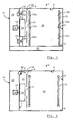
- An example in the Figures 1 and 2 illustrated cooking appliance 1 comprises an interior defined by a rear wall 2, a ceiling 3, a bottom surface 4, a first side wall 5, a front wall 6, a second side wall 7 and a side wall portion 8, the rear wall 2 and the front wall 6 also referred to as side walls can be.
- the interior is at least partially divided by a flow baffle 9 in a cooking chamber 10 and a pressure chamber 11.
- a flow baffle 9 in a cooking chamber 10 and a pressure chamber 11.
- the front wall 6 is a door not shown for loading the cooking chamber 10 with food (not shown) and for removing the same.
- a frame 12 with a plurality of rails 13a-f for insertion of food supports (not shown), on which the food is placed, provided.
- a radial fan 14 which is driven by a motor 16 via a shaft 15.
- the radial fan 14 sucks atmosphere (steam, vapor, air etc.) from the cooking chamber 10 through an opening located in the center of the Strömungsleitblechs 9 17 and blows it off radially.
- atmosphere steam, vapor, air etc.
- the atmosphere is due to this pressure difference through slots 18 between the edge of Strömungsleitblechs 9 and at least one of the rear wall 2, front wall 6, ceiling 3 and bottom surface 4 again led into the cooking chamber 10 ,
- slots 18 it is also possible to provide openings in the flow guide plate 9 in the edge area of the flow guide plate 9.
- the illustrated cooking appliance 1 comprises a microwave heating and another, not shown, means for the treatment of food in the cooking chamber 10, such as a ventilation device, an electric heater, a gas-powered heater, a heat exchange device, a cooling device, a moisture supply device and / or a mecanicsabloom surprise.
- a moisture baffle is preferably located in a floor area 19.
- a moisture supply device may include a steam injector that injects steam into the flow.
- each treatment device At least the regulation or control and the electrical connections of each treatment device are located, as well as the motor 16, in an installation space 20 adjacent to the pressure space 11.
- the installation space 20 is directly via a door (not shown) in an outer side wall 21 accessible from outside the cooking appliance 1 to facilitate maintenance and installation.
- Microwaves are generated in magnetrons 22, 23 of the microwave heating.
- the microwaves generated in the magnetrons 22, 23 are guided to a respective gate 24, 25 in order to be radiated on a direct path into the pressure chamber 11.
- the pressure chamber 11 and the cooking chamber 10 form coupled, substantially cuboid resonators for the radiated microwaves. For this reason, finds a uniform microwave energy distribution in the cooking chamber 10 instead.
- the coupling takes place essentially via the slots 18, which are also provided for circulating the cooking chamber atmosphere.
- openings (not shown) for microwave-permeable openings may be provided in the flow guide plate 9. In order to maintain the pressure difference between the pressure chamber 11 and the cooking chamber 10, these openings are not permeable to air, but filled with dielectric material, for example, quartz glass, borosilicate glass or ceramic.
- the radial fan 14 is at least partially made of a material that reflects microwaves.
- the gates 24,25 are located in the side wall portion 8, which adjacent to the second side wall 7 through which the drive shaft 15 of the radial fan 14 projects, is arranged.
- the radial fan 14 extends in the radial direction at most to the transition from the side wall 7 to the side wall portion 8, so that the gates 24,25 are not shielded by the fan 14.
- rod or slot antennas are provided for the radiation in the pressure chamber 11 rod or slot antennas are provided.
- the radiation characteristic is such that at least one radiation takes place parallel to the side wall part 8.
- the radiated so microwaves therefore reach the radial fan 14 and are swirled by him.
- the side wall portion 8 is at an angle to the side wall 7. Due to this arrangement, the microwaves are already partly reflected into the cooking chamber 10 via the rear wall 2.
- a further homogenization of the microwave energy distribution is achieved in that the gates 24,25 are provided at different heights in the interior of the cooking appliance 1.
- the cooking appliance 1 is designed for large kitchen use, commercially available magnetrons 22, 23, which are designed for use in household microwave appliances, are used for cost reasons. These usually have a nominal power of about 2000 watts of HF.
- the number of magnetrons 22,23 depends on the number of rails 13a-f in the frame 12, that is on the number and dimensions of the accommodatable food supports.
- the first magnetron 22 includes a housing 26 from which an antenna stub 27 protrudes.
- the antenna stub 27 also includes a protective cap 28.
- the magnetron 22 includes a cathode 29 which is heated during operation.
- the cathode 29 is surrounded by an anode 30 with projecting, circumferentially arranged wings 31.
- the magnetron also contains a magnet stack 32.
- the electrons emitted by the cathode 29 are guided around the cathode 29 under the influence of the electric and magnetic fields. The reaction of the fields on the incident on the anode 30 electrons creates an oscillation.
- An inner conductor 33 of the antenna couples the generated microwaves out of the oscillator device and radiates them into the pressure chamber 11.
- the microwaves generated in the magnetron 22 are thus emitted directly into the pressure chamber 11 without the interposition of a waveguide.
- some magnetrons instead of the inner conductor 33 may comprise a waveguide for coupling out the microwaves.
- a cooking appliance 1 for the commercial kitchen use differs from a household microwave.
- the moisture in the cooking chamber 10 and in the pressure chamber 11 can be high and the temperature there can reach values of approximately 400 ° C.
- the magnetrons 22,23 should be protected from this atmosphere.
- a cover in the form of a hood 34 is used for such a protection.
- the hood 34 is made of a dielectric material which is permeable to microwaves. The material also has a low thermal conductivity.
- a hood 34 made of ceramic can be used. Due to the low dielectric constant, glass, for example quartz or borosilicate glass (Pyrex), is also suitable as a manufacturing material.
- the hood 34 surrounds the protruding through the side wall portion 8 antenna stub 27 of the magnetron. To increase the thermal insulation is a gap 35 between the inside of the hood 34 and the antenna stub 37. The gap 35 is in particular filled with air.
- the hood 34 is fastened in the illustrated embodiment via a flange 36 to the side wall part 8.
- the hood 34 fulfills the dual function of the gas-tight sealing of the installation space 20 with respect to the interior atmosphere as well as the thermal insulation of the magnetron antenna stub 27.
- the flange also comprises two flat gaskets 37,38, a stainless steel rotary member 39 and screws 40,41 for fixing the stainless steel rotary member 39 at the cooking chamber side of the side wall part. 8
- the direct magnetron coupling has the advantage that the usual in professional Mikrowellengaréen Modenmischerboxen and paddle wheels outside the Garausninnenraums omitted. This also applies to the necessary for the protection of the magnetron from mismatch waveguides, circulators and directional couplers, which are commonly used. Thus, both costs and space in the installation room 20 are saved.
Landscapes
- Physics & Mathematics (AREA)
- Electromagnetism (AREA)
- Constitution Of High-Frequency Heating (AREA)
- Electric Ovens (AREA)
Abstract
Description
- Die Erfindung betrifft ein Gargerät, umfassend einen Innenraum, der zumindest einen Garraum aufweist, und zumindest eine Mikrowellenquelle, die eine Oszillatorvorrichtung zum Generieren von Mikrowellen und zumindest ein Auskoppelelement zum Auskoppeln der in der Oszillatorvorrichtung erzeugten Mikrowellen aus der Mikrowellenquelle umfasst. Ferner betrifft die Erfindung ein Verfahren zur Abstrahlung von Mikrowellen in einen Innenraum eines Gargeräts.
- Die
US 5,237,141 offenbart eine Hochfrequenzerwärmungsvorrichtung, die Mittel zum Generieren von Mikrowellenenergie zur Erwärmung von Gargut in einer Kammer umfasst. Die Mikrowellengeneriermittel umfassen einen Mikrowellenstrahler, der sich an einer der Seiten - innenwände der Kammer befindet, ohne dass weitere Details hierzu beschrieben sind. - Die
EP 0 429 822 A1 offenbart ein gattungsgemäßes Gargerät, das eine metallische Umhüllung zur Begrenzung eines Garraums und eine Mikrowellenquelle mit zwei Magnetrons aufweist. Der Garraum ist in einen weiteren Innenraum durch eine Trennwand unterteilt, welche sich über die ganze Höhe und einen Teil der Breite des Garraums erstreckt. Die Mikrowellenheizung wird dadurch erreicht, dass an der Außenseite des Garraums symmetrisch zwei Magnetrons angeordnet sind, wobei die Magnetrons mit dem Garraum mittels zwei gleicher, an der Seite angeordneter und symmetrischer trichterförmiger Strukturen verbunden sind, wobei die Strukturen nicht nur die jeweiligen Magnetrons abdecken, sondern zudem die Aufgaben erfüllen, einem Entweichen von Strahlung nach Außen vorzubeugen, Strahlung in Richtung des Garraums zu führen und eine spezielle Modenfortpflanzungsmischvorrrichtung aufzunehmen. - Ein Nachteil des bekannten Gargeräts ist darin zu sehen, dass die trichterförmigen Strukturen und die Modenmischvorrichtung dem jeweiligen Magnetron angepasst sein sollen, damit bei der Führung der Mikrowellen in den Garraum keine Verluste auftreten. Reflexionen, die zu einer Überhitzung des Magnetrons führen könnten, müssen auch auf aufwändige Weise vermieden werden.
- Der Erfindung liegt daher die Aufgabe zu Grunde, das gattungsgemäße Gargerät und Verfahren derart weiterzuentwickeln, dass die Nachteile des Stands der Technik zumindest teilweise überwunden werden. Insbesondere soll es ermöglicht werden, auf relativ einfache Weise mit hoher Effizienz Mikrowellen in den Innenraum des Gargeräts einzuspeisen.
- Erfindungsgemäß wird die das Gargerät betreffende Aufgabe dadurch gelöst, dass das Auskoppelelement die auszukoppelnden Mikrowellen zu einer Pforte in einer Wand oder einem Wandabschnitt des Innenraums führt und die Mikrowellen aus der Pforte direkt in den Innenraum abstrahlt.
- Dabei kann vorgesehen sein, dass das Auskoppelelement zumindest einen aus der Wand hervorstehenden Antennenteil umfasst.
- Es kann ferner vorgesehen sein, dass die Pforte eine Haube aus dielektrischem Material, welche das Auskoppelelement von der Atmosphäre im Innenraum trennt, umfasst, wobei insbesondere die Haube an der Wand oder dem Wandabschnitt befestigt ist, über zumindest eine Flanschverbindung und/oder unter Einsatz zumindest eines Dichtelements.
- In einer Variante dieser Ausführungsform kann die Haube aus Glas, insbesondere temperiertem Borsilikat- oder Quarz-Glas, hergestellt sein und/oder Keramik, insbesondere Al2O3 oder ZrO2, umfassen.
- Ferner kann vorgesehen sein, dass der Innenraum über zumindest ein Strömungsleitglied zumindest teilweise in den Garraum und einen Druckraum aufgeteilt ist, im Druckraum ein Lüfterrad und das Auskoppelement angeordnet sind, wobei das Auskoppelelement die auszukoppelnden Mikrowellen zu der Pforte in dem Wandabschnitt führt, der insbesondere eine Neigung zu den dazu benachbarten Wänden, insbesondere Seitenwänden des Innenraums aufweist, bewegbar ist, und/oder zu einem Punkt des Innenraums, insbesondere dem Zentrum des Garraums ausgerichtet ist, das Strömungsleiglied mit zumindest einer, insbesondere mittigen, Öffnung zum Ansaugen von Atmosphäre aus dem Garraum in den Druckraum versehen ist, und das Strömungsleitglied zwischen dem Druckraum und dem Garraum, insbesondere an seinem Randbereich sowie in seinem Zentrum, zumindest eine luftdurchlässige Verbindung freilässt.
- Jede Mikrowellenquelle kann an einer Außenseite des Innenraums, insbesondere an der Außenseite einer Seitenwand eines neben dem Garraum angeordneten Druckraums und/oder in einem Installationsraum, der zusätzlich Antriebsmittel für ein sich im Druckraum befindendes Lüfterrad enthält, vorgesehen sein, wobei insbesondere zumindest eine der Pforten in einem Wandabschnitt, der unter einem Winkel zu einer von einer ein Antriebswelle des Lüfterrads durchragten Seitenwand steht, vorgesehen ist, wobei vorzugsweise eine erste Pforte oberhalb des Lüfterrads und eine zweite Pforte unterhalb des Lüfterrads angeordnet ist.
- Das Gargerät kann eine Vielzahl von Mikrowellenquellen, die auf unterschiedlichen Höhen im Gargerät angeordnet sind und/oder jeweils eine Nennleistung von 2000 Watt HF oder weniger aufweisen, und/oder eine eine Vielzahl von Behandlungsebenen in dem Garraum festlegende Gargutträgereinrichtung aufweisen, wobei insbesondere die Anzahl der Mikrowellenquellen von der Bemaßung des Garraums und/oder der Anzahl der Behandlungsebenen abhängt.
- Das Gargerät kann ferner versehen sein mit zumindest einer weiteren Einrichtung zur Behandlung von Gargut im Garraum, insbesondere zumindest einer Einrichtung aus der Gruppe umfassend: eine elektrische Heizeinrichtung, eine gasbetriebene Heizeinrichtung, ein Wärmetauscheinrichtung, eine Kühleinrichtung, eine Feuchtigikeitszuführeinrichtung, eine Feuchtigkeitsabführeinrichtung, eine Belüftungseinrichtung und eine Entlüftungseinrichtung.
- In einer Ausführungsform kann vorgesehen sein, dass die Wände des Innenraums, ein Strömungsleitglied, über das der Innenraum zumindest teilweise in den Garraum und einen Druckraum aufgeteilt ist, und/oder eine im Garraum vorgesehene Gargutträgereinrichtung zumindest teilweise Mikrowellen reflektiert bzw. reflektieren.
- Eine Ausführungsform kann versehen sein mit zumindest einer Sensiereinrichtung, einer Anzeigeeinrichtung, einer Bedieneinrichtung und einer Steuer- oder Regeleinrichtung, wobei die Sensiereinrichtung insbesondere mit jeder Mikrowellenquelle, einer weiteren Behandlungseinrichtung, der Anzeigeeinrichtung, der Bedieneinrichtung und/oder der Steuer- oder Regeleinrichtung in Wirkverbindung steht
- Die das Verfahren zur Abstrahlung von Mikrowellen in einen Innenraum eines Gargeräts betreffende Aufgabe wird erfindungsgemäß gelöst durch ein Abstrahlen der Mikrowellen über ein Auskoppelelement entlang eines direkten Wegs in den Innenraum.
- Es kann dabei vorgesehen sein, dass über eine Gargutträgereinrichtung eine Vielzahl von Behandlungsebenen in dem Garraum festgelegt wird, und eine sich nach der Bemaßung des Garraums und/oder der Anzahl der Behandlungsebenen richtende Anzahl an Mikrowellenquellen bereitgestellt wird.
- Unter einer direkter Abstrahlung oder einem direkten Weg abgestrahlter Mikrowellen ist im Sinne dieser Anmeldung zu verstehen, dass es einer Mirkowellenstrahlung ermöglicht wird, ohne Reflexionen oder gar Wellenformänderungen von einer Mikrowellenquelle in den Garraum eines Gargeräts zu gelangen. Eine Pforte bildet dabei den Eingang zu dem den Garraum aufweisenden Innenraum und umfasst zumindest eine Öffnung in der Bewandung des Innenraums.
- Der Erfindung liegt die überraschende Erkenntnis zugrunde, dass dadurch, dass ein Auskoppelelement Mikrowellen direkt aus einer Struktur, in der Mikrowellen aus einer Mikrowellenquelle verstärkt werden - etwa durch Interaktion zwischen einem Elektronenbündel und einem zu verstärkenden Mikrowellensignal - auskoppelt, so dass sie über eine Pforte in den Innenraum eines Gargeräts, der zumindest den Garraum umfasst, gelangen, die üblichen zum Schutz der Mikrowellenquelle nötigen Teile, wie Wellenleiter und Zirkulatoren, entfallen. Ein weiterer Effekt dieser Anordnung besteht darin, dass sie relativ kompakt ist.
- Wenn das Auskoppelelement zumindest einen aus der Wand hervorstehenden Antennenteil umfasst, ist die Abdichtung zum Innenraum hin einfacher vorzunehmen, als es bei einem Wellenleiter der Fall wäre. Zudem ist dann die Strahlungscharakteristik günstig, weil die Mikrowellen in Richtung aller der Innenwand benachbarten Innenwände oder Innenwandabschnitte abgestrahlt werden. Bei Verwendung einer λ/4-Antenne wird möglichst viel Energie in den Innenraum eingespeist.
- Wenn die Pforte eine Haube aus dielektrischem Material, welche das Auskoppelelement von der Atmosphäre im Innenraum trennt, umfasst, wird erreicht, dass die Haube die Mikrowellen in den Innenraum durchlässt, jedoch die Mikrowellenquelle thermisch von dem Innenraum isoliert. Insbesondere bei Gargeräten für den Großkücheneinsatz ist diese Isolierung vorteilhaft, weil in solchen Gargeräten eine hohe Temperatur vorherrscht. Ein weiterer Effekt ist, dass auch eine zusätzliche Isolierung gegen Flüssigkeit vorgenommen wird. Wenn die Haube an der Wand befestigt ist, wird zugleich der Raum, in dem sich die Mikrowellenquelle befindet, gegenüber dem Innenraum des Gargeräts abgedichtet. Anderenfalls wäre im Bereich der Mikrowellenquelle noch eine zusätzliche Dichtung erforderlich, falls nämlich der Raum, in dem sich die Mikrowellenquelle befindet, gegenüber dem Innenraum abgedichtet sein sollte, Eine Flanschverbindung ermöglicht es, die Innenwand aus einem metallischen Material herzustellen. Eine Flanschverbindung gleicht auch die Effekte unterschiedlicher Wärmedehnungskoeffizienten der Haube und der Wand aus. Wenn die Befestigung an der Wand zumindest ein Dichtelement umfasst, können Gase nicht leicht aus dem Garraum entweichen.
- Ist die Haube aus Glas, insbesondere temperiertem Borsilikat- oder Quarz-Glas, hergestellt, weist sie eine niedrige dielektrische Konstante und einen relativ hohen Wärmewiderstand auf.
- Alternativ kann die Haube auch aus hochreinen Oxiden wie z.B. Al2O3 und ZrO2 gefertigt werden.
- In dem Fall, in dem der Innenraum über zumindest ein Strömungsleitglied zumindest teilweise in den Garraum und einen Druckraum aufgeteilt ist, im Druckraum ein Lüfterrad und das Auskoppelement angeordnet sind, das Strömungsleitglied mit zumindest einer, insbesondere mittigen, Öffnung zum Ansaugen von Atmosphäre aus dem Garraum in den Druckraum versehen ist und das Strömungsleitglied zwischen dem Druckraum und dem Garraum, insbesondere an seinem Randbereich, zumindest eine, insbesondere schlitzförmige, luftdurchlässige Verbindung freilässt, bilden der Druckraum und der Garraum zwei gekoppelte Resonatoren für die Mikrowellen. Es ist deshalb unerheblich, in welchen der zwei Räume die Mikrowellen zuerst abgestrahlt werden. Zudem sorgt die Umwälzung der Atmosphäre in dem Innenraum über das Lüfterrad für eine Modenmischung und Vergleichmäßigung der Mikrowellenenergie. Zum Beispiel kann zur weiteren Beeinflussung des Garraumklimas eine Dampfeinspritzvorrichtung vorgesehen sein, die Dampf in die Strömung einspritzt, oder es kann eine elektrische Heizung oder gasbetriebene Heizung zum Aufwärmen des geförderten Mediums vorgesehen sein. Insbesondere bei Gargeräten für den Großkücheneinsatz ist die Vergleichmäßigung des Garraumklimas, die durch die Umwälzung der Garraumatmosphäre zustande kommt, von Vorteil.
- Wenn jede Mikrowellenquelle an einer Außenseite des Innenraums, insbesondere an der Außenseite einer Seitenwand eines neben dem Garraum angeordneten Druckraum, vorgesehen ist, wird üblicherweise das Lüfterrad Mikrowellen reflektieren, so dass eine bessere Modenmischung ohne zusätzliche Maßnahmen zustande kommt. Es wird also auf effiziente Weise eine zusätzliche Funktion bereitgestellt, da das Lüfterrad in Kombinationsgargeräten ohnehin schon vorhanden ist. Die Anordnung der Mikrowellenquelle an einer Außenseite einer Seitenwand des Innenraums ist vorteilhaft, weil dadurch, dass an der Decke des Innenraums keine Mikrowellenquelle vorhanden ist, die Baugröße minimiert wird. Dies wiederum ist erwünscht, damit zwei Gargeräte gestapelt werden können, ohne die Bedienbarkeit zu beeinträchtigen. Im Vergleich zu einer Anordnung der Mikrowellenquellen im Bodenbereich des Garraums hat eine Anordnung an einer Seitenwand den Vorteil, dass die Anforderungen hinsichtlich der Dichtung nicht so hoch sind. Insbesondere in Gargeräten für den Großkücheneinsatz befindet sich nämlich im Bodenbereich ziemlich viel Flüssigkeit oder sogar eine Ablaufeinrichtung. Eine Anordnung an einer Seitenwand eines neben dem Garraum angeordneten Druckraums hat den Vorteil, dass auch hier die Anforderungen an die Dichtung nicht so hoch sind, weil eine gewisse Abtrennung vom Garraum schon vorhanden ist. Dadurch, dass der Druckraum und der Garraum gekoppelte Resonatorräume bilden, ist eine Anordnung an einer Seitenwand des Druckraums nicht nachteilig für die Gleichmäßigkeit der Mikrowellenverteilung im Garraum. Bei einer Anordnung in einem gemeinsamen Installationsraum können elektrische Anschlüsse geteilt werden. Zudem gibt es in diesem Fall nur einen Raum, der gasdicht abzutrennen und für Reparatur sowie Wartung gegebenenfalls zugänglich zu machen ist. Die Anordnung an einem Wandabschnitt, der unter einem Winkel zu einer von einer Antriebswelle des Lüfterrads durchragten Seitenwand steht, hat den Effekt, dass die Mikrowellen neben dem Lüfterrad abgestrahlt werden. Sie werden also nicht von dem Lüfterrad abgeschirmt. Es ist jedoch trotzdem eine Abstrahlung in Richtung des Lüfterrads vorhanden, was für die Verwirbelung, also die Vergleichmäßigung der Mikrowellenverteilung, von Vorteil ist.
- Wenn eine Vielzahl von Mikrowellenquellen auf unterschiedlichen Höhen im Gargerät angeordnet sind und eine jeweilige Nennleistung von 2000 Watt HF oder weniger aufweisen, kann die in Anbetracht der Garraumgröße erforderliche Leistung über handelsübliche Mikrowellenquellen erreicht werden.
- Falls das Gargerät eine weitere Einrichtung zur Behandlung (Behandlungseinrichtung) von Gargut im Garraum umfasst, kann das Gargut in ein und demselben Gargerät auf mehrere Weisen behandelt werden. Dies steigert die Effizienz, weil das Gargut nicht ständig dem Gargerät entnommen werden muss. Es steigert auch die Qualität, da eine punktgenaue Garung möglich wird.
- Ein Effekt einer Sensiereinrichtung, die mit jeder Mikrowellenquelle, der weiteren Behandlungseinrichtung, der Anzeigeeinrichtung, der Bedieneinrichtung und/oder die Steuer- oder Regeleinrichtung in Wirkverbindung steht, ist, dass Gargut ohne Eingriffe eines Anwenders einer komplizierten Kombinationsbehandlung unterzogen werden kann.
- Wenn über eine Gargutträgereinrichtung eine Vielzahl von Behandlungsebenen in dem Garraum festgelegt wird und eine sich nach der Bemaßung des Garraums und/oder der Anzahl der Behandlungsebenen richtende Anzahl an Mikrowellenquellen bereitgestellt wird, können handelsübliche Mikrowellenquellen verwendet werden, zum Beispiel Magnetrons. Die erforderliche Gesamtleistung wird durch das Bereitstellen einer ausreichenden Anzahl an Mikrowellenquellen erreicht.
- Weitere Merkmale und Vorteile der Erfindung ergeben sich aus der nachfolgenden Beschreibung, in der Ausführungsbeispiele derselben anhand schematischer Zeichnungen erläutert werden. Dabei zeigt:
- Figur 1
- eine Längsschnittansicht eines erfindungsgemäßen Gargeräts;
- Figur 2
- einen Querschnitt in Draufsicht des Gargeräts;
- Figur 3
- eine schematische Querschnittansicht eines handelsüblichen Magnetrons; und
- Figur 4
- eine Detailansicht der Anordnung einer Mikrowellenquelle an der Wand des Gargeräts der
Figuren 1 und 2 . - Ein beispielhaft in der
Figuren 1 und 2 dargestelltes Gargerät 1 umfasst einen von einer Rückwand 2, einer Decke 3, einer Bodenfläche 4, einer ersten Seitenwand 5, einer Vorderwand 6, einer zweiten Seitenwand 7 und einem Seitenwandteil 8 definierten Innenraum, wobei die Rückwand 2 und die Vorderwand 6 auch als Seitenwände bezeichnet werden können. Der Innenraum wird von einem Strömungsleitblech 9 zumindest teilweise in einen Garraum 10 und einen Druckraum 11 aufgeteilt. In der Vorderwand 6 befindet sich eine nicht näher dargestellte Tür zur Beladung des Garraums 10 mit Gargut (nicht gezeigt) und zur Entnahme desselben. - In dem Garraum 10 ist ein Gestell 12 mit einer Vielzahl von Schienen 13a-f zum Einschieben von Gargutträgern (nicht gezeigt), auf die das Gargut platzierbar ist, vorgesehen.
- In dem Druckraum 11 befindet sich ein Radiallüfterrad 14, das über eine Welle 15 von einem Motor 16 angetrieben wird. Das Radiallüfterrad 14 saugt Atmosphäre (Dampf, Wrasen, Luft usw.) aus dem Garraum 10 durch eine sich im Zentrum des Strömungsleitblechs 9 befindende Öffnung 17 an und bläst sie radial ab. Es entsteht also eine Druckdifferenz zwischen dem Druckraum 11 und dem Garraum 10. Die Atmosphäre wird aufgrund dieser Druckdifferenz durch Schlitze 18 zwischen dem Rand des Strömungsleitblechs 9 und zumindest einer der Rückwand 2, Vorderwand 6, Decke 3 und Bodenfläche 4 wieder in den Garraum 10 geführt. Zusätzlich oder alternativ zu den Schlitzen 18 können im Randbereich des Strömungsleitblechs 9 auch Öffnungen im Strömungsleitblech 9 vorgesehen sein.
- Das dargestellte Gargerät 1 umfasst eine Mikrowellenheizung und eine weitere, nicht gezeigte, Einrichtung zur Behandlung von Gargut im Garraum 10, wie eine Be- und Entlüftungseinrichtung, eine elektrische Heizeinrichtung, eine gasbetriebenen Heizeinrichtung, eine Wärmetauscheinrichtung, eine Kühleinrichtung, eine Feuchtigkeitszuführeinrichtung und/oder eine Feuchtigkeitsabführeinrichtung.
- Eine Feuchtigkeitsabiühteinxichtung befindet sich bevorzugt in einem Bodenbereich 19. Eine elektrische oder gasbetriebene Heizung oder eine Wännetauscheinrichtung kann das Lüfterrad 14 zur Aufheizung des geförderten Strömungsmediums also der Atmosphäre ganz oder teilweise umgeben. Eine Feuchtigkeitszuführeinrichtung kann zum Beispiel eine Dampfeinspritzvorrichtung, die Dampf in die Strömung einspritzt, umfassen.
- Zumindest die Regelung oder Steuerung und die elektrischen Anschlüsse jeder Behandlungseinrichtung befinden sich, wie auch der Motor 16, in einem Installationsraum 20 neben dem Druckraum 11. In dem dargestellten Beispiel ist der Installationsraum 20 über eine (nicht dargestellte) Tür in einer äußeren Seitenwand 21 direkt von außerhalb des Gargeräts 1 zugänglich, um Wartung und Installation zu vereinfachen.
- Mikrowellen werden in Magnetrons 22, 23 der Mikrowellenheizung erzeugt. Die in den Magnetrons 22, 23 erzeugten Mikrowellen werden zu einer jeweiligen Pforte 24, 25 geführt, um auf einem direkten Weg in den Druckraum 11 abgestrahlt zu werden. Der Druckraum 11 und der Garraum 10 bilden gekoppelte, im Wesentlichen quaderförmige Resonatoren für die abgestrahlten Mikrowellen. Aus diesem Grund findet auch eine gleichmäßige Mikrowellenenergieverteilung in dem Garraum 10 statt. Die Kopplung erfolgt im Wesentlichen über die Schlitze 18, die auch zur Umwälzung der Garraumatmosphäre vorgesehen sind. Noch dazu können im Strömungsleitblech 9 (nicht dargestellte) für Mikrowellen durchlässige Öffnungen vorgesehen sein. Um die Druckdifferenz zwischen dem Druckraum 11 und dem Garraum 10 aufrecht zu erhalten, sind diese Öffnungen nicht luftdurchlässig, sondern gefüllt mit dielektrischem Material, zum Beispiel Quarz-Glas, Borsilikat-Glas oder Keramik.
- Das Radiallüfterrad 14 ist zumindest teilweise aus einem Material, das Mikrowellen reflektiert, hergestellt. Die Pforten 24,25 befinden sich in dem Seitenwandteil 8, das benachbart der zweiten Seitenwand 7, durch die die Antriebswelle 15 des Radiallüfterrads 14 ragt, angeordnet ist. Das Radiallüfterrad 14 erstreckt sich in radialer Richtung bis höchstens zu dem Übergang von der Seitenwand 7 zum Seitenwandteil 8, so dass die Pforten 24,25 nicht von dem Lüfterrad 14 abgeschirmt werden. Für die Abstrahlung in den Druckraum 11 sind Stab- oder Schlitzantennen vorgesehen. Die Strahlungscharakteristik ist derart, dass zumindest eine Abstrahlung parallel zum Seitenwandteil 8 erfolgt. Die so abgestrahlten Mikrowellen erreichen deshalb auch das Radiallüfterrad 14 und werden von ihm verwirbelt. Zur Vergleichmäßigung der Mikrowellenenergie und Übertragung der Mikrowellenenergie in den Garraum 10 trägt auch bei, dass das Seitenwandteil 8 unter einem Winkel zur Seitenwand 7 steht. Aufgrund dieser Anordnung werden die Mikrowellen schon teilweise über die Rückwand 2 in den Garraum 10 hineinreflektiert.
- Eine weitere Vergleichmäßigung der Mikrowellenenergieverteilung wird dadurch erreicht, dass die Pforten 24,25 auf unterschiedlichen Höhen im Innenraum des Gargeräts 1 vorgesehen sind. Obwohl das Gargerät 1 für den Großkücheneinsatz ausgelegt ist, werden aus Kostengründen handelsübliche Magnetrons 22,23, die für den Einsatz in Haushaltsmikrowellengeräten ausgelegt sind, verwendet. Diese haben üblicherweise eine Nennleistung von ungefähr 2000 Watt HF. Um trotzdem eine ausreichende Heizung zu erreichen, richtet sich die Anzahl der Magnetrons 22,23 nach der Anzahl der Schienen 13a-f im Gestell 12, also nach der Anzahl und den Abmessungen der aufnehmbaren Gargutträger.
- Zur Verdeutlichung einiger hier verwendeter Begriffe ist in der
Figur 3 eine an sich bekannte Ausführungsform des ersten Magnetrons 22 dargestellt. Das erste Magnetron 22 umfasst ein Gehäuse 26, aus dem ein Antennenstummel 27 hervorsteht. Der Antennenstummel 27 umfasst auch eine Schutzkappe 28. Das Magnetron 22 umfasst eine Kathode 29, die während des Betriebs aufgeheizt wird. Die Kathode 29 wird von einer Anode 30 mit hervorstehenden, über den Umfang angeordneten Flügeln 31 umgeben. Das Magnetron enthält zudem einen Magnetenstapel 32. Während des Betriebs werden die von der Kathode 29 emittierten Elektronen unter Einfluss der elektrischen und magnetischen Felder um die Kathode 29 herumgeführt. Durch die Rückwirkung der Felder auf die auf die Anode 30 einfallenden Elektronen entsteht eine Oszillation. Ein Innenleiter 33 der Antenne koppelt die generierten Mikrowellen aus der Oszillatorvorrichtung aus und strahlt sie in den Druckraum 11 ab. Die in dem Magnetron 22 erzeugten Mikrowellen werden also direkt, ohne Zwischenschaltung eines Wellenleiters, in den Druckraum 11 abgestrahlt. Es sei darauf hingewiesen, dass manche Magnetrons statt des Innenleiters 33 einen Hohlleiter zur Auskopplung der Mikrowellen umfassen können. - In dem Garraum 10 des Gargeräts 1 herrschen zeitweise extreme Bedingungen. In dieser Hinsicht unterscheidet sich ein Gargerät 1 für den Großkücheneinsatz von einer Haushaltsmikrowelle. Insbesondere kann die Feuchtigkeit im Garraum 10 sowie im Druckraum 11 hoch sein und kann die Temperatur dort Werte von ungefähr 400°C erreichen. Die Magnetrons 22,23 sollten vor dieser Atmosphäre geschützt werden.
- Wie aus der
Figur 4 ersichtlich, wird für solch einen Schutz eine Abdeckung in Form einer Haube 34 eingesetzt. Die Haube 34 ist aus einem dielektrischen Material, das für Mikrowellen durchlässig ist, hergestellt. Das Material hat auch eine geringe Wärmeleitfähigkeit. Es kann eine Haube 34 aus Keramik verwendet werden. Aufgrund der niedrigen dielektrischen Konstante bietet sich auch Glas, zum Beispiel Quarz- oder Borsilikat-Glas (Pyrex), als Herstellungsmaterial an. Die Haube 34 umgibt den durch den Seitenwandteil 8 hindurchragenden Antennenstummel 27 des Magnetrons. Zur Erhöhung der thermischen Isolierung befindet sich ein Zwischenraum 35 zwischen der Innenseite der Haube 34 und dem Antennenstummel 37. Der Zwischenraum 35 ist insbesondere mit Luft gefüllt. - Um den unterschiedlichen Wärmedehnungskoeffizienten der Haube 34 und des Seitenwandteils 8 Rechnung zu tragen, ist die Haube 34 in der dargestellten Ausführungsform über einen Flansch 36 an dem Seitenwandteil 8 befestigt. Somit erfüllt die Haube 34 die doppelte Funktion der gasdichten Abdichtung des Installationsraums 20 gegenüber der Innenraumatmosphäre als auch der thermischen Isolierung des Magnetronantennenstummels 27. Die Flanschverbindung umfasst ferner zwei Flachdichtungen 37,38, einen Edelstahldrehteil 39 und Schrauben 40,41 zur Befestigung des Edelstahldrehteiles 39 an der Garraumseite des Seitenwandteils 8.
- Die direkte Magnetronankopplung, wie sie oben dargestellt ist, hat den Vorteil, dass die in professionellen Mikrowellengargeräten üblichen Modenmischerboxen und Schaufelräder außerhalb des Gargeräteninnenraums entfallen. Dies gilt auch für die zum Schutz des Magnetrons vor Fehlanpassung notwendigen Hohlleiter, Zirkulatoren und Richtkoppler, die üblicherweise verwendet werden. Es werden somit sowohl Kosten als auch Platz in dem Installaüonaraum 20 gespart.
- Die in der vorstehenden Beschreibung, in den Ansprüchen sowie in den Zeichnungen offenbarten Merkmale der Erfindung können sowohl einzeln als auch in jeder beliebigen Kombination für die Verwirklichung der Erfindung in ihren verschiedenen Ausführungsformen wesentlich sein.
-
- 1
- Gargerät
- 2
- Rückwand
- 3
- Decke
- 4
- Bodenfläche
- 5
- erste Seitenwand
- 6
- Vorderwand
- 7
- zweite Seitenwand
- 8
- Seitenwandteil
- 9
- Strömungsleitblech
- 10
- Garraum
- 11
- Druckraum
- 12
- Gestell
- 13a-f
- Schienen
- 14
- Radiallüfterrad
- 15
- Welle
- 16
- Motor
- 17
- Öffnung
- 18
- Schlitz
- 19
- Bodenbereich
- 20
- Installationsraum
- 21
- äußere Seitenwand
- 22
- Magnetron
- 23
- Magnetron
- 24
- Pforte
- 25
- Pforte
- 26
- Gehäuse
- 27
- Antennenstummel
- 28
- Schutzkappe
- 29
- Kathode
- 30
- Anode
- 31
- Flügel
- 32
- Magnetenstapel
- 33
- Innenleiter
- 34
- Haube
- 35
- Zwischenraum
- 36
- Flansch
- 37
- erste Flachdichtung
- 38
- zweite Flachdichtung
- 39
- Edelstahldrehteil
- 40
- Schraube
- 41
- Schraube
Claims (12)
- Gargerät (1), umfassend
einen Innenraum (10,11), der zumindest einen Garraum (10) aufweist, und zumindest eine Mikrowellenquelle (22,23), die eine Oszillatorvorrichtung zum Generieren von Mikrowellen und zumindest ein Auskoppelelement (27,33) zum Auskoppeln der in der Oszillatorvorrichtung erzeugten Mikrowellen aus der Mikrowellenquelle umfasst, dadurch gekennzeichnet, dass
das Auskoppelelement (27,33) die auszukoppelnden Mikrowellen zu einer Pforte (24,25) in einer Wand oder einem Wandabschnitt (8) des Innenraums (10,11) führt und
die Mikrowellen aus der Pforte (24,25) direkt in den Innenraum (10,11) abstrahlt. - Gargerät nach Anspruch 1, dadurch gekennzeichnet, dass
das Auskoppelelement (27,33) zumindest einen aus der Wand oder dem Wandabschnitt (8) hervorstehenden Antennenteil (27) umfasst. - Gargerät nach Anspruch 1 oder 2, dadurch gekennzeichnet, dass
die Pforte (24,25) eine Haube (34) aus dielektrischem Material, welche das Auskoppelelement (27,33) von der Atmosphäre im Innenraum (10,11) trennt, umfasst, wobei insbesondere die Haube (34) an der Wand oder dem Wandabschnitt (8) befestigt ist, über zumindest eine Flanschverbindung, und/oder unter Einsatz zumindest eines Dichtelements (37,38). - Gargerät nach Anspruch 3, dadurch gekennzeichnet, dass
die Haube (34) aus Glas, insbesondere temperiertem Borsilikat- oder Quarz-Glas, hergestellt ist und/oder Keramik, insbesondere Al2O3 oder ZrO2, umfasst. - Gargerät nach einem der vorangehenden Ansprüche, dadurch gekennzeichnet, dass
der Innenraum (10,11) über zumindest ein Strömungsleitglied zumindest teilweise in den Garraum (10) und einen Druckraum (11) aufgeteilt ist,
im Druckraum (11) ein Lüfterrad (14) und das Auskoppelement (27,33) angeordnet sind,
wobei das Auskoppelelement (27,33) die auszukoppelnden Mikrowellen zu der Pforte (24,25) in dem Wandabschnitt (8) führt, der insbesondere eine Neigung zu den dazu benachbarten Wänden (7), insbesondere Seitenwänden (2, 7), des Innenraums (10,11) aufweist, bewegbar ist und/oder zu einem Punkt des Innenraums (10,11), insbesondere dem Zentrum des Garraums (10), ausgerichtet ist,
das Strömungsleitglied (9) mit zumindest einer, insbesondere mittigen, Öffnung (17) zum Ansaugen von Atmosphäre aus dem Garraum (10) in den Druckraum (11) versehen ist, und
das Strömungsleitglied (9) zwischen dem Druckraum (11) und dem Garraum (10), insbesondere an seinem Randbereich sowie in seinem Zentrum, zumindest eineluftdurchlässige Verbindung (18) freilässt. - Gargerät nach einem der vorangehenden Ansprüche, dadurch gekennzeichnet, dass jede Mikrowellenquelle (22,23) an einer Außenseite des Innenraums (10,11), insbesondere an der Außenseite einer Seitenwand (7,8) eines neben dem Garraum angeordneten Druckraums (11) und/oder in einem Installationsraum (20), der zusätzlich Antriebsmittel (16) für ein sich im Druckraum (11) befindendes Lüfterrad (14) enthält, vorgesehen ist, wobei insbesondere zumindest eine der Pforten (24,25) in einem Wandabschnitt (8), der unter einem Winkel zu einer von einer Antriebswelle (15) des Lüfterrads (14) durchragten Seitenwand (7) steht, vorgesehen ist, wobei vorzugsweise eine erste Pforte (24) oberhalb des Lüfterrads (14) und eine zweite Pforte (25) unterhalb des Lüfterrads (14) angeordnet ist.
- Gargerät nach einem der vorangehenden Ansprüche, gekennzeichnet durch
eine Vielzahl von Mikrowellenquellen (22,23), die auf unterschiedlichen Höhen im Gargerät (1) angeordnet sind und/oder jeweils eine Nennleistung von 2000 Watt HF oder weniger aufweisen, und/oder
eine eine Vielzahl von Behandlungsebenen in dem Garraum (10) festlegende Gargutträgereinrichtung (12,13a-13f), wobei insbesondere die Anzahl der Mikrowellenquellen (22,23) von der Bemaßung des Garraums (10) und/oder der Anzahl der Behandlungsebenen abhängt. - Gargerät nach einem der vorangehenden Ansprüche, gekennzeichnet durch
zumindest eine weitere Einrichtung zur Behandlung von Gargut im Garraum (10), insbesondere zumindest eine Einrichtung aus der Gruppe umfassend:eine elektrische Heizeinrichtung,eine gasbetriebene Heizeinrichtung,ein Wärmetauscheinrichtung,eine Kühleinrichtung,eine Feuchtigkeitszuführeinrichtung,eine Feuchtigkeitsabführeinxichtung,eine Belüftungseinrichtung undeine Entlüftungseinrichtung. - Gargerät nach einem der vorangehenden Ansprüche, dadurch gekennzeichnet, dass
die Wände (2,3,4,5,6,7,8) des Innenraums (10,11), ein Strömungsleitglied (9), über das der Innenraum zumindest teilweise in den Garraum (10) und einen Druckraum (11) aufgeteilt ist, und/oder eine im Garraum (10) vorgesehene Gargutträgereinrichtung (12,13a-13f) zumindest teilweise Mikrowellen reflektiert bzw. reflektieren. - Gargerät nach einem der vorangehenden Ansprüche, gekennzeichnet durch zumindest eine Sensiereinrichtung, eine Anzeigeeinrichtung, eine Bedieneinrichtung und eine Steuer- oder Regeleinrichtung, wobei die Sensiereinrichtung insbesondere mit jeder Mikrowellenquelle (22,23), einer weiteren Behandlungseinrichtung, der Anzeigeeinrichtung, der Bedieneinrichtung und/oder der Steuer- oder Regeleinrichtung in Wirkverbindung steht.
- Verfahren zur Abstrahlung von Mikrowellen in einen Innenraum eines Gargeräts, insbesondere eines Gargeräts nach einem der vorangehenden Ansprüche, umfassend ein Bereitstellen zumindest einer Mikrowellenquelle, die eine Oszillatorvorrichtung zum Generieren von Mikrowellen und zumindest ein Auskoppelelement zum Auskoppeln der in der Oszillatorvorrichtung erzeugten Mikrowellen aus der Mikrowellenquelle umfasst, gekennzeichnet durch
ein Abstrahlen der Mikrowellen über das Auskoppelelement entlang eines direkten Wegs in den Innenraum. - Verfahren nach Anspruch 11, dadurch gekennzeichnet, dass
über eine Gargutträgereinrichtung eine Vielzahl von Behandlungsebenen in dem Garraum festgelegt wird, und
eine sich nach der Bemaßung des Garraums und/oder der Anzahl der Behandlungsebenen richtende Anzahl an Mikrowellenquellen bereitgestellt wird.
Priority Applications (1)
| Application Number | Priority Date | Filing Date | Title |
|---|---|---|---|
| EP20080291071 EP2187704B1 (de) | 2008-11-17 | 2008-11-17 | Gargerät und Verfahren zur Abstrahlung von Mikrowellen in einen Innenraum eines Gargeräts |
Applications Claiming Priority (1)
| Application Number | Priority Date | Filing Date | Title |
|---|---|---|---|
| EP20080291071 EP2187704B1 (de) | 2008-11-17 | 2008-11-17 | Gargerät und Verfahren zur Abstrahlung von Mikrowellen in einen Innenraum eines Gargeräts |
Publications (2)
| Publication Number | Publication Date |
|---|---|
| EP2187704A1 true EP2187704A1 (de) | 2010-05-19 |
| EP2187704B1 EP2187704B1 (de) | 2012-06-06 |
Family
ID=40589392
Family Applications (1)
| Application Number | Title | Priority Date | Filing Date |
|---|---|---|---|
| EP20080291071 Active EP2187704B1 (de) | 2008-11-17 | 2008-11-17 | Gargerät und Verfahren zur Abstrahlung von Mikrowellen in einen Innenraum eines Gargeräts |
Country Status (1)
| Country | Link |
|---|---|
| EP (1) | EP2187704B1 (de) |
Cited By (1)
| Publication number | Priority date | Publication date | Assignee | Title |
|---|---|---|---|---|
| DE102017127172A1 (de) | 2017-11-17 | 2019-05-23 | Fricke Und Mallah Microwave Technology Gmbh | Erhitzungshomogener Kombigarofen |
Citations (4)
| Publication number | Priority date | Publication date | Assignee | Title |
|---|---|---|---|---|
| US3532847A (en) * | 1965-06-05 | 1970-10-06 | Herbert August Puschner | Device for heating non-metallic material |
| US4866233A (en) * | 1983-08-10 | 1989-09-12 | Snowdrift Corporation N.V. | System for heating objects with microwaves |
| EP0429822A1 (de) | 1989-11-29 | 1991-06-05 | ZANUSSI GRANDI IMPIANTI S.p.A. | Kombinierter Mikrowellen- und gezwungener Konvektionsofen |
| US5237141A (en) | 1990-07-17 | 1993-08-17 | Matsushita Electric Industrial Co., Ltd. | High frequency heating apparatus and electromagnetic wave detector for use in high frequency heating apparatus |
-
2008
- 2008-11-17 EP EP20080291071 patent/EP2187704B1/de active Active
Patent Citations (4)
| Publication number | Priority date | Publication date | Assignee | Title |
|---|---|---|---|---|
| US3532847A (en) * | 1965-06-05 | 1970-10-06 | Herbert August Puschner | Device for heating non-metallic material |
| US4866233A (en) * | 1983-08-10 | 1989-09-12 | Snowdrift Corporation N.V. | System for heating objects with microwaves |
| EP0429822A1 (de) | 1989-11-29 | 1991-06-05 | ZANUSSI GRANDI IMPIANTI S.p.A. | Kombinierter Mikrowellen- und gezwungener Konvektionsofen |
| US5237141A (en) | 1990-07-17 | 1993-08-17 | Matsushita Electric Industrial Co., Ltd. | High frequency heating apparatus and electromagnetic wave detector for use in high frequency heating apparatus |
Cited By (1)
| Publication number | Priority date | Publication date | Assignee | Title |
|---|---|---|---|---|
| DE102017127172A1 (de) | 2017-11-17 | 2019-05-23 | Fricke Und Mallah Microwave Technology Gmbh | Erhitzungshomogener Kombigarofen |
Also Published As
| Publication number | Publication date |
|---|---|
| EP2187704B1 (de) | 2012-06-06 |
Similar Documents
| Publication | Publication Date | Title |
|---|---|---|
| DE60308134T2 (de) | Wandmontierter Mikrowellenherd | |
| DE69010848T2 (de) | Kombinierter Mikrowellen- und gezwungener Konvektionsofen. | |
| DE10049847B4 (de) | Mikrowellenherd | |
| EP3035773B2 (de) | Mikrowellengenerator und mikrowellenofen | |
| US4297558A (en) | Composite cooking device | |
| DE2616015B2 (de) | Backherd mit Umluftheizung und Mikrowellengenerator | |
| DE3117709A1 (de) | Mikrowellenzufuehrungseinrichtung fuer mikrowellenoefen | |
| EP1816402B1 (de) | Backofen | |
| DE2921995A1 (de) | Mikrowellenheizeinrichtung | |
| DE7739400U1 (de) | Einrichtung zur erhitzung von substanzen mit mikrowellenenergie | |
| EP2187700B1 (de) | Gargerät und Verfahren zum Einspeisen von Mikrowellen in einen Innenraum eines Gargeräts | |
| DE3012699A1 (de) | Mikrowellenaufheizgeraet | |
| EP2187704B1 (de) | Gargerät und Verfahren zur Abstrahlung von Mikrowellen in einen Innenraum eines Gargeräts | |
| EP4171174B1 (de) | Hocheffiziente ofeninnenraumbelüftungssysteme und -verfahren | |
| EP2187699B1 (de) | Gargerät und Verfahren zum Einspeisen von Mikrowellen in einen Innenraum eines Gargeräts | |
| CH637794A5 (en) | Microwave oven | |
| DE60109776T2 (de) | Mikrowellenherd | |
| EP2187702A1 (de) | Gargerät mit Mikrowellenheizung | |
| EP3897074A1 (de) | Hochfrequenzwellenheizmodul | |
| DE2946798C2 (de) | ||
| EP0003764B1 (de) | Doppelbackofen, insbesondere Einbaubackofen | |
| US4449025A (en) | Door seal construction for high frequency heating appliance | |
| EP2187703B1 (de) | Gargerät mit Mikrowelleneinspeisung | |
| DE2921990B2 (de) | Mikrowellenofen | |
| DE2921994C2 (de) | Mikrowellenofen |
Legal Events
| Date | Code | Title | Description |
|---|---|---|---|
| PUAI | Public reference made under article 153(3) epc to a published international application that has entered the european phase |
Free format text: ORIGINAL CODE: 0009012 |
|
| AK | Designated contracting states |
Kind code of ref document: A1 Designated state(s): AT BE BG CH CY CZ DE DK EE ES FI FR GB GR HR HU IE IS IT LI LT LU LV MC MT NL NO PL PT RO SE SI SK TR |
|
| AX | Request for extension of the european patent |
Extension state: AL BA MK RS |
|
| 17P | Request for examination filed |
Effective date: 20101112 |
|
| AKX | Designation fees paid |
Designated state(s): AT BE BG CH CY CZ DE DK EE ES FI FR GB GR HR HU IE IS IT LI LT LU LV MC MT NL NO PL PT RO SE SI SK TR |
|
| GRAP | Despatch of communication of intention to grant a patent |
Free format text: ORIGINAL CODE: EPIDOSNIGR1 |
|
| GRAS | Grant fee paid |
Free format text: ORIGINAL CODE: EPIDOSNIGR3 |
|
| GRAA | (expected) grant |
Free format text: ORIGINAL CODE: 0009210 |
|
| AK | Designated contracting states |
Kind code of ref document: B1 Designated state(s): AT BE BG CH CY CZ DE DK EE ES FI FR GB GR HR HU IE IS IT LI LT LU LV MC MT NL NO PL PT RO SE SI SK TR |
|
| REG | Reference to a national code |
Ref country code: GB Ref legal event code: FG4D Free format text: NOT ENGLISH |
|
| REG | Reference to a national code |
Ref country code: AT Ref legal event code: REF Ref document number: 561538 Country of ref document: AT Kind code of ref document: T Effective date: 20120615 Ref country code: CH Ref legal event code: EP |
|
| REG | Reference to a national code |
Ref country code: IE Ref legal event code: FG4D Free format text: LANGUAGE OF EP DOCUMENT: GERMAN |
|
| REG | Reference to a national code |
Ref country code: DE Ref legal event code: R096 Ref document number: 502008007374 Country of ref document: DE Effective date: 20120802 |
|
| REG | Reference to a national code |
Ref country code: NL Ref legal event code: VDEP Effective date: 20120606 |
|
| PG25 | Lapsed in a contracting state [announced via postgrant information from national office to epo] |
Ref country code: LT Free format text: LAPSE BECAUSE OF FAILURE TO SUBMIT A TRANSLATION OF THE DESCRIPTION OR TO PAY THE FEE WITHIN THE PRESCRIBED TIME-LIMIT Effective date: 20120606 Ref country code: SE Free format text: LAPSE BECAUSE OF FAILURE TO SUBMIT A TRANSLATION OF THE DESCRIPTION OR TO PAY THE FEE WITHIN THE PRESCRIBED TIME-LIMIT Effective date: 20120606 Ref country code: FI Free format text: LAPSE BECAUSE OF FAILURE TO SUBMIT A TRANSLATION OF THE DESCRIPTION OR TO PAY THE FEE WITHIN THE PRESCRIBED TIME-LIMIT Effective date: 20120606 Ref country code: NO Free format text: LAPSE BECAUSE OF FAILURE TO SUBMIT A TRANSLATION OF THE DESCRIPTION OR TO PAY THE FEE WITHIN THE PRESCRIBED TIME-LIMIT Effective date: 20120906 Ref country code: CY Free format text: LAPSE BECAUSE OF FAILURE TO SUBMIT A TRANSLATION OF THE DESCRIPTION OR TO PAY THE FEE WITHIN THE PRESCRIBED TIME-LIMIT Effective date: 20120606 |
|
| REG | Reference to a national code |
Ref country code: LT Ref legal event code: MG4D Effective date: 20120606 |
|
| PG25 | Lapsed in a contracting state [announced via postgrant information from national office to epo] |
Ref country code: SI Free format text: LAPSE BECAUSE OF FAILURE TO SUBMIT A TRANSLATION OF THE DESCRIPTION OR TO PAY THE FEE WITHIN THE PRESCRIBED TIME-LIMIT Effective date: 20120606 Ref country code: HR Free format text: LAPSE BECAUSE OF FAILURE TO SUBMIT A TRANSLATION OF THE DESCRIPTION OR TO PAY THE FEE WITHIN THE PRESCRIBED TIME-LIMIT Effective date: 20120606 Ref country code: LV Free format text: LAPSE BECAUSE OF FAILURE TO SUBMIT A TRANSLATION OF THE DESCRIPTION OR TO PAY THE FEE WITHIN THE PRESCRIBED TIME-LIMIT Effective date: 20120606 |
|
| PG25 | Lapsed in a contracting state [announced via postgrant information from national office to epo] |
Ref country code: CZ Free format text: LAPSE BECAUSE OF FAILURE TO SUBMIT A TRANSLATION OF THE DESCRIPTION OR TO PAY THE FEE WITHIN THE PRESCRIBED TIME-LIMIT Effective date: 20120606 Ref country code: IS Free format text: LAPSE BECAUSE OF FAILURE TO SUBMIT A TRANSLATION OF THE DESCRIPTION OR TO PAY THE FEE WITHIN THE PRESCRIBED TIME-LIMIT Effective date: 20121006 Ref country code: SK Free format text: LAPSE BECAUSE OF FAILURE TO SUBMIT A TRANSLATION OF THE DESCRIPTION OR TO PAY THE FEE WITHIN THE PRESCRIBED TIME-LIMIT Effective date: 20120606 Ref country code: EE Free format text: LAPSE BECAUSE OF FAILURE TO SUBMIT A TRANSLATION OF THE DESCRIPTION OR TO PAY THE FEE WITHIN THE PRESCRIBED TIME-LIMIT Effective date: 20120606 Ref country code: RO Free format text: LAPSE BECAUSE OF FAILURE TO SUBMIT A TRANSLATION OF THE DESCRIPTION OR TO PAY THE FEE WITHIN THE PRESCRIBED TIME-LIMIT Effective date: 20120606 Ref country code: NL Free format text: LAPSE BECAUSE OF FAILURE TO SUBMIT A TRANSLATION OF THE DESCRIPTION OR TO PAY THE FEE WITHIN THE PRESCRIBED TIME-LIMIT Effective date: 20120606 |
|
| PG25 | Lapsed in a contracting state [announced via postgrant information from national office to epo] |
Ref country code: PT Free format text: LAPSE BECAUSE OF FAILURE TO SUBMIT A TRANSLATION OF THE DESCRIPTION OR TO PAY THE FEE WITHIN THE PRESCRIBED TIME-LIMIT Effective date: 20121008 Ref country code: PL Free format text: LAPSE BECAUSE OF FAILURE TO SUBMIT A TRANSLATION OF THE DESCRIPTION OR TO PAY THE FEE WITHIN THE PRESCRIBED TIME-LIMIT Effective date: 20120606 |
|
| PLBE | No opposition filed within time limit |
Free format text: ORIGINAL CODE: 0009261 |
|
| STAA | Information on the status of an ep patent application or granted ep patent |
Free format text: STATUS: NO OPPOSITION FILED WITHIN TIME LIMIT |
|
| PG25 | Lapsed in a contracting state [announced via postgrant information from national office to epo] |
Ref country code: ES Free format text: LAPSE BECAUSE OF FAILURE TO SUBMIT A TRANSLATION OF THE DESCRIPTION OR TO PAY THE FEE WITHIN THE PRESCRIBED TIME-LIMIT Effective date: 20120917 Ref country code: DK Free format text: LAPSE BECAUSE OF FAILURE TO SUBMIT A TRANSLATION OF THE DESCRIPTION OR TO PAY THE FEE WITHIN THE PRESCRIBED TIME-LIMIT Effective date: 20120606 |
|
| 26N | No opposition filed |
Effective date: 20130307 |
|
| BERE | Be: lapsed |
Owner name: TOPINOX SARL Effective date: 20121130 |
|
| REG | Reference to a national code |
Ref country code: CH Ref legal event code: PL |
|
| REG | Reference to a national code |
Ref country code: DE Ref legal event code: R097 Ref document number: 502008007374 Country of ref document: DE Effective date: 20130307 |
|
| PG25 | Lapsed in a contracting state [announced via postgrant information from national office to epo] |
Ref country code: CH Free format text: LAPSE BECAUSE OF NON-PAYMENT OF DUE FEES Effective date: 20121130 Ref country code: BG Free format text: LAPSE BECAUSE OF FAILURE TO SUBMIT A TRANSLATION OF THE DESCRIPTION OR TO PAY THE FEE WITHIN THE PRESCRIBED TIME-LIMIT Effective date: 20120906 Ref country code: LI Free format text: LAPSE BECAUSE OF NON-PAYMENT OF DUE FEES Effective date: 20121130 |
|
| REG | Reference to a national code |
Ref country code: IE Ref legal event code: MM4A |
|
| PG25 | Lapsed in a contracting state [announced via postgrant information from national office to epo] |
Ref country code: BE Free format text: LAPSE BECAUSE OF NON-PAYMENT OF DUE FEES Effective date: 20121130 |
|
| PG25 | Lapsed in a contracting state [announced via postgrant information from national office to epo] |
Ref country code: IE Free format text: LAPSE BECAUSE OF NON-PAYMENT OF DUE FEES Effective date: 20121117 |
|
| PG25 | Lapsed in a contracting state [announced via postgrant information from national office to epo] |
Ref country code: MT Free format text: LAPSE BECAUSE OF FAILURE TO SUBMIT A TRANSLATION OF THE DESCRIPTION OR TO PAY THE FEE WITHIN THE PRESCRIBED TIME-LIMIT Effective date: 20120606 |
|
| PG25 | Lapsed in a contracting state [announced via postgrant information from national office to epo] |
Ref country code: MC Free format text: LAPSE BECAUSE OF NON-PAYMENT OF DUE FEES Effective date: 20121130 Ref country code: TR Free format text: LAPSE BECAUSE OF FAILURE TO SUBMIT A TRANSLATION OF THE DESCRIPTION OR TO PAY THE FEE WITHIN THE PRESCRIBED TIME-LIMIT Effective date: 20120606 |
|
| PG25 | Lapsed in a contracting state [announced via postgrant information from national office to epo] |
Ref country code: LU Free format text: LAPSE BECAUSE OF NON-PAYMENT OF DUE FEES Effective date: 20121117 |
|
| PG25 | Lapsed in a contracting state [announced via postgrant information from national office to epo] |
Ref country code: HU Free format text: LAPSE BECAUSE OF FAILURE TO SUBMIT A TRANSLATION OF THE DESCRIPTION OR TO PAY THE FEE WITHIN THE PRESCRIBED TIME-LIMIT Effective date: 20081117 |
|
| PG25 | Lapsed in a contracting state [announced via postgrant information from national office to epo] |
Ref country code: GR Free format text: LAPSE BECAUSE OF FAILURE TO SUBMIT A TRANSLATION OF THE DESCRIPTION OR TO PAY THE FEE WITHIN THE PRESCRIBED TIME-LIMIT Effective date: 20120606 |
|
| REG | Reference to a national code |
Ref country code: AT Ref legal event code: MM01 Ref document number: 561538 Country of ref document: AT Kind code of ref document: T Effective date: 20131117 |
|
| PG25 | Lapsed in a contracting state [announced via postgrant information from national office to epo] |
Ref country code: AT Free format text: LAPSE BECAUSE OF NON-PAYMENT OF DUE FEES Effective date: 20131117 |
|
| REG | Reference to a national code |
Ref country code: FR Ref legal event code: PLFP Year of fee payment: 8 |
|
| REG | Reference to a national code |
Ref country code: FR Ref legal event code: PLFP Year of fee payment: 9 |
|
| REG | Reference to a national code |
Ref country code: FR Ref legal event code: PLFP Year of fee payment: 10 |
|
| PGFP | Annual fee paid to national office [announced via postgrant information from national office to epo] |
Ref country code: IT Payment date: 20191120 Year of fee payment: 12 |
|
| PG25 | Lapsed in a contracting state [announced via postgrant information from national office to epo] |
Ref country code: IT Free format text: LAPSE BECAUSE OF NON-PAYMENT OF DUE FEES Effective date: 20201117 |
|
| P01 | Opt-out of the competence of the unified patent court (upc) registered |
Effective date: 20230619 |
|
| PGFP | Annual fee paid to national office [announced via postgrant information from national office to epo] |
Ref country code: DE Payment date: 20251118 Year of fee payment: 18 |
|
| PGFP | Annual fee paid to national office [announced via postgrant information from national office to epo] |
Ref country code: GB Payment date: 20251120 Year of fee payment: 18 |
|
| PGFP | Annual fee paid to national office [announced via postgrant information from national office to epo] |
Ref country code: FR Payment date: 20251120 Year of fee payment: 18 |