EP2187273B1 - Machining of parts with a single tightening operation - Google Patents
Machining of parts with a single tightening operation Download PDFInfo
- Publication number
- EP2187273B1 EP2187273B1 EP08020064A EP08020064A EP2187273B1 EP 2187273 B1 EP2187273 B1 EP 2187273B1 EP 08020064 A EP08020064 A EP 08020064A EP 08020064 A EP08020064 A EP 08020064A EP 2187273 B1 EP2187273 B1 EP 2187273B1
- Authority
- EP
- European Patent Office
- Prior art keywords
- piece
- workpiece holder
- raw piece
- useful part
- useful
- Prior art date
- Legal status (The legal status is an assumption and is not a legal conclusion. Google has not performed a legal analysis and makes no representation as to the accuracy of the status listed.)
- Active
Links
- 238000003754 machining Methods 0.000 title claims description 31
- 238000004519 manufacturing process Methods 0.000 claims abstract 6
- 238000000034 method Methods 0.000 claims description 30
- 238000005520 cutting process Methods 0.000 claims description 16
- 238000006073 displacement reaction Methods 0.000 claims description 4
- 230000000295 complement effect Effects 0.000 claims 3
- 241001644893 Entandrophragma utile Species 0.000 description 11
- 238000007514 turning Methods 0.000 description 7
- 238000005553 drilling Methods 0.000 description 5
- 238000003801 milling Methods 0.000 description 5
- 230000008569 process Effects 0.000 description 5
- 230000007246 mechanism Effects 0.000 description 4
- 238000000227 grinding Methods 0.000 description 3
- 241001080024 Telles Species 0.000 description 2
- BASFCYQUMIYNBI-UHFFFAOYSA-N platinum Chemical compound [Pt] BASFCYQUMIYNBI-UHFFFAOYSA-N 0.000 description 2
- 238000000926 separation method Methods 0.000 description 2
- 230000001419 dependent effect Effects 0.000 description 1
- 238000007730 finishing process Methods 0.000 description 1
- 230000008570 general process Effects 0.000 description 1
- 238000007373 indentation Methods 0.000 description 1
- 238000009434 installation Methods 0.000 description 1
- 238000003698 laser cutting Methods 0.000 description 1
- 229910052697 platinum Inorganic materials 0.000 description 1
- 238000002360 preparation method Methods 0.000 description 1
- 238000003825 pressing Methods 0.000 description 1
Images


Classifications
-
- B—PERFORMING OPERATIONS; TRANSPORTING
- B23—MACHINE TOOLS; METAL-WORKING NOT OTHERWISE PROVIDED FOR
- B23B—TURNING; BORING
- B23B1/00—Methods for turning or working essentially requiring the use of turning-machines; Use of auxiliary equipment in connection with such methods
-
- B—PERFORMING OPERATIONS; TRANSPORTING
- B23—MACHINE TOOLS; METAL-WORKING NOT OTHERWISE PROVIDED FOR
- B23B—TURNING; BORING
- B23B25/00—Accessories or auxiliary equipment for turning-machines
-
- B—PERFORMING OPERATIONS; TRANSPORTING
- B23—MACHINE TOOLS; METAL-WORKING NOT OTHERWISE PROVIDED FOR
- B23B—TURNING; BORING
- B23B3/00—General-purpose turning-machines or devices, e.g. centre lathes with feed rod and lead screw; Sets of turning-machines
- B23B3/06—Turning-machines or devices characterised only by the special arrangement of constructional units
- B23B3/065—Arrangements for performing other machining operations, e.g. milling, drilling
-
- B—PERFORMING OPERATIONS; TRANSPORTING
- B23—MACHINE TOOLS; METAL-WORKING NOT OTHERWISE PROVIDED FOR
- B23B—TURNING; BORING
- B23B31/00—Chucks; Expansion mandrels; Adaptations thereof for remote control
- B23B31/40—Expansion mandrels
- B23B31/4073—Gripping the work or tool between planes almost perpendicular to the axis
-
- G—PHYSICS
- G04—HOROLOGY
- G04D—APPARATUS OR TOOLS SPECIALLY DESIGNED FOR MAKING OR MAINTAINING CLOCKS OR WATCHES
- G04D1/00—Gripping, holding, or supporting devices
- G04D1/0078—Automated gripping means
-
- G—PHYSICS
- G04—HOROLOGY
- G04D—APPARATUS OR TOOLS SPECIALLY DESIGNED FOR MAKING OR MAINTAINING CLOCKS OR WATCHES
- G04D3/00—Watchmakers' or watch-repairers' machines or tools for working materials
- G04D3/0002—Watchmakers' or watch-repairers' machines or tools for working materials for mechanical working other than with a lathe
- G04D3/0053—Watchmakers' or watch-repairers' machines or tools for working materials for mechanical working other than with a lathe for framework components
Definitions
- the present invention relates to the general technical field of machining parts, and more particularly, but not exclusively, to the technical field of machining a plate from a blank such as a wafer.
- machining is meant a general process which may include any kind of machining, such as grinding, milling, turning or drilling, for example, alone or in combination.
- machining of small parts is made from a wafer larger than the desired piece, and often of a square shape, because this shape is easier to manipulate and guide a round piece.
- the square wafer is typically manufactured having holes or indentations that allow precise positioning on protruding pins of a workpiece carrier of the machine tool.
- the machining of the platen takes place for example in two successive stages: machining a portion of the wafer, and the cutting of the portion in the wafer.
- the blank wafer is positioned on a workpiece. Once positioned and tightened in position, the wafer (or at least the part of interest) is machined by milling, grinding, drilling or turning, for example, with known tools.
- the holder is specially adapted to maintain the particular shape of the wafer.
- the second stage is the cutting of the platinum in the wafer.
- the wafer is transferred to a second carrier, adapted to maintain the cutting portion of the wafer (that is to say the part to become the platen) without disturbing the cutting.
- the cutting itself is carried out by an appropriate cutting process, as known in the art; milling, turning, sawing, or laser cutting, for example.
- the remainder of the wafer falls from the machining area or is mechanically removed as soon as the cutting is complete.
- a subsequent finishing process is normally also necessary, for example to sharpen the rough edges of the cut.
- Another disadvantage is the difficulty of holding and / or removing the remaining portion of the wafer during the cutting step.
- this remaining part is not supported and can fall from the workpiece as soon as it is detached from the supported part (the machined plate).
- This remaining piece, free and mobile in the vicinity of the machined piece, can damage it.
- a mechanism for removing the remaining piece would be desirable, but such a mechanism is practically difficult to achieve without preventing the movement of the cutting tool.
- a workpiece carrier according to the preamble of claim 1 and a method according to the preamble of claim 6 are described in EP 1918066 .
- An object that the present invention is therefore intended to provide is a new method of machining a desired part (for example a watch plate) from a piece of work that takes place more quickly, eliminating the need moving the wafer from one workpiece to another, and wherein the remaining portion can be removed without damaging the platen and without requiring special mechanisms.
- a desired part for example a watch plate
- Another object of the invention is a high precision machining method.
- Another object that the invention aims to propose is a workpiece which allows the realization of this method, allowing the positioning of the raw wafer and positioning, as soon as they are detached by the cutting of the machined part and the remaining part.
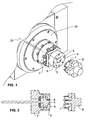
- the figure 1 illustrates the spindle (20) of a machine tool equipped with a workpiece holder (7) for carrying out the invention.
- the piece holder comprises two elements (3, 4) for mounting and positioning the blank (1). These two elements form a "divider", that is to say a set of two workpieces which will be, after the separation of the desired part from the rest of the blank, used to manipulate the two parts separately.
- the two elements (3 and 4) are round and coaxial with the axis (21) of rotation of the spindle (20), but they could also be of any shape, and non-coaxial with the axis of rotation, or even non-coaxial to each other.
- the shape and arrangement of the elements depend on the shape of the workpiece being machined and that of the wafer of which the desired workpiece is made.
- the figure 1 illustrates the course of the first step of a method according to the invention.
- the plate (1) which is provided with positioning holes, is provided by the gripper (8), is placed on the outer mounting element (3) of the workpiece carrier (7).
- This element (3) is provided with pins (5) for positioning which correspond to the holes of the wafer (1).
- the surface of the inner part of the divider (the element 4) is flush with that of the outer zone (the element 3).
- the inner element (4) is also provided with positioning pins (6), but these pins (6) are retractable, and during this first step, are retracted flush with or under the surface of the inner element ( 4).
- the figure 2 illustrates a section view of the representation of the figure 1 . From this figure we see a part of the mechanism for advancing or retracting the inner element (4) relative to the outer element (3). Although these figures show a carrier in which the inner portion (4) is retractable relative to the outer portion (3), it would be possible to reverse such that the outer member (3) is retracted relative to the inner member (4), or even to equip both with retraction means relative to each other, or to the workpiece holder (7).
- FIG 3 illustrates a second orthographic view of the representation of Figures 1 and 2 . From this figure, we see the holes (19) of positioning of the blank (1) ready to mount on the workpiece holder (7, 3, 4).
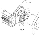
- the figure 4 shows the second step of the process.
- the blank is clamped on the workpiece holder (7) by a flange clamp (10) retractable in a plane substantially orthogonal to the axis (21) of rotation of the spindle (20).
- the side clamp (10) presses the part of the blank (1) which is not part of the desired part (here called the remaining part) - the outer part in this example - to hold the blank (1) in position during machining.
- the figure 4 also shows the machining of the part (called useful part here) of the blank (1) intended to become the desired part.
- the machining can include any kind of machining operations, such as grinding, milling, drilling or turning, for example, alone or in combination.
- a second set of holes (9) is machined in the useful part, which will help later to hold the useful part (2) in position on the workpiece carrier (7).
- the machining may also include partial cutting - a blank contouring to facilitate and simplify the subsequent cutting of the useful part (2) in the blank (1).
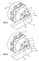
- the figure 5 illustrates the third step of the method - the flank (10) is retracted, and then a rotary retractable support (12) is set up to press the useful part (2) of the blank (1) against the workpiece holder (7, 4) to hold it in place during cutting.
- the figure 6 illustrates the fourth step of the process - the inner member (4) of the workpiece carrier (7) is advanced a little to press against the support (12), and the pins (6) of the inner element (4) come out and combine in the holes (9) machined in the second step.
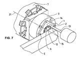
- the figure 7 illustrates the fifth step of the method, wherein the "bridges" (15) attaching the useful part (2) to the remaining part of the blank are removed by drilling, for example, or by other kinds of machining.
- the useful part (2) is now machined and detached from the rest of the blank (1).
- the useful part (2) is thus held at the workpiece holder (7), more precisely to the retractable inner member (4) of the workpiece carrier (7) by the support (12) and the pins (6) of the inner element (4).
- the Figures 8 to 10 illustrate the sixth step of the process - removing the remaining part (16) of the blank (1), and preparing the useful part (2) for finishing.
- the remaining part (16) is removed by the gripper (8) already used in the first step to put the blank (1) on the workpiece carrier (7). From these figures we also see the roughness and the remains of the "bridges" (15a) that will be removed in a finishing operation.
- the retractable element (4) of the workpiece carrier (7) is advanced, protruding from the outer element (3), to allow unhindered machining by the outer element (3) and its pins ( 6).
- Finishing being the eighth step of the process, is illustrated in the figure 11 .
- the useful part (2) of the blank is always held in place by the support (12) and the pins (6).
- the finishing is accomplished, by turning, with a finishing tool (17).
- the figure 12 illustrates the removal of the machined part (2) from the workpiece carrier (7, 4) by a suitable gripper (18), and the figure 13 watch how, after removal of the machined part (2), the retractable element (4) of the workpiece carrier (7), and its pins (6), are returned in preparation for the installation of the next workpiece to be machined .
- Step 1
- the inner pusher (4) is flush with the bearing zone (4), pins (6) retracted.
- the retractable flank (10) comes to hold the blank (1).
- the machined part (2) is not yet detached.
- the pusher (4) inside the divider (3, 4) advances one notch.
- the pins (6) come to hold the plate (2) but the pusher (4) is still not at the end of the race.
- the support (12) on the front face of the workpiece (2) is still in action.
- the axis (21) of the divider (3, 4) presents consecutively in front of the spindle (20) the two points (15) that remain to be machined to detach the part ( 2).
- the gripper (8) comes to find the contour of the tray (16) while the plate (2) remains on its pins.
- the inner pusher (4) comes to the end of stroke to clear the plate (2) farther than the pins (6) fixed on the divider (3, 4).
- the piece (2) is rotated (using the support 12 whose end is guided in rotation).
- the gripper 18 picks up the finished piece (2).
- the inner pusher (4) returns to the starting position, pins (6) retracted.
Abstract
Description
La présente invention se rapporte au domaine technique général de l'usinage de pièces, et plus particulièrement, mais non exclusivement, au domaine technique de l'usinage d'une platine à partir d'une pièce brute telle qu'une plaquette.The present invention relates to the general technical field of machining parts, and more particularly, but not exclusively, to the technical field of machining a plate from a blank such as a wafer.
Par usinage on désigne un processus général qui peut comprendre toute sorte d'usinage, tel que le meulage, le fraisage, le tournage ou le perçage, par exemple, seul ou en combinaison.By machining is meant a general process which may include any kind of machining, such as grinding, milling, turning or drilling, for example, alone or in combination.
Historiquement, l'usinage des petites pièces, par exemple des petites rondelles comme les platines de montres, est effectué à partir d'une plaquette plus grande que la pièce désirée, et souvent d'une forme carrée, car cette forme est plus facile à manipuler et à orienter qu'une pièce ronde.Historically, the machining of small parts, for example small washers such as watch decks, is made from a wafer larger than the desired piece, and often of a square shape, because this shape is easier to manipulate and guide a round piece.
La plaquette carrée est typiquement fabriquée ayant des perçages ou des échancrures qui permettent un positionnement précis sur des goupilles saillantes d'un porte-pièce de la machine-outil.The square wafer is typically manufactured having holes or indentations that allow precise positioning on protruding pins of a workpiece carrier of the machine tool.
L'usinage de la platine se déroule par exemple en deux stades successifs : usinage d'une partie de la plaquette, et le découpage de la partie dans la plaquette.The machining of the platen takes place for example in two successive stages: machining a portion of the wafer, and the cutting of the portion in the wafer.
Dans le premier stade, la plaquette vierge est positionnée sur un porte-pièce. Une fois positionnée et serrée en position, la plaquette (ou au moins la partie d'intérêt) est usinée par fraisage, meulage, perçage ou tournage, par exemple, avec des outils connus. Le porte-pièce est adapté spécialement pour maintenir la forme particulière de la plaquette.In the first stage, the blank wafer is positioned on a workpiece. Once positioned and tightened in position, the wafer (or at least the part of interest) is machined by milling, grinding, drilling or turning, for example, with known tools. The holder is specially adapted to maintain the particular shape of the wafer.
Le deuxième stade est le découpage de la platine dans la plaquette. La plaquette est transférée à un deuxième porte-pièce, adapté à maintenir la partie à découper de la plaquette (c'est-à-dire la pièce destinée à devenir la platine) sans perturber le découpage. Le découpage même est effectué par un processus de coupe approprié, comme connu de l'art ; de fraisage, tournage, sciage, ou de coupage par laser, par exemple. Le reste de la plaquette (c'est-à-dire la partie non-utile) tombe de la zone d'usinage ou est enlevée mécaniquement, dès la fin du découpage.The second stage is the cutting of the platinum in the wafer. The wafer is transferred to a second carrier, adapted to maintain the cutting portion of the wafer (that is to say the part to become the platen) without disturbing the cutting. The cutting itself is carried out by an appropriate cutting process, as known in the art; milling, turning, sawing, or laser cutting, for example. The remainder of the wafer (ie the non-useful part) falls from the machining area or is mechanically removed as soon as the cutting is complete.
Un processus de finissage ultérieur est normalement aussi nécessaire, par exemple pour affiler les arêtes grossières du découpage.A subsequent finishing process is normally also necessary, for example to sharpen the rough edges of the cut.
Finalement, la platine usinée est enlevée du porte-pièce.Finally, the machined plate is removed from the workpiece holder.
Ces procédés connus possèdent l'inconvénient qu'ils nécessitent deux posages et deux étapes distinctes avec un déplacement de la plaquette entre les deux posages, ce qui apporte une augmentation importante du temps d'usinage.These known methods have the disadvantage that they require two positions and two distinct stages with a movement of the wafer between the two positions, which brings a significant increase in machining time.
Un autre inconvénient des procédés de l'état de la technique est que le déplacement de la plaquette pendant l'usinage (entre les premier et deuxième portes-pièce par exemple) admet une imprécision importante de positionnement pour l'usinage des pièces à très haute précision.Another disadvantage of the methods of the state of the art is that the displacement of the wafer during machining (between the first and second workpiece for example) admits a significant inaccuracy of positioning for machining parts at very high precision.
Un autre inconvénient est la difficulté de tenir et/ou enlever la partie restante de la plaquette pendant l'étape de découpage. Dans les systèmes connus, cette partie restante n'est pas supportée et peut tomber du porte-pièce dès qu'elle se détache de la partie supportée (la platine usinée). Cette pièce restante, libre et mobile dans les environs de la pièce usinée, peut bien l'abîmer. Un mécanisme pour enlever la pièce restante serait souhaitable, mais un tel mécanisme est pratiquement difficile à réaliser sans empêcher le mouvement de l'outil de découpage.Another disadvantage is the difficulty of holding and / or removing the remaining portion of the wafer during the cutting step. In known systems, this remaining part is not supported and can fall from the workpiece as soon as it is detached from the supported part (the machined plate). This remaining piece, free and mobile in the vicinity of the machined piece, can damage it. A mechanism for removing the remaining piece would be desirable, but such a mechanism is practically difficult to achieve without preventing the movement of the cutting tool.
Un porte-piece selon la préambule de la revendication 1 et un procédé selon la préambule de la revendication 6 sont décrits dans
Un objet que la présente invention vise par conséquent à proposer est un nouveau procédé d'usinage d'une pièce désirée (par exemple d'une platine de montre) à partir d'une pièce brute qui se déroule plus rapidement, qui élimine la nécessité de déplacer la plaquette d'un porte-pièce à un autre, et dans lequel la partie restante peut être enlevée sans abîmer la platine et sans nécessiter des mécanismes spéciaux.An object that the present invention is therefore intended to provide is a new method of machining a desired part (for example a watch plate) from a piece of work that takes place more quickly, eliminating the need moving the wafer from one workpiece to another, and wherein the remaining portion can be removed without damaging the platen and without requiring special mechanisms.
Un autre objet de l'invention est un procédé d'usinage à haute précision.Another object of the invention is a high precision machining method.
Un autre objet que l'invention vise à proposer est un porte-pièce qui permet la réalisation de ce procédé, en permettant le positionnement de la plaquette brute et le positionnement, dès qu'elles se sont détachées par le découpage de la partie usinée et la partie restante.Another object that the invention aims to propose is a workpiece which allows the realization of this method, allowing the positioning of the raw wafer and positioning, as soon as they are detached by the cutting of the machined part and the remaining part.
A cet effet, l'invention a pour objet un porte-pièce pour maintenir une pièce brute en position pendant un usinage dans une machine-outil et sous commande d'un logiciel de commande afin de produire une pièce désirée, la pièce brute comprenant une partie utile, étant la partie destinée à être usinée et puis découpée pour fournir la pièce désirée, et une partie restante, destinée à ne pas faire partie de la pièce désirée,
le porte-pièce comprenant :
- des moyens de montage et positionnement de la pièce brute, un des moyens de montage et positionnement, dit premier élément, disposé pour tenir en position la partie utile de la pièce brute, et un autre des moyens de montage et positionnement, dit second élément, disposé pour tenir en position la partie restante de la pièce brute,
- au moins un desdits premier et second éléments étant déplaçable sous commande dudit logiciel de commande, tel que, dès le découpage de la partie utile de la pièce brute, le premier élément peut être avancé relatif au second élément pour faciliter un finissage de la partie utile montée sur le premier élément.
the holder comprising:
- means for mounting and positioning the blank, one of the mounting and positioning means, said first element, arranged to hold in position the useful part of the blank, and another of the mounting and positioning means, said second element, arranged to hold in position the remaining part of the blank,
- at least one of said first and second elements being displaceable under control of said control software, such that, as soon as the useful part of the blank is cut, the first element can be advanced relative to the second element to facilitate a finishing of the useful part mounted on the first element.
L'invention a également pour objet un procédé de production d'une pièce désirée depuis une pièce brute, la pièce brute comprenant une partie utile, étant la partie de la pièce brute destinée à être usinée et puis découpée pour fournir la pièce désirée, et une partie restante, étant la partie de la pièce brute destinée à ne pas faire partie de la pièce désirée, le procédé étant réalisé sous commande d'un logiciel de commande dans une machine-outil comprenant un porte-pièce, le porte-pièce comprend un premier élément pour tenir la partie utile de la pièce brute, et un second élément pour tenir la partie restante de la pièce brute, lesdits premier et second éléments étant susceptibles d'être déplacés, relatifs l'un à l'autre, selon l'axe de rotation, et sous commande du logiciel de commande, le procédé comprenant les étapes suivantes :
- une première étape de positionnement de la pièce brute sur le porte-pièce,
- une seconde étape de serrage de la pièce brute en position sur le porte-pièce, en un serrant la partie restante au second élément du porte-pièce,
- une troisième étape d'usinage de la partie utile de la pièce brute, la troisième étape comprenant un découpage partiel de ladite partie utile dans la pièce brute, telle que la partie utile et la partie restante ne sont attachées que par des régions non-découpées, dites ponts, de la pièce brute,
- une quatrième étape de serrage de la partie utile au premier élément,
- une cinquième étape d'enlèvement des ponts, et ainsi de la désolidarisation des parties utiles et restantes,
- une sixième étape de l'enlèvement de la partie restante du porte-pièce,
- une septième étape de déplacement du premier élément du porte-pièce telle que la partie utile de la pièce brute s'éloigne du second élément, et
- une huitième étape d'usinage postérieure de la partie utile.
- a first step of positioning the blank on the workpiece,
- a second step of clamping the blank in position on the workpiece, by clamping the remaining part to the second element of the workpiece,
- a third step of machining the useful part of the blank, the third step comprising a partial cutting of said useful part in the blank, such that the useful part and the remaining part are attached only by non-cut areas , say bridges, of the blank,
- a fourth step of clamping the useful part to the first element,
- a fifth step of removing the bridges, and thus the separation of the useful and remaining parts,
- a sixth step of removing the remaining part of the carrier,
- a seventh step of moving the first element of the workpiece such that the useful part of the blank part moves away from the second element, and
- an eighth stage of posterior machining of the useful part.
Quelques variantes de l'invention sont définies dans les revendications dépendantes ci-annexées.Some variants of the invention are defined in the dependent claims appended hereto.
L'invention et ses avantages seront mieux compris à la lecture de la description ci-après faite à titre d'exemple non limitatif, en référence aux figures annexées qui représentent :
- la
figure 1 , illustre un exemple d'une broche de tournage d'une machine-outil, avec un porte-pièce selon l'invention, et un moyen de positionnement d'une pièce à usiner sur le porte-pièce, prêt à exécuter la première étape d'un procédé selon l'invention. - la
figure 2 , illustre une vue section du porte-pièce et le moyen du positionnement de lafigure 1 . - la
figure 3 , illustre une vue orthographique du porte-pièce et du moyen de positionnement de lafigure 1 . - la
figure 4 , illustre une vue orthographique du porte-pièce, un moyen de serrage et des moyens d'usinage pour l'exécution des seconde et troisième étapes d'un procédé selon l'invention. - les
figures 5 et 6 , illustrent une vue orthographique d'une pièce montée sur le porte-pièce, et des moyens de positionnement et de serrage pour l'exécution de la quatrième étape d'un procédé selon l'invention. - la
figure 7 , illustre une vue orthographique de l'enlèvement, dans la cinquième étape de procédé, des « ponts » restants après le décolletage partiel de la quatrième étape. - la
figure 8 , illustre une vue orthographique de l'éloignement de la pièce restante (non-utile) du porte-pièce dans la sixième étape du procédé. - la
figure 9 , illustre une vue section defigure 8 . - la
figure 10 , illustre une vue orthographique du déplacement en avant du premier élément du porte-pièce, selon la septième étape du procédé, afin de permettre un finissage de la pièce utile. - la
figure 11 , illustre une vue orthographique d'un usinage selon la huitième étape du procédé. - la
figure 12 , illustre une vue orthographique de l'enlèvement de la pièce usinée. - la
figure 13 , illustre une vue orthographique de l'escamotage ultérieur du premier élément de porte-pièce et l'escamotage des goupilles dans le premier élément.
- the
figure 1 illustrates an example of a turning spindle of a machine tool, with a workpiece according to the invention, and a positioning means of a workpiece on the workpiece holder, ready to perform the first step of a method according to the invention. - the
figure 2 , illustrates a section view of the carrier and the means of positioning thefigure 1 . - the
figure 3 , illustrates an orthographic view of the workpiece holder and the positioning means of thefigure 1 . - the
figure 4 , illustrates an orthographic view of the workpiece carrier, a clamping means and machining means for carrying out the second and third steps of a method according to the invention. - the
Figures 5 and 6 , illustrate an orthographic view of a workpiece mounted on the workpiece, and positioning and clamping means for performing the fourth step of a method according to the invention. - the
figure 7 , illustrates an orthographic view of the removal, in the fifth process step, of the remaining "bridges" after partial turning of the fourth step. - the
figure 8 , illustrates an orthographic view of the remoteness of the remaining (non-useful) workpiece part in the sixth process step. - the
figure 9 , illustrates a section view offigure 8 . - the
figure 10 , illustrates an orthographic view of the displacement in front of the first element of the workpiece holder, according to the seventh step of the method, to allow a finishing of the useful part. - the
figure 11 , illustrates an orthographic view of a machining according to the eighth step of the method. - the
figure 12 , illustrates an orthographic view of the removal of the machined part. - the
figure 13 , illustrates an orthographic view of the subsequent retraction of the first workpiece member and the retraction of the pins in the first member.
Les éléments structurellement et fonctionnellement identiques et présents sur plusieurs figures distinctes, sont affectés d'une seule et même référence.The structurally and functionally identical elements present in several distinct figures are assigned a single reference.
La
Dans l'exemple représenté dans la
La
Cette disposition de goupilles et trous de positionnement n'est qu'une des nombreuses possibilités pour maintenir la plaquette étant usinée en position sur le porte-pièce (7). On pourrait également utiliser quelconques sortes de formes correspondantes qui peuvent servir à positionner précisément la pièce (1) sur la surface du porte-pièce (7).This arrangement of pins and positioning holes is only one of many possibilities to maintain the wafer being machined in position on the workpiece holder (7). We could also use any kinds of corresponding shapes that can be used to precisely position the workpiece (1) on the surface of the workpiece carrier (7).
La
La
La
La
La
La
La
Les
Le finissage, étant la huitième étape du procédé, est illustré dans la
La
Les étapes du procédé sont décrites en forme sommaire ci-après:The process steps are described in summary form below:
Chargement de la barquette (1) sur les goupilles extérieures (5) du diviseur (3, 4) à l'aide du préhenseur (8).Load the tray (1) on the outer pins (5) of the divider (3, 4) using the gripper (8).
Le poussoir intérieur (4) est à fleur de la zone d'appui (4), goupilles (6) rentrées.The inner pusher (4) is flush with the bearing zone (4), pins (6) retracted.
Le serre-flanc escamotable (10) vient maintenir la pièce brute (1).The retractable flank (10) comes to hold the blank (1).
Fraisage et perçage de la face de la pièce et ébauche du contournement.Milling and drilling the face of the workpiece and roughing the workaround.
La pièce usinée (2) n'est pas encore détachée.The machined part (2) is not yet detached.
Retrait du serre-flanc (10) et mise en place d'un appui (12) escamotable rotatif qui presse la pièce usinée (2).Removing the clamp (10) and setting up a support (12) rotatable retractable pressing the workpiece (2).
Le poussoir (4) à l'intérieur du diviseur (3, 4) avance d'un cran.The pusher (4) inside the divider (3, 4) advances one notch.
Ce sont alors les goupilles (6) correspondants aux trous (9) de la platine (2) qui sortent.It is then the pins (6) corresponding to the holes (9) of the plate (2) that come out.
Les goupilles (6) viennent tenir la platine (2) mais le poussoir (4) n'est toujours pas en fin de course.The pins (6) come to hold the plate (2) but the pusher (4) is still not at the end of the race.
L'appui (12) sur la face avant de la pièce usinée (2) est toujours en action.The support (12) on the front face of the workpiece (2) is still in action.
Avec l'appui (12) toujours en place, l'axe (21) du diviseur (3, 4) vient présenter consécutivement devant la broche (20) les deux points (15) qu'ils restent à usiner pour détacher la pièce (2).With the support (12) still in place, the axis (21) of the divider (3, 4) presents consecutively in front of the spindle (20) the two points (15) that remain to be machined to detach the part ( 2).
Le préhenseur (8) vient chercher le contour de la barquette (16) alors que la platine (2) reste sur ses goupilles.The gripper (8) comes to find the contour of the tray (16) while the plate (2) remains on its pins.
Le poussoir intérieur (4) vient en fin de course pour dégager la platine (2) plus loin que les goupilles (6) fixées sur le diviseur (3, 4).The inner pusher (4) comes to the end of stroke to clear the plate (2) farther than the pins (6) fixed on the divider (3, 4).
La pièce (2) est tournée (à l'aide de l'appui 12 dont l'extrémité est guidée en rotation).The piece (2) is rotated (using the
Le préhenseur 18 vient chercher la pièce finie (2).The
Le poussoir intérieur (4) revient en position de départ, goupilles (6) rentrées.The inner pusher (4) returns to the starting position, pins (6) retracted.
Claims (10)
- Workpiece holder (7) for holding a raw piece (1) in position during a machining in a machine tool and under control of a control software in order to produce a desired piece,
the raw piece (1) comprising a useful part (2), being the part intended to be machines and then cut out to provide the desired piece, and a remaining part (16), intended not to form part of the desired piece,
the workpiece holder comprising means (3, 4) of mounting and positioning of the raw piece (1),
the workpiece holder (7) comprising:one of means of mounting and positioning, referred to as first element (4), disposed to hold in position the useful part (2) of the raw piece (1),another means of mounting and positioning, referred to as second element (3), disposed to hold in position the remaining part (16) of the raw piece (1), and the workpiece holder being characterised in thatat least one of said first and second elements (3, 4) is displaceable under the control of said control software, such that, from the cutting out of the useful part (2) of the raw piece (1), the first element (4) can be advanced relative to the second element (3) to facilitate a finishing of the useful part (2) mounted on the first element (4). - Workpiece holder (7) according to claim 1, wherein :the first element (4) comprises first locating means (locating studs) (6) to engage in second inverse locating means (locating holes) (9) of the useful part (2) of the raw piece (1).
- Workpiece holder (7) according to claim 2, wherein:the said first locating means (6) comprise first pins protruding from the first element (4).
- Workpiece holder according to one of the claims 1 to 3, wherein
the first pins are retractable between a first position, referred to as retracted position, where they do not surpass the first surface, and a second position, referred to as projecting position, where they project from the first element (4). - Workpiece holder according to one of the claims 1 to 4, wherein the first pins comprise means of clamping the useful part (2) to the first element (4) of the workpiece holder (7).
- Method of production of a desired piece from a raw piece (1), the raw piece (1) comprising a useful part (2), being the part of the raw piece intended to be machined and then cut out to provide the desired piece, and a remaining part (16), being the part of the raw piece intended not to form part of the desired piece,
the method being carried out under the control of a control software in a machine tool,
the machine tool comprising a workpiece holder (7),
the method comprising a first step of positioning of <the> raw piece (1) on the workpiece holder (7),
a second step of clamping of the raw piece (1) in position on the workpiece holder (7),
a third step of machining of the useful part (2) of the raw piece (1),
the clamping of the said second step being a clamping of the remaining part (16) to the second element (3) of the workpiece holder (7),
the said third step comprising a partial cutting out of the said useful part in the raw piece (1), such that the useful part and the remaining part (16) are attached only by regions not cut out (15), referred to as "bridges", of the raw piece (1),
the method further comprising:a fourth step of clamping of the useful part to the first element (4),a fifth step of removal of the "bridges", and thus of separating of the useful and remaining parts,a sixth step of removal of the remaining part (16) from the workpiece holder (7),the method being characterised in that:the workpiece holder (7) comprises a first element (4) for holding the useful part of the raw piece (1), and a second element (3) for holding the remaining part (16) of the raw piece (1), the said first and second elements (4 and 3) being capable of being displaced, one relative to the other, along the axis of rotation, and under control of control software, and in that the method comprisesa seventh step of displacement of the first element (4) of the workpiece holder (7) such that the useful part of the raw piece moves away from the second element (3), andan eighth step of subsequent machining of the useful part. - Production method according to claim 6, wherein the said first element (4) and the said useful part (2) of the raw piece (1) comprise one of the complementary locating means (locating stud/locating hole) (6, 9).
- Production method according to claim 7, wherein the complementary locating means (locating stud/locating hole) of the first element (4) comprise positioning pins, the said pins being displaceable between a first arrangement retracted in the first element (4) and a second arrangement projecting from the first element (4),
and in which the complementary locating means (locating stud/locating hole) of the useful part (2) of the raw piece (1) comprise perforations and/or notches for a precise positioning of the useful piece on the the first element when the pins project from the first element. - Production method according to claim 8, wherein the fourth step comprises a displacement of the pins between the retracted arrangement and the projecting arrangement, such that the useful part can be held in position from the fifth to the eighth step.
- Production method according to claim 6, wherein the eighth step comprises a machining of the edges of the first part to remove any rough areas (15a) caused during the third and/or fifth steps.
Priority Applications (3)
| Application Number | Priority Date | Filing Date | Title |
|---|---|---|---|
| ES08020064T ES2370933T3 (en) | 2008-11-18 | 2008-11-18 | MACHINING OF PARTS WITH A SINGLE HOLDING OPERATION. |
| AT08020064T ATE513255T1 (en) | 2008-11-18 | 2008-11-18 | PROCESSING WORKPIECES WITH A SINGLE CLAMPING OPERATION |
| EP08020064A EP2187273B1 (en) | 2008-11-18 | 2008-11-18 | Machining of parts with a single tightening operation |
Applications Claiming Priority (1)
| Application Number | Priority Date | Filing Date | Title |
|---|---|---|---|
| EP08020064A EP2187273B1 (en) | 2008-11-18 | 2008-11-18 | Machining of parts with a single tightening operation |
Publications (2)
| Publication Number | Publication Date |
|---|---|
| EP2187273A1 EP2187273A1 (en) | 2010-05-19 |
| EP2187273B1 true EP2187273B1 (en) | 2011-06-15 |
Family
ID=40550199
Family Applications (1)
| Application Number | Title | Priority Date | Filing Date |
|---|---|---|---|
| EP08020064A Active EP2187273B1 (en) | 2008-11-18 | 2008-11-18 | Machining of parts with a single tightening operation |
Country Status (3)
| Country | Link |
|---|---|
| EP (1) | EP2187273B1 (en) |
| AT (1) | ATE513255T1 (en) |
| ES (1) | ES2370933T3 (en) |
Families Citing this family (2)
| Publication number | Priority date | Publication date | Assignee | Title |
|---|---|---|---|---|
| EP3639972B1 (en) * | 2018-10-17 | 2023-05-24 | ETA SA Manufacture Horlogère Suisse | Universal gripper for timepiece washers |
| CN109634087B (en) * | 2018-12-26 | 2020-08-25 | 厦门理工学院 | Positive plate rotating mechanism of clock |
Family Cites Families (4)
| Publication number | Priority date | Publication date | Assignee | Title |
|---|---|---|---|---|
| CH357942A (en) * | 1960-09-17 | 1961-10-31 | Hugo Allemann Ag | Semi-automatic machine for drilling, tapping and milling work against the outer surface of a plate-shaped work piece |
| CH409584A (en) * | 1963-12-06 | 1966-03-15 | Hauser Ag Henri | Processing machine and use of the same |
| KR920009967B1 (en) * | 1990-11-01 | 1992-11-09 | 삼성전자 주식회사 | Clamping device |
| DE602007001064D1 (en) * | 2006-11-03 | 2009-06-18 | Michel Yerly | Holding device for workpiece |
-
2008
- 2008-11-18 ES ES08020064T patent/ES2370933T3/en active Active
- 2008-11-18 EP EP08020064A patent/EP2187273B1/en active Active
- 2008-11-18 AT AT08020064T patent/ATE513255T1/en active
Also Published As
| Publication number | Publication date |
|---|---|
| ATE513255T1 (en) | 2011-07-15 |
| EP2187273A1 (en) | 2010-05-19 |
| ES2370933T3 (en) | 2011-12-23 |
Similar Documents
| Publication | Publication Date | Title |
|---|---|---|
| EP1796871B9 (en) | Device for clamping a tool insert in a grinding machine | |
| JP5746734B2 (en) | Umbrella gear cutting tool with cutter bar and method of using the same | |
| US8672592B2 (en) | Milling collet having pull-out preventer for retaining a fluted milling tool | |
| FR2956334A1 (en) | TOOL FOR MACHINING MATERIALS BY REMOVING CHIPS AND METHOD FOR GUIDING CUTTING INSERTS INTO SUCH A TOOL | |
| EP2187273B1 (en) | Machining of parts with a single tightening operation | |
| FR2631865A1 (en) | ||
| EP1829638B1 (en) | Rotating cutting tool comprising two cutting portions with opposed cutting direction | |
| EP2500137B1 (en) | Rapid clamping pin | |
| EP1442833B1 (en) | Clamping crampon and method for clamping a workpiece with such clamping crampons | |
| EP2233247B1 (en) | High-production standalone machining centre taking parts vertically | |
| EP2801427B1 (en) | Anti-vibration mounting and method for milling a metal part | |
| FR2523884A1 (en) | MACHINING TOOL COMPRISING A CUTTING PLATE SEAT AND A REMOVABLE CUTTING PLATE | |
| FR2523010A1 (en) | Method of milling external or internal surfaces of cylindrical work - uses free wheel with helical teeth moved axially through or over work | |
| EP2688703B1 (en) | Process and device for milling-surfacing | |
| FR3070890B1 (en) | WORK PLATINUM WITH TWO TOOL GAMES ON ONE SIDE | |
| FR3067956B1 (en) | DEVICE FOR ADAPTING A SOFT BIT ON A HARD BODY | |
| EP0949030A1 (en) | Rotating cutting tool | |
| EP2382396B1 (en) | Method for positioning mechanical parts | |
| FR2931382A1 (en) | Cutting device for use in cutting machine, has elastic maintaining units to maintain each cut assembly in one of notch of tool support, where units take back cut assembly in separated position of sidewall of notch of tool support | |
| EP2943298B1 (en) | Positioning of cutting blades on a press frame | |
| FR3058080A1 (en) | TANGENTIAL MACHINING ELEMENT | |
| CH346182A (en) | Method for decorating timepiece elements and apparatus for implementing this method | |
| FR3061526A1 (en) | SUPPORT PLATE FOR BRAKE LINING | |
| JP2004098249A (en) | Pin mirror cutter | |
| EP3532224A1 (en) | Tangential machining element |
Legal Events
| Date | Code | Title | Description |
|---|---|---|---|
| PUAI | Public reference made under article 153(3) epc to a published international application that has entered the european phase |
Free format text: ORIGINAL CODE: 0009012 |
|
| AK | Designated contracting states |
Kind code of ref document: A1 Designated state(s): AT BE BG CH CY CZ DE DK EE ES FI FR GB GR HR HU IE IS IT LI LT LU LV MC MT NL NO PL PT RO SE SI SK TR |
|
| AX | Request for extension of the european patent |
Extension state: AL BA MK RS |
|
| 17P | Request for examination filed |
Effective date: 20101117 |
|
| GRAP | Despatch of communication of intention to grant a patent |
Free format text: ORIGINAL CODE: EPIDOSNIGR1 |
|
| AKX | Designation fees paid |
Designated state(s): AT BE BG CH CY CZ DE DK EE ES FI FR GB GR HR HU IE IS IT LI LT LU LV MC MT NL NO PL PT RO SE SI SK TR |
|
| GRAS | Grant fee paid |
Free format text: ORIGINAL CODE: EPIDOSNIGR3 |
|
| GRAA | (expected) grant |
Free format text: ORIGINAL CODE: 0009210 |
|
| AK | Designated contracting states |
Kind code of ref document: B1 Designated state(s): AT BE BG CH CY CZ DE DK EE ES FI FR GB GR HR HU IE IS IT LI LT LU LV MC MT NL NO PL PT RO SE SI SK TR |
|
| REG | Reference to a national code |
Ref country code: GB Ref legal event code: FG4D Free format text: NOT ENGLISH Ref country code: CH Ref legal event code: EP |
|
| REG | Reference to a national code |
Ref country code: IE Ref legal event code: FG4D Free format text: LANGUAGE OF EP DOCUMENT: FRENCH |
|
| REG | Reference to a national code |
Ref country code: DE Ref legal event code: R096 Ref document number: 602008007548 Country of ref document: DE Effective date: 20110804 |
|
| REG | Reference to a national code |
Ref country code: NL Ref legal event code: VDEP Effective date: 20110615 |
|
| REG | Reference to a national code |
Ref country code: CH Ref legal event code: NV Representative=s name: BOVARD AG |
|
| PG25 | Lapsed in a contracting state [announced via postgrant information from national office to epo] |
Ref country code: LT Free format text: LAPSE BECAUSE OF FAILURE TO SUBMIT A TRANSLATION OF THE DESCRIPTION OR TO PAY THE FEE WITHIN THE PRESCRIBED TIME-LIMIT Effective date: 20110615 Ref country code: HR Free format text: LAPSE BECAUSE OF FAILURE TO SUBMIT A TRANSLATION OF THE DESCRIPTION OR TO PAY THE FEE WITHIN THE PRESCRIBED TIME-LIMIT Effective date: 20110615 Ref country code: NO Free format text: LAPSE BECAUSE OF FAILURE TO SUBMIT A TRANSLATION OF THE DESCRIPTION OR TO PAY THE FEE WITHIN THE PRESCRIBED TIME-LIMIT Effective date: 20110915 Ref country code: SE Free format text: LAPSE BECAUSE OF FAILURE TO SUBMIT A TRANSLATION OF THE DESCRIPTION OR TO PAY THE FEE WITHIN THE PRESCRIBED TIME-LIMIT Effective date: 20110615 |
|
| PG25 | Lapsed in a contracting state [announced via postgrant information from national office to epo] |
Ref country code: CY Free format text: LAPSE BECAUSE OF FAILURE TO SUBMIT A TRANSLATION OF THE DESCRIPTION OR TO PAY THE FEE WITHIN THE PRESCRIBED TIME-LIMIT Effective date: 20110615 Ref country code: LV Free format text: LAPSE BECAUSE OF FAILURE TO SUBMIT A TRANSLATION OF THE DESCRIPTION OR TO PAY THE FEE WITHIN THE PRESCRIBED TIME-LIMIT Effective date: 20110615 Ref country code: SI Free format text: LAPSE BECAUSE OF FAILURE TO SUBMIT A TRANSLATION OF THE DESCRIPTION OR TO PAY THE FEE WITHIN THE PRESCRIBED TIME-LIMIT Effective date: 20110615 Ref country code: GR Free format text: LAPSE BECAUSE OF FAILURE TO SUBMIT A TRANSLATION OF THE DESCRIPTION OR TO PAY THE FEE WITHIN THE PRESCRIBED TIME-LIMIT Effective date: 20110916 Ref country code: FI Free format text: LAPSE BECAUSE OF FAILURE TO SUBMIT A TRANSLATION OF THE DESCRIPTION OR TO PAY THE FEE WITHIN THE PRESCRIBED TIME-LIMIT Effective date: 20110615 |
|
| REG | Reference to a national code |
Ref country code: ES Ref legal event code: FG2A Ref document number: 2370933 Country of ref document: ES Kind code of ref document: T3 Effective date: 20111223 |
|
| PG25 | Lapsed in a contracting state [announced via postgrant information from national office to epo] |
Ref country code: NL Free format text: LAPSE BECAUSE OF FAILURE TO SUBMIT A TRANSLATION OF THE DESCRIPTION OR TO PAY THE FEE WITHIN THE PRESCRIBED TIME-LIMIT Effective date: 20110615 |
|
| REG | Reference to a national code |
Ref country code: IE Ref legal event code: FD4D |
|
| PG25 | Lapsed in a contracting state [announced via postgrant information from national office to epo] |
Ref country code: IS Free format text: LAPSE BECAUSE OF FAILURE TO SUBMIT A TRANSLATION OF THE DESCRIPTION OR TO PAY THE FEE WITHIN THE PRESCRIBED TIME-LIMIT Effective date: 20111015 Ref country code: IE Free format text: LAPSE BECAUSE OF FAILURE TO SUBMIT A TRANSLATION OF THE DESCRIPTION OR TO PAY THE FEE WITHIN THE PRESCRIBED TIME-LIMIT Effective date: 20110615 Ref country code: PT Free format text: LAPSE BECAUSE OF FAILURE TO SUBMIT A TRANSLATION OF THE DESCRIPTION OR TO PAY THE FEE WITHIN THE PRESCRIBED TIME-LIMIT Effective date: 20111017 Ref country code: CZ Free format text: LAPSE BECAUSE OF FAILURE TO SUBMIT A TRANSLATION OF THE DESCRIPTION OR TO PAY THE FEE WITHIN THE PRESCRIBED TIME-LIMIT Effective date: 20110615 Ref country code: EE Free format text: LAPSE BECAUSE OF FAILURE TO SUBMIT A TRANSLATION OF THE DESCRIPTION OR TO PAY THE FEE WITHIN THE PRESCRIBED TIME-LIMIT Effective date: 20110615 |
|
| PG25 | Lapsed in a contracting state [announced via postgrant information from national office to epo] |
Ref country code: PL Free format text: LAPSE BECAUSE OF FAILURE TO SUBMIT A TRANSLATION OF THE DESCRIPTION OR TO PAY THE FEE WITHIN THE PRESCRIBED TIME-LIMIT Effective date: 20110615 Ref country code: SK Free format text: LAPSE BECAUSE OF FAILURE TO SUBMIT A TRANSLATION OF THE DESCRIPTION OR TO PAY THE FEE WITHIN THE PRESCRIBED TIME-LIMIT Effective date: 20110615 Ref country code: RO Free format text: LAPSE BECAUSE OF FAILURE TO SUBMIT A TRANSLATION OF THE DESCRIPTION OR TO PAY THE FEE WITHIN THE PRESCRIBED TIME-LIMIT Effective date: 20110615 |
|
| PLBE | No opposition filed within time limit |
Free format text: ORIGINAL CODE: 0009261 |
|
| STAA | Information on the status of an ep patent application or granted ep patent |
Free format text: STATUS: NO OPPOSITION FILED WITHIN TIME LIMIT |
|
| 26N | No opposition filed |
Effective date: 20120316 |
|
| BERE | Be: lapsed |
Owner name: ALMAC S.A. Effective date: 20111130 |
|
| PG25 | Lapsed in a contracting state [announced via postgrant information from national office to epo] |
Ref country code: DK Free format text: LAPSE BECAUSE OF FAILURE TO SUBMIT A TRANSLATION OF THE DESCRIPTION OR TO PAY THE FEE WITHIN THE PRESCRIBED TIME-LIMIT Effective date: 20110615 Ref country code: MC Free format text: LAPSE BECAUSE OF NON-PAYMENT OF DUE FEES Effective date: 20111130 |
|
| REG | Reference to a national code |
Ref country code: DE Ref legal event code: R097 Ref document number: 602008007548 Country of ref document: DE Effective date: 20120316 |
|
| REG | Reference to a national code |
Ref country code: FR Ref legal event code: ST Effective date: 20120731 |
|
| PG25 | Lapsed in a contracting state [announced via postgrant information from national office to epo] |
Ref country code: BE Free format text: LAPSE BECAUSE OF NON-PAYMENT OF DUE FEES Effective date: 20111130 |
|
| PG25 | Lapsed in a contracting state [announced via postgrant information from national office to epo] |
Ref country code: FR Free format text: LAPSE BECAUSE OF NON-PAYMENT OF DUE FEES Effective date: 20111130 |
|
| PG25 | Lapsed in a contracting state [announced via postgrant information from national office to epo] |
Ref country code: MT Free format text: LAPSE BECAUSE OF FAILURE TO SUBMIT A TRANSLATION OF THE DESCRIPTION OR TO PAY THE FEE WITHIN THE PRESCRIBED TIME-LIMIT Effective date: 20110615 |
|
| PGFP | Annual fee paid to national office [announced via postgrant information from national office to epo] |
Ref country code: ES Payment date: 20121127 Year of fee payment: 5 Ref country code: GB Payment date: 20121120 Year of fee payment: 5 |
|
| PG25 | Lapsed in a contracting state [announced via postgrant information from national office to epo] |
Ref country code: LU Free format text: LAPSE BECAUSE OF NON-PAYMENT OF DUE FEES Effective date: 20111118 |
|
| PG25 | Lapsed in a contracting state [announced via postgrant information from national office to epo] |
Ref country code: BG Free format text: LAPSE BECAUSE OF FAILURE TO SUBMIT A TRANSLATION OF THE DESCRIPTION OR TO PAY THE FEE WITHIN THE PRESCRIBED TIME-LIMIT Effective date: 20110915 |
|
| PG25 | Lapsed in a contracting state [announced via postgrant information from national office to epo] |
Ref country code: TR Free format text: LAPSE BECAUSE OF FAILURE TO SUBMIT A TRANSLATION OF THE DESCRIPTION OR TO PAY THE FEE WITHIN THE PRESCRIBED TIME-LIMIT Effective date: 20110615 |
|
| PG25 | Lapsed in a contracting state [announced via postgrant information from national office to epo] |
Ref country code: HU Free format text: LAPSE BECAUSE OF FAILURE TO SUBMIT A TRANSLATION OF THE DESCRIPTION OR TO PAY THE FEE WITHIN THE PRESCRIBED TIME-LIMIT Effective date: 20110615 |
|
| GBPC | Gb: european patent ceased through non-payment of renewal fee |
Effective date: 20131118 |
|
| PG25 | Lapsed in a contracting state [announced via postgrant information from national office to epo] |
Ref country code: GB Free format text: LAPSE BECAUSE OF NON-PAYMENT OF DUE FEES Effective date: 20131118 |
|
| REG | Reference to a national code |
Ref country code: AT Ref legal event code: MM01 Ref document number: 513255 Country of ref document: AT Kind code of ref document: T Effective date: 20131118 |
|
| PG25 | Lapsed in a contracting state [announced via postgrant information from national office to epo] |
Ref country code: AT Free format text: LAPSE BECAUSE OF NON-PAYMENT OF DUE FEES Effective date: 20131118 |
|
| REG | Reference to a national code |
Ref country code: ES Ref legal event code: FD2A Effective date: 20150327 |
|
| PG25 | Lapsed in a contracting state [announced via postgrant information from national office to epo] |
Ref country code: ES Free format text: LAPSE BECAUSE OF NON-PAYMENT OF DUE FEES Effective date: 20131119 |
|
| PGFP | Annual fee paid to national office [announced via postgrant information from national office to epo] |
Ref country code: IT Payment date: 20151124 Year of fee payment: 8 |
|
| PG25 | Lapsed in a contracting state [announced via postgrant information from national office to epo] |
Ref country code: IT Free format text: LAPSE BECAUSE OF NON-PAYMENT OF DUE FEES Effective date: 20161118 |
|
| PGFP | Annual fee paid to national office [announced via postgrant information from national office to epo] |
Ref country code: DE Payment date: 20191121 Year of fee payment: 12 |
|
| REG | Reference to a national code |
Ref country code: DE Ref legal event code: R119 Ref document number: 602008007548 Country of ref document: DE |
|
| PG25 | Lapsed in a contracting state [announced via postgrant information from national office to epo] |
Ref country code: DE Free format text: LAPSE BECAUSE OF NON-PAYMENT OF DUE FEES Effective date: 20210601 |
|
| PGFP | Annual fee paid to national office [announced via postgrant information from national office to epo] |
Ref country code: CH Payment date: 20231201 Year of fee payment: 16 |