EP2187273B1 - Bearbeitung von Werkstücken mit einem einzigen Klemmvorgang - Google Patents
Bearbeitung von Werkstücken mit einem einzigen Klemmvorgang Download PDFInfo
- Publication number
- EP2187273B1 EP2187273B1 EP08020064A EP08020064A EP2187273B1 EP 2187273 B1 EP2187273 B1 EP 2187273B1 EP 08020064 A EP08020064 A EP 08020064A EP 08020064 A EP08020064 A EP 08020064A EP 2187273 B1 EP2187273 B1 EP 2187273B1
- Authority
- EP
- European Patent Office
- Prior art keywords
- piece
- workpiece holder
- raw piece
- useful part
- useful
- Prior art date
- Legal status (The legal status is an assumption and is not a legal conclusion. Google has not performed a legal analysis and makes no representation as to the accuracy of the status listed.)
- Active
Links
Images


Classifications
-
- B—PERFORMING OPERATIONS; TRANSPORTING
- B23—MACHINE TOOLS; METAL-WORKING NOT OTHERWISE PROVIDED FOR
- B23B—TURNING; BORING
- B23B1/00—Methods for turning or working essentially requiring the use of turning-machines; Use of auxiliary equipment in connection with such methods
-
- B—PERFORMING OPERATIONS; TRANSPORTING
- B23—MACHINE TOOLS; METAL-WORKING NOT OTHERWISE PROVIDED FOR
- B23B—TURNING; BORING
- B23B25/00—Accessories or auxiliary equipment for turning-machines
-
- B—PERFORMING OPERATIONS; TRANSPORTING
- B23—MACHINE TOOLS; METAL-WORKING NOT OTHERWISE PROVIDED FOR
- B23B—TURNING; BORING
- B23B3/00—General-purpose turning-machines or devices, e.g. centre lathes with feed rod and lead screw; Sets of turning-machines
- B23B3/06—Turning-machines or devices characterised only by the special arrangement of constructional units
- B23B3/065—Arrangements for performing other machining operations, e.g. milling, drilling
-
- B—PERFORMING OPERATIONS; TRANSPORTING
- B23—MACHINE TOOLS; METAL-WORKING NOT OTHERWISE PROVIDED FOR
- B23B—TURNING; BORING
- B23B31/00—Chucks; Expansion mandrels; Adaptations thereof for remote control
- B23B31/40—Expansion mandrels
- B23B31/4073—Gripping the work or tool between planes almost perpendicular to the axis
-
- G—PHYSICS
- G04—HOROLOGY
- G04D—APPARATUS OR TOOLS SPECIALLY DESIGNED FOR MAKING OR MAINTAINING CLOCKS OR WATCHES
- G04D1/00—Gripping, holding, or supporting devices
- G04D1/0078—Automated gripping means
-
- G—PHYSICS
- G04—HOROLOGY
- G04D—APPARATUS OR TOOLS SPECIALLY DESIGNED FOR MAKING OR MAINTAINING CLOCKS OR WATCHES
- G04D3/00—Watchmakers' or watch-repairers' machines or tools for working materials
- G04D3/0002—Watchmakers' or watch-repairers' machines or tools for working materials for mechanical working other than with a lathe
- G04D3/0053—Watchmakers' or watch-repairers' machines or tools for working materials for mechanical working other than with a lathe for framework components
Definitions
- the present invention relates to the general technical field of machining parts, and more particularly, but not exclusively, to the technical field of machining a plate from a blank such as a wafer.
- machining is meant a general process which may include any kind of machining, such as grinding, milling, turning or drilling, for example, alone or in combination.
- machining of small parts is made from a wafer larger than the desired piece, and often of a square shape, because this shape is easier to manipulate and guide a round piece.
- the square wafer is typically manufactured having holes or indentations that allow precise positioning on protruding pins of a workpiece carrier of the machine tool.
- the machining of the platen takes place for example in two successive stages: machining a portion of the wafer, and the cutting of the portion in the wafer.
- the blank wafer is positioned on a workpiece. Once positioned and tightened in position, the wafer (or at least the part of interest) is machined by milling, grinding, drilling or turning, for example, with known tools.
- the holder is specially adapted to maintain the particular shape of the wafer.
- the second stage is the cutting of the platinum in the wafer.
- the wafer is transferred to a second carrier, adapted to maintain the cutting portion of the wafer (that is to say the part to become the platen) without disturbing the cutting.
- the cutting itself is carried out by an appropriate cutting process, as known in the art; milling, turning, sawing, or laser cutting, for example.
- the remainder of the wafer falls from the machining area or is mechanically removed as soon as the cutting is complete.
- a subsequent finishing process is normally also necessary, for example to sharpen the rough edges of the cut.
- Another disadvantage is the difficulty of holding and / or removing the remaining portion of the wafer during the cutting step.
- this remaining part is not supported and can fall from the workpiece as soon as it is detached from the supported part (the machined plate).
- This remaining piece, free and mobile in the vicinity of the machined piece, can damage it.
- a mechanism for removing the remaining piece would be desirable, but such a mechanism is practically difficult to achieve without preventing the movement of the cutting tool.
- a workpiece carrier according to the preamble of claim 1 and a method according to the preamble of claim 6 are described in EP 1918066 .
- An object that the present invention is therefore intended to provide is a new method of machining a desired part (for example a watch plate) from a piece of work that takes place more quickly, eliminating the need moving the wafer from one workpiece to another, and wherein the remaining portion can be removed without damaging the platen and without requiring special mechanisms.
- a desired part for example a watch plate
- Another object of the invention is a high precision machining method.
- Another object that the invention aims to propose is a workpiece which allows the realization of this method, allowing the positioning of the raw wafer and positioning, as soon as they are detached by the cutting of the machined part and the remaining part.
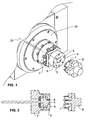
- the figure 1 illustrates the spindle (20) of a machine tool equipped with a workpiece holder (7) for carrying out the invention.
- the piece holder comprises two elements (3, 4) for mounting and positioning the blank (1). These two elements form a "divider", that is to say a set of two workpieces which will be, after the separation of the desired part from the rest of the blank, used to manipulate the two parts separately.
- the two elements (3 and 4) are round and coaxial with the axis (21) of rotation of the spindle (20), but they could also be of any shape, and non-coaxial with the axis of rotation, or even non-coaxial to each other.
- the shape and arrangement of the elements depend on the shape of the workpiece being machined and that of the wafer of which the desired workpiece is made.
- the figure 1 illustrates the course of the first step of a method according to the invention.
- the plate (1) which is provided with positioning holes, is provided by the gripper (8), is placed on the outer mounting element (3) of the workpiece carrier (7).
- This element (3) is provided with pins (5) for positioning which correspond to the holes of the wafer (1).
- the surface of the inner part of the divider (the element 4) is flush with that of the outer zone (the element 3).
- the inner element (4) is also provided with positioning pins (6), but these pins (6) are retractable, and during this first step, are retracted flush with or under the surface of the inner element ( 4).
- the figure 2 illustrates a section view of the representation of the figure 1 . From this figure we see a part of the mechanism for advancing or retracting the inner element (4) relative to the outer element (3). Although these figures show a carrier in which the inner portion (4) is retractable relative to the outer portion (3), it would be possible to reverse such that the outer member (3) is retracted relative to the inner member (4), or even to equip both with retraction means relative to each other, or to the workpiece holder (7).
- FIG 3 illustrates a second orthographic view of the representation of Figures 1 and 2 . From this figure, we see the holes (19) of positioning of the blank (1) ready to mount on the workpiece holder (7, 3, 4).
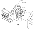
- the figure 4 shows the second step of the process.
- the blank is clamped on the workpiece holder (7) by a flange clamp (10) retractable in a plane substantially orthogonal to the axis (21) of rotation of the spindle (20).
- the side clamp (10) presses the part of the blank (1) which is not part of the desired part (here called the remaining part) - the outer part in this example - to hold the blank (1) in position during machining.
- the figure 4 also shows the machining of the part (called useful part here) of the blank (1) intended to become the desired part.
- the machining can include any kind of machining operations, such as grinding, milling, drilling or turning, for example, alone or in combination.
- a second set of holes (9) is machined in the useful part, which will help later to hold the useful part (2) in position on the workpiece carrier (7).
- the machining may also include partial cutting - a blank contouring to facilitate and simplify the subsequent cutting of the useful part (2) in the blank (1).
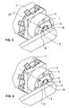
- the figure 5 illustrates the third step of the method - the flank (10) is retracted, and then a rotary retractable support (12) is set up to press the useful part (2) of the blank (1) against the workpiece holder (7, 4) to hold it in place during cutting.
- the figure 6 illustrates the fourth step of the process - the inner member (4) of the workpiece carrier (7) is advanced a little to press against the support (12), and the pins (6) of the inner element (4) come out and combine in the holes (9) machined in the second step.
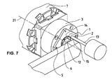
- the figure 7 illustrates the fifth step of the method, wherein the "bridges" (15) attaching the useful part (2) to the remaining part of the blank are removed by drilling, for example, or by other kinds of machining.
- the useful part (2) is now machined and detached from the rest of the blank (1).
- the useful part (2) is thus held at the workpiece holder (7), more precisely to the retractable inner member (4) of the workpiece carrier (7) by the support (12) and the pins (6) of the inner element (4).
- the Figures 8 to 10 illustrate the sixth step of the process - removing the remaining part (16) of the blank (1), and preparing the useful part (2) for finishing.
- the remaining part (16) is removed by the gripper (8) already used in the first step to put the blank (1) on the workpiece carrier (7). From these figures we also see the roughness and the remains of the "bridges" (15a) that will be removed in a finishing operation.
- the retractable element (4) of the workpiece carrier (7) is advanced, protruding from the outer element (3), to allow unhindered machining by the outer element (3) and its pins ( 6).
- Finishing being the eighth step of the process, is illustrated in the figure 11 .
- the useful part (2) of the blank is always held in place by the support (12) and the pins (6).
- the finishing is accomplished, by turning, with a finishing tool (17).
- the figure 12 illustrates the removal of the machined part (2) from the workpiece carrier (7, 4) by a suitable gripper (18), and the figure 13 watch how, after removal of the machined part (2), the retractable element (4) of the workpiece carrier (7), and its pins (6), are returned in preparation for the installation of the next workpiece to be machined .
- Step 1
- the inner pusher (4) is flush with the bearing zone (4), pins (6) retracted.
- the retractable flank (10) comes to hold the blank (1).
- the machined part (2) is not yet detached.
- the pusher (4) inside the divider (3, 4) advances one notch.
- the pins (6) come to hold the plate (2) but the pusher (4) is still not at the end of the race.
- the support (12) on the front face of the workpiece (2) is still in action.
- the axis (21) of the divider (3, 4) presents consecutively in front of the spindle (20) the two points (15) that remain to be machined to detach the part ( 2).
- the gripper (8) comes to find the contour of the tray (16) while the plate (2) remains on its pins.
- the inner pusher (4) comes to the end of stroke to clear the plate (2) farther than the pins (6) fixed on the divider (3, 4).
- the piece (2) is rotated (using the support 12 whose end is guided in rotation).
- the gripper 18 picks up the finished piece (2).
- the inner pusher (4) returns to the starting position, pins (6) retracted.
Landscapes
- Engineering & Computer Science (AREA)
- Mechanical Engineering (AREA)
- Physics & Mathematics (AREA)
- General Physics & Mathematics (AREA)
- Jigs For Machine Tools (AREA)
- Automatic Assembly (AREA)
- Lining Or Joining Of Plastics Or The Like (AREA)
- Milling, Drilling, And Turning Of Wood (AREA)
- Drilling And Boring (AREA)
Claims (10)
- Werkstückhalter (7) zum Halten eines Rohlings (1) in einer Position während einer maschinellen Bearbeitung in einer Werkzeugmaschine und unter der Steuerung einer Steuerungs-Software, um ein gewünschtes Stück (Werkstück) herzustellen,
wobei der Rohling (1) einen nutzbaren Teil aufweist, welcher maschinell bearbeitet und anschliessend ausgeschnitten werden soll, um das gewünschte Stück bereitzustellen, und einen verbleibenden Teil (16) aufweist, welcher nicht Teil des gewünschten Stücks sein soll,
wobei der Werkzeughalter Mittel (3, 4) zum Montieren und Positionieren des Rohlings (1) aufweist,
wobei der Werkzeughalter (7) aufweist:eines der Mittel zum Montieren und Positionieren, welches als erstes Element (4) bezeichnet wird und dazu ausgelegt ist, um den nutzbaren Teil (2) des Rohlings (1) in einer Position zu halten,ein weiteres der Mittel zum Montieren und Positionieren, welches als zweites Element (3) bezeichnet wird und dazu ausgelegt ist, um den verbleibenden Teil (16) des Rohlings (1) in einer Position zu halten, und wobei der Werkstückhalter dadurch gekennzeichnet ist, dass:mindestens eines der ersten und zweiten Elemente (3, 4) unter der Steuerung der Steuerungs-Software derart verschiebbar ist, dass ab dem Ausschneiden des Rohlings (1) das erste Element (4) bezüglich des zweiten Elements (3) vorgeschoben werden kann, um eine Fertigstellung des auf dem ersten Element (4) montierten nutzbaren Teils (2) zu erleichtern. - Werkstückhalter (7) nach Anspruch 1, bei welchem:das erste Element (4) erste Anordnungsmittel (6) aufweist, um mit zweiten umgekehrten Anordnungsmitteln (9) des nutzbaren Teils (2) des Rohlings (1) in Eingriff zu gelangen.
- Werkstückhalter (7) nach Anspruch 2, bei welchem:die ersten Anordnungsmittel (6) erste hervorstehende Stifte des ersten Elements (4) aufweisen.
- Werkstückhalter nach einem der Ansprüche 1 bis 3, bei welchem:die ersten Stifte einfahrbar sind zwischen einer ersten, sogenannten zurückgezogenen Position, bei welcher sie nicht über die erste Fläche hinausragen, und einer zweiten, sogenannten hervorstehenden Position, bei welcher sie von dem ersten Element (4) hervorstehen.
- Werkstückhalter nach einem der Ansprüche 1 bis 4, bei welchem die ersten Stifte Mittel zum Festklemmen des nutzbaren Teils (2) an dem ersten Element (4) des Werkstückhalters (7) aufweisen.
- Verfahren zum Herstellen eines gewünschten Stücks (Werkstück) von einem Rohling (1), wobei der Rohling einen nutzbaren Teil (2) aufweist, welcher der Teil des Rohlings ist, der maschinell bearbeitet und dann ausgeschnitten werden soll, um das gewünschte Stück bereitzustellen, und einen verbleibenden Teil (16) aufweist, welcher der Teil des Rohlings ist, der nicht Teil des gewünschten Stücks ist, wobei das Verfahren unter der Steuerung einer Steuerungs-Software in einer Werkzeugmaschine durchgeführt wird,
die Werkzeugmaschine einen Werkstückhalter (7) aufweist,
das Verfahren einen ersten Schritt zum Positionieren des Rohlings (1) auf dem Werkstückhalter (7) aufweist,
einen zweiten Schritt zum Festklemmen des Rohlings (1) in einer Position auf dem Werkstückhalter (7) aufweist,
einen dritten Schritt zum maschinellen Bearbeiten des nutzbaren Teils (2) des Rohlings (1) aufweist,
wobei das Festklemmen des zweiten Schritts ein Festklemmen des verbleibenden Teils (16) an dem zweiten Element (3) des Werkstückhalters (7) ist,
wobei der dritte Schritt ein derartiges partielles Ausschneiden des nutzbaren Teils aus dem Rohling (1) ist, dass der nutzbare Teil und der verbleibende Teil (16) nur über nicht ausgeschnittene Bereiche (15), sogenannte "Brücken", des Rohlings (1) befestigt sind,
wobei das Verfahren ausserdem aufweist:einen vierten Schritt zum Festklemmen des nutzbaren Teils an dem ersten Element (4),einen fünften Schritt zum Entfernen bzw. Beseitigen der "Brücken" und somit zur Trennung des nutzbaren Teils und des verbleibenden Teils,einen sechsten Schritt zum Entfernen des verbleibenden Teils (16) von dem Werkstückhalter (7),wobei das Verfahren dadurch gekennzeichnet ist, dass:der Werkstückhalter (7) ein erstes Element (4) aufweist, um den nutzbaren Teil des Rohlings (1) zu halten, und ein zweites Element (3) aufweist, um den verbleibenden Teil (16) des Rohlings (1) zu halten, wobei das erste und das zweite Element (4 und 3) entlang der Drehachse und unter der Steuerung der Steuerungs-Software in Bezug zueinander verschoben werden können,und dass das Verfahren einen siebten Schritt zum derartigen Verschieben des ersten Elements (4) des Werkstück-Halters (7) aufweist, dass der nutzbare Teil des Rohlings sich von dem zweiten Element (3) entfernt, undeinen achten Schritt zur maschinellen Nachbehandlung des nutzbaren Teils aufweist. - Herstellungsverfahren nach Anspruch 6, bei welchem das erste Element (4) und der nutzbare Teil (2) des Rohlings (1) komplementäre Anordnungsmittel (6, 9) aufweisen.
- Herstellungsverfahren nach Anspruch 7, bei welchem die komplementären Anordnungsmittel des ersten Elements (4) Positionierstifte aufweisen, welche verschiebbar sind zwischen einer in das erste Element (4) zurückgezogenen ersten Stellung und einer aus dem ersten Element (4) hervorstehenden zweiten Stellung,
und bei welchem die komplementären Anordnungsmittel des nutzbaren Teils (2) des Rohlings (1) Lochungen und/oder Aussparungen aufweisen, um eine genaue Positionierung des nutzbaren Teils auf dem ersten Element zu ermöglichen, wenn die Stifte von dem ersten Element hervorstehen. - Herstellungsverfahrung nach Anspruch 8, bei welchem der vierte Schritt eine derartige Verschiebung der Stifte zwischen der zurückgezogenen Stellung und der hervorstehenden Stellung aufweist, dass der nutzbare Teil von dem fünften bis zu dem achten Schritt in einer Position gehalten werden kann.
- Herstellungsverfahren nach Anspruch 6, bei welchem der achte Schritt eine maschinelle Bearbeitung der Kanten des ersten Teils aufweist, um jegliche Rauhigkeiten (15) zu beseitigen, die während des dritten und/oder fünften Schrittes erzeugt wurden.
Priority Applications (3)
| Application Number | Priority Date | Filing Date | Title |
|---|---|---|---|
| AT08020064T ATE513255T1 (de) | 2008-11-18 | 2008-11-18 | Bearbeitung von werkstücken mit einem einzigen klemmvorgang |
| ES08020064T ES2370933T3 (es) | 2008-11-18 | 2008-11-18 | Mecanizado de piezas con una sola operación de sujeción. |
| EP08020064A EP2187273B1 (de) | 2008-11-18 | 2008-11-18 | Bearbeitung von Werkstücken mit einem einzigen Klemmvorgang |
Applications Claiming Priority (1)
| Application Number | Priority Date | Filing Date | Title |
|---|---|---|---|
| EP08020064A EP2187273B1 (de) | 2008-11-18 | 2008-11-18 | Bearbeitung von Werkstücken mit einem einzigen Klemmvorgang |
Publications (2)
| Publication Number | Publication Date |
|---|---|
| EP2187273A1 EP2187273A1 (de) | 2010-05-19 |
| EP2187273B1 true EP2187273B1 (de) | 2011-06-15 |
Family
ID=40550199
Family Applications (1)
| Application Number | Title | Priority Date | Filing Date |
|---|---|---|---|
| EP08020064A Active EP2187273B1 (de) | 2008-11-18 | 2008-11-18 | Bearbeitung von Werkstücken mit einem einzigen Klemmvorgang |
Country Status (3)
| Country | Link |
|---|---|
| EP (1) | EP2187273B1 (de) |
| AT (1) | ATE513255T1 (de) |
| ES (1) | ES2370933T3 (de) |
Families Citing this family (2)
| Publication number | Priority date | Publication date | Assignee | Title |
|---|---|---|---|---|
| EP3639972B1 (de) * | 2018-10-17 | 2023-05-24 | ETA SA Manufacture Horlogère Suisse | Universalgreifer für scheiben von uhren |
| CN109634087B (zh) * | 2018-12-26 | 2020-08-25 | 厦门理工学院 | 一种钟表正极片旋转机构 |
Family Cites Families (4)
| Publication number | Priority date | Publication date | Assignee | Title |
|---|---|---|---|---|
| CH357942A (de) * | 1960-09-17 | 1961-10-31 | Hugo Allemann Ag | Halbautomatische Maschine für Bohr-, Gewindebohr- und Fräsarbeiten gegen die Mantelfläche eines plattenförmigen Arbeitsstückes |
| CH409584A (de) * | 1963-12-06 | 1966-03-15 | Hauser Ag Henri | Bearbeitungsmaschine und Verwendung derselben |
| KR920009967B1 (ko) * | 1990-11-01 | 1992-11-09 | 삼성전자 주식회사 | 선삭 가공물의 크램핑장치 |
| ATE430640T1 (de) * | 2006-11-03 | 2009-05-15 | Michel Yerly | Haltevorrichtung für werkstück |
-
2008
- 2008-11-18 EP EP08020064A patent/EP2187273B1/de active Active
- 2008-11-18 ES ES08020064T patent/ES2370933T3/es active Active
- 2008-11-18 AT AT08020064T patent/ATE513255T1/de active
Also Published As
| Publication number | Publication date |
|---|---|
| EP2187273A1 (de) | 2010-05-19 |
| ES2370933T3 (es) | 2011-12-23 |
| ATE513255T1 (de) | 2011-07-15 |
Similar Documents
| Publication | Publication Date | Title |
|---|---|---|
| US8672592B2 (en) | Milling collet having pull-out preventer for retaining a fluted milling tool | |
| EP2030727A1 (de) | Präzisionssteuervorrichtung in einer Bearbeitungsmaschine von zylindrischen Werkstücken | |
| EP2187273B1 (de) | Bearbeitung von Werkstücken mit einem einzigen Klemmvorgang | |
| EP1796871B9 (de) | Vorrichtung zum einspannen eines werkzeugeinsatzes in eine schleifmaschine | |
| EP1829638B1 (de) | Rotierendes Schneidwerkzeug mit zwei Schneidbereichen entgegengesetzter Schnittrichtung | |
| CH630277A5 (fr) | Dispositif de fixation, destine a maintenir une piece a travailler, pendant une operation d'usinage, sur une machine-outil. | |
| EP2500137B1 (de) | Schnellverschlussspindel | |
| EP1442833B1 (de) | Klemmvorrichtung und Verfahren zum Klemmen eines Teils mit solchen Klemmvorrichtungen | |
| EP2233247B1 (de) | Autonomes Hochleistungs-Bearbeitungszentrum mit vertikaler Teileentnahme | |
| FR2523884A1 (fr) | Outil d'usinage comportant un siege de plaque coupante et une plaque coupante amovibles | |
| FR2523010A1 (fr) | Procede de moletage coupant ou deformant, et des moyens de mise en oeuvre, destines a moleter ou rainurer des alesages ou portees cylindriques de pieces | |
| EP2801427B1 (de) | Schwingungsdämpfende Unterlage und Fräsverfahren eines Metallteils | |
| EP2688703B1 (de) | Verfahren und vorrichtung zur fräs- endbearbeitung | |
| EP0949030A1 (de) | Drehendes Schneidwerkzeug | |
| EP2382396B1 (de) | Verfahren zur positionierung von mechanischen teilen | |
| FR3070890B1 (fr) | Platine de travail a deux jeux d’outils sur une meme face | |
| FR3067956B1 (fr) | Dispositif d’adaptation d’un mors doux sur un mors dur | |
| FR2931382A1 (fr) | Dispositif de coupe pour machine de coupe,a avance manuelle ou mecanisee,de pieces a decouper et porte-outil pour un tel dispositif de coupe | |
| JP2009131915A (ja) | 切削工具および該切削工具を用いた切削方法 | |
| EP2943298B1 (de) | Positionierung von schneideklingen auf einem druckrahmen | |
| CH346182A (fr) | Procédé de décoration d'éléments de pièce d'horlogerie et appareil pour la mise en oeuvre de ce procédé | |
| FR3058080A1 (fr) | Element d’usinage tangentiel | |
| WO2026032870A1 (fr) | Dispositif de cintrage d'une pièce allongée | |
| CH721896A2 (fr) | Procédé de rabotage de cannelures d'une pièce d'horlogerie | |
| JP2004098249A (ja) | ピンミラーカッタ |
Legal Events
| Date | Code | Title | Description |
|---|---|---|---|
| PUAI | Public reference made under article 153(3) epc to a published international application that has entered the european phase |
Free format text: ORIGINAL CODE: 0009012 |
|
| AK | Designated contracting states |
Kind code of ref document: A1 Designated state(s): AT BE BG CH CY CZ DE DK EE ES FI FR GB GR HR HU IE IS IT LI LT LU LV MC MT NL NO PL PT RO SE SI SK TR |
|
| AX | Request for extension of the european patent |
Extension state: AL BA MK RS |
|
| 17P | Request for examination filed |
Effective date: 20101117 |
|
| GRAP | Despatch of communication of intention to grant a patent |
Free format text: ORIGINAL CODE: EPIDOSNIGR1 |
|
| AKX | Designation fees paid |
Designated state(s): AT BE BG CH CY CZ DE DK EE ES FI FR GB GR HR HU IE IS IT LI LT LU LV MC MT NL NO PL PT RO SE SI SK TR |
|
| GRAS | Grant fee paid |
Free format text: ORIGINAL CODE: EPIDOSNIGR3 |
|
| GRAA | (expected) grant |
Free format text: ORIGINAL CODE: 0009210 |
|
| AK | Designated contracting states |
Kind code of ref document: B1 Designated state(s): AT BE BG CH CY CZ DE DK EE ES FI FR GB GR HR HU IE IS IT LI LT LU LV MC MT NL NO PL PT RO SE SI SK TR |
|
| REG | Reference to a national code |
Ref country code: GB Ref legal event code: FG4D Free format text: NOT ENGLISH Ref country code: CH Ref legal event code: EP |
|
| REG | Reference to a national code |
Ref country code: IE Ref legal event code: FG4D Free format text: LANGUAGE OF EP DOCUMENT: FRENCH |
|
| REG | Reference to a national code |
Ref country code: DE Ref legal event code: R096 Ref document number: 602008007548 Country of ref document: DE Effective date: 20110804 |
|
| REG | Reference to a national code |
Ref country code: NL Ref legal event code: VDEP Effective date: 20110615 |
|
| REG | Reference to a national code |
Ref country code: CH Ref legal event code: NV Representative=s name: BOVARD AG |
|
| PG25 | Lapsed in a contracting state [announced via postgrant information from national office to epo] |
Ref country code: LT Free format text: LAPSE BECAUSE OF FAILURE TO SUBMIT A TRANSLATION OF THE DESCRIPTION OR TO PAY THE FEE WITHIN THE PRESCRIBED TIME-LIMIT Effective date: 20110615 Ref country code: HR Free format text: LAPSE BECAUSE OF FAILURE TO SUBMIT A TRANSLATION OF THE DESCRIPTION OR TO PAY THE FEE WITHIN THE PRESCRIBED TIME-LIMIT Effective date: 20110615 Ref country code: NO Free format text: LAPSE BECAUSE OF FAILURE TO SUBMIT A TRANSLATION OF THE DESCRIPTION OR TO PAY THE FEE WITHIN THE PRESCRIBED TIME-LIMIT Effective date: 20110915 Ref country code: SE Free format text: LAPSE BECAUSE OF FAILURE TO SUBMIT A TRANSLATION OF THE DESCRIPTION OR TO PAY THE FEE WITHIN THE PRESCRIBED TIME-LIMIT Effective date: 20110615 |
|
| PG25 | Lapsed in a contracting state [announced via postgrant information from national office to epo] |
Ref country code: CY Free format text: LAPSE BECAUSE OF FAILURE TO SUBMIT A TRANSLATION OF THE DESCRIPTION OR TO PAY THE FEE WITHIN THE PRESCRIBED TIME-LIMIT Effective date: 20110615 Ref country code: LV Free format text: LAPSE BECAUSE OF FAILURE TO SUBMIT A TRANSLATION OF THE DESCRIPTION OR TO PAY THE FEE WITHIN THE PRESCRIBED TIME-LIMIT Effective date: 20110615 Ref country code: SI Free format text: LAPSE BECAUSE OF FAILURE TO SUBMIT A TRANSLATION OF THE DESCRIPTION OR TO PAY THE FEE WITHIN THE PRESCRIBED TIME-LIMIT Effective date: 20110615 Ref country code: GR Free format text: LAPSE BECAUSE OF FAILURE TO SUBMIT A TRANSLATION OF THE DESCRIPTION OR TO PAY THE FEE WITHIN THE PRESCRIBED TIME-LIMIT Effective date: 20110916 Ref country code: FI Free format text: LAPSE BECAUSE OF FAILURE TO SUBMIT A TRANSLATION OF THE DESCRIPTION OR TO PAY THE FEE WITHIN THE PRESCRIBED TIME-LIMIT Effective date: 20110615 |
|
| REG | Reference to a national code |
Ref country code: ES Ref legal event code: FG2A Ref document number: 2370933 Country of ref document: ES Kind code of ref document: T3 Effective date: 20111223 |
|
| PG25 | Lapsed in a contracting state [announced via postgrant information from national office to epo] |
Ref country code: NL Free format text: LAPSE BECAUSE OF FAILURE TO SUBMIT A TRANSLATION OF THE DESCRIPTION OR TO PAY THE FEE WITHIN THE PRESCRIBED TIME-LIMIT Effective date: 20110615 |
|
| REG | Reference to a national code |
Ref country code: IE Ref legal event code: FD4D |
|
| PG25 | Lapsed in a contracting state [announced via postgrant information from national office to epo] |
Ref country code: IS Free format text: LAPSE BECAUSE OF FAILURE TO SUBMIT A TRANSLATION OF THE DESCRIPTION OR TO PAY THE FEE WITHIN THE PRESCRIBED TIME-LIMIT Effective date: 20111015 Ref country code: IE Free format text: LAPSE BECAUSE OF FAILURE TO SUBMIT A TRANSLATION OF THE DESCRIPTION OR TO PAY THE FEE WITHIN THE PRESCRIBED TIME-LIMIT Effective date: 20110615 Ref country code: PT Free format text: LAPSE BECAUSE OF FAILURE TO SUBMIT A TRANSLATION OF THE DESCRIPTION OR TO PAY THE FEE WITHIN THE PRESCRIBED TIME-LIMIT Effective date: 20111017 Ref country code: CZ Free format text: LAPSE BECAUSE OF FAILURE TO SUBMIT A TRANSLATION OF THE DESCRIPTION OR TO PAY THE FEE WITHIN THE PRESCRIBED TIME-LIMIT Effective date: 20110615 Ref country code: EE Free format text: LAPSE BECAUSE OF FAILURE TO SUBMIT A TRANSLATION OF THE DESCRIPTION OR TO PAY THE FEE WITHIN THE PRESCRIBED TIME-LIMIT Effective date: 20110615 |
|
| PG25 | Lapsed in a contracting state [announced via postgrant information from national office to epo] |
Ref country code: PL Free format text: LAPSE BECAUSE OF FAILURE TO SUBMIT A TRANSLATION OF THE DESCRIPTION OR TO PAY THE FEE WITHIN THE PRESCRIBED TIME-LIMIT Effective date: 20110615 Ref country code: SK Free format text: LAPSE BECAUSE OF FAILURE TO SUBMIT A TRANSLATION OF THE DESCRIPTION OR TO PAY THE FEE WITHIN THE PRESCRIBED TIME-LIMIT Effective date: 20110615 Ref country code: RO Free format text: LAPSE BECAUSE OF FAILURE TO SUBMIT A TRANSLATION OF THE DESCRIPTION OR TO PAY THE FEE WITHIN THE PRESCRIBED TIME-LIMIT Effective date: 20110615 |
|
| PLBE | No opposition filed within time limit |
Free format text: ORIGINAL CODE: 0009261 |
|
| STAA | Information on the status of an ep patent application or granted ep patent |
Free format text: STATUS: NO OPPOSITION FILED WITHIN TIME LIMIT |
|
| 26N | No opposition filed |
Effective date: 20120316 |
|
| BERE | Be: lapsed |
Owner name: ALMAC S.A. Effective date: 20111130 |
|
| PG25 | Lapsed in a contracting state [announced via postgrant information from national office to epo] |
Ref country code: DK Free format text: LAPSE BECAUSE OF FAILURE TO SUBMIT A TRANSLATION OF THE DESCRIPTION OR TO PAY THE FEE WITHIN THE PRESCRIBED TIME-LIMIT Effective date: 20110615 Ref country code: MC Free format text: LAPSE BECAUSE OF NON-PAYMENT OF DUE FEES Effective date: 20111130 |
|
| REG | Reference to a national code |
Ref country code: DE Ref legal event code: R097 Ref document number: 602008007548 Country of ref document: DE Effective date: 20120316 |
|
| REG | Reference to a national code |
Ref country code: FR Ref legal event code: ST Effective date: 20120731 |
|
| PG25 | Lapsed in a contracting state [announced via postgrant information from national office to epo] |
Ref country code: BE Free format text: LAPSE BECAUSE OF NON-PAYMENT OF DUE FEES Effective date: 20111130 |
|
| PG25 | Lapsed in a contracting state [announced via postgrant information from national office to epo] |
Ref country code: FR Free format text: LAPSE BECAUSE OF NON-PAYMENT OF DUE FEES Effective date: 20111130 |
|
| PG25 | Lapsed in a contracting state [announced via postgrant information from national office to epo] |
Ref country code: MT Free format text: LAPSE BECAUSE OF FAILURE TO SUBMIT A TRANSLATION OF THE DESCRIPTION OR TO PAY THE FEE WITHIN THE PRESCRIBED TIME-LIMIT Effective date: 20110615 |
|
| PGFP | Annual fee paid to national office [announced via postgrant information from national office to epo] |
Ref country code: ES Payment date: 20121127 Year of fee payment: 5 Ref country code: GB Payment date: 20121120 Year of fee payment: 5 |
|
| PG25 | Lapsed in a contracting state [announced via postgrant information from national office to epo] |
Ref country code: LU Free format text: LAPSE BECAUSE OF NON-PAYMENT OF DUE FEES Effective date: 20111118 |
|
| PG25 | Lapsed in a contracting state [announced via postgrant information from national office to epo] |
Ref country code: BG Free format text: LAPSE BECAUSE OF FAILURE TO SUBMIT A TRANSLATION OF THE DESCRIPTION OR TO PAY THE FEE WITHIN THE PRESCRIBED TIME-LIMIT Effective date: 20110915 |
|
| PG25 | Lapsed in a contracting state [announced via postgrant information from national office to epo] |
Ref country code: TR Free format text: LAPSE BECAUSE OF FAILURE TO SUBMIT A TRANSLATION OF THE DESCRIPTION OR TO PAY THE FEE WITHIN THE PRESCRIBED TIME-LIMIT Effective date: 20110615 |
|
| PG25 | Lapsed in a contracting state [announced via postgrant information from national office to epo] |
Ref country code: HU Free format text: LAPSE BECAUSE OF FAILURE TO SUBMIT A TRANSLATION OF THE DESCRIPTION OR TO PAY THE FEE WITHIN THE PRESCRIBED TIME-LIMIT Effective date: 20110615 |
|
| GBPC | Gb: european patent ceased through non-payment of renewal fee |
Effective date: 20131118 |
|
| PG25 | Lapsed in a contracting state [announced via postgrant information from national office to epo] |
Ref country code: GB Free format text: LAPSE BECAUSE OF NON-PAYMENT OF DUE FEES Effective date: 20131118 |
|
| REG | Reference to a national code |
Ref country code: AT Ref legal event code: MM01 Ref document number: 513255 Country of ref document: AT Kind code of ref document: T Effective date: 20131118 |
|
| PG25 | Lapsed in a contracting state [announced via postgrant information from national office to epo] |
Ref country code: AT Free format text: LAPSE BECAUSE OF NON-PAYMENT OF DUE FEES Effective date: 20131118 |
|
| REG | Reference to a national code |
Ref country code: ES Ref legal event code: FD2A Effective date: 20150327 |
|
| PG25 | Lapsed in a contracting state [announced via postgrant information from national office to epo] |
Ref country code: ES Free format text: LAPSE BECAUSE OF NON-PAYMENT OF DUE FEES Effective date: 20131119 |
|
| PGFP | Annual fee paid to national office [announced via postgrant information from national office to epo] |
Ref country code: IT Payment date: 20151124 Year of fee payment: 8 |
|
| PG25 | Lapsed in a contracting state [announced via postgrant information from national office to epo] |
Ref country code: IT Free format text: LAPSE BECAUSE OF NON-PAYMENT OF DUE FEES Effective date: 20161118 |
|
| PGFP | Annual fee paid to national office [announced via postgrant information from national office to epo] |
Ref country code: DE Payment date: 20191121 Year of fee payment: 12 |
|
| REG | Reference to a national code |
Ref country code: DE Ref legal event code: R119 Ref document number: 602008007548 Country of ref document: DE |
|
| PG25 | Lapsed in a contracting state [announced via postgrant information from national office to epo] |
Ref country code: DE Free format text: LAPSE BECAUSE OF NON-PAYMENT OF DUE FEES Effective date: 20210601 |
|
| REG | Reference to a national code |
Ref country code: CH Ref legal event code: U11 Free format text: ST27 STATUS EVENT CODE: U-0-0-U10-U11 (AS PROVIDED BY THE NATIONAL OFFICE) Effective date: 20251201 |
|
| PGFP | Annual fee paid to national office [announced via postgrant information from national office to epo] |
Ref country code: CH Payment date: 20251201 Year of fee payment: 18 |