EP2185877B1 - Procede et installation de liquefaction de gaz naturel - Google Patents
Procede et installation de liquefaction de gaz naturel Download PDFInfo
- Publication number
- EP2185877B1 EP2185877B1 EP08779824.5A EP08779824A EP2185877B1 EP 2185877 B1 EP2185877 B1 EP 2185877B1 EP 08779824 A EP08779824 A EP 08779824A EP 2185877 B1 EP2185877 B1 EP 2185877B1
- Authority
- EP
- European Patent Office
- Prior art keywords
- stream
- cooling
- kpa
- psia
- gas stream
- Prior art date
- Legal status (The legal status is an assumption and is not a legal conclusion. Google has not performed a legal analysis and makes no representation as to the accuracy of the status listed.)
- Active
Links
- 238000000034 method Methods 0.000 title claims description 43
- 230000008569 process Effects 0.000 title claims description 39
- VNWKTOKETHGBQD-UHFFFAOYSA-N methane Chemical compound C VNWKTOKETHGBQD-UHFFFAOYSA-N 0.000 title description 34
- 239000003345 natural gas Substances 0.000 title description 13
- 239000007789 gas Substances 0.000 claims description 130
- 238000001816 cooling Methods 0.000 claims description 105
- 239000003507 refrigerant Substances 0.000 claims description 87
- 230000006835 compression Effects 0.000 claims description 37
- 238000007906 compression Methods 0.000 claims description 37
- 239000003949 liquefied natural gas Substances 0.000 claims description 24
- 238000005057 refrigeration Methods 0.000 claims description 12
- 230000009467 reduction Effects 0.000 claims description 10
- 239000000446 fuel Substances 0.000 claims description 6
- 239000007788 liquid Substances 0.000 claims description 6
- 238000000926 separation method Methods 0.000 claims description 6
- 239000000112 cooling gas Substances 0.000 claims 7
- 239000012809 cooling fluid Substances 0.000 claims 4
- IJGRMHOSHXDMSA-UHFFFAOYSA-N Atomic nitrogen Chemical compound N#N IJGRMHOSHXDMSA-UHFFFAOYSA-N 0.000 description 21
- 229910052757 nitrogen Inorganic materials 0.000 description 10
- 239000012530 fluid Substances 0.000 description 9
- ATUOYWHBWRKTHZ-UHFFFAOYSA-N Propane Chemical compound CCC ATUOYWHBWRKTHZ-UHFFFAOYSA-N 0.000 description 6
- 230000008901 benefit Effects 0.000 description 5
- 239000000203 mixture Substances 0.000 description 5
- 238000004519 manufacturing process Methods 0.000 description 4
- XLYOFNOQVPJJNP-UHFFFAOYSA-N water Substances O XLYOFNOQVPJJNP-UHFFFAOYSA-N 0.000 description 4
- 241000196324 Embryophyta Species 0.000 description 3
- 239000003570 air Substances 0.000 description 3
- 239000001294 propane Substances 0.000 description 3
- 239000000126 substance Substances 0.000 description 3
- 230000000153 supplemental effect Effects 0.000 description 3
- CURLTUGMZLYLDI-UHFFFAOYSA-N Carbon dioxide Chemical compound O=C=O CURLTUGMZLYLDI-UHFFFAOYSA-N 0.000 description 2
- 241000183024 Populus tremula Species 0.000 description 2
- 239000002131 composite material Substances 0.000 description 2
- 239000002826 coolant Substances 0.000 description 2
- 230000007423 decrease Effects 0.000 description 2
- 238000010586 diagram Methods 0.000 description 2
- 230000000694 effects Effects 0.000 description 2
- 230000006872 improvement Effects 0.000 description 2
- 238000012986 modification Methods 0.000 description 2
- 230000004048 modification Effects 0.000 description 2
- 238000012545 processing Methods 0.000 description 2
- 239000013589 supplement Substances 0.000 description 2
- 239000004215 Carbon black (E152) Substances 0.000 description 1
- OTMSDBZUPAUEDD-UHFFFAOYSA-N Ethane Chemical compound CC OTMSDBZUPAUEDD-UHFFFAOYSA-N 0.000 description 1
- VGGSQFUCUMXWEO-UHFFFAOYSA-N Ethene Chemical compound C=C VGGSQFUCUMXWEO-UHFFFAOYSA-N 0.000 description 1
- 239000005977 Ethylene Substances 0.000 description 1
- 239000012080 ambient air Substances 0.000 description 1
- 230000015572 biosynthetic process Effects 0.000 description 1
- 239000001273 butane Substances 0.000 description 1
- 229910002092 carbon dioxide Inorganic materials 0.000 description 1
- 239000001569 carbon dioxide Substances 0.000 description 1
- 238000006243 chemical reaction Methods 0.000 description 1
- 239000000356 contaminant Substances 0.000 description 1
- 230000008878 coupling Effects 0.000 description 1
- 238000010168 coupling process Methods 0.000 description 1
- 238000005859 coupling reaction Methods 0.000 description 1
- 230000001419 dependent effect Effects 0.000 description 1
- 238000013461 design Methods 0.000 description 1
- 229910001873 dinitrogen Inorganic materials 0.000 description 1
- 238000006073 displacement reaction Methods 0.000 description 1
- 238000004821 distillation Methods 0.000 description 1
- 230000009977 dual effect Effects 0.000 description 1
- 230000003028 elevating effect Effects 0.000 description 1
- 238000005516 engineering process Methods 0.000 description 1
- 229930195733 hydrocarbon Natural products 0.000 description 1
- 150000002430 hydrocarbons Chemical class 0.000 description 1
- IJDNQMDRQITEOD-UHFFFAOYSA-N n-butane Chemical compound CCCC IJDNQMDRQITEOD-UHFFFAOYSA-N 0.000 description 1
- OFBQJSOFQDEBGM-UHFFFAOYSA-N n-pentane Natural products CCCCC OFBQJSOFQDEBGM-UHFFFAOYSA-N 0.000 description 1
- QJGQUHMNIGDVPM-UHFFFAOYSA-N nitrogen group Chemical group [N] QJGQUHMNIGDVPM-UHFFFAOYSA-N 0.000 description 1
- 238000010248 power generation Methods 0.000 description 1
- 238000012546 transfer Methods 0.000 description 1
- 238000010792 warming Methods 0.000 description 1
Images


Classifications
-
- F—MECHANICAL ENGINEERING; LIGHTING; HEATING; WEAPONS; BLASTING
- F25—REFRIGERATION OR COOLING; COMBINED HEATING AND REFRIGERATION SYSTEMS; HEAT PUMP SYSTEMS; MANUFACTURE OR STORAGE OF ICE; LIQUEFACTION SOLIDIFICATION OF GASES
- F25J—LIQUEFACTION, SOLIDIFICATION OR SEPARATION OF GASES OR GASEOUS OR LIQUEFIED GASEOUS MIXTURES BY PRESSURE AND COLD TREATMENT OR BY BRINGING THEM INTO THE SUPERCRITICAL STATE
- F25J1/00—Processes or apparatus for liquefying or solidifying gases or gaseous mixtures
- F25J1/0002—Processes or apparatus for liquefying or solidifying gases or gaseous mixtures characterised by the fluid to be liquefied
- F25J1/0022—Hydrocarbons, e.g. natural gas
-
- F—MECHANICAL ENGINEERING; LIGHTING; HEATING; WEAPONS; BLASTING
- F25—REFRIGERATION OR COOLING; COMBINED HEATING AND REFRIGERATION SYSTEMS; HEAT PUMP SYSTEMS; MANUFACTURE OR STORAGE OF ICE; LIQUEFACTION SOLIDIFICATION OF GASES
- F25J—LIQUEFACTION, SOLIDIFICATION OR SEPARATION OF GASES OR GASEOUS OR LIQUEFIED GASEOUS MIXTURES BY PRESSURE AND COLD TREATMENT OR BY BRINGING THEM INTO THE SUPERCRITICAL STATE
- F25J1/00—Processes or apparatus for liquefying or solidifying gases or gaseous mixtures
- F25J1/003—Processes or apparatus for liquefying or solidifying gases or gaseous mixtures characterised by the kind of cold generation within the liquefaction unit for compensating heat leaks and liquid production
- F25J1/0032—Processes or apparatus for liquefying or solidifying gases or gaseous mixtures characterised by the kind of cold generation within the liquefaction unit for compensating heat leaks and liquid production using the feed stream itself or separated fractions from it, i.e. "internal refrigeration"
- F25J1/0035—Processes or apparatus for liquefying or solidifying gases or gaseous mixtures characterised by the kind of cold generation within the liquefaction unit for compensating heat leaks and liquid production using the feed stream itself or separated fractions from it, i.e. "internal refrigeration" by gas expansion with extraction of work
- F25J1/0037—Processes or apparatus for liquefying or solidifying gases or gaseous mixtures characterised by the kind of cold generation within the liquefaction unit for compensating heat leaks and liquid production using the feed stream itself or separated fractions from it, i.e. "internal refrigeration" by gas expansion with extraction of work of a return stream
-
- F—MECHANICAL ENGINEERING; LIGHTING; HEATING; WEAPONS; BLASTING
- F25—REFRIGERATION OR COOLING; COMBINED HEATING AND REFRIGERATION SYSTEMS; HEAT PUMP SYSTEMS; MANUFACTURE OR STORAGE OF ICE; LIQUEFACTION SOLIDIFICATION OF GASES
- F25J—LIQUEFACTION, SOLIDIFICATION OR SEPARATION OF GASES OR GASEOUS OR LIQUEFIED GASEOUS MIXTURES BY PRESSURE AND COLD TREATMENT OR BY BRINGING THEM INTO THE SUPERCRITICAL STATE
- F25J1/00—Processes or apparatus for liquefying or solidifying gases or gaseous mixtures
- F25J1/003—Processes or apparatus for liquefying or solidifying gases or gaseous mixtures characterised by the kind of cold generation within the liquefaction unit for compensating heat leaks and liquid production
- F25J1/0032—Processes or apparatus for liquefying or solidifying gases or gaseous mixtures characterised by the kind of cold generation within the liquefaction unit for compensating heat leaks and liquid production using the feed stream itself or separated fractions from it, i.e. "internal refrigeration"
- F25J1/004—Processes or apparatus for liquefying or solidifying gases or gaseous mixtures characterised by the kind of cold generation within the liquefaction unit for compensating heat leaks and liquid production using the feed stream itself or separated fractions from it, i.e. "internal refrigeration" by flash gas recovery
-
- F—MECHANICAL ENGINEERING; LIGHTING; HEATING; WEAPONS; BLASTING
- F25—REFRIGERATION OR COOLING; COMBINED HEATING AND REFRIGERATION SYSTEMS; HEAT PUMP SYSTEMS; MANUFACTURE OR STORAGE OF ICE; LIQUEFACTION SOLIDIFICATION OF GASES
- F25J—LIQUEFACTION, SOLIDIFICATION OR SEPARATION OF GASES OR GASEOUS OR LIQUEFIED GASEOUS MIXTURES BY PRESSURE AND COLD TREATMENT OR BY BRINGING THEM INTO THE SUPERCRITICAL STATE
- F25J1/00—Processes or apparatus for liquefying or solidifying gases or gaseous mixtures
- F25J1/003—Processes or apparatus for liquefying or solidifying gases or gaseous mixtures characterised by the kind of cold generation within the liquefaction unit for compensating heat leaks and liquid production
- F25J1/0032—Processes or apparatus for liquefying or solidifying gases or gaseous mixtures characterised by the kind of cold generation within the liquefaction unit for compensating heat leaks and liquid production using the feed stream itself or separated fractions from it, i.e. "internal refrigeration"
- F25J1/0042—Processes or apparatus for liquefying or solidifying gases or gaseous mixtures characterised by the kind of cold generation within the liquefaction unit for compensating heat leaks and liquid production using the feed stream itself or separated fractions from it, i.e. "internal refrigeration" by liquid expansion with extraction of work
-
- F—MECHANICAL ENGINEERING; LIGHTING; HEATING; WEAPONS; BLASTING
- F25—REFRIGERATION OR COOLING; COMBINED HEATING AND REFRIGERATION SYSTEMS; HEAT PUMP SYSTEMS; MANUFACTURE OR STORAGE OF ICE; LIQUEFACTION SOLIDIFICATION OF GASES
- F25J—LIQUEFACTION, SOLIDIFICATION OR SEPARATION OF GASES OR GASEOUS OR LIQUEFIED GASEOUS MIXTURES BY PRESSURE AND COLD TREATMENT OR BY BRINGING THEM INTO THE SUPERCRITICAL STATE
- F25J1/00—Processes or apparatus for liquefying or solidifying gases or gaseous mixtures
- F25J1/003—Processes or apparatus for liquefying or solidifying gases or gaseous mixtures characterised by the kind of cold generation within the liquefaction unit for compensating heat leaks and liquid production
- F25J1/0032—Processes or apparatus for liquefying or solidifying gases or gaseous mixtures characterised by the kind of cold generation within the liquefaction unit for compensating heat leaks and liquid production using the feed stream itself or separated fractions from it, i.e. "internal refrigeration"
- F25J1/0045—Processes or apparatus for liquefying or solidifying gases or gaseous mixtures characterised by the kind of cold generation within the liquefaction unit for compensating heat leaks and liquid production using the feed stream itself or separated fractions from it, i.e. "internal refrigeration" by vaporising a liquid return stream
-
- F—MECHANICAL ENGINEERING; LIGHTING; HEATING; WEAPONS; BLASTING
- F25—REFRIGERATION OR COOLING; COMBINED HEATING AND REFRIGERATION SYSTEMS; HEAT PUMP SYSTEMS; MANUFACTURE OR STORAGE OF ICE; LIQUEFACTION SOLIDIFICATION OF GASES
- F25J—LIQUEFACTION, SOLIDIFICATION OR SEPARATION OF GASES OR GASEOUS OR LIQUEFIED GASEOUS MIXTURES BY PRESSURE AND COLD TREATMENT OR BY BRINGING THEM INTO THE SUPERCRITICAL STATE
- F25J1/00—Processes or apparatus for liquefying or solidifying gases or gaseous mixtures
- F25J1/003—Processes or apparatus for liquefying or solidifying gases or gaseous mixtures characterised by the kind of cold generation within the liquefaction unit for compensating heat leaks and liquid production
- F25J1/0047—Processes or apparatus for liquefying or solidifying gases or gaseous mixtures characterised by the kind of cold generation within the liquefaction unit for compensating heat leaks and liquid production using an "external" refrigerant stream in a closed vapor compression cycle
- F25J1/005—Processes or apparatus for liquefying or solidifying gases or gaseous mixtures characterised by the kind of cold generation within the liquefaction unit for compensating heat leaks and liquid production using an "external" refrigerant stream in a closed vapor compression cycle by expansion of a gaseous refrigerant stream with extraction of work
-
- F—MECHANICAL ENGINEERING; LIGHTING; HEATING; WEAPONS; BLASTING
- F25—REFRIGERATION OR COOLING; COMBINED HEATING AND REFRIGERATION SYSTEMS; HEAT PUMP SYSTEMS; MANUFACTURE OR STORAGE OF ICE; LIQUEFACTION SOLIDIFICATION OF GASES
- F25J—LIQUEFACTION, SOLIDIFICATION OR SEPARATION OF GASES OR GASEOUS OR LIQUEFIED GASEOUS MIXTURES BY PRESSURE AND COLD TREATMENT OR BY BRINGING THEM INTO THE SUPERCRITICAL STATE
- F25J1/00—Processes or apparatus for liquefying or solidifying gases or gaseous mixtures
- F25J1/006—Processes or apparatus for liquefying or solidifying gases or gaseous mixtures characterised by the refrigerant fluid used
- F25J1/007—Primary atmospheric gases, mixtures thereof
- F25J1/0072—Nitrogen
-
- F—MECHANICAL ENGINEERING; LIGHTING; HEATING; WEAPONS; BLASTING
- F25—REFRIGERATION OR COOLING; COMBINED HEATING AND REFRIGERATION SYSTEMS; HEAT PUMP SYSTEMS; MANUFACTURE OR STORAGE OF ICE; LIQUEFACTION SOLIDIFICATION OF GASES
- F25J—LIQUEFACTION, SOLIDIFICATION OR SEPARATION OF GASES OR GASEOUS OR LIQUEFIED GASEOUS MIXTURES BY PRESSURE AND COLD TREATMENT OR BY BRINGING THEM INTO THE SUPERCRITICAL STATE
- F25J1/00—Processes or apparatus for liquefying or solidifying gases or gaseous mixtures
- F25J1/006—Processes or apparatus for liquefying or solidifying gases or gaseous mixtures characterised by the refrigerant fluid used
- F25J1/008—Hydrocarbons
- F25J1/0082—Methane
-
- F—MECHANICAL ENGINEERING; LIGHTING; HEATING; WEAPONS; BLASTING
- F25—REFRIGERATION OR COOLING; COMBINED HEATING AND REFRIGERATION SYSTEMS; HEAT PUMP SYSTEMS; MANUFACTURE OR STORAGE OF ICE; LIQUEFACTION SOLIDIFICATION OF GASES
- F25J—LIQUEFACTION, SOLIDIFICATION OR SEPARATION OF GASES OR GASEOUS OR LIQUEFIED GASEOUS MIXTURES BY PRESSURE AND COLD TREATMENT OR BY BRINGING THEM INTO THE SUPERCRITICAL STATE
- F25J1/00—Processes or apparatus for liquefying or solidifying gases or gaseous mixtures
- F25J1/006—Processes or apparatus for liquefying or solidifying gases or gaseous mixtures characterised by the refrigerant fluid used
- F25J1/008—Hydrocarbons
- F25J1/0092—Mixtures of hydrocarbons comprising possibly also minor amounts of nitrogen
-
- F—MECHANICAL ENGINEERING; LIGHTING; HEATING; WEAPONS; BLASTING
- F25—REFRIGERATION OR COOLING; COMBINED HEATING AND REFRIGERATION SYSTEMS; HEAT PUMP SYSTEMS; MANUFACTURE OR STORAGE OF ICE; LIQUEFACTION SOLIDIFICATION OF GASES
- F25J—LIQUEFACTION, SOLIDIFICATION OR SEPARATION OF GASES OR GASEOUS OR LIQUEFIED GASEOUS MIXTURES BY PRESSURE AND COLD TREATMENT OR BY BRINGING THEM INTO THE SUPERCRITICAL STATE
- F25J1/00—Processes or apparatus for liquefying or solidifying gases or gaseous mixtures
- F25J1/02—Processes or apparatus for liquefying or solidifying gases or gaseous mixtures requiring the use of refrigeration, e.g. of helium or hydrogen ; Details and kind of the refrigeration system used; Integration with other units or processes; Controlling aspects of the process
- F25J1/0211—Processes or apparatus for liquefying or solidifying gases or gaseous mixtures requiring the use of refrigeration, e.g. of helium or hydrogen ; Details and kind of the refrigeration system used; Integration with other units or processes; Controlling aspects of the process using a multi-component refrigerant [MCR] fluid in a closed vapor compression cycle
- F25J1/0214—Processes or apparatus for liquefying or solidifying gases or gaseous mixtures requiring the use of refrigeration, e.g. of helium or hydrogen ; Details and kind of the refrigeration system used; Integration with other units or processes; Controlling aspects of the process using a multi-component refrigerant [MCR] fluid in a closed vapor compression cycle as a dual level refrigeration cascade with at least one MCR cycle
- F25J1/0215—Processes or apparatus for liquefying or solidifying gases or gaseous mixtures requiring the use of refrigeration, e.g. of helium or hydrogen ; Details and kind of the refrigeration system used; Integration with other units or processes; Controlling aspects of the process using a multi-component refrigerant [MCR] fluid in a closed vapor compression cycle as a dual level refrigeration cascade with at least one MCR cycle with one SCR cycle
-
- F—MECHANICAL ENGINEERING; LIGHTING; HEATING; WEAPONS; BLASTING
- F25—REFRIGERATION OR COOLING; COMBINED HEATING AND REFRIGERATION SYSTEMS; HEAT PUMP SYSTEMS; MANUFACTURE OR STORAGE OF ICE; LIQUEFACTION SOLIDIFICATION OF GASES
- F25J—LIQUEFACTION, SOLIDIFICATION OR SEPARATION OF GASES OR GASEOUS OR LIQUEFIED GASEOUS MIXTURES BY PRESSURE AND COLD TREATMENT OR BY BRINGING THEM INTO THE SUPERCRITICAL STATE
- F25J1/00—Processes or apparatus for liquefying or solidifying gases or gaseous mixtures
- F25J1/02—Processes or apparatus for liquefying or solidifying gases or gaseous mixtures requiring the use of refrigeration, e.g. of helium or hydrogen ; Details and kind of the refrigeration system used; Integration with other units or processes; Controlling aspects of the process
- F25J1/0211—Processes or apparatus for liquefying or solidifying gases or gaseous mixtures requiring the use of refrigeration, e.g. of helium or hydrogen ; Details and kind of the refrigeration system used; Integration with other units or processes; Controlling aspects of the process using a multi-component refrigerant [MCR] fluid in a closed vapor compression cycle
- F25J1/0219—Processes or apparatus for liquefying or solidifying gases or gaseous mixtures requiring the use of refrigeration, e.g. of helium or hydrogen ; Details and kind of the refrigeration system used; Integration with other units or processes; Controlling aspects of the process using a multi-component refrigerant [MCR] fluid in a closed vapor compression cycle in combination with an internal quasi-closed refrigeration loop, e.g. using a deep flash recycle loop
-
- F—MECHANICAL ENGINEERING; LIGHTING; HEATING; WEAPONS; BLASTING
- F25—REFRIGERATION OR COOLING; COMBINED HEATING AND REFRIGERATION SYSTEMS; HEAT PUMP SYSTEMS; MANUFACTURE OR STORAGE OF ICE; LIQUEFACTION SOLIDIFICATION OF GASES
- F25J—LIQUEFACTION, SOLIDIFICATION OR SEPARATION OF GASES OR GASEOUS OR LIQUEFIED GASEOUS MIXTURES BY PRESSURE AND COLD TREATMENT OR BY BRINGING THEM INTO THE SUPERCRITICAL STATE
- F25J1/00—Processes or apparatus for liquefying or solidifying gases or gaseous mixtures
- F25J1/02—Processes or apparatus for liquefying or solidifying gases or gaseous mixtures requiring the use of refrigeration, e.g. of helium or hydrogen ; Details and kind of the refrigeration system used; Integration with other units or processes; Controlling aspects of the process
- F25J1/0243—Start-up or control of the process; Details of the apparatus used; Details of the refrigerant compression system used
- F25J1/0244—Operation; Control and regulation; Instrumentation
- F25J1/0245—Different modes, i.e. 'runs', of operation; Process control
- F25J1/0249—Controlling refrigerant inventory, i.e. composition or quantity
- F25J1/025—Details related to the refrigerant production or treatment, e.g. make-up supply from feed gas itself
-
- F—MECHANICAL ENGINEERING; LIGHTING; HEATING; WEAPONS; BLASTING
- F25—REFRIGERATION OR COOLING; COMBINED HEATING AND REFRIGERATION SYSTEMS; HEAT PUMP SYSTEMS; MANUFACTURE OR STORAGE OF ICE; LIQUEFACTION SOLIDIFICATION OF GASES
- F25J—LIQUEFACTION, SOLIDIFICATION OR SEPARATION OF GASES OR GASEOUS OR LIQUEFIED GASEOUS MIXTURES BY PRESSURE AND COLD TREATMENT OR BY BRINGING THEM INTO THE SUPERCRITICAL STATE
- F25J1/00—Processes or apparatus for liquefying or solidifying gases or gaseous mixtures
- F25J1/02—Processes or apparatus for liquefying or solidifying gases or gaseous mixtures requiring the use of refrigeration, e.g. of helium or hydrogen ; Details and kind of the refrigeration system used; Integration with other units or processes; Controlling aspects of the process
- F25J1/0243—Start-up or control of the process; Details of the apparatus used; Details of the refrigerant compression system used
- F25J1/0244—Operation; Control and regulation; Instrumentation
- F25J1/0254—Operation; Control and regulation; Instrumentation controlling particular process parameter, e.g. pressure, temperature
-
- F—MECHANICAL ENGINEERING; LIGHTING; HEATING; WEAPONS; BLASTING
- F25—REFRIGERATION OR COOLING; COMBINED HEATING AND REFRIGERATION SYSTEMS; HEAT PUMP SYSTEMS; MANUFACTURE OR STORAGE OF ICE; LIQUEFACTION SOLIDIFICATION OF GASES
- F25J—LIQUEFACTION, SOLIDIFICATION OR SEPARATION OF GASES OR GASEOUS OR LIQUEFIED GASEOUS MIXTURES BY PRESSURE AND COLD TREATMENT OR BY BRINGING THEM INTO THE SUPERCRITICAL STATE
- F25J1/00—Processes or apparatus for liquefying or solidifying gases or gaseous mixtures
- F25J1/02—Processes or apparatus for liquefying or solidifying gases or gaseous mixtures requiring the use of refrigeration, e.g. of helium or hydrogen ; Details and kind of the refrigeration system used; Integration with other units or processes; Controlling aspects of the process
- F25J1/0243—Start-up or control of the process; Details of the apparatus used; Details of the refrigerant compression system used
- F25J1/0279—Compression of refrigerant or internal recycle fluid, e.g. kind of compressor, accumulator, suction drum etc.
- F25J1/0285—Combination of different types of drivers mechanically coupled to the same refrigerant compressor, possibly split on multiple compressor casings
- F25J1/0288—Combination of different types of drivers mechanically coupled to the same refrigerant compressor, possibly split on multiple compressor casings using work extraction by mechanical coupling of compression and expansion of the refrigerant, so-called companders
-
- F—MECHANICAL ENGINEERING; LIGHTING; HEATING; WEAPONS; BLASTING
- F25—REFRIGERATION OR COOLING; COMBINED HEATING AND REFRIGERATION SYSTEMS; HEAT PUMP SYSTEMS; MANUFACTURE OR STORAGE OF ICE; LIQUEFACTION SOLIDIFICATION OF GASES
- F25J—LIQUEFACTION, SOLIDIFICATION OR SEPARATION OF GASES OR GASEOUS OR LIQUEFIED GASEOUS MIXTURES BY PRESSURE AND COLD TREATMENT OR BY BRINGING THEM INTO THE SUPERCRITICAL STATE
- F25J2210/00—Processes characterised by the type or other details of the feed stream
- F25J2210/06—Splitting of the feed stream, e.g. for treating or cooling in different ways
-
- F—MECHANICAL ENGINEERING; LIGHTING; HEATING; WEAPONS; BLASTING
- F25—REFRIGERATION OR COOLING; COMBINED HEATING AND REFRIGERATION SYSTEMS; HEAT PUMP SYSTEMS; MANUFACTURE OR STORAGE OF ICE; LIQUEFACTION SOLIDIFICATION OF GASES
- F25J—LIQUEFACTION, SOLIDIFICATION OR SEPARATION OF GASES OR GASEOUS OR LIQUEFIED GASEOUS MIXTURES BY PRESSURE AND COLD TREATMENT OR BY BRINGING THEM INTO THE SUPERCRITICAL STATE
- F25J2220/00—Processes or apparatus involving steps for the removal of impurities
- F25J2220/60—Separating impurities from natural gas, e.g. mercury, cyclic hydrocarbons
- F25J2220/62—Separating low boiling components, e.g. He, H2, N2, Air
-
- F—MECHANICAL ENGINEERING; LIGHTING; HEATING; WEAPONS; BLASTING
- F25—REFRIGERATION OR COOLING; COMBINED HEATING AND REFRIGERATION SYSTEMS; HEAT PUMP SYSTEMS; MANUFACTURE OR STORAGE OF ICE; LIQUEFACTION SOLIDIFICATION OF GASES
- F25J—LIQUEFACTION, SOLIDIFICATION OR SEPARATION OF GASES OR GASEOUS OR LIQUEFIED GASEOUS MIXTURES BY PRESSURE AND COLD TREATMENT OR BY BRINGING THEM INTO THE SUPERCRITICAL STATE
- F25J2230/00—Processes or apparatus involving steps for increasing the pressure of gaseous process streams
- F25J2230/30—Compression of the feed stream
-
- F—MECHANICAL ENGINEERING; LIGHTING; HEATING; WEAPONS; BLASTING
- F25—REFRIGERATION OR COOLING; COMBINED HEATING AND REFRIGERATION SYSTEMS; HEAT PUMP SYSTEMS; MANUFACTURE OR STORAGE OF ICE; LIQUEFACTION SOLIDIFICATION OF GASES
- F25J—LIQUEFACTION, SOLIDIFICATION OR SEPARATION OF GASES OR GASEOUS OR LIQUEFIED GASEOUS MIXTURES BY PRESSURE AND COLD TREATMENT OR BY BRINGING THEM INTO THE SUPERCRITICAL STATE
- F25J2270/00—Refrigeration techniques used
- F25J2270/02—Internal refrigeration with liquid vaporising loop
-
- F—MECHANICAL ENGINEERING; LIGHTING; HEATING; WEAPONS; BLASTING
- F25—REFRIGERATION OR COOLING; COMBINED HEATING AND REFRIGERATION SYSTEMS; HEAT PUMP SYSTEMS; MANUFACTURE OR STORAGE OF ICE; LIQUEFACTION SOLIDIFICATION OF GASES
- F25J—LIQUEFACTION, SOLIDIFICATION OR SEPARATION OF GASES OR GASEOUS OR LIQUEFIED GASEOUS MIXTURES BY PRESSURE AND COLD TREATMENT OR BY BRINGING THEM INTO THE SUPERCRITICAL STATE
- F25J2270/00—Refrigeration techniques used
- F25J2270/04—Internal refrigeration with work-producing gas expansion loop
-
- F—MECHANICAL ENGINEERING; LIGHTING; HEATING; WEAPONS; BLASTING
- F25—REFRIGERATION OR COOLING; COMBINED HEATING AND REFRIGERATION SYSTEMS; HEAT PUMP SYSTEMS; MANUFACTURE OR STORAGE OF ICE; LIQUEFACTION SOLIDIFICATION OF GASES
- F25J—LIQUEFACTION, SOLIDIFICATION OR SEPARATION OF GASES OR GASEOUS OR LIQUEFIED GASEOUS MIXTURES BY PRESSURE AND COLD TREATMENT OR BY BRINGING THEM INTO THE SUPERCRITICAL STATE
- F25J2270/00—Refrigeration techniques used
- F25J2270/08—Internal refrigeration by flash gas recovery loop
Definitions
- Embodiments of the invention relate generally to the liquefaction of gases, and more specifically liquefaction of natural gas, particularly the liquefaction of gases in remote locations.
- LNG liquefied natural gas
- the refrigerants used may be a mixture of components such as methane, ethane, propane, butane, and nitrogen in multi-component refrigeration cycles.
- the refrigerants may also be pure substances such as propane, ethylene, or nitrogen in "cascade cycles.” Substantial volumes of these refrigerants with close control of composition are required. Further, such refrigerants may have to be imported and stored imposing logistics requirements.
- some of the components of the refrigerant may be prepared, typically by a distillation process integrated with the liquefaction process.
- gas expanders to provide the feed gas cooling thereby eliminating or reducing the logistical problems of refrigerant handling has been of interest to process engineers.
- the expander system operates on the principle that the feed gas can be allowed to expand through an expansion turbine, thereby performing work and reducing the temperature of the gas.
- the low temperature gas is then heat exchanged with the feed gas to provide the refrigeration needed.
- Supplemental cooling is typically needed to fully liquefy the feed gas and this may be provided by additional refrigerant systems, such as secondary cooling loops.
- the power obtained from cooling expansions in gas expanders can be used to supply part of the main compression power used in the refrigeration cycle.
- WO 2007/021351 a portion of the feed gas stream after feed gas compression is withdrawn to provide the refrigerant for the primary expander loop, instead of withdrawing said portion before said feed gas compression, and, in that the feed gas stream is compressed to a considerably lower pressure than in the inventive process and system, as well as in that less details with respect to the realization of the sub-cooling expander cycle using a portion of the expanded, cooled feed gas stream are provided in WO 2007/021351 which, therein is also realized with an expansion turbine instead of a reduction valve. It has also been discovered that adding external cooling to such a primary cooling loop provides additional advantages in many situations. See PCT/US08/02861 .
- expander cycles result in a high recycle gas stream flow rate and resulting high cooling load, introducing inefficiencies for the primary cooling (warm) stage, gas expander processes such as described above further cool the feed gas after it has been pre-cooled using a refrigerant in a secondary cooling unit.
- gas expander processes such as described above further cool the feed gas after it has been pre-cooled using a refrigerant in a secondary cooling unit.
- US Patent 6,412,302 and US Patent 5,916,260 present expander cycles which describe the use of nitrogen as refrigerant in the sub-cooling loop.
- the primary (warm-end) expander cooling loop operates at low pressure and therefore limits the fraction of the feed gas cooling load provided by this primary loop. Consequently, a nitrogen (or nitrogen-rich) refrigerant is required in the subcooling loop.
- WO 2007/021351 uses a portion of the flash gas derived from the feed gas in the final separation unit.
- an element in expander cycle processes is the requirement for at least one second refrigeration cycle to sub-cool the feed gas before it enters the final expander for conversion of much, if not all, remaining gaseous feed to LNG.
- Pillarella et al. "The C3MR Liquefaction Cycle: Versatility for a Fast Growing, Ever Changing LNG Industry", International Conference and Exhibition on Liquefied Natural Gas, XX, XX, vol. 15th, 24 May 2007, pgs. PS2-5.1 to PS2-5.13, XP009108435 discusses the versatility of the propane pre-cooled mixed refrigerant (C3MR) process and its ability to meet the demands of a broader range of process requirements in new LNG plants. Jones et al., “The Effect of Pressure on Liquefaction Processes", International Conference and Exhibition on Liquefied Natural Gas, XX. XX, no. 11 conf., 6 July 1995, poster A-5, pgs.
- C3MR propane pre-cooled mixed refrigerant
- U.S. Patent 7,219,512 is directed to a method of producing LNG on a small scale using unpurified natural gas feed and including a water clean-up cycle and a carbon dioxide clean-up cycle.
- the invention is a process for liquefying a gas stream, particularly one rich in methane, according to independent claim 1. Preferred embodiments of the inventive process are presented in the dependent claims.
- a system for treating a gaseous feed stream according to the invention is defined by independent claim 7.
- Embodiments of the present invention provide increased efficiencies by taking advantage of elevating the pressure of the feed gas stream for subsequent heat exchange cooling in both a primary cooling loop and one or more secondary cooling loops. Additional benefit or improvement of the elevated pressure results when a portion of the cooled, elevated feed pressure stream is extracted and used as the refrigerant in a sub-cooling loop.
- the feed gas is provided typically at a pressure less than about 800 psia (5516 kPa).
- the feed gas may be combined with one or more cooling streams of the secondary cooling loops, particularly where such cooling stream, or streams, consists of recycled feed gas or fractions or portions thereof.
- the feed stream and provided cooling stream must typically be at the same pressure so as to allow piping, joints and flanges to be economically sized and constructed with characteristics suitable to the larger volume feed gas stream and to minimize the number of streams passing through each heat exchange area.
- Operating the primary heat exchange at this low pressure limits the thermodynamic performance since an ideal matching of the cooling curve of the feed gas to the warming curve of the primary refrigerant cannot be achieved.
- the pressure of the primary refrigerant stream is fixed by the primary heat exchanger cold end temperature, the refrigerant stream condition cannot be changed to better match the cooling curve of the feed stream.
- the improved embodiments of the present invention involve operating the feed gas and optionally also the secondary cooling stream at elevated pressures and employing heat exchangers capable of high-pressure operation (e.g., printed circuit heat exchangers manufactured by the Heatric Company, now part of Meggitt Ltd. (UK)). Operation at the elevated pressures allows reduction of the refrigeration load, or cooling requirement, in the primary heat exchange unit and allows a better match of the composite cooling curves in it. As shown below in data Table 1 the cooling load for the feed gas stream 10b from the inlet to exchanger 50 to the exchanger 55 outlet at 10d is reduced by 16% as the pressure is increased from 1,000 psia (6895 kPa) to 3,000 psia (20,684 kPa).
- heat exchangers capable of high-pressure operation
- cooling curves are better matched at the higher pressure 3000 psia (20684 kPa) in FIG. 3B and pinched at the lower pressure of 800 psia (5516 kPa) in FIG. 3A for cooling the feed gas stream 10b in exchanger 50 to provide cooled stream 10c. This results in significant improvement in the overall performance of the process of WO 2007/021351 .
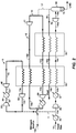
- FIG. 1 illustrates one embodiment of the present invention in which a high pressure primary expander loop 5 (i.e., an expander cycle) and a sub-cooling loop 6 are used.
- feed gas stream 10 enters the liquefaction process at a pressure less than 1,000 psia (6895 kPa), or less than about 900 psia (6205 kPa), or less than about 800 psia (5516 kPa), or less than about 700 psia (4826 kPa).
- the pressure of feed gas stream 10 will be about 800 psia (5516 kPa).
- Feed gas stream 10 generally comprises natural gas that has been treated to remove contaminants using processes and equipment that are well known in the art. After being passed through an optional external refrigerant cooling unit 35, typically at ambient cooling temperature, a portion of feed gas stream 10 is withdrawn to form side stream 11, thus providing, as will be apparent from the following discussion, a refrigerant at a pressure corresponding to the pressure of feed gas stream 10, namely any of the above pressures, including a pressure of less than 1,000 psia (6895 kPa).
- the refrigerant for the primary expander loop 5 is a portion of the methane-rich feed gas stream 10.
- a portion of the feed gas stream 10 is used as the refrigerant for expander loop 5.
- the embodiment shown in FIG. 1 utilizes a side stream that is withdrawn from feed gas stream 10 before feed gas stream 10 is passed to a compressor, the side stream 11 of feed gas to be used as the refrigerant in expander loop 5 is withdrawn from the feed gas stream 10 before the feed gas stream 10a has been passed to the initial cooling unit 35.
- the present method is any of the other embodiments herein described, wherein the portion of the feed gas stream 11 to be used as the refrigerant is withdrawn prior to the heat exchange area 50, compressed, cooled and expanded, and passed back to the heat exchange area 50 to provide at least part of the refrigeration duty for that heat exchange area 50.
- side stream 11 is passed to compression unit 20 where it is compressed to a pressure greater than or equal to 1,500 psia (10,342 kPa), thus providing a compressed refrigerant stream 12.
- side stream 11 is compressed to a pressure greater than or equal to about 1,600 psia (11,032 kPa), or greater than or equal to about 1,700 psia (11,721 kPa), or greater than or equal to about 1,800 psia (12,411 kPa), or greater than or equal to about 1,900 psia (13,100 kPa), or greater than or equal to about 2,000 psia (13,789 kPa), or greater than or equal to about 2,500 psia (17,237 kPa), or greater than or equal to about 3,000 psia (20,684 kPa), and less than 5,000 psia (34474 kPa), thus providing compressed refrigerant stream 12.
- compression unit means any one type or combination of similar or different types of compression equipment, and may include auxiliary equipment, known in the art for compressing a substance or mixture of substances.
- a “compression unit” may utilize one or more compression stages.
- Illustrative compressors may include, but are not limited to, positive displacement types, such as reciprocating and rotary compressors for example, and dynamic types, such as centrifugal and axial flow compressors, for example.
- compressed refrigerant stream 12 is passed to cooler 30 where it is cooled by indirect heat exchange with ambient air or water to provide a compressed, cooled refrigerant 12a.
- the temperature of the compressed refrigerant stream 12a as it emerges from cooler 30 depends on the ambient conditions and the cooling medium used and is typically from about 35°F (1.7°C) to about 105°F (40.6°C).
- the stream 12a is optionally passed through a supplemental cooling unit (not shown), operating with external coolant fluids, such that the compressed refrigerant stream 12a exits said cooling unit at a temperature that is cooler than the ambient temperature.
- the external refrigerant cooled compressed refrigerant stream 12a is then expanded in a turbine expander 40 before being passed to heat exchange area 50.
- expanded stream 13 may have a pressure from 100 psia (689kPa) to 1,000 psia (6895kPa) and a temperature from about -100°F (-73°C) to about -180°F (-118°C). In an illustrative example, stream 13 will have a pressure of about 302 psia (2082 kPa) and a temperature of - 162°F (-108°C).
- the power generated by the turbine expander 40 is used to offset the power required to re-compress the refrigerant in loop 5 in compressor units 60 and 20.
- the power generated by the turbine expander 40 (and, any of the turbine expanders to be used) may be in the form of electric power where it is coupled to a generator, or mechanical power through a direct mechanical coupling to a compressor unit.
- heat exchange area means any one type or combination of similar or different types of equipment known in the art for facilitating heat transfer.
- a “heat exchange area” may be contained within a single piece of equipment, or it may comprise areas contained in a plurality of equipment pieces. Conversely, multiple heat exchange areas may be contained in a single piece of equipment.
- expanded refrigerant stream 13a Upon exiting heat exchange area 50, expanded refrigerant stream 13a is fed to compression unit 60 for pressurization to form stream 13b, which is then joined with side stream 11. It will be apparent that once expander loop 5 has been filled with feed gas from side stream 11, only make-up feed gas to replace losses from leaks is required, the majority of the gas entering compressor unit 20 generally being provided by stream 13b.
- the portion of feed gas stream 10 that is not withdrawn as side stream 11 is passed to heat exchange area 50 where it is cooled, at least in part, by indirect heat exchange with expanded refrigerant stream 13 and becomes a cooled fluid stream that may comprise liquefied gas, cooled gas, and/or two-phase fluid.
- feed gas stream 10 not withdrawn as side stream 11 is passed to a compressor, such as a turbine compressor 25, and then subjected to cooling with one or more external refrigerant units 37 to remove at least a portion of the heat of compression.
- the feed gas stream 10a is compressed to a pressure greater than or equal to 2,500 psia (17237 kPa), thus providing a compressed feed gas stream 10b.
- the pressure need not exceed 3,500 psia (24132 kPa).
- Compressed feed gas stream 10b then enters heat exchange area 50 where cooling is provided by streams from primary cooling loop 5, secondary cooling loop 6, and optionally, as shown, with flash gas stream 16.
- feed gas stream 10c is passed to heat exchange area 55 for further cooling.
- the principal function of heat exchange area 55 is to sub-cool the feed gas stream.
- feed gas stream 10c is sub-cooled by a sub-cooling loop 6 (described hereinafter) to produce sub-cooled fluid stream 10d.
- Sub-cooled fluid stream 10d is then expanded to a lower pressure in expander 45, thereby cooling further said stream. A portion of fluid stream 10d is taken off for use as the loop 6 refrigerant stream 14.
- Such portion of fluid stream 10d is withdrawn in a portion not to exceed 50% of said expanded, cooled gas stream and the pressure is reduced in a reduction valve (not shown) to a range of 30 - 200 psia (207 - 1379 kPa) to produce a reduced pressure gas stream as refrigerant stream 14.
- the portion of fluid stream 10d not taken off forms stream 10e which is passed to an expander 70 to additionally cool sub-cooled fluid stream 10e to form principally a liquid fraction and a remaining vapor fraction.
- Expander 70 may be any pressure reducing device, including, but not limited to a valve, control valve, Joule-Thompson valve, Venturi device, liquid expander, hydraulic turbine, and the like.
- the largely liquefied sub-cooled stream 10e is passed to a separator, e.g., surge tank 80 where the liquefied portion 15 is withdrawn from the process as LNG having a temperature corresponding to the bubble point pressure.
- the remaining vapor portion (flash vapor) stream 16 is used as fuel to power the compressor units and may be optionally used as a refrigerant in sub-cooling loop 6, as illustrated in FIG.1 . So, prior to being used as fuel, all or a portion of flash vapor stream 16 may optionally be passed from surge tank 80 to heat exchange areas 50 and 55 to supplement the cooling provided in those heat exchange areas.
- the flash vapor stream 16 may also be used as the refrigerant, or to supplement the refrigerant, in refrigeration loop 5, not shown.
- the refrigerant stream 14 of sub-cooling loop 6 is led through heat exchange area 55 to provide part of the heat removal duty and exits as stream 14a, which in turn is provided to heat exchange area 50 for further heat removal duty.
- the thus warmed stream exits as stream 14b which is compressed in compressor unit 90, and then cooled in cooling unit 31, which can be an ambient temperature air or water external refrigerant cooler, or may comprise any other external refrigerant unit(s).
- This compressed, cooled stream 14b is then added to feed gas stream 10a, thus completing loop 6.
- sub-cooling loop 6 is a closed loop utilizing, not according to the invention, nitrogen, or nitrogen-containing gas as refrigerant stream 14.
- Stream 14 can typically be provided from bottled sources, or from other contiguous air separation and treatment processes, and will be provided typically at a temperature of about 60°F (15.6°C) to about 95°F (35°C) and a pressure of about 800 psia (5516 kPa) to about 2,500 psia (17237 kPa).
- Gaseous stream 14d is provided to expander 41 and exits expander 41 as gaseous stream 14 typically having a temperature from about -220°F (-140°C) to about -260°F (-162°C) (e.g. about -242°F (-52°C)) and a pressure of about 50 psia (345 kPa) to about 550 psia (3792 kPa).
- Stream 14 can be provided to heat exchange areas 55 and 50 as illustrated.
- the warmed stream 14b after passing through the exchange areas, is then compressed in compression unit 90 and cooled in external refrigerant cooling unit 31, which can be of the same type as ambient temperature cooler 37, so as to be approximately at the original temperature and pressure of stream 14s for merging with or comprising stream 14c.
- external refrigerant cooling unit 31 can be of the same type as ambient temperature cooler 37, so as to be approximately at the original temperature and pressure of stream 14s for merging with or comprising stream 14c.
- the re-compressed sub-cooling refrigerant stream 14b becomes stream 14c, and is passed to heat exchange area 50 where it is further cooled by indirect heat exchange with expanded refrigerant stream 13, sub-cooling refrigerant stream 14a, and, optionally, flash vapor stream 16a before returning to expander 41 as stream 14d.
- a portion of flash vapor 16 is withdrawn through line 17 to fill sub-cooling loop 6.
- a portion of the feed gas from feed gas stream 10 after liquefaction is withdrawn (in the form of flash gas from flash gas stream 16 ) for use as the refrigerant by providing into the secondary expansion cooling loop, e.g., sub-cooling loop 6.
- the secondary expansion cooling loop e.g., sub-cooling loop 6.
- the sub-cooling refrigerant stream 14b (the flash vapor stream) is then returned to compression unit 90 where it is re-compressed to a higher pressure and is warmed further.
- the re-compressed sub-cooling refrigerant stream 14b is cooled in one or more external refrigerant cooling units (e.g., an ambient temperature cooler 31, as above).
- the re-compressed sub-cooling refrigerant stream is passed to heat exchange area 50 where it is further cooled by indirect heat exchange with expanded refrigerant stream 13, sub-cooling refrigerant stream 14a, and, optionally, flash vapor stream 16.
- the present method is any of the other embodiments disclosed herein further comprising providing cooling using a closed loop (e.g., sub-cooling loop 6 ) charged with flash vapor resulting from the LNG production (e.g., flash vapor 16 ).
- Table 1 illustrates the cooling load reduction for expander loop 5 and subcooling loop 6 when the cooling loads are compared from operating the feed gas at 1,000 psia (6895 kPa) versus 3,000 psia (20684 kPa), as discussed above.
- Tables 2 and 3 below illustrate flow rate, pressures, and power consumption data using the invention process where the feed gas pressure at the entry to the primary heat exchange (e.g., 50 ) was varied from 1,000 psia (6895 kPa) to 5,000 psia (34474 kPa) while keeping the temperature at the cold end of the primary heat exchanger 50 (at 10c ) constant.
- the feed gas rate is kept constant and just enough fuel (for the embodiments in Fig 1 or Fig. 2 ) is separated to provide a fuel source for power production.
- the feed gas used in this illustrative case is predominantly methane (e.g., about 96%) with about 4% nitrogen.
- a nitrogen rejection unit (not shown) for the LNG withdrawn from separation unit 80 will be typically in use.
- the refrigerant flow rate through the primary loop 5 is reduced by more than a factor of two as the heat exchange pressure is increased from 1,000 psia (6895 kPa) to 5,000 (34474 kPa) psia.
- Table 3 shows a similar trend. The reduced flow rate enables the use of compact equipment that is particularly attractive for offshore gas processing applications.
- the optimum mode (least total compression power) was determined to be operation at about 2,750 psia (18961 kPa).
- the primary loop operating pressure for this illustrative example was fixed at 3,000 psia (20684 kPa).
Landscapes
- Engineering & Computer Science (AREA)
- Physics & Mathematics (AREA)
- Mechanical Engineering (AREA)
- Thermal Sciences (AREA)
- General Engineering & Computer Science (AREA)
- Chemical & Material Sciences (AREA)
- Chemical Kinetics & Catalysis (AREA)
- General Chemical & Material Sciences (AREA)
- Oil, Petroleum & Natural Gas (AREA)
- Separation By Low-Temperature Treatments (AREA)
Claims (7)
- Procédé de liquéfaction d'un courant de gaz, ledit procédé comprenant :(a) l'obtention dudit courant de gaz à une pression de 600-1000 psia (4137-6895 kPa) comme courant de gaz d'alimentation (10) ;(b) l'obtention d'un réfrigérant (11) à une pression de moins de 1000 psia (6895 kPa) par retrait d'une partie dudit courant de gaz à une pression de moins de 1000 psia (6895 kPa) pour utilisation comme ledit réfrigérant ;(c) la compression dudit réfrigérant jusqu'à une pression supérieure ou égale à 1500 et allant jusqu'à 5000 psia (10 342 kPa à 34 474 kPa) pour produire un réfrigérant comprimé (12) ;(d) le refroidissement dudit réfrigérant comprimé par échange de chaleur indirect (30) avec un fluide de refroidissement ;(e) la détente du réfrigérant comprimé de (d) (12a) pour refroidir encore ledit réfrigérant comprimé, pour produire un réfrigérant détendu, refroidi (13) à une pression supérieure ou égale à 100 psia (689 kPa) et inférieure ou égale à 1000 psia (6895 kPa) ;(f) le passage dudit réfrigérant détendu, refroidi jusqu'à une première zone d'échange de chaleur (50) ;(g) la compression du courant de gaz d'alimentation de (a) (10a) jusqu'à une pression supérieure ou égale à 2500 psia (17 237 kPa) et inférieure ou égale à 3500 psia (24 132 kPa) pour produire un courant de gaz d'alimentation comprimé ;(h) le refroidissement dudit courant de gaz d'alimentation comprimé par échange de chaleur indirect (37) avec un fluide de refroidissement externe ; et(i) le passage dudit courant de gaz d'alimentation comprimé (10b) de (h) à travers la première zone d'échange de chaleur (50) pour refroidir au moins une partie de celui-ci par échange de chaleur indirect avec le réfrigérant détendu, refroidi (13), pour produire un courant de gaz d'alimentation comprimé, encore refroidi (10c) ;(j) le passage du courant de gaz d'alimentation comprimé, encore refroidi de (i) à travers une deuxième zone d'échange de chaleur (55) pour un refroidissement supplémentaire ;(k) la détente (45) dudit courant de gaz d'alimentation comprimé, encore refroidi de (j) (10d) pour réduire la pression dudit courant de gaz d'alimentation jusqu'à une pression supérieure ou égale à 50 psia (345 kPa) et inférieure ou égale à 450 psia (3103 kPa) pour produire un courant de gaz détendu, refroidi ;(l) le retrait d'une partie ne dépassant pas 50 % dudit courant de gaz détendu, refroidi de (k) et la réduction de sa pression dans une vanne de réduction jusqu'à une gamme de 30-200 psia (207-1379 kPa) pour produire un courant de gaz à pression réduite, et le passage du courant de gaz à pression réduite à travers la deuxième zone d'échange de chaleur (55) de (j) comme courant de gaz de refroidissement (14) ;(m) la détente d'une autre partie dudit courant de gaz détendu, refroidi de (k) (10e) ; et(n) le passage du courant de gaz détendu, refroidi de (m) jusqu'à une cuve de séparation (80) de laquelle du gaz naturel liquide (15) est retiré et des vapeurs gazeuses restantes sont retirées comme vapeur instantanée (16) .
- Procédé de la revendication 1, comprenant en outre le passage du courant de gaz de refroidissement (14a) à travers la première zone d'échange de chaleur (50) pour aider au refroidissement dudit courant de gaz d'alimentation comprimé (10b).
- Procédé de la revendication 2, comprenant en outre la compression ultérieure (90) et le refroidissement du courant de gaz de refroidissement (14b) par échange de chaleur indirect avec une unité de refroidissement externe (31), une ou plusieurs fois, et l'ajout du courant de gaz de refroidissement au courant de gaz d'alimentation du (a) de la revendication 1 avant la compression dudit courant de gaz en (g) de la revendication 1.
- Procédé de la revendication 1 dans lequel ladite première zone d'échange de chaleur (50) et ladite deuxième zone d'échange de chaleur (55) sont alimentées avec un courant de refroidissement de boucle de sous-refroidissement à détendeur (14) entièrement chargé avec une partie de ladite vapeur instantanée (16) issue du (n) de la revendication 1.
- Procédé de la revendication 4 dans lequel ledit courant de refroidissement de boucle de sous-refroidissement à détendeur (14) circule dans une boucle fermée (6) comprenant la compression (90) dudit courant de refroidissement de boucle de sous-refroidissement à détendeur (14b) après passage à travers ladite première zone d'échange de chaleur (50) et ladite deuxième zone d'échange de chaleur (55), un refroidissement avec au moins une unité de refroidissement par réfrigérant externe (31), et la détente (41) dudit courant de refroidissement de boucle de sous-refroidissement à détendeur avant sa fourniture aux première et deuxième zones d'échange de chaleur (50, 55).
- Procédé de la revendication 5 dans lequel la partie restante de ladite vapeur instantanée (16) est passée à travers la première et/ou la deuxième zone d'échange de chaleur (50, 55) comme courant de fluide de refroidissement avant d'être acheminée pour utilisation comme source de combustible.
- Système destiné à traiter un courant de gaz d'alimentation, comprenant :(a) le courant de gaz d'alimentation (10) ayant une pression de 600-1000 psia (4137-6895 kPa) ;(b) une première boucle de réfrigération (5) ayant un courant de réfrigérant (11) à une pression de moins de 1000 psia (6895 kPa), une première unité de compression (20), un premier refroidisseur (30) configuré pour produire un courant de réfrigérant comprimé, refroidi (12a) à une pression supérieure ou égale à 1500 et allant jusqu'à 5000 psia (10 342 kPa à 34 474 kPa), et un premier détendeur (40) pour refroidir ledit réfrigérant, produisant ainsi un réfrigérant détendu, refroidi (13) à une pression supérieure ou égale à 100 psia (689 kPa) et inférieure ou égale à 1000 psia (6895 kPa), ledit courant de réfrigérant étant obtenu par retrait d'une partie dudit courant de gaz d'alimentation à une pression de moins de 1000 psia (6895 kPa) pour utilisation comme ledit réfrigérant ;(c) une deuxième unité de compression (25) configurée pour comprimer le courant de gaz d'alimentation jusqu'à une pression supérieure ou égale à 2500 psia (17 237 kPa) et inférieure ou égale à 3500 psia (24 132 kPa) pour former un courant de gaz d'alimentation comprimé ;(d) un deuxième refroidisseur (37) configuré pour refroidir le courant de gaz d'alimentation comprimé pour former un courant de gaz d'alimentation comprimé, refroidi (10b), le deuxième refroidisseur utilisant un fluide de refroidissement externe ;(e) une première zone d'échange de chaleur (50) configurée pour refroidir encore le courant de gaz d'alimentation comprimé, refroidi au moins partiellement par échange de chaleur indirect avec le courant de réfrigérant détendu, refroidi (13) pour produire un courant de gaz d'alimentation comprimé, encore refroidi (10c) ;(f) une deuxième zone d'échange de chaleur (55) configurée pour sous-refroidir au moins le courant de gaz d'alimentation comprimé, encore refroidi (10c) ;(g) un deuxième détendeur (45) configuré pour détendre le courant de gaz d'alimentation sous-refroidi, comprimé, encore refroidi (10d) pour réduire la pression à une valeur supérieure ou égale à 50 psia (345 kPa) et inférieure ou égale à 450 psia (3103 kPa) pour produire un courant de gaz détendu, refroidi, une partie ne dépassant pas 50 % dudit courant de gaz détendu, refroidi formant un gaz de refroidissement pour la deuxième zone d'échange de chaleur (55) ;(h) une vanne de réduction pour réduire la pression du gaz de refroidissement jusqu'à une gamme de 30-200 psia (207-1379 kPa), formant un courant de gaz de refroidissement (14) devant être fourni à la deuxième zone d'échange de chaleur (55) ;(i) un troisième détendeur (70) configuré pour détendre une autre partie (10e) dudit courant de gaz détendu, refroidi pour former un courant de produits ayant une fraction liquide et une fraction de vapeur restante ; et(j) une cuve de séparation de liquide (80) configurée pour séparer la fraction liquide (15) et la fraction de vapeur restante (16).
Applications Claiming Priority (2)
| Application Number | Priority Date | Filing Date | Title |
|---|---|---|---|
| US96602207P | 2007-08-24 | 2007-08-24 | |
| PCT/US2008/008027 WO2009029140A1 (fr) | 2007-08-24 | 2008-06-26 | Procédé de liquéfaction de gaz naturel |
Publications (3)
| Publication Number | Publication Date |
|---|---|
| EP2185877A1 EP2185877A1 (fr) | 2010-05-19 |
| EP2185877A4 EP2185877A4 (fr) | 2017-10-18 |
| EP2185877B1 true EP2185877B1 (fr) | 2021-01-20 |
Family
ID=40387622
Family Applications (1)
| Application Number | Title | Priority Date | Filing Date |
|---|---|---|---|
| EP08779824.5A Active EP2185877B1 (fr) | 2007-08-24 | 2008-06-26 | Procede et installation de liquefaction de gaz naturel |
Country Status (6)
| Country | Link |
|---|---|
| US (2) | US9140490B2 (fr) |
| EP (1) | EP2185877B1 (fr) |
| JP (1) | JP5725856B2 (fr) |
| BR (1) | BRPI0815707A2 (fr) |
| CA (1) | CA2695348A1 (fr) |
| WO (1) | WO2009029140A1 (fr) |
Families Citing this family (80)
| Publication number | Priority date | Publication date | Assignee | Title |
|---|---|---|---|---|
| CA2695348A1 (fr) * | 2007-08-24 | 2009-03-05 | Exxonmobil Upstream Research Company | Procede de liquefaction de gaz naturel |
| US9989304B2 (en) * | 2009-01-21 | 2018-06-05 | Conocophillips Company | Method for utilization of lean boil-off gas stream as a refrigerant source |
| US9441877B2 (en) | 2010-03-17 | 2016-09-13 | Chart Inc. | Integrated pre-cooled mixed refrigerant system and method |
| US10030908B2 (en) * | 2010-08-16 | 2018-07-24 | Korea Gas Corporation | Natural gas liquefaction process |
| JP5824229B2 (ja) * | 2011-04-08 | 2015-11-25 | 川崎重工業株式会社 | 液化システム |
| GB2486036B (en) * | 2011-06-15 | 2012-11-07 | Anthony Dwight Maunder | Process for liquefaction of natural gas |
| RU2596764C2 (ru) * | 2011-08-09 | 2016-09-10 | Эксонмобил Апстрим Рисерч Компани | Способ сжижения природного газа |
| AU2012324797C1 (en) * | 2011-10-21 | 2018-08-16 | Single Buoy Moorings Inc. | Multi nitrogen expansion process for LNG production |
| US10655911B2 (en) * | 2012-06-20 | 2020-05-19 | Battelle Energy Alliance, Llc | Natural gas liquefaction employing independent refrigerant path |
| BR112015002174A2 (pt) * | 2012-09-07 | 2017-07-04 | Keppel Offshore & Marine Tech Ct Pte Ltd | sistema e método para a liquefação de gás natural |
| KR101386543B1 (ko) * | 2012-10-24 | 2014-04-18 | 대우조선해양 주식회사 | 선박의 증발가스 처리 시스템 |
| US11408673B2 (en) | 2013-03-15 | 2022-08-09 | Chart Energy & Chemicals, Inc. | Mixed refrigerant system and method |
| KR102312640B1 (ko) | 2013-03-15 | 2021-10-13 | 차트 에너지 앤드 케미칼즈 인코포레이티드 | 혼합 냉매 시스템 및 방법 |
| US11428463B2 (en) | 2013-03-15 | 2022-08-30 | Chart Energy & Chemicals, Inc. | Mixed refrigerant system and method |
| US20160187056A1 (en) * | 2013-05-20 | 2016-06-30 | Korea Gas Corporation | Natural gas liquefaction process |
| US20140352331A1 (en) | 2013-05-30 | 2014-12-04 | Hyundai Heavy Industries Co., Ltd. | Liquefied gas treatment system |
| KR101640765B1 (ko) | 2013-06-26 | 2016-07-19 | 대우조선해양 주식회사 | 선박의 증발가스 처리 시스템 및 방법 |
| WO2014210409A1 (fr) * | 2013-06-28 | 2014-12-31 | Exxonmobil Upstream Research Company | Systèmes et procédés d'utilisation de détendeurs à flux axial |
| US20150153100A1 (en) * | 2013-12-04 | 2015-06-04 | General Electric Company | System and method for hybrid refrigeration gas liquefaction |
| CZ306376B6 (cs) * | 2014-07-15 | 2016-12-28 | Alpajar Group S.R.O. | Způsob kontinuální výroby kapalných a plynných paliv z podílu organických látek v odpadech |
| CA3063636C (fr) | 2014-07-25 | 2022-03-01 | Exxonmobil Upstream Research Company | Processus d'absorption de basculement cyclique et systeme |
| US20160076808A1 (en) * | 2014-09-15 | 2016-03-17 | Propak Systems Ltd. | Method and system for treating and liquefying natural gas |
| US10307749B2 (en) | 2014-11-11 | 2019-06-04 | Exxonmobil Upstream Research Company | High capacity structures and monoliths via paste imprinting |
| KR20160068439A (ko) * | 2014-12-05 | 2016-06-15 | 삼성전자주식회사 | 하이브리드 터치 기반 전자 장치 및 그 제어 방법 |
| EP3229938A1 (fr) | 2014-12-10 | 2017-10-18 | ExxonMobil Research and Engineering Company | Fibres de polymère incorporées dans un adsorbant dans un lit à garnissage et contacteurs en tissu, et procédés et dispositifs les utilisant |
| EP3237091B1 (fr) | 2014-12-23 | 2021-08-04 | ExxonMobil Upstream Research Company | Lits adsorbants structurés et leurs procédés de production |
| JP6415329B2 (ja) | 2015-01-09 | 2018-10-31 | 三菱重工エンジニアリング株式会社 | ガス液化装置及びガス液化方法 |
| CA2976629C (fr) | 2015-03-05 | 2023-05-23 | Shell Internationale Research Maatschappij B.V. | Catalyseur d'oxydation du methane, procede de preparation associe et procede d'utilisation associe |
| SG11201707065PA (en) | 2015-05-15 | 2017-11-29 | Exxonmobil Upstream Res Co | Apparatus and system for swing adsorption processes related thereto |
| AU2016265109B2 (en) | 2015-05-15 | 2019-03-07 | Exxonmobil Upstream Research Company | Apparatus and system for swing adsorption processes related thereto comprising mid-bed purge systems |
| US10072889B2 (en) * | 2015-06-24 | 2018-09-11 | General Electric Company | Liquefaction system using a turboexpander |
| AR105277A1 (es) | 2015-07-08 | 2017-09-20 | Chart Energy & Chemicals Inc | Sistema y método de refrigeración mixta |
| CA2996139C (fr) | 2015-09-02 | 2021-06-15 | Exxonmobil Upstream Research Company | Procede et systeme pour adsorption modulee au moyen d'un flux de tete d'un demethaniseur comme gaz de purge |
| US10080992B2 (en) | 2015-09-02 | 2018-09-25 | Exxonmobil Upstream Research Company | Apparatus and system for swing adsorption processes related thereto |
| RU2610625C1 (ru) * | 2015-10-21 | 2017-02-14 | Андрей Владиславович Курочкин | Способ сжижения природного газа |
| AU2016344415B2 (en) | 2015-10-27 | 2019-08-22 | Exxonmobil Upstream Research Company | Apparatus and system for swing adsorption processes related thereto having a plurality of valves |
| US10040022B2 (en) | 2015-10-27 | 2018-08-07 | Exxonmobil Upstream Research Company | Apparatus and system for swing adsorption processes related thereto |
| US10220346B2 (en) | 2015-10-27 | 2019-03-05 | Exxonmobil Upstream Research Company | Apparatus and system for swing adsorption processes related thereto |
| US10744449B2 (en) | 2015-11-16 | 2020-08-18 | Exxonmobil Upstream Research Company | Adsorbent materials and methods of adsorbing carbon dioxide |
| EP3390936A1 (fr) * | 2015-12-14 | 2018-10-24 | Exxonmobil Upstream Research Company | Prérefroidissement de gaz naturel par compression et dilatation haute pression |
| GB201601878D0 (en) | 2016-02-02 | 2016-03-16 | Highview Entpr Ltd | Improvements in power recovery |
| FR3048074B1 (fr) * | 2016-02-18 | 2019-06-07 | L'air Liquide, Societe Anonyme Pour L'etude Et L'exploitation Des Procedes Georges Claude | Methode pour eviter l'evaporation instantanee de gaz naturel liquefie en cours de transport. |
| ITUA20161513A1 (it) * | 2016-03-09 | 2017-09-09 | Nuovo Pignone Tecnologie Srl | Motocompressore - espantore integrato |
| AU2017234450B2 (en) | 2016-03-18 | 2020-02-06 | Exxonmobil Upstream Research Company | Apparatus and system for swing adsorption processes related thereto |
| US20190257579A9 (en) * | 2016-05-27 | 2019-08-22 | Jl Energy Transportation Inc. | Integrated multi-functional pipeline system for delivery of chilled mixtures of natural gas and chilled mixtures of natural gas and ngls |
| RU2702545C1 (ru) | 2016-05-31 | 2019-10-08 | Эксонмобил Апстрим Рисерч Компани | Устройство и система для осуществления процессов циклической адсорбции |
| EP3463620A1 (fr) | 2016-05-31 | 2019-04-10 | ExxonMobil Upstream Research Company | Appareil et système pour procédés d'adsorption modulée |
| US11112173B2 (en) * | 2016-07-01 | 2021-09-07 | Fluor Technologies Corporation | Configurations and methods for small scale LNG production |
| FR3053771B1 (fr) * | 2016-07-06 | 2019-07-19 | Saipem S.P.A. | Procede de liquefaction de gaz naturel et de recuperation d'eventuels liquides du gaz naturel comprenant deux cycles refrigerant semi-ouverts au gaz naturel et un cycle refrigerant ferme au gaz refrigerant |
| AU2017304578B2 (en) * | 2016-07-26 | 2019-12-19 | Shell Internationale Research Maatschappij B.V. | Method and apparatus for cooling down a cryogenic heat exchanger |
| SG11201901346YA (en) | 2016-08-31 | 2019-03-28 | Shell Int Research | Methane oxidation catalyst, process to prepare the same and method of using the same |
| WO2018041630A1 (fr) | 2016-08-31 | 2018-03-08 | Shell Internationale Research Maatschappij B.V. | Catalyseur d'oxydation du méthane, procédé de préparation associé et procédé d'utilisation associé |
| US10434458B2 (en) | 2016-08-31 | 2019-10-08 | Exxonmobil Upstream Research Company | Apparatus and system for swing adsorption processes related thereto |
| CN109922872A (zh) | 2016-09-01 | 2019-06-21 | 埃克森美孚上游研究公司 | 使用3a沸石结构移除水的变化吸附处理 |
| US10328382B2 (en) | 2016-09-29 | 2019-06-25 | Exxonmobil Upstream Research Company | Apparatus and system for testing swing adsorption processes |
| US20180142949A1 (en) * | 2016-11-18 | 2018-05-24 | Grant Nevison | Partial open-loop nitrogen refrigeration process and system for an oil or gas production operation |
| RU2720940C1 (ru) | 2016-12-21 | 2020-05-14 | Эксонмобил Апстрим Рисерч Компани | Самоподдерживающиеся структуры, имеющие активные материалы |
| JP7021226B2 (ja) | 2016-12-21 | 2022-02-16 | エクソンモービル アップストリーム リサーチ カンパニー | 発泡幾何構造および活性材料を有する自己支持構造 |
| JP7022140B2 (ja) * | 2017-02-13 | 2022-02-17 | エクソンモービル アップストリーム リサーチ カンパニー | 高圧圧縮及び膨張による天然ガスの予冷 |
| US11402151B2 (en) * | 2017-02-24 | 2022-08-02 | Praxair Technology, Inc. | Liquid natural gas liquefier utilizing mechanical and liquid nitrogen refrigeration |
| CA3075987A1 (fr) | 2017-09-29 | 2019-04-04 | Exxonmobil Upstream Research Company | Liquefaction de gaz naturel par un processus d'expansion a haute pression |
| AU2018342116B2 (en) | 2017-09-29 | 2021-07-22 | Exxonmobil Upstream Research Company | Natural gas liquefaction by a high pressure expansion process |
| US20190120548A1 (en) | 2017-10-25 | 2019-04-25 | Fritz Pierre, JR. | Natural Gas Liquefaction by a High Pressure Expansion Process using Multiple Turboexpander Compressors |
| JP6366870B1 (ja) * | 2018-01-17 | 2018-08-01 | レール・リキード−ソシエテ・アノニム・プール・レテュード・エ・レクスプロワタシオン・デ・プロセデ・ジョルジュ・クロード | ボイルオフガス再液化装置およびそれを備えるlng供給システム |
| US11331620B2 (en) | 2018-01-24 | 2022-05-17 | Exxonmobil Upstream Research Company | Apparatus and system for swing adsorption processes |
| WO2019168628A1 (fr) | 2018-02-28 | 2019-09-06 | Exxonmobil Upstream Research Company | Appareil et système pour procédés d'adsorption modulée |
| WO2019236246A1 (fr) | 2018-06-07 | 2019-12-12 | Exxonmobil Upstream Research Company | Pré-traitement et pré-refroidissement de gaz naturel par compression et détente à haute pression |
| KR102108924B1 (ko) * | 2018-08-21 | 2020-05-11 | 영남대학교 산학협력단 | 천연 가스 액화 처리 장치 |
| SG11202101058QA (en) | 2018-08-22 | 2021-03-30 | Exxonmobil Upstream Res Co | Heat exchanger configuration for a high pressure expander process and a method of natural gas liquefaction using the same |
| US11635252B2 (en) | 2018-08-22 | 2023-04-25 | ExxonMobil Technology and Engineering Company | Primary loop start-up method for a high pressure expander process |
| JP7154385B2 (ja) * | 2018-08-22 | 2022-10-17 | エクソンモービル アップストリーム リサーチ カンパニー | 高圧エキスパンダプロセスのための補給ガス組成変動の管理 |
| WO2020131496A1 (fr) | 2018-12-21 | 2020-06-25 | Exxonmobil Upstream Research Company | Systèmes, appareil et procédés de modulation d'écoulement pour adsorption modulée cyclique |
| EP3962641A1 (fr) | 2019-04-30 | 2022-03-09 | Exxonmobil Upstream Research Company (EMHC-N1-4A-607) | Lit adsorbant à cycle rapide |
| CA3150438A1 (fr) * | 2019-08-14 | 2021-02-18 | Shell Internationale Research Maatschappij B.V. | Procede et systeme d'echangeur de chaleur |
| WO2021071755A1 (fr) | 2019-10-07 | 2021-04-15 | Exxonmobil Upstream Research Company | Procédés et systèmes d'adsorption utilisant une commande d'élévation de pas de soupapes champignon à actionnement hydraulique |
| US11433346B2 (en) | 2019-10-16 | 2022-09-06 | Exxonmobil Upstream Research Company | Dehydration processes utilizing cationic zeolite RHO |
| RU2739754C1 (ru) * | 2020-05-28 | 2020-12-28 | Андрей Владиславович Курочкин | Установка для получения углеводородов из газовой смеси |
| WO2022099233A1 (fr) * | 2020-11-03 | 2022-05-12 | Exxonmobil Upstream Research Company | Procédés et systèmes de liquéfaction de gaz naturel comprenant une compression, une détente et un recyclage de charge |
| US20240084822A1 (en) * | 2022-09-08 | 2024-03-14 | Cnx Resources Corporation | Systems and Methods for Producing Cold CNG from Wellhead Gas Pressure |
| FR3141998A1 (fr) * | 2022-11-10 | 2024-05-17 | Engie | Dispositif et procédé de sous-refroidissement d’un gaz liquefié |
Family Cites Families (61)
| Publication number | Priority date | Publication date | Assignee | Title |
|---|---|---|---|---|
| US6889A (en) * | 1849-11-20 | Sounding-board eor pianofortes | ||
| US6694A (en) * | 1849-09-04 | scott | ||
| US3162519A (en) * | 1958-06-30 | 1964-12-22 | Conch Int Methane Ltd | Liquefaction of natural gas |
| US3223315A (en) * | 1963-01-22 | 1965-12-14 | Watt V Smith | Unitized centrifugal separator |
| US3323315A (en) | 1964-07-15 | 1967-06-06 | Conch Int Methane Ltd | Gas liquefaction employing an evaporating and gas expansion refrigerant cycles |
| DE1626325B1 (de) | 1964-11-03 | 1969-10-23 | Linde Ag | Verfahren und Einrichtung zum Verfluessigen von tiefsiedenden Gasen |
| GB1096697A (en) * | 1966-09-27 | 1967-12-29 | Int Research & Dev Co Ltd | Process for liquefying natural gas |
| US3677019A (en) | 1969-08-01 | 1972-07-18 | Union Carbide Corp | Gas liquefaction process and apparatus |
| US3735600A (en) * | 1970-05-11 | 1973-05-29 | Gulf Research Development Co | Apparatus and process for liquefaction of natural gases |
| US4179897A (en) | 1975-08-25 | 1979-12-25 | Air Products & Chemicals, Inc. | Isentropic expansion of gases via a pelton wheel |
| US4147525A (en) | 1976-06-08 | 1979-04-03 | Bradley Robert A | Process for liquefaction of natural gas |
| JPS6060463A (ja) | 1983-09-14 | 1985-04-08 | 株式会社日立製作所 | 液化ガス発生装置 |
| US4778497A (en) | 1987-06-02 | 1988-10-18 | Union Carbide Corporation | Process to produce liquid cryogen |
| FR2714722B1 (fr) | 1993-12-30 | 1997-11-21 | Inst Francais Du Petrole | Procédé et appareil de liquéfaction d'un gaz naturel. |
| CN1110394A (zh) * | 1994-04-04 | 1995-10-18 | 吉阿明 | 空气能8字循环空调机-微分冷谷管应用 |
| AUPM485694A0 (en) | 1994-04-05 | 1994-04-28 | Bhp Petroleum Pty. Ltd. | Liquefaction process |
| US5473900A (en) | 1994-04-29 | 1995-12-12 | Phillips Petroleum Company | Method and apparatus for liquefaction of natural gas |
| DE19517116C1 (de) | 1995-05-10 | 1996-06-20 | Linde Ag | Verfahren zur Verringerung des Energieverbrauchs |
| EP0857285B1 (fr) | 1995-10-05 | 2003-04-23 | BHP Petroleum Pty. Ltd. | Dispositif de liquefaction |
| US5669234A (en) | 1996-07-16 | 1997-09-23 | Phillips Petroleum Company | Efficiency improvement of open-cycle cascaded refrigeration process |
| US5755114A (en) | 1997-01-06 | 1998-05-26 | Abb Randall Corporation | Use of a turboexpander cycle in liquefied natural gas process |
| JPH10204455A (ja) | 1997-01-27 | 1998-08-04 | Chiyoda Corp | 天然ガス液化方法 |
| US5836173A (en) | 1997-05-01 | 1998-11-17 | Praxair Technology, Inc. | System for producing cryogenic liquid |
| US5931021A (en) | 1997-06-24 | 1999-08-03 | Shnaid; Isaac | Straightforward method and once-through apparatus for gas liquefaction |
| US5992175A (en) * | 1997-12-08 | 1999-11-30 | Ipsi Llc | Enhanced NGL recovery processes |
| US6446465B1 (en) | 1997-12-11 | 2002-09-10 | Bhp Petroleum Pty, Ltd. | Liquefaction process and apparatus |
| FR2772896B1 (fr) | 1997-12-22 | 2000-01-28 | Inst Francais Du Petrole | Procede de liquefaction d'un gaz notamment un gaz naturel ou air comportant une purge a moyenne pression et son application |
| FR2778232B1 (fr) * | 1998-04-29 | 2000-06-02 | Inst Francais Du Petrole | Procede et dispositif de liquefaction d'un gaz naturel sans separation de phases sur les melanges refrigerants |
| US6006545A (en) | 1998-08-14 | 1999-12-28 | L'air Liquide, Societe Anonyme Pour L'etude Et L'exploitation Des Procedes | Liquefier process |
| JP2000088455A (ja) * | 1998-09-14 | 2000-03-31 | Nippon Sanso Kk | アルゴンの回収精製方法及び装置 |
| US6269656B1 (en) | 1998-09-18 | 2001-08-07 | Richard P. Johnston | Method and apparatus for producing liquified natural gas |
| US6085545A (en) | 1998-09-18 | 2000-07-11 | Johnston; Richard P. | Liquid natural gas system with an integrated engine, compressor and expander assembly |
| TW421704B (en) | 1998-11-18 | 2001-02-11 | Shell Internattonale Res Mij B | Plant for liquefying natural gas |
| US6070429A (en) | 1999-03-30 | 2000-06-06 | Phillips Petroleum Company | Nitrogen rejection system for liquified natural gas |
| MY122625A (en) * | 1999-12-17 | 2006-04-29 | Exxonmobil Upstream Res Co | Process for making pressurized liquefied natural gas from pressured natural gas using expansion cooling |
| US6220053B1 (en) | 2000-01-10 | 2001-04-24 | Praxair Technology, Inc. | Cryogenic industrial gas liquefaction system |
| GB0006265D0 (en) | 2000-03-15 | 2000-05-03 | Statoil | Natural gas liquefaction process |
| US6367286B1 (en) | 2000-11-01 | 2002-04-09 | Black & Veatch Pritchard, Inc. | System and process for liquefying high pressure natural gas |
| US6484533B1 (en) | 2000-11-02 | 2002-11-26 | Air Products And Chemicals, Inc. | Method and apparatus for the production of a liquid cryogen |
| US6412302B1 (en) * | 2001-03-06 | 2002-07-02 | Abb Lummus Global, Inc. - Randall Division | LNG production using dual independent expander refrigeration cycles |
| US7219512B1 (en) | 2001-05-04 | 2007-05-22 | Battelle Energy Alliance, Llc | Apparatus for the liquefaction of natural gas and methods relating to same |
| US6581409B2 (en) | 2001-05-04 | 2003-06-24 | Bechtel Bwxt Idaho, Llc | Apparatus for the liquefaction of natural gas and methods related to same |
| US6742358B2 (en) | 2001-06-08 | 2004-06-01 | Elkcorp | Natural gas liquefaction |
| GB0120272D0 (en) * | 2001-08-21 | 2001-10-10 | Gasconsult Ltd | Improved process for liquefaction of natural gases |
| US6564578B1 (en) | 2002-01-18 | 2003-05-20 | Bp Corporation North America Inc. | Self-refrigerated LNG process |
| US6751985B2 (en) | 2002-03-20 | 2004-06-22 | Exxonmobil Upstream Research Company | Process for producing a pressurized liquefied gas product by cooling and expansion of a gas stream in the supercritical state |
| FR2841330B1 (fr) | 2002-06-21 | 2005-01-28 | Inst Francais Du Petrole | Liquefaction de gaz naturel avec recyclage de gaz naturel |
| US6622519B1 (en) | 2002-08-15 | 2003-09-23 | Velocys, Inc. | Process for cooling a product in a heat exchanger employing microchannels for the flow of refrigerant and product |
| US6694774B1 (en) | 2003-02-04 | 2004-02-24 | Praxair Technology, Inc. | Gas liquefaction method using natural gas and mixed gas refrigeration |
| US6889523B2 (en) | 2003-03-07 | 2005-05-10 | Elkcorp | LNG production in cryogenic natural gas processing plants |
| US6742357B1 (en) | 2003-03-18 | 2004-06-01 | Air Products And Chemicals, Inc. | Integrated multiple-loop refrigeration process for gas liquefaction |
| US6722157B1 (en) | 2003-03-20 | 2004-04-20 | Conocophillips Company | Non-volatile natural gas liquefaction system |
| US7204100B2 (en) | 2004-05-04 | 2007-04-17 | Ortloff Engineers, Ltd. | Natural gas liquefaction |
| US7866184B2 (en) * | 2004-06-16 | 2011-01-11 | Conocophillips Company | Semi-closed loop LNG process |
| US7637121B2 (en) | 2004-08-06 | 2009-12-29 | Bp Corporation North America Inc. | Natural gas liquefaction process |
| US7228714B2 (en) * | 2004-10-28 | 2007-06-12 | Praxair Technology, Inc. | Natural gas liquefaction system |
| US7673476B2 (en) | 2005-03-28 | 2010-03-09 | Cambridge Cryogenics Technologies | Compact, modular method and apparatus for liquefying natural gas |
| WO2007021351A1 (fr) | 2005-08-09 | 2007-02-22 | Exxonmobil Upstream Research Company | Procede de liquefaction de gaz naturel destine a produire un gnl |
| US8250883B2 (en) * | 2006-12-26 | 2012-08-28 | Repsol Ypf, S.A. | Process to obtain liquefied natural gas |
| CA2681417C (fr) | 2007-05-03 | 2016-07-26 | Exxonmobil Upstream Research Company | Processus de liquefaction de gaz naturel |
| CA2695348A1 (fr) * | 2007-08-24 | 2009-03-05 | Exxonmobil Upstream Research Company | Procede de liquefaction de gaz naturel |
-
2008
- 2008-06-26 CA CA 2695348 patent/CA2695348A1/fr not_active Abandoned
- 2008-06-26 EP EP08779824.5A patent/EP2185877B1/fr active Active
- 2008-06-26 WO PCT/US2008/008027 patent/WO2009029140A1/fr active Application Filing
- 2008-06-26 BR BRPI0815707 patent/BRPI0815707A2/pt not_active IP Right Cessation
- 2008-06-26 US US12/668,811 patent/US9140490B2/en active Active
- 2008-06-26 JP JP2010521838A patent/JP5725856B2/ja active Active
-
2015
- 2015-08-14 US US14/826,643 patent/US20160003529A1/en not_active Abandoned
Non-Patent Citations (1)
| Title |
|---|
| None * |
Also Published As
| Publication number | Publication date |
|---|---|
| AU2008294046A1 (en) | 2009-03-05 |
| EP2185877A1 (fr) | 2010-05-19 |
| US9140490B2 (en) | 2015-09-22 |
| US20160003529A1 (en) | 2016-01-07 |
| EP2185877A4 (fr) | 2017-10-18 |
| CA2695348A1 (fr) | 2009-03-05 |
| US20100186445A1 (en) | 2010-07-29 |
| BRPI0815707A2 (pt) | 2015-02-10 |
| WO2009029140A1 (fr) | 2009-03-05 |
| JP2010537151A (ja) | 2010-12-02 |
| JP5725856B2 (ja) | 2015-05-27 |
Similar Documents
| Publication | Publication Date | Title |
|---|---|---|
| EP2185877B1 (fr) | Procede et installation de liquefaction de gaz naturel | |
| JP5139292B2 (ja) | Lngのための天然ガス液化方法 | |
| US6378330B1 (en) | Process for making pressurized liquefied natural gas from pressured natural gas using expansion cooling | |
| CA3079890C (fr) | Liquefaction de gaz naturel par un procede d'expansion a haute pression utilisant de multiples compresseurs de turbodetendeur | |
| CA3056587C (fr) | Methode de cascade arctique pour liquefaction de gaz naturel dans un cycle haute pression avec un prerefroidissement par l'ethane et un sous-refroidissement par l'azote, et une plante pour sa mise en oeuvre | |
| WO2008136884A1 (fr) | Processus de liquéfaction de gaz naturel | |
| WO2010071449A2 (fr) | Procédé et système de production de gaz naturel liquéfié | |
| US11892233B2 (en) | Natural gas liquefaction by a high pressure expansion process | |
| CA3076605C (fr) | Liquefaction de gaz naturel au moyen d'un procede de detente a haute pression | |
| AU2008294046B2 (en) | Natural gas liquefaction process |
Legal Events
| Date | Code | Title | Description |
|---|---|---|---|
| PUAI | Public reference made under article 153(3) epc to a published international application that has entered the european phase |
Free format text: ORIGINAL CODE: 0009012 |
|
| 17P | Request for examination filed |
Effective date: 20100226 |
|
| AK | Designated contracting states |
Kind code of ref document: A1 Designated state(s): AT BE BG CH CY CZ DE DK EE ES FI FR GB GR HR HU IE IS IT LI LT LU LV MC MT NL NO PL PT RO SE SI SK TR |
|
| AX | Request for extension of the european patent |
Extension state: AL BA MK RS |
|
| DAX | Request for extension of the european patent (deleted) | ||
| RAP1 | Party data changed (applicant data changed or rights of an application transferred) |
Owner name: EXXONMOBIL UPSTREAM RESEARCH COMPANY |
|
| RA4 | Supplementary search report drawn up and despatched (corrected) |
Effective date: 20170918 |
|
| RIC1 | Information provided on ipc code assigned before grant |
Ipc: F25J 1/00 20060101AFI20170912BHEP Ipc: F25J 1/02 20060101ALI20170912BHEP |
|
| GRAP | Despatch of communication of intention to grant a patent |
Free format text: ORIGINAL CODE: EPIDOSNIGR1 |
|
| STAA | Information on the status of an ep patent application or granted ep patent |
Free format text: STATUS: GRANT OF PATENT IS INTENDED |
|
| INTG | Intention to grant announced |
Effective date: 20200923 |
|
| GRAS | Grant fee paid |
Free format text: ORIGINAL CODE: EPIDOSNIGR3 |
|
| GRAA | (expected) grant |
Free format text: ORIGINAL CODE: 0009210 |
|
| STAA | Information on the status of an ep patent application or granted ep patent |
Free format text: STATUS: THE PATENT HAS BEEN GRANTED |
|
| RAP1 | Party data changed (applicant data changed or rights of an application transferred) |
Owner name: EXXONMOBIL UPSTREAM RESEARCH COMPANY |
|
| AK | Designated contracting states |
Kind code of ref document: B1 Designated state(s): AT BE BG CH CY CZ DE DK EE ES FI FR GB GR HR HU IE IS IT LI LT LU LV MC MT NL NO PL PT RO SE SI SK TR |
|
| REG | Reference to a national code |
Ref country code: GB Ref legal event code: FG4D |
|
| REG | Reference to a national code |
Ref country code: CH Ref legal event code: EP |
|
| REG | Reference to a national code |
Ref country code: DE Ref legal event code: R096 Ref document number: 602008063672 Country of ref document: DE |
|
| REG | Reference to a national code |
Ref country code: AT Ref legal event code: REF Ref document number: 1360122 Country of ref document: AT Kind code of ref document: T Effective date: 20210215 |
|
| REG | Reference to a national code |
Ref country code: IE Ref legal event code: FG4D |
|
| REG | Reference to a national code |
Ref country code: NL Ref legal event code: FP |
|
| REG | Reference to a national code |
Ref country code: LT Ref legal event code: MG9D |
|
| REG | Reference to a national code |
Ref country code: AT Ref legal event code: MK05 Ref document number: 1360122 Country of ref document: AT Kind code of ref document: T Effective date: 20210120 |
|
| PG25 | Lapsed in a contracting state [announced via postgrant information from national office to epo] |
Ref country code: LT Free format text: LAPSE BECAUSE OF FAILURE TO SUBMIT A TRANSLATION OF THE DESCRIPTION OR TO PAY THE FEE WITHIN THE PRESCRIBED TIME-LIMIT Effective date: 20210120 Ref country code: HR Free format text: LAPSE BECAUSE OF FAILURE TO SUBMIT A TRANSLATION OF THE DESCRIPTION OR TO PAY THE FEE WITHIN THE PRESCRIBED TIME-LIMIT Effective date: 20210120 Ref country code: GR Free format text: LAPSE BECAUSE OF FAILURE TO SUBMIT A TRANSLATION OF THE DESCRIPTION OR TO PAY THE FEE WITHIN THE PRESCRIBED TIME-LIMIT Effective date: 20210421 Ref country code: FI Free format text: LAPSE BECAUSE OF FAILURE TO SUBMIT A TRANSLATION OF THE DESCRIPTION OR TO PAY THE FEE WITHIN THE PRESCRIBED TIME-LIMIT Effective date: 20210120 Ref country code: BG Free format text: LAPSE BECAUSE OF FAILURE TO SUBMIT A TRANSLATION OF THE DESCRIPTION OR TO PAY THE FEE WITHIN THE PRESCRIBED TIME-LIMIT Effective date: 20210420 Ref country code: NO Free format text: LAPSE BECAUSE OF FAILURE TO SUBMIT A TRANSLATION OF THE DESCRIPTION OR TO PAY THE FEE WITHIN THE PRESCRIBED TIME-LIMIT Effective date: 20210420 Ref country code: PT Free format text: LAPSE BECAUSE OF FAILURE TO SUBMIT A TRANSLATION OF THE DESCRIPTION OR TO PAY THE FEE WITHIN THE PRESCRIBED TIME-LIMIT Effective date: 20210520 |
|
| PG25 | Lapsed in a contracting state [announced via postgrant information from national office to epo] |
Ref country code: SE Free format text: LAPSE BECAUSE OF FAILURE TO SUBMIT A TRANSLATION OF THE DESCRIPTION OR TO PAY THE FEE WITHIN THE PRESCRIBED TIME-LIMIT Effective date: 20210120 Ref country code: AT Free format text: LAPSE BECAUSE OF FAILURE TO SUBMIT A TRANSLATION OF THE DESCRIPTION OR TO PAY THE FEE WITHIN THE PRESCRIBED TIME-LIMIT Effective date: 20210120 Ref country code: LV Free format text: LAPSE BECAUSE OF FAILURE TO SUBMIT A TRANSLATION OF THE DESCRIPTION OR TO PAY THE FEE WITHIN THE PRESCRIBED TIME-LIMIT Effective date: 20210120 Ref country code: PL Free format text: LAPSE BECAUSE OF FAILURE TO SUBMIT A TRANSLATION OF THE DESCRIPTION OR TO PAY THE FEE WITHIN THE PRESCRIBED TIME-LIMIT Effective date: 20210120 |
|
| PG25 | Lapsed in a contracting state [announced via postgrant information from national office to epo] |
Ref country code: IS Free format text: LAPSE BECAUSE OF FAILURE TO SUBMIT A TRANSLATION OF THE DESCRIPTION OR TO PAY THE FEE WITHIN THE PRESCRIBED TIME-LIMIT Effective date: 20210520 |
|
| REG | Reference to a national code |
Ref country code: DE Ref legal event code: R097 Ref document number: 602008063672 Country of ref document: DE |
|
| PG25 | Lapsed in a contracting state [announced via postgrant information from national office to epo] |
Ref country code: CZ Free format text: LAPSE BECAUSE OF FAILURE TO SUBMIT A TRANSLATION OF THE DESCRIPTION OR TO PAY THE FEE WITHIN THE PRESCRIBED TIME-LIMIT Effective date: 20210120 Ref country code: EE Free format text: LAPSE BECAUSE OF FAILURE TO SUBMIT A TRANSLATION OF THE DESCRIPTION OR TO PAY THE FEE WITHIN THE PRESCRIBED TIME-LIMIT Effective date: 20210120 |
|
| PLBE | No opposition filed within time limit |
Free format text: ORIGINAL CODE: 0009261 |
|
| STAA | Information on the status of an ep patent application or granted ep patent |
Free format text: STATUS: NO OPPOSITION FILED WITHIN TIME LIMIT |
|
| PG25 | Lapsed in a contracting state [announced via postgrant information from national office to epo] |
Ref country code: RO Free format text: LAPSE BECAUSE OF FAILURE TO SUBMIT A TRANSLATION OF THE DESCRIPTION OR TO PAY THE FEE WITHIN THE PRESCRIBED TIME-LIMIT Effective date: 20210120 Ref country code: SK Free format text: LAPSE BECAUSE OF FAILURE TO SUBMIT A TRANSLATION OF THE DESCRIPTION OR TO PAY THE FEE WITHIN THE PRESCRIBED TIME-LIMIT Effective date: 20210120 Ref country code: ES Free format text: LAPSE BECAUSE OF FAILURE TO SUBMIT A TRANSLATION OF THE DESCRIPTION OR TO PAY THE FEE WITHIN THE PRESCRIBED TIME-LIMIT Effective date: 20210120 Ref country code: DK Free format text: LAPSE BECAUSE OF FAILURE TO SUBMIT A TRANSLATION OF THE DESCRIPTION OR TO PAY THE FEE WITHIN THE PRESCRIBED TIME-LIMIT Effective date: 20210120 |
|
| 26N | No opposition filed |
Effective date: 20211021 |
|
| REG | Reference to a national code |
Ref country code: DE Ref legal event code: R119 Ref document number: 602008063672 Country of ref document: DE |
|
| PG25 | Lapsed in a contracting state [announced via postgrant information from national office to epo] |
Ref country code: MC Free format text: LAPSE BECAUSE OF FAILURE TO SUBMIT A TRANSLATION OF THE DESCRIPTION OR TO PAY THE FEE WITHIN THE PRESCRIBED TIME-LIMIT Effective date: 20210120 |
|
| REG | Reference to a national code |
Ref country code: CH Ref legal event code: PL |
|
| GBPC | Gb: european patent ceased through non-payment of renewal fee |
Effective date: 20210626 |
|
| PG25 | Lapsed in a contracting state [announced via postgrant information from national office to epo] |
Ref country code: SI Free format text: LAPSE BECAUSE OF FAILURE TO SUBMIT A TRANSLATION OF THE DESCRIPTION OR TO PAY THE FEE WITHIN THE PRESCRIBED TIME-LIMIT Effective date: 20210120 |
|
| REG | Reference to a national code |
Ref country code: BE Ref legal event code: MM Effective date: 20210630 |
|
| PG25 | Lapsed in a contracting state [announced via postgrant information from national office to epo] |
Ref country code: LU Free format text: LAPSE BECAUSE OF NON-PAYMENT OF DUE FEES Effective date: 20210626 |
|
| PG25 | Lapsed in a contracting state [announced via postgrant information from national office to epo] |
Ref country code: LI Free format text: LAPSE BECAUSE OF NON-PAYMENT OF DUE FEES Effective date: 20210630 Ref country code: IT Free format text: LAPSE BECAUSE OF FAILURE TO SUBMIT A TRANSLATION OF THE DESCRIPTION OR TO PAY THE FEE WITHIN THE PRESCRIBED TIME-LIMIT Effective date: 20210120 Ref country code: IE Free format text: LAPSE BECAUSE OF NON-PAYMENT OF DUE FEES Effective date: 20210626 Ref country code: GB Free format text: LAPSE BECAUSE OF NON-PAYMENT OF DUE FEES Effective date: 20210626 Ref country code: DE Free format text: LAPSE BECAUSE OF NON-PAYMENT OF DUE FEES Effective date: 20220101 Ref country code: CH Free format text: LAPSE BECAUSE OF NON-PAYMENT OF DUE FEES Effective date: 20210630 |
|
| PG25 | Lapsed in a contracting state [announced via postgrant information from national office to epo] |
Ref country code: IS Free format text: LAPSE BECAUSE OF FAILURE TO SUBMIT A TRANSLATION OF THE DESCRIPTION OR TO PAY THE FEE WITHIN THE PRESCRIBED TIME-LIMIT Effective date: 20210520 |
|
| PG25 | Lapsed in a contracting state [announced via postgrant information from national office to epo] |
Ref country code: BE Free format text: LAPSE BECAUSE OF NON-PAYMENT OF DUE FEES Effective date: 20210630 |
|
| PG25 | Lapsed in a contracting state [announced via postgrant information from national office to epo] |
Ref country code: HU Free format text: LAPSE BECAUSE OF FAILURE TO SUBMIT A TRANSLATION OF THE DESCRIPTION OR TO PAY THE FEE WITHIN THE PRESCRIBED TIME-LIMIT; INVALID AB INITIO Effective date: 20080626 Ref country code: CY Free format text: LAPSE BECAUSE OF FAILURE TO SUBMIT A TRANSLATION OF THE DESCRIPTION OR TO PAY THE FEE WITHIN THE PRESCRIBED TIME-LIMIT Effective date: 20210120 |
|
| P01 | Opt-out of the competence of the unified patent court (upc) registered |
Effective date: 20230518 |
|
| PGFP | Annual fee paid to national office [announced via postgrant information from national office to epo] |
Ref country code: NL Payment date: 20230626 Year of fee payment: 16 Ref country code: FR Payment date: 20230622 Year of fee payment: 16 |