EP2182234B2 - Doppelkupplungsanordnung für ein Doppelkupplungsgetriebe - Google Patents
Doppelkupplungsanordnung für ein Doppelkupplungsgetriebe Download PDFInfo
- Publication number
- EP2182234B2 EP2182234B2 EP09174110.8A EP09174110A EP2182234B2 EP 2182234 B2 EP2182234 B2 EP 2182234B2 EP 09174110 A EP09174110 A EP 09174110A EP 2182234 B2 EP2182234 B2 EP 2182234B2
- Authority
- EP
- European Patent Office
- Prior art keywords
- hub
- input member
- input
- friction clutch
- clutch
- Prior art date
- Legal status (The legal status is an assumption and is not a legal conclusion. Google has not performed a legal analysis and makes no representation as to the accuracy of the status listed.)
- Active
Links
Images

Classifications
-
- F—MECHANICAL ENGINEERING; LIGHTING; HEATING; WEAPONS; BLASTING
- F16—ENGINEERING ELEMENTS AND UNITS; GENERAL MEASURES FOR PRODUCING AND MAINTAINING EFFECTIVE FUNCTIONING OF MACHINES OR INSTALLATIONS; THERMAL INSULATION IN GENERAL
- F16D—COUPLINGS FOR TRANSMITTING ROTATION; CLUTCHES; BRAKES
- F16D25/00—Fluid-actuated clutches
- F16D25/06—Fluid-actuated clutches in which the fluid actuates a piston incorporated in, i.e. rotating with the clutch
- F16D25/062—Fluid-actuated clutches in which the fluid actuates a piston incorporated in, i.e. rotating with the clutch the clutch having friction surfaces
- F16D25/063—Fluid-actuated clutches in which the fluid actuates a piston incorporated in, i.e. rotating with the clutch the clutch having friction surfaces with clutch members exclusively moving axially
- F16D25/0635—Fluid-actuated clutches in which the fluid actuates a piston incorporated in, i.e. rotating with the clutch the clutch having friction surfaces with clutch members exclusively moving axially with flat friction surfaces, e.g. discs
- F16D25/0638—Fluid-actuated clutches in which the fluid actuates a piston incorporated in, i.e. rotating with the clutch the clutch having friction surfaces with clutch members exclusively moving axially with flat friction surfaces, e.g. discs with more than two discs, e.g. multiple lamellae
-
- F—MECHANICAL ENGINEERING; LIGHTING; HEATING; WEAPONS; BLASTING
- F16—ENGINEERING ELEMENTS AND UNITS; GENERAL MEASURES FOR PRODUCING AND MAINTAINING EFFECTIVE FUNCTIONING OF MACHINES OR INSTALLATIONS; THERMAL INSULATION IN GENERAL
- F16D—COUPLINGS FOR TRANSMITTING ROTATION; CLUTCHES; BRAKES
- F16D25/00—Fluid-actuated clutches
- F16D25/10—Clutch systems with a plurality of fluid-actuated clutches
-
- F—MECHANICAL ENGINEERING; LIGHTING; HEATING; WEAPONS; BLASTING
- F16—ENGINEERING ELEMENTS AND UNITS; GENERAL MEASURES FOR PRODUCING AND MAINTAINING EFFECTIVE FUNCTIONING OF MACHINES OR INSTALLATIONS; THERMAL INSULATION IN GENERAL
- F16D—COUPLINGS FOR TRANSMITTING ROTATION; CLUTCHES; BRAKES
- F16D21/00—Systems comprising a plurality of actuated clutches
- F16D21/02—Systems comprising a plurality of actuated clutches for interconnecting three or more shafts or other transmission members in different ways
- F16D21/06—Systems comprising a plurality of actuated clutches for interconnecting three or more shafts or other transmission members in different ways at least two driving shafts or two driven shafts being concentric
- F16D2021/0661—Hydraulically actuated multiple lamellae clutches
-
- F—MECHANICAL ENGINEERING; LIGHTING; HEATING; WEAPONS; BLASTING
- F16—ENGINEERING ELEMENTS AND UNITS; GENERAL MEASURES FOR PRODUCING AND MAINTAINING EFFECTIVE FUNCTIONING OF MACHINES OR INSTALLATIONS; THERMAL INSULATION IN GENERAL
- F16D—COUPLINGS FOR TRANSMITTING ROTATION; CLUTCHES; BRAKES
- F16D2250/00—Manufacturing; Assembly
Definitions
- the present invention relates to a dual clutch transmission with a dual clutch arrangement, a hub shell being specially designed.
- the present invention also relates to a double clutch arrangement for a double clutch transmission, in which the input members of friction clutches are specially designed and arranged.
- the present invention also relates to a method for adjusting a clearance of double clutch arrangements in such double clutch transmissions.
- a dual clutch transmission according to the preamble of claim 1 is from the document US 6,378,675 B1 known.
- a double clutch arrangement with piston / cylinder arrangements fixed to the housing is from the document DE 10 2004 061 020 A1 known.
- Double clutch transmissions have a double clutch arrangement and two sub-transmissions.
- the sub-transmissions are usually designed as a countershaft design.
- One of the sub-transmissions is assigned to even gear steps, the other sub-transmission is assigned to uneven gear steps.
- This type of dual clutch transmission is suitable for motor vehicles, in particular for passenger cars.
- fluidically operated (wet) friction clutches for example wet multi-plate clutches
- wet multi-plate clutches are generally used in double clutch arrangements.
- a double clutch arrangement is known in which the two friction clutches are each assigned an accompanying actuating piston, and the actuating pistons have a first radial active surface facing a pressurizable piston chamber and a second radial active surface facing a centrifugal force pressure compensation chamber.
- the supply of fluid to the piston chambers takes place via a co-rotating hub and a rotary leadthrough arranged between this hub and the housing.
- the disadvantage of this type of double clutch arrangement is the fact that the complexity is relatively great and there are high drag torques.
- a comparable double clutch arrangement is from the document DE 102 23 780 C1 known.
- the document EP 1 568 906 A1 disclosed a double clutch with two clutches rotatable about a common axis of rotation and axially one behind the other.
- the clutches have a common driven outer disk carrier and each one driven inner disk carrier.
- a tension sleeve is provided which encompasses the outer disk carrier and via which one of the two clutches can be actuated.
- the document also discloses DE 10 2004 055 361 A1 a double clutch arrangement with two friction clutches nested radially one inside the other, each of which can be actuated fluidically.
- Each clutch is assigned a centrifugal force compensation chamber which is connected to a valve arrangement via a common line.
- the hub shell is usually made of steel, for example by cutting, from solid material. Steel is expensive. The processing is complex, time-consuming and costly. The weight of the steel hub shell is relatively large, so that drag moments can already occur at the hub shell.
- the multi-disc clutch body essentially consists of two multi-disc combs that mesh with one another. Depending on the design and arrangement of the disk carriers, the distance between the clutch body and the clutch actuator varies to a greater or lesser extent. This clearance must be set individually.
- a multi-stage automatic transmission has a drive shaft, an output shaft, three individual planetary gear sets arranged next to one another in series, and five shifting elements.
- a sun gear of the third gear set can be fixed to a transmission housing via the first shift element.
- the drive shaft is connected to a sun gear of the second gear set and can be connected to a sun gear of the first gear set via the second shift element and / or via the fifth gear set to a web of the first gear set.
- the sun gear of the first gear set can be fixed to the transmission housing via the third shift element and / or the web of the first gear set can be fixed via the fourth shift element.
- the output shaft is connected to a ring gear of the first gear set and one of the webs of the second or third gear set.
- the second and fifth switching elements form a subassembly, each with a disk pack and a servo device, as well as a disk carrier common to both switching elements.
- the disk set of the second shift element has a larger diameter than the disk set of the fifth shift element.
- the object of the present invention is to specify an improved double clutch arrangement for a double clutch transmission.
- the hub shell material according to the present invention is merely reshaped, namely by means of sheet metal by deep drawing. Mass moments of inertia are significantly reduced, since the hub shell preferably has a constant material thickness and in particular a cylindrical shape.
- the hub shell can therefore be manufactured in a cost-effective and weight-optimized manner.
- the hub shell is a formed sheet metal component, preferably with an essentially constant material thickness of 3 mm.
- the weight is significantly lower than that of a conventional hub shell made of steel. Since the material thickness is essentially constant, the hub shell is for the most part cylindrical. The mass distribution is so favorable that negatively affecting mass moments of inertia, which are caused in particular by mass lying relatively far outside in the radial direction, are (almost) completely eliminated.
- the hub shell has a first cylindrical axial section with a substantially constant inner and outer radius, the piston / cylinder arrangements being attached to the outside of the first axial section in a rotationally fixed manner.
- a cylindrical body is easy to manufacture by forming.
- the components to be mounted on the hub shell all have the same passage opening diameter, so that coupling manufacturers can construct different types of double clutch with one and the same components.
- the variety of components remains manageable, and a modular component diversity is limited as far as possible.
- the hub shell has a second axial section with a substantially constant inner and outer radius, which adjoins the first axial section, which is rotatably mounted on the inside by means of a radial bearing on the hub and which, on the outside, preferably has a circumferential pump toothing that is rolled or stamped on.
- the second axial section is also essentially cylindrical, a hub shell designed in this way can be produced simply by deep drawing.
- the second axial section essentially serves to accommodate the radial bearing in order to support the hub shell on the hub such that it can rotate in the radial and / or axial direction.
- the first and the second axial section have different inside diameters.
- one of the input members can be connected to a radially oriented transition section provided between the first and second axial sections.
- Circumferential recesses (grooves) in the hub shell which would have to be produced by machining, are not required.
- a double clutch arrangement for a double clutch transmission having an input shaft, a first friction clutch, a second friction clutch, two output shafts, a hub fixed to the housing, a first piston / cylinder arrangement and a second piston / cylinder arrangement.
- Input members of the friction clutches are coupled to the input shaft.
- Output members of the friction clutches are each connected to one of the output shafts.
- the friction clutches can each be actuated by means of one of the piston / cylinder arrangements.
- a hub shell rotatably mounted on the hub is provided.
- At least a first, a second and a third input member are provided, the first input member carrying an inner member of the radially outer friction clutch.
- the second input member is rotatably coupled to the first input member and carries an inner member of the radially inner friction clutch.
- the third input member is rotatably connected at one end to the hub and at its other end to the second input member and externally to the first input member.
- friction clutches are multi-disk clutches.
- first and the second input member are each designed in such a way that they form a counter-bearing when the friction clutches assigned to them are actuated.
- the input member of the outer friction clutch has external teeth for insertion into internal teeth of the input shaft, the input shaft preferably carrying a radial bearing and a shaft seal on the outside.
- the above object is achieved by a method for setting a clearance in a double clutch arrangement according to one of the preceding claims, wherein the input member assigned to a respective one of the friction clutches is designed such that it forms a counter-bearing for the assigned friction clutch.
- the method comprises the following steps: fixing one of the input members relative to the hub; rotationally fixed mounting of the piston / cylinder arrangement on the hub or on the hub shell; Setting a desired clutch play by axially moving the input member on the input member which has been fixed relative to the hub when the desired play is set.
- the clearance according to the present invention can be changed by simply moving the input member axially, the clearance of which is to be adjusted. This input element is then fixed and the (pre) assembly of the double clutch arrangement is continued.
- the double clutch arrangement is built up in steps radially from the inside to the outside.
- the input member, which is connected to the friction clutch, the clearance of which is to be adjusted, is, as is customary in normal construction, simply fixed at the point provided for this purpose, the input member of which is moved in the axial direction beforehand to vary the clearance.
- the measurement of the clearance and the axial movement can take place simultaneously, so that almost no time is lost in setting the clearance when the double clutch is set up. Fewer components have to be kept available. For example, the additional slats are not required.
- the following steps are carried out in particular: fixing the third input member relative to the hub; Assembling the piston / cylinder assembly associated with the external friction clutch; Installing the second input member with an associated friction clutch body; Assembling the piston / cylinder assembly associated with the internal friction clutch; selectively adjusting the clutch play of the inner friction clutch by axially displacing the second input member; Fixing the second input member on the third input member; Installing the output member of the inner friction clutch; Installing the output member of the outer friction clutch including the friction clutch body of the outer friction clutch; selectively adjusting the clutch play of the outer friction clutch by axially displacing the third input member; and fixing the first input member to the third input member.
- both or only one of the release clearances can be achieved can be set quickly and easily when building the double clutch arrangement.
- the construction or assembly of the double clutch can take place simultaneously with the measurement of the clearance, so that you can save a lot of time when assembling the double clutch.
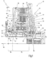
- a drive train 10 with a drive motor 12 (vg. Fig. 2 ), such as an internal combustion engine, is explicitly in the Fig. 1 not shown, but still as present to view.
- the drive train 10 also has a dual clutch transmission 14, the input of which is connected to a crankshaft 16 (cf. Fig. 2 ) of the internal combustion engine 12 is connected.
- the dual clutch transmission 14 has an output shaft 18 which can be connected to drive wheels of the vehicle in a manner known per se.
- the dual clutch transmission 14 has a dual clutch arrangement 20 which is received in a housing.
- a clutch cover 22 is shown as part of the housing.
- the double clutch arrangement 20 includes a first friction clutch 24 and a second friction clutch 26.
- the two friction clutches 24, 26 are arranged radially nested one inside the other, the first friction clutch 24 lying radially on the outside.
- the first friction clutch 24 has a first input member 28 which is coupled to the input, ie to the crankshaft 16.
- the first input member 28 is non-rotatably connected to a drive plate 29.
- the drive plate 29, which extends essentially in the radial direction, has a drive projection or ring 17 with an internal toothing 17 'in the axial direction. With the help of the internal toothing 17 ', the drive plate 29 can be attached to the crankshaft 16 (in Fig. 1 not shown) couple, which in turn has an external toothing, not shown here.
- the axial length of the ring 17 is chosen so that the shaft seal bearing 98 and the radial bearing 59 (or 96 in Fig. 2 ) can be attached to the outside of the ring 17, the length of the internal toothing being selected accordingly.
- the ring 17 is much shorter than in the prior art.
- the first input member 28 extends axially in the manner of a basket.
- the two friction clutches 24, 26 are arranged radially inside the first input member 28.
- the first friction clutch 24 also has a first output member 30.
- the first output member 30 is connected to a first output shaft 32 of the double clutch arrangement.
- the output shaft 32 is designed as a solid shaft and is connected to a first partial transmission 34 (see also Fig. 2 ) of the dual clutch transmission 14 connected.
- the first output member 30 is also designed in the manner of a basket and extends radially inside the first input member 28, the first friction clutch 24 being received therebetween.
- the second friction clutch 26 has a second input member 38.
- the second input member 38 is non-rotatably connected to the first input member 28, as is shown here by way of an example by a welded connection 39 shown in triangular form.
- the second friction clutch 26 also has a second output member 40.
- the second output member is also designed in the manner of a basket and extends radially inside the first output member 30.
- the second output member 40 is connected to a second output shaft 42 which is arranged as a hollow shaft concentric to the first output shaft 32.
- the second output shaft 42 is connected to a second partial transmission 44 (cf. Fig. 2 ) of the dual clutch transmission 14 connected.
- the first input member 28 including the drive plate 29, the first output member 30 and the second output member 40 extend, as mentioned above, in the manner of baskets starting from the area of the crankshaft 16 in the direction of the sub-transmissions 34, 44 or the output shaft
- the double clutch arrangement 20 has a hub 46 fixed to the housing, which extends in the axial direction from the area of the sub-transmissions 34, 44 in the direction of the area of the crankshaft 16.
- the hub 46 has an essentially cylindrical shape in the area of the double clutch arrangement 20.
- the hub 46 fixed to the housing is arranged coaxially to the two output shafts 32, 42 and surrounds them here.
- Axial bearings are provided between an end face of the hub 46 fixed to the housing and radial sections of the output members 30, 40 and a radial section of the drive plate 29. These axial bearings are aligned in the radial direction with a hub shell 48 that is rotatably mounted relative to the hub 46.
- the hub shell 48 is cylindrical in the area of the double clutch arrangement 14 and is arranged coaxially to the output shafts 32, 42.
- the hub shell 48 is formed here from sheet metal, preferably 3-5 mm thick. In the prior art, steel hub shells are machined produced, the conventional hub shells having different cross-sections (with varying radius) from a uniform cylinder cross-section in order to be able to accommodate a wide variety of coupling elements (eg bearings, actuators, etc.) at different radial distances.
- the hub shell 48 according to the present invention has a constant inner radius Ri and a constant outer radius Ra - at least in the area of the double clutch arrangement 14, which is essentially enclosed by the input member 28 and the drive plate 29.
- the hub shell 48 can furthermore have a toothing 50, preferably formed in one piece, at its end opposite the output shaft 18.
- This toothing 50 can mesh with a corresponding toothing, for example a hydraulic pump 50, not shown here, in order to guide fluids, which are required for actuating and / or lubricating the double clutch arrangement 14, through individual openings 52 in the hub shell 48.
- the openings 52 of which in the Fig. 1 three shown can be drilled or punched, for example.
- the openings 52 are in fluid communication with a central channel 54 and circumferentially provided grooves in the hub 46. The fluid is passed through the hub 46 into the dual clutch assembly 14 through the openings 52.
- the openings 52 are located here in a first axial section 55 of the hub shell 48, on which a large number of the relevant elements of the double clutch arrangement 14 are mounted with a constant (hub shell) radius.
- a second axial section 56 connects to the first axial section 55.
- the second axial section 56 is connected to the first axial section 55 via a radial section 57.
- the radius of the second axial section 56 is larger here than the radius of the first axial section 55 in order to be able to accommodate a radial bearing 58 between the hub shell 48 and the hub 46.
- the components 590, 55 -57 are formed in one piece here.
- the pump teeth can be rolled on or stamped on.
- the double clutch arrangement 14 is essentially supported on the hub 46.
- a second radial bearing 59 is arranged on the opposite side in the area of the clutch cover 22 fixed to the housing. In this way, a large number of the elements of the double clutch arrangement 20 can be held rotating about the hub 46.
- the first input member 28 On its side facing away from the input shaft 16, the first input member 28 is here also connected (axially) to the radial section 57 of the hub shell 48 by means of an exemplary welded connection. Alternatively and in addition, the first input member 28 could also be connected to the first axial section 55.
- the hub shell 48 could also have a constant, single radius (Ri and Ra), so that the axial sections 55, 56 would be one, i.e. would be provided without the radial section 57.
- the radial bearing 58 could be provided in a correspondingly designed recess in the hub 46.
- a great advantage of the hub shell 48 is that it can be produced from a relatively inexpensive sheet metal material, e.g. 3 mm thick sheet metal, by means of forming processes. Since the hub shell 48 has an almost constant radius, many identical components, in particular with the same through-opening radii, can be used. Such parts are explained below.
- the radial bearing 58 is provided to support the second input member 38, and thus indirectly also the first input member 28. Although the radial bearing 58 essentially absorbs radial forces, it can also be designed to absorb axial forces.
- a first piston / cylinder arrangement 60 and a second piston / cylinder arrangement 62 are provided for actuating the two friction clutches 24, 26.
- the piston / cylinder arrangements 60, 62 are arranged on opposite sides at the same radius (relative to the common axis of rotation of the overall system).
- the first piston / cylinder arrangement 60 has a first piston 64 which is mounted displaceably in the first cylinder 66 in the axial direction.
- a cylinder space formed in this way is connected via one of the radial openings 52 in the hub shell 48 to the supply line 54 within the hub 46 fixed to the housing.
- the outside of the first piston 64 is coupled to a first pressure plate 68.
- the first pressure plate 68 extends radially outward and has axial sections.
- a radially outer axial section of the pressure plate 68 is designed to axially apply a force (cf. arrow 69) to the first friction clutch 24 in order to close the friction clutch 24, which is in the Fig. 1 is shown in an open condition.
- the first pressure plate 68 rotates with the first and second input members 28, 38.
- the pressure plate 68 also rotates with the piston 64 fixed on the hub shell or the cylinder 66 fixed on the hub shell.
- the upper axial section of the first pressure plate 68 which can abut the disks of the first friction clutch 24, extends through an opening (not shown here) in a radial section of the second input member 38.
- an opening not shown here
- a plurality of such openings will generally be provided, which are arranged distributed over the circumference of the first pressure plate 68.
- a T-shaped rotary member 70 with an inner channel 72 for supplying fluid is provided on a side opposite the first piston / cylinder arrangement 60.
- a first spring arrangement 74 is provided between the piston 64 and the left side of the rotary member 70 in order to bias the first pressure plate 68 into an open position.
- the first spring arrangement 74 is supported on a radial web of the rotary member 70 and presses the piston 64, and thus also the first pressure plate 68, in the axial direction away from the radial section, in the direction of the partial transmissions 34, 44 (cf. . Fig. 2 ).
- hydraulic fluid is supplied to the first piston / cylinder arrangement 60, so that the first piston 64 is moved in the opposite direction and consequently exerts an axial force on the disk set of the first friction clutch 24 via the first pressure plate 68.
- the second piston / cylinder arrangement 62 is constructed in a corresponding manner, preferably from the same components, approximately in a mirror image of this.
- the first and second piston / cylinder assemblies 60, 62 can thus be similar or identical Components are realized, in particular with the same passage opening radius, so that there is a high modularity and a low diversity.
- the second piston / cylinder arrangement 62 accordingly has a second cylinder 78 which is connected in a rotationally fixed manner to the hub shell 46, to be precise essentially adjacent to the second output member 40.
- the second piston / cylinder arrangement 82 furthermore has a second piston 76 which acts on a second pressure plate 80.
- a radial section of the second pressure plate 80 rests against a disk set of the second, radially inner friction clutch 26.
- the second piston / cylinder arrangement 62 can consequently exert a second axial force (cf. arrow 82) on the second friction clutch 26, the second axial force being oriented opposite to the first axial force.
- a second spring arrangement 84 is provided between a further radial section of the rotary member 70 and the piston 78 of the second piston / cylinder arrangement 62, which preloads the piston 78, and thus also the second pressure plate 80, towards the input shaft 16.
- the cylinder space of the second piston / cylinder arrangement 62 is connected to the channel 54 in the hub 46 via the radial opening 52 (far right) in the hub shell 48. It goes without saying that a hydraulic circuit not shown here also has channels via which cooling fluid can be supplied to the friction clutches 24, 26.
- the cooling fluid is conveyed through channels in the hub 46 fixed to the housing, among other things. a space in the area of the rotary member 70 and the radial channels 72 in the rotary member 70 and the friction clutches 24, 26. It goes without saying that suitable radial openings are provided in each of the input and output members 38, 30, 40 in order to ensure a suitable flow of air through the lamellae.
- Double clutch arrangement 20 can also be used for dry-running friction clutches.
- cooling air could be supplied, for example, via ducts that are used to supply cooling oil in wet-running clutches.
- a modular system of double clutch arrangements can thus be built up, which are equipped with wet-running or dry-running friction clutches.
- the basic structure can be used for one or the other variant.
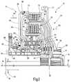
- a further dual clutch arrangement 20 is shown which reflects a separate invention.
- the internal combustion engine 12 the input shaft (crankshaft) 16 and the sub-transmissions 34, 44 are also shown.
- the double clutch assembly 20 is the Fig. 1 identical to the double clutch arrangement of the Fig. 1 built up.
- the first input member 28 is formed here continuously, so that on the drive plate 29 of the Fig. 1 can be dispensed with.
- the first input member 28 is connected to the third input member 90 by means of an exemplary welded connection 39 ′, which in turn is connected to the housing jacket 48 by means of an exemplary welded connection.
- the third input member 90 is also connected to the second input member 38 by means of an exemplary welded connection 39.
- Both the first input member 28 and the second input member 38 have knee-shaped bulges in the area of the multi-disc clutch packs in the direction of the clutch bodies. These knee-shaped bulges serve as counter bearings 92 and 94 when the first friction clutch 24 and the second friction clutch 26 are actuated. Retaining rings or the like, as known from the prior art, are not required to fix the friction clutch bodies on the disk carrier.
- a clearance s1 is defined between the clutch body of the second friction clutch 26 and the second pressure plate 80.
- a further clearance s2 is defined between the clutch body of the first, radially outer friction clutch 26 and the first pressure plate 68.
- each friction clutch 24, 26 can be set in a simple manner during the assembly of the double clutch arrangement 20 itself, as is also the case in connection with the flowchart of FIG Fig. 4 will be explained in more detail.
- the double clutch arrangement 20 is applied from the radial inside in the axial direction (from left to right in Fig. 2 ) radially outwards (upwards in Fig. 2 ) (pre-) assembled.
- the third input member 90 is fixed on the hub shell 48.
- This third input element 90 serves as a reference element for the two other input elements 28 and 38.
- the first piston / cylinder arrangement 60 is mounted in a fixed manner on the hub jacket.
- the first pressure plate 68 is then installed.
- the second input member 38 including the inner disks of the second friction clutch 26 is then installed.
- the second input member 38 serves as an inner disk carrier of the second friction clutch 26.
- the second spring arrangement 84 and the second piston / cylinder arrangement 62 including the second pressure plate 80 are then installed.
- the second input member 38 is meanwhile still freely movable in the axial direction with respect to the third input member 90, so that the clearance s1 of the second friction clutch 26 can be set as desired.
- the second input member 38 can be fixed to the third input member 90, for example with a welded connection 39.
- the second output member 40, the first output member 30 with the inner disks of the first friction clutch 24 and the first input member 28 with the outer disks of the first friction clutch 24 are mounted.
- the first input member 28 is still freely axially (and also radially) movable relative to the third input member 90.
- the clearance s2 of the first friction clutch 24 is then set.
- the disk body of the first friction clutch 24 can be brought into abutment against the first pressure plate 68 in a first step, a reference point being defined on the third input member 90 and then the first input member 28 axially forward in the clearance s2 above the third input member 90 (also moved in the direction of the motor 12).
- the first input member 28 can then be welded to the third input member 39, for example, in order to fix the elements in relation to one another.
- the double clutch arrangement 20 of Fig. 2 could also be built with piston / cylinder assemblies 60, 62 fixed to the housing.
- the piston / cylinder assemblies 60, 62 would then be mounted directly on the hub 46, additional radial bearings may then be required in the area of the rotary member 70, as shown in FIG DE 10 2006 010 113 B4 is shown, to which reference is made with regard to the structure of a double clutch assembly with non-rotatable piston / cylinder assemblies.
- the third input member 90 would then have to be shaped, for example, in such a way that it rests against a suitably constructed radial bearing, preferably invariably in the axial direction.
- the third input member would then, for example, have a roughly S-shaped cross section, with an upper, radially outer axial section serving to connect to the first input member 28 and the second input member 38 and a rear, radially inner axial section cooperating with the correspondingly designed radial bearing .
- This radial bearing would be able to absorb axial forces in particular.
- FIG. 3 is a modification of the coupling of the input element 28 (cf. Fig. 2 ) or the drive plate 29 (cf. Fig. 1 ) on the input shaft 16 shown.
- the first input member 28 or the driver disk 29 is provided with external teeth 110 in the region of the input shaft 16.
- the input shaft 16 then has an internal toothing 112 which meshes with the external toothing 110.
- the input member 28 or the drive plate 29 can be sealed off from the input shaft 16 with the aid of a seal 114.
- the input shaft 16 then carries the radial bearing 59 (cf. Fig. 1 ) or the radial bearing 69 (cf. Fig. 2 ) and a shaft seal 98.
- the advantage of this design is that the double clutch arrangement 20 is significantly more space-saving than conventional solutions in the area of the input shaft 16 in the radial direction 116. Furthermore, one of the axial bearings 118 is shown (cf. Fig. 1 and 2 ).
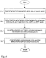
- Fig. 4 discloses the method according to the invention for setting the clearance s1 and / or s2, in particular in the case of the double clutch arrangement according to FIG Fig. 2 .
- one of the input members preferably the third input member 90, is fixed rotatably relative to the hub 46, for example on the hub shell 48.
- a second step S2 the piston / cylinder arrangement of the friction clutch is non-rotatably mounted on the hub shell 48 or the hub 46, the clearance of which is to be adjusted.
- a step S3 the desired clearance s1 and / or s2 is set by moving the associated input member 38 or 28 in the axial direction.
- the clearance s1 and / or s2 is set, the corresponding input member 38 and / or 28 is fixed on the input member that has already been fixed, preferably on the third input member 90 (cf. step S4).
Landscapes
- Engineering & Computer Science (AREA)
- General Engineering & Computer Science (AREA)
- Mechanical Engineering (AREA)
- Hydraulic Clutches, Magnetic Clutches, Fluid Clutches, And Fluid Joints (AREA)
- Structure Of Transmissions (AREA)
Description
- Die vorliegende Erfindung betrifft ein Doppelkupplungsgetriebe mit einer Doppelkupplungsanordnung, wobei ein Nabenmantel besonders ausgebildet ist. Die vorliegende Erfindung betrifft ferner eine Doppelkupplungsanordnung für ein Doppelkupplungsgetriebe, bei der Eingangsglieder von Reibkupplungen besonders ausgebildet und angeordnet sind. Des Weiteren betrifft die vorliegende Erfindung ein Verfahren zum Einstellen eines Lüftspiels von Doppelkupplungsanordnungen in derartigen Doppelkupplungsgetrieben.
- Ein Doppelkupplungsgetriebe gemäß dem Oberbegriff des Anspruchs 1 ist aus dem Dokument
US 6,378,675 B1 bekannt. - Eine Doppelkupplungsanordnung mit gehäusefesten Kolben/Zylinderanordnungen ist aus dem Dokument
DE 10 2004 061 020 A1 bekannt. - Doppelkupplungsgetriebe weisen eine Doppelkupplungsanordnung sowie zwei Teilgetriebe auf. Die Teilgetriebe sind in der Regel in Vorgelegebauweise ausgeführt. Eines der Teilgetriebe ist dabei geraden Gangstufen zugeordnet, das andere Teilgetriebe ist ungeraden Gangstufen zugeordnet.
- Durch überschneidende Betätigung der zwei Kupplungen der Doppelkupplungsanordnung kann ein Gangwechsel ohne Zugkraftunterbrechung durchgeführt werden.
- Diese Art von Doppelkupplungsgetriebe eignet sich für Kraftfahrzeuge, insbesondere für Personenkraftwagen.
- Bei den Doppelkupplungsanordnungen werden heutzutage in der Regel fluidisch betriebene (nasse) Reibkupplungen verwendet, beispielsweise nasslaufende Lamellenkupplungen.
- Aus dem Dokument
DE 10 2004 013 265 A1 ist eine Doppelkupplungsanordnung bekannt, bei der den zwei Reibkupplungen jeweils ein mitlaufender Betätigungskolben zugeordnet ist, und wobei die Betätigungskolben eine einen Druckbeaufschlagbaren Kolbenraum zugewandte erste radiale Wirkfläche und eine einem Fliehkraftdruckausgleichsraum zugewandte zweite radiale Wirkfläche aufweisen. Die Zufuhr von Fluid zu den Kolbenräumen erfolgt über eine mitdrehende Nabe und eine zwischen dieser Nabe und dem Gehäuse angeordneten Drehdurchführung. Nachteilig bei dieser Art von Doppelkupplungsanordnung ist die Tatsache, dass die Komplexität relativ groß ist und sich hohe Schleppmomente ergeben. - Eine vergleichbare Doppelkupplungsanordnung ist aus dem Dokument
DE 102 23 780 C1 bekannt. - Das Dokument
EP 1 568 906 A1 offenbarte eine Doppelkupplung mit zwei um eine gemeinsame Drehachse drehbar und axial hintereinander angeordneten Kupplungen. Die Kupplungen weisen einen gemeinsamen angetriebenen Außenlamellenträger und jeweils einen abtreibenden Innenlamellenträger auf. Es ist eine den Außenlamellenträger umgreifende Zughülse vorgesehen, über die eine der beiden Kupplungen betätigbar ist. - Ferner offenbart das Dokument
DE 10 2004 055 361 A1 eine Doppelkupplungsanordnung mit zwei radial ineinander geschachtelten Reibkupplungen, die jeweils fluidisch betätigbar sind. Jeder Kupplung ist ein Fliehkraftausgleichsraum zugeordnet, die über eine gemeinsame Leitung mit einer Ventilanordnung verbunden sind. - Aus der eingangs genannten
DE 10 2004 061 020 A1 ist bekannt, an einer gehäusefesten Nabe bei radial hintereinander verschachtelten, in die gleiche Richtung wirkenden Kolben/Zylinderanordnungen gehäusefest vorzusehen. Die Kolben/Zylinderanordnungen wirken über Hebelanordnungen auf die ebenfalls radial in einander geschachtelten Reibkupplungen der Doppelkupplungsanordnung. Ein Eingangsglied der radial äußeren Reibkupplung ist an einem Abschnitt der ersten Ausgangswelle (innere Ausgangswelle) drehbar gelagert, der sich in Richtung hin zu der Kolbenwelle erstreckt. - Insbesondere bei mitrotierenden Kolben/Zylinderanordnungen, die drehfest an einem Nabenmantel, d.h. nabenmantelfest, montiert sind, der wiederum drehbar gegenüber einer gehäusefesten Nabe gelagert ist, wird der Nabenmantel üblicherweise aus Stahl, zum Beispiel spanend, aus Vollmaterial herausgearbeitet. Stahl ist teuer. Die Bearbeitung ist aufwändig, zeit- und kostenintensiv. Das Gewicht des Stahlnabenmantels ist relativ groß, so dass bereits am Nabenmantel Schleppmomente auftreten können.
- Des Weiteren ist die Einstellung des Lüftspiels (Abstand Kupplungsaktuator zu Kupplungskörper im geöffneten Zustand) ein zeitaufwändiges Unterfangen, da das Lüftspiel für jede Kupplungsanordnung bzw. für jede der Reibkupplungen individuell gemessen und eingestellt werden muss. Insbesondere bei der Verwendung von Lamellenkupplungen als Reibkupplung ist dies schwierig. Der Lamellenkupplungskörper besteht im Wesentlichen aus zwei Lamellenkämmen, die miteinander kämmen. Je nach Ausgestaltung und Anordnung der Lamellenträger variiert der Abstand zwischen Kupplungskörper und Kupplungsaktuator mehr oder weniger stark. Dieses Lüftspiel muss individuell eingestellt werden.
- Im Stand der Technik ist es bekannt, ein oder mehrere zusätzliche (Lamellen-)Abschlussglieder einzusetzen, sollte sich nach einer Messung des Lüftspiels herausstellen, dass das Spiel zu groß ist. Dazu gibt es unterschiedlich dicke Lamellen. Einige Kupplungshersteller verwenden Baukastensysteme, die zum Beispiel acht verschiedene Lamellendicken aufweisen. Ein zwischen dem Kupplungsaktuator und einem Sicherungsring am Lamellenträger zur Verfügung stehende Raum wird vermessen. Anschließend wird errechnet, aus welchem Lamellentyp der Kupplungskörper aufzubauen ist. Anschließend wird der Lamellenkörper zusammengebaut und eingesetzt. Auch diese Vorgehensweise ist zeitaufwändig und für jede Kupplung erneut durchzuführen. Das Bauteilsortiment ist groß, da viele unterschiedliche Lamellentypen vorgehalten werden müssen.
- Das Dokument
DE 103 33 437 A1 offenbart ein Mehrstufen-Automatengetriebe mit drei Planetenradsätzen. Ein Mehrstufen-Automatengetriebe weist eine Antriebswelle, eine Abtriebswelle, drei nebeneinander in Reihe angeordnete Einzel-Planetenradsätze sowie fünf Schaltelemente auf. Ein Sonnenrad des dritten Radsatzes ist über das erste Schaltelement an einem Getriebegehäuse festsetzbar. Die Antriebswelle ist mit einem Sonnenrad des zweiten Radsatzes verbunden und über das zweite Schaltelement mit einem Sonnenrad des ersten Radsatzes und/oder über das fünfte Schaltelement mit einem Steg des ersten Radsatzes verbindbar. Alternativ ist das Sonnenrad des ersten Radsatzes über das dritte Schaltelement und/oder der Steg des ersten Radsatzes über das vierte Schaltelement an dem Getriebegehäuse festsetzbar. Die Abtriebswelle ist mit einem Hohlrad des ersten Radsatzes und einem der Stege des zweiten oder dritten Radsatzes verbunden. Das zweite und fünfte Schaltelement bilden eine Baugruppe mit je einem Lamellenpaket und je einer Servoeinrichtung, sowie einem für beide Schaltelemente gemeinsamen Lamellenträger. Das Lamellenpaket des zweiten Schaltelementes weist einen größeren Durchmesser auf als das Lamellenpaket des fünften Schaltelements. - Es ist vor dem obigen Hintergrund die Aufgabe der vorliegenden Erfindung, eine verbesserte Doppelkupplungsanordnung für ein Doppelkupplungsgetriebe anzugeben.
- Diese Aufgabe wird durch Anspruch 1 gelöst.
- Im Gegensatz zur herkömmlichen spanenden Herstellung des Nabenmantels aus einem Vollmaterial, vorzugsweise aus Stahl, wird das Nabenmantelmaterial gemäß der vorliegenden Erfindung lediglich umgeformt, nämlich mittels Blech durch Tiefziehen. Massenträgheitsmomente werden wesentlich reduziert, da der Nabenmantel vorzugsweise eine konstante Materialdicke und insbesondere eine Zylinderform aufweist. Der Nabenmantel kann deshalb kostengünstig und gewichtsoptimierter hergestellt werden.
- Gemäß der Erfindung ist der Nabenmantel ein umgeformtes Blechbauteil, vorzugsweise in einer im Wesentlichen konstanten Materialstärke von 3 mm.
- Das Gewicht ist bedeutend geringer als bei einem herkömmlichen, aus Stahl gefertigten Nabenmantel. Da die Materialstärke im Wesentlichen konstant ist, ist der Nabenmantel größtenteils zylindrisch ausgebildet. Dabei ist die Massenverteilung derart günstig, dass sich negativ auswirkende Massenträgheitsmomente, die insbesondere durch radial relativ weit außen liegende Masse hervorgerufen werden, (nahezu) vollständig eliminiert werden.
- Der Nabenmantel weist einen ersten zylindrischen Axialabschnitt mit im Wesentlichen konstantem Innen- und Außenradius aufweist, wobei die Kolben/Zylinderanordnungen außen am ersten Axialabschnitt drehfest angebracht sind.
- Ein zylindrischer Körper ist durch Umformen einfach herzustellen. Die auf den Nabenmantel zu montierenden Bauteile weisen alle den gleichen Durchgangsöffnungsdurchmesser auf, so dass Kupplungshersteller verschiedene Doppelkupplungstypen mit ein und denselben Bauteilen konstruieren können. Die Bauteilvielfalt bleibt überschaubar, und eine Baukastenteildiversität ist soweit wie möglich begrenzt.
- Der Nabenmantel weist einen zweiten Axialabschnitt mit im Wesentlichen konstantem Innen- und Außenradius auf, der sich an den ersten Axialabschnitt anschließt, der innen mittels eines Radiallagers drehbar an der Nabe gelagert ist und der außen vorzugsweise eine umlaufende Pumpenverzahnung aufweist, die aufrolliert oder aufgeprägt ist.
- Da auch der zweite Axialabschnitt im Wesentlichen zylindrisch ausgebildet ist, lässt sich ein derart ausgebildeter Nabenmantel einfach durch Tiefziehen herstellen.
- Aufwändige Naben(-mantel-)profile mit stark variierendem Radius über die axiale Länge betrachtet werden nicht mehr benötigt. Der zweite Axialabschnitt dient im Wesentlichen zur Aufnahme des Radiallagers, um den Nabenmantel in radialer und/oder axialer Richtung drehbar an der Nabe abzustützen.
- Gemäß einer weiteren bevorzugten Ausführungsform weisen der erste und der zweite Axialabschnitt unterschiedliche Innendurchmesser auf. Ferner kann eines der Eingangsglieder mit einem radial orientierten, zwischen dem ersten und zweiten Axialabschnitt vorgesehenen Übergangsabschnitt verbunden werden.
- Umlaufende Vertiefungen (Nuten) im Nabenmantel, die durch spanende Bearbeitung hergestellt werden müssten, sind nicht erforderlich.
- Die oben genannte Aufgabe wird ferner durch eine Doppelkupplungsanordnung für ein Doppelkupplungsgetriebe gelöst, wobei die Doppelkupplungsanordnung eine Eingangswelle, eine erste Reibkupplung, eine zweite Reibkupplung, zwei Ausgangswellen, eine gehäusefeste Nabe, eine erste Kolben/Zylinderanordnung und eine zweite Kolben/Zylinderanordnung aufweist. Eingangsglieder der Reibkupplungen sind an die Eingangswelle gekoppelt. Ausgangsglieder der Reibkupplungen sind jeweils mit einer der Ausgangswellen verbunden. Die Reibkupplungen sind jeweils mittels einer der Kolben/Zylinderanordnungen betätigbar. Ferner ist ein drehbar an der Nabe gelagerter Nabenmantel vorgesehen. Außerdem sind mindestens ein erstes, ein zweites und ein drittes Eingangsglied vorgesehen, wobei das erste Eingangsglied ein Innenglied der radial außen liegenden Reibkupplung trägt. Das zweite Eingangsglied ist drehfest an das erste Eingangsglied gekoppelt und trägt ein Innenglied der radial innen liegenden Reibkupplung. Das dritte Eingangsglied ist an seinem einen Ende an die Nabe und an seinem anderen Ende eben mit dem zweiten Eingangsglied und außen mit dem ersten Eingangsglied drehfest verbunden.
- Mit einer derartig aufgebauten Doppelkupplungsanordnung lassen sich das Lüftspiel sowohl der ersten als auch der zweiten Reibkupplung auf einfache Weise beim Zusammenbau der Doppelkupplung einstellen und festlegen. Insbesondere sind dazu keine weiteren Elemente erforderlich, wie es zum Beispiel durch die zusätzlichen Endlamellen im Falle einer Lamellenkupplung der Fall ist. Es müssen also keine zusätzlichen Lamellen(-Typen) vorgesehen werden, um das Lüftspiel einzustellen.
- Ferner ist es bevorzugt, dass die Reibkupplungen Lamellenkupplungen sind.
- Außerdem hat es sich als vorteilhaft herausgestellt, dass das erste und das zweite Eingangsglied jeweils derart ausgebildet sind, dass sie ein Gegenlager beim Betätigen der ihnen zugeordneten Reibkupplungen bilden.
- Die Ausgestaltung der Eingangsglieder mit integriertem Gegenlager macht das Vorsehen von Gegenlagerringen an den Eingangsgliedern überflüssig. Die Gegenlagerringe mussten herkömmlicherweise am Eingangsglied montiert werden, nachdem das Lüftspiel gemessen war. All diese Arbeitsschritte entfallen jetzt.
- Bei einer weiteren besonderen Ausgestaltung weist das Eingangsglied der äußeren Reibkupplung eine Außenverzahnung zum Einstecken in eine Innenverzahnung der Eingangswelle auf, wobei die Eingangswelle vorzugsweise außen ein Radiallager und eine Wellendichtung trägt.
- Im eingangsseitigen Bereich der Doppelkupplung kann so in radialer Richtung Bauraum eingespart werden.
- Ferner wird die obige Aufgabe durch ein Verfahren zum Einstellen eines Lüftspiels in einer Doppelkupplungsanordnung gemäß einem der vorhergehenden Ansprüche gelöst, wobei das einer jeweiligen der Reibkupplungen zugeordnete Eingangsglied derart ausgebildet ist, dass es ein Gegenlager für die zugeordnete Reibkupplung bildet. Das Verfahren weist die folgenden Schritte auf: Fixieren eines der Eingangsglieder relativ zur Nabe; drehfestes Montieren der Kolben/Zylinderanordnung an der Nabe oder am Nabenmantel; Einstellen eines gewünschten Kupplungsspiels durch axiales Bewegen des Eingangsglieds an dem Eingangsglied, welches relativ zur Nabe fixiert wurde, wenn das gewünschte Spiel eingestellt ist.
- Anstatt auf aufwändige Weise, wie im Stand der Technik üblich, zusätzliche Lamellenglieder in den Kupplungskörper einzubauen, um das Lüftspiel zu korrigieren, lässt sich das Lüftspiel gemäß der vorliegenden Erfindung durch einfaches axiales Bewegen des Eingangsglieds ändern, dessen Lüftspiel eingestellt werden soll. Anschließend wird dieses Eingangsglied fixiert und die (Vor-)Montage der Doppelkupplungsanordnung wird fortgesetzt.
- Die Doppelkupplungsanordnung wird also wie üblich schrittweise radial von innen nach außen aufgebaut. Das Eingangsglied, das mit der Reibkupplung verbunden ist, deren Lüftspiel eingestellt werden soll, wird wie beim normalen Aufbau üblich, einfach an der dafür vorgesehenen Stelle fixiert, wobei zur Variation des Lüftspiels dessen Eingangsglied in axialer Richtung vorher bewegt wird. Das Messen des Lüftspiels und das axiale Bewegen kann simultan erfolgen, so dass beim Aufbau der Doppelkupplung nahezu keine Zeit für das Einstellen des Lüftspiels verloren geht. Weniger Bauteil müssen vorgehalten werden. Die zusätzlichen Lamellen entfallen beispielsweise.
- Gemäß einer besonderen Ausgestaltung werden insbesondere die folgenden Schritte durchgeführt: Fixieren des dritten Eingangsglieds relativ zur Nabe; Montieren der Kolben/Zylinderanordnung, die der außen liegenden Reibkupplung zugeordnet ist; Einbauen des zweiten Eingangsglieds mit zugeordnetem Reibkupplungskörper; Montieren der Kolben/Zylinderanordnung , die der innen liegenden Reibkupplung zugeordnet ist; wahlweises Einstellen des Kupplungsspiels der inneren Reibkupplung durch axiales Verschieben des zweiten Eingangsglieds; Fixieren des zweiten Eingangsglieds am dritten Eingangsglied; Einbauen des Ausgangsglieds der inneren Reibkupplung; Einbauen des Ausgangsglieds der äußeren Reibkupplung inklusive des Reibkupplungskörpers der äußeren Reibkupplung; wahlweises Einstellen des Kupplungsspiels der äußeren Reibkupplung durch axiales Verschieben des dritten Eingangsglieds; und Fixieren des ersten Eingangsglieds am dritten Eingangsglied.
- Durch das Vorsehen von drei Eingangsgliedern, von denen die zwei, direkt den Reibkupplungen zugeordnete Eingangsglieder Abschnitte aufweisen, die als Gegenlager für den Kupplungskörper ausgebildet sind, können beide oder auch nur eines der Lüftspiele beim Aufbau der Doppelkupplungsanordnung auf einfache Weise und schnell eingestellt werden. Der Aufbau bzw. Zusammenbau der Doppelkupplung kann simultan zum Messen des Lüftspiels erfolgen, so dass man sich viel Zeit beim Zusammenbauen der Doppelkupplung sparen kann.
- Es versteht sich, dass die vorstehend genannten und die nachstehend noch zu erläuternden Merkmale nicht nur in der jeweils angegebenen Kombination, sondern auch in anderen Kombinationen oder in Alleinstellung verwendbar sind, ohne den Rahmen der vorliegenden Erfindung zu verlassen.
- Ausführungsbeispiele der Erfindung sind in der Zeichnung dargestellt und werden in der nachfolgenden Beschreibung näher erläutert. Es zeigen:
- Fig. 1
- eine teilweise geschnittene Seitenansicht auf eine Doppelkupplungsanordnung mit einem Nabenmantel gemäß der vorliegenden Erfindung;
- Fig. 2
- eine Doppelkupplungsanordnung ähnlich der
Fig. 1 , wobei das Eingangsglied mehrteilig zum Einstellen des Lüftspiels gemäß der vorliegenden Erfindung aufgebaut ist; - Fig. 3
- eine Detailansicht einer Verbindung zwischen einer Eingangswelle und einem ersten Eingangsglied; und
- Fig. 4
- ein Flussdiagramm des Verfahrens gemäß der vorliegenden Erfindung.
- In der nachfolgenden Beschreibung der Figuren werden ähnliche Merkmale mit den gleichen Bezugszeichen versehen. Sollten gravierende Unterschiede zwischen einzelnen Merkmalen vorhanden sein, wird explizit hingewiesen werden.
- Ein Antriebsstrang 10 mit einem Antriebsmotor 12 (vg.
Fig. 2 ), wie zum Beispiel ein Verbrennungsmotor, ist explizit in derFig. 1 nicht gezeigt, aber trotzdem als vorhanden anzusehen. Der Antriebsstrang 10 weist ferner ein Doppelkupplungsgetriebe 14 auf, dessen Eingang mit einer Kurbelwelle 16 (vgl.Fig. 2 ) des Verbrennungsmotors 12 verbunden ist. Das Doppelkupplungsgetriebe 14 weist eine Abtriebswelle 18 auf, die in an sich bekannter Weise mit Antriebsrädern des Fahrzeugs verbunden werden kann. - Das Doppelkupplungsgetriebe 14 weist eine Doppelkupplungsanordnung 20 auf, die in einem Gehäuse aufgenommen ist. In
Fig. 1 ist lediglich ein Kupplungsdeckel 22 als Teil des Gehäuses gezeigt. - Die Doppelkupplungsanordnung 20 beinhaltet eine erste Reibkupplung 24 und eine zweite Reibkupplung 26. Die zwei Reibkupplungen 24, 26 sind radial ineinander verschachtelt angeordnet, wobei die erste Reibkupplung 24 radial außen liegt.
- Die erste Reibkupplung 24 weist ein erstes Eingangsglied 28 auf, das an den Eingang, d.h. an die Kurbelwelle 16, gekoppelt ist. Dazu ist das erste Eingangsglied 28 drehfest mit einer Mitnehmerscheibe 29 verbunden. Die Mitnehmerscheibe 29, die sich im Wesentlichen in radialer Richtung erstreckt, weist in axialer Richtung einen Mitnehmervorsprung bzw. -ring 17 mit einer Innenverzahnung 17' auf. Mit Hilfe der Innenverzahnung 17' kann die Mitnehmerscheibe 29 an die Kurbelwelle 16 (in
Fig. 1 nicht dargestellt) koppeln, die wiederum eine hier nicht dargestellte Außenverzahnung aufweist. Die axiale Länge des Rings 17 ist so gewählt, dass das Wellendichtlager 98 und das Radiallager 59 (bzw. 96 inFig. 2 ) außenseitig am Ring 17 angebracht werden können, wobei die Länge der Innenverzahnung entsprechend gewählt ist. Der Ring 17 baut viel kürzer als im Stand der Technik. - Das erste Eingangsglied 28 erstreckt sich nach Art eines Korbes axial. Die zwei Reibkupplungen 24, 26 sind radial innerhalb des ersten Eingangsglieds 28 angeordnet.
- Die erste Reibkupplung 24 weist ferner ein erstes Ausgangsglied 30 auf. Das erste Ausgangsglied 30 ist mit einer ersten Ausgangswelle 32 der Doppelkupplungsanordnung verbunden. Die Ausgangswelle 32 ist als Vollwelle ausgebildet und ist mit einem ersten Teilgetriebe 34 (vgl. auch
Fig. 2 ) des Doppelkupplungsgetriebes 14 verbunden. - Das erste Ausgangsglied 30 ist ebenfalls nach der Art eines Korbs ausgebildet und erstreckt sich radial innerhalb des ersten Eingangsglieds 28, wobei die erste Reibkupplung 24 dazwischen aufgenommen ist.
- Die zweite Reibkupplung 26 weist ein zweites Eingangsglied 38 auf. Das zweite Eingangsglied 38 ist drehfest mit dem ersten Eingangsglied 28 verbunden, wie es hier durch eine dreieckig dargestellte Schweißverbindung 39 exemplarisch gezeigt ist. Die zweite Reibkupplung 26 weist ferner ein zweites Ausgangsglied 40 auf. Das zweite Ausgangsglied ist ebenfalls nach Art eines Korbes ausgebildet und erstreckt sich radial innerhalb des ersten Ausgangsglieds 30. Das zweite Ausgangsglied 40 ist mit einer zweiten Ausgangswelle 42 verbunden, die als Hohlwelle konzentrisch zu der ersten Ausgangswelle 32 angeordnet ist. Die zweite Ausgangswelle 42 ist mit einem zweiten Teilgetriebe 44 (vgl.
Fig. 2 ) des Doppelkupplungsgetriebes 14 verbunden. Das erste Eingangsglied 28 inklusive der Mitnehmerscheibe 29, das erste Ausgangsglied 30 und das zweite Ausgangsglied 40 erstrecken sich, wie oben erwähnt, nach der Art von Körben ausgehend von dem Bereich der Kurbelwelle 16 in Richtung hin zu den Teilgetrieben 34, 44 bzw. zur Abtriebswelle 18. Zum anderen weist die Doppelkupplungsanordnung 20 eine gehäusefeste Nabe 46 auf, die sich in axialer Richtung von dem Bereich der Teilgetriebe 34, 44 in Richtung hin zu dem Bereich der Kurbelwelle 16 erstreckt. Die Nabe 46 weist im Bereich der Doppelkupplungsanordnung 20 eine im Wesentlichen zylindrische Form auf. Die gehäusefeste Nabe 46 ist dabei koaxial zu den zwei Ausgangswellen 32, 42 angeordnet und umgibt diese hier. - Zwischen einer Stirnseite der gehäusefesten Nabe 46 und radialen Abschnitten der Ausgangsglieder 30, 40 und einem radialen Abschnitt der Mitnehmerscheibe 29 sind hier nicht näher bezeichnete Axiallager vorgesehen. Diese Axiallager sind in radialer Richtung mit einem drehbar zur Nabe 46 gelagerten Nabenmantel 48 ausgerichtet.
- Der Nabenmantel 48 ist im Bereich der Doppelkupplungsanordnung 14 zylindrisch ausgebildet und koaxial zu den Ausgangswellen 32, 42 angeordnet.
- Der Nabenmantel 48 ist hier aus vorzugsweise aus 3 - 5 mm starkem Blech geformt. Im Stand der Technik werden Nabenmäntel aus Stahl mit spanender Bearbeitung hergestellt, wobei die herkömmlichen Nabenmäntel von einem gleichförmigen Zylinderquerschnitt abweichende Querschnitte (mit variierendem Radius) aufweisen, um unterschiedlichste Kupplungselemente (z.B. Lager, Aktuatoren, usw.) bei unterschiedlichen radialen Abständen aufnehmen zu können. Der Nabenmantel 48 gemäß der vorliegenden Erfindung weist - zumindest im Bereich der Doppelkupplungsanordnung 14, die im Wesentlichen vom Eingangsglied 28 und der Mitnehmerscheibe 29 umschlossen wird - einen konstanten Innenradius Ri und einen konstanten Außenradius Ra auf.
- Der Nabenmantel 48 kann ferner eine, vorzugsweise einstückig ausgebildete, Verzahnung 50 an seinem der Abtriebswelle 18 gegenüberliegenden Ende aufweisen. Diese Verzahnung 50 kann mit einer entsprechenden Verzahnung z.B. einer hier nicht dargestellten Hydraulikpumpe 50 kämmen, um Fluide, die zum Betätigen und/oder Schmieren der Doppelkupplungsanordnung 14 benötigt werden, durch einzelne Öffnung 52 im Nabenmantel 48 zu führen. Die Öffnungen 52, von denen in der
Fig. 1 drei gezeigt sind, können zum Beispiel gebohrt oder gestanzt werden. Die Öffnungen 52 stehen fluidmäßig mit einem zentralen Kanal 54 und umlaufend vorgesehenen Nuten in der Nabe 46 in Verbindung. Das Fluid wird durch die Nabe 46 in die Doppelkupplungsanordnung 14 durch die Öffnungen 52 geleitet. Die Öffnungen 52 befinden sich hier in einem ersten Axialabschnitt 55 des Nabenmantels 48, an dem eine Vielzahl der relevanten Elemente der Doppelkupplungsanordnung 14 bei gleichbleibendem (Nabenmantel-)Radius montiert sind. An den ersten Axialabschnitt 55 schließt sich ein zweiter Axialabschnitt 56 auf. Der zweite Axialabschnitt 56 ist über einen Radialabschnitt 57 mit dem ersten Axialabschnitt 55 verbunden. Der Radius des zweiten Axialabschnitts 56 ist hier größer als der Radius des ersten Axialabschnitts 55, um ein Radiallager 58 zwischen dem Nabenmantel 48 und der Nabe 46 aufnehmen zu können. Die Komponenten 590, 55 -57 sind hier einstückig ausgebildet. Die Pumpenverzahnung kann aufrolliert bzw. aufgeprägt werden. - Mit Hilfe des Radiallagers 58 stützt sich die Doppelkupplungsanordnung 14 im Wesentlichen an der Nabe 46 ab. Ein zweites Radiallager 59 ist auf der gegenüberliegenden Seite im Bereich des gehäusefesten Kupplungsdeckels 22 angeordnet. Auf diese Weise können eine Vielzahl der Elemente der Doppelkupplungsanordnung 20 rotierend um die Nabe 46 gehalten werden.
- Das erste Eingangsglied 28 ist an seinem der Eingangswelle 16 abgewandten Seite hier ebenfalls mittels einer exemplarischen Schweißverbindung mit dem Radialabschnitt 57 des Nabenmantels 48 (axial) verbunden. Alternativ und ergänzend könnte das erste Eingangsglied 28 aber auch mit dem ersten Axialabschnitt 55 verbunden sein.
- Es versteht sich, dass der Nabenmantel 48 auch einen konstanten, einzigen Radius (Ri und Ra) aufweisen könnte, so dass die Axialabschnitte 55, 56 eins wären, d.h. ohne den Radialabschnitt 57 vorgesehen wären. Das Radiallager 58 könnte dazu in einer entsprechend ausgebildeten Ausnehmung in der Nabe 46 vorgesehen werden.
- Ein großer Vorteil des Nabenmantels 48 ist, dass er aus einem relativ kostengünstigen Blechmaterial, z.B. 3 mm starken Blech, mittels Umformvorgängen hergestellt werden kann. Da der Nabenmantel 48 einen nahezu konstanten Radius aufweist, können viele gleiche Bauteile, insbesondere mit gleichen Durchgangsöffnungsradien verwendet werden. Derartige Teile werden nachfolgend erläutert.
- Zur Lagerung des zweiten Eingangsglieds 38, und damit mittelbar auch des ersten Eingangsglieds 28, ist das Radiallager 58 vorgesehen. Obgleich das Radiallager 58 im Wesentlichen Radialkräfte aufnimmt, kann es auch zur Aufnahme von Axialkräften ausgelegt sein.
- Zum Betätigen der zwei Reibkupplungen 24, 26 sind eine erste Kolben/Zylinderanordnung 60 und eine zweite Kolben/Zylinderanordnung 62 vorgesehen. Die Kolben/Zylinderanordnungen 60, 62 sind auf sich gegenüberliegenden Seiten bei einem gleichen Radius (relativ zur gemeinsamen Drehachse des Gesamtsystems) angeordnet.
- Die erste Kolben/Zylinderanordnung 60 weist einen ersten Kolben 64 auf, der in axialer Richtung in dem ersten Zylinder 66 verschieblich gelagert ist. Ein hierdurch gebildeter Zylinderraum ist über eine der Radialöffnungen 52 im Nabenmantel 48 mit der Zuführleitung 54 innerhalb der gehäusefesten Nabe 46 verbunden.
- Die Außenseite des ersten Kolbens 64 ist an eine erste Druckplatte 68 gekoppelt. Die erste Druckplatte 68 erstreckt sich radial nach außen und weist axiale Abschnitte auf. Ein radial außen liegender Axialabschnitt der Druckplatte 68 ist dazu ausgelegt, die erste Reibkupplung 24 axial mit einer Kraft (vgl. Pfeil 69) zu beaufschlagen, um die Reibkupplung 24 zu schließen, die in der
Fig. 1 in einem geöffneten Zustand gezeigt ist. - Die erste Druckplatte 68 dreht sich mit dem ersten und dem zweiten Eingangsglied 28, 38 mit. Die Druckplatte 68 dreht sich auch mit dem nabenmantelfesten Kolben 64 bzw. dem nabenmantelfesten Zylinder 66 mit.
- Der obere Axialabschnitt der ersten Druckplatte 68, der an Lamellen der ersten Reibkupplung 24 anstoßen kann, erstreckt sich durch eine hier nicht näher gezeigte Öffnung in einem Radialabschnitt des zweiten Eingangsglieds 38 hindurch. Bei einem konstruktiv realisierten Ausführungsbeispiel wird in der Regel eine Mehrzahl solcher Öffnungen vorgesehen sein, die über den Umfang der ersten Druckplatte 68 verteilt angeordnet sind.
- Auf einer der ersten Kolben/Zylinderanordnung 60 gegenüberliegenden Seite ist ein T-förmiges Drehglied 70 mit innerem Kanal 72 zur Versorgung mit Fluid vorgesehen. Zwischen dem Kolben 64 und der linken Seite des Drehglieds 70 ist eine erste Federanordnung 74 vorgesehen, um die erste Druckplatte 68 in eine geöffnete Stellung vorzuspannen. Die erste Federanordnung 74 stützt sich dazu an einem Radialsteg des Drehglieds 70 ab und drückt den Kolben 64, und damit auch die erste Druckplatte 68, in axialer Richtung von dem Radialabschnitt weg, hin in Richtung zu den hier nicht dargestellten Teilgetrieben 34, 44 (vgl.
Fig. 2 ). Zum Betätigen der ersten Reibkupplung 24 wird der ersten Kolben/Zylinderanordnung 60 Hydraulikfluid zugeführt, so dass der erste Kolben 64 in die entgegengesetzte Richtung bewegt wird und folglich über die erste Druckplatte 68 eine Axialkraft auf das Lamellenpaket der ersten Reibkupplung 24 ausübt. - Die zweite Kolben/Zylinderanordnung 62 ist in entsprechender Weise, vorzugsweise aus gleichen Bauteilen, etwa spiegelbildlich hierzu aufgebaut. Die erste und die zweite Kolben/Zylinderanordnung 60, 62 können folglich mit ähnlichen oder identischen Bauteilen realisiert werden, insbesondere mit gleichem Durchgangsöffnungsradius, so dass sich eine hohe Modularität und eine geringe Vielfalt ergibt.
- Die zweite Kolben/Zylinderanordnung 62 weist demzufolge einen zweiten Zylinder 78 auf, der drehfest mit dem Nabenmantel 46 verbunden ist, und zwar im Wesentlichen benachbart zu dem zweiten Ausgangsglied 40.
- Die zweite Kolben/Zylinderanordnung 82 weist ferner einen zweiten Kolben 76 auf, der auf eine zweite Druckplatte 80 wirkt. Ein radialer Abschnitt der zweiten Druckplatte 80 liegt an einem Lamellenpaket der zweiten, radial innen liegenden Reibkupplung 26 an. Die zweite Kolben/Zylinderanordnung 62 kann folglich eine zweite Axialkraft (vgl. Pfeil 82) auf die zweite Reibkupplung 26 ausüben, wobei die zweite Axialkraft entgegengesetzt zu der ersten Axialkraft ausgerichtet ist.
- Zwischen einem weiteren Radialabschnitt des Drehglieds 70 und dem Kolben 78 der zweiten Kolben/Zylinderanordnung 62 ist eine zweite Federanordnung 84 vorgesehen, die den Kolben 78, und somit auch die zweite Druckplatte 80, hin zur Eingangswelle 16 vorspannt.
- Der Zylinderraum der zweiten Kolben/Zylinderanordnung 62 ist über die Radialöffnung 52 (ganz rechts) im Nabenmantel 48 mit dem Kanal 54 in der Nabe 46 verbunden. Es versteht sich, dass eine hier nicht näher dargestellte Hydraulikschaltung auch Kanäle aufweist, über die den Reibkupplungen 24, 26 Kühlfluid zugeführt werden kann.
- Das Kühlfluid wird dabei über Kanäle in der gehäusefesten Nabe 46, u.A. einem Raum im Bereich des Drehglieds 70 und den Radialkanäle 72 im Drehglied 70 und den Reibkupplungen 24, 26 zugeführt. Es versteht sich, dass in den Eingangs- und Ausgangsgliedern 38, 30, 40 jeweils geeignete Radialöffnungen vorgesehen sind, um für eine geeignete Beströmung der Lamellen zu sorgen.
- Während in
Fig. 1 die Reibkupplungen 24, 26 als nasslaufende Lamellenkupplungen dargestellt sind, versteht es sich, dass der Aufbau der erfindungsgemäßen Doppelkupplungsanordnung 20 auch für trockenlaufende Reibkupplungen verwendbar ist. In diesem Fall könnte beispielsweise über Kanäle, die bei nasslaufenden Kupplungen zur Kühlölzufuhr verwendet werden, Kühlluft zugeführt werden. - Insgesamt lässt sich somit ein modulares System von Doppelkupplungsanordnungen aufbauen, die mit nasslaufenden oder trockenlaufenden Reibkupplungen ausgestattet sind. Der grundlegende Aufbau kann dabei für die eine wie die andere Variante verwendet werden.
- Bezugnehmend auf
Fig. 2 ist eine weitere Doppelkupplungsanordnung 20 gezeigt, die eine separate Erfindung widerspiegelt. In derFig. 2 sind auch der Verbrennungsmotor 12, die Eingangswelle (Kurbelwelle) 16 sowie die Teilgetriebe 34, 44 gezeigt. - Mit Ausnahme der Eingangsglieder ist die Doppelkupplungsanordnung 20 der
Fig. 1 identisch zur Doppelkupplungsanordnung derFig. 1 aufgebaut. - Bei der Doppelkupplungsanordnung 20 gemäß
Fig. 2 sind drei Eingangsglieder 28, 38 und 90 vorgesehen. - Das erste Eingangsglied 28 ist hier durchgehend ausgebildet, so dass auf die Mitnehmerscheibe 29 der
Fig. 1 verzichtet werden kann. Das erste Eingangsglied 28 ist mittels einer exemplarischen Schweißverbindung 39' mit dem dritten Eingangsglied 90 verbunden, das wiederum über eine exemplarische Schweißverbindung mit dem Gehäusemantel 48 verbunden ist. Das dritte Eingangsglied 90 ist ferner mittels einer exemplarischen Schweißverbindung 39 mit dem zweiten Eingangsglied 38 verbunden. - Sowohl das erste Eingangsglied 28 als auch das zweite Eingangsglied 38 weisen im Bereich der Lamellenkupplungspakete knieförmige Ausbuchtungen in Richtung der Kupplungskörper auf. Diese knieförmigen Ausbuchtungen dienen als Gegenlager 92 bzw. 94 beim Betätigen der ersten Reibkupplung 24 bzw. der zweiten Reibkupplung 26. Halteringe oder ähnliches, wie sie aus dem Stand der Technik bekannt sind, sind zum Fixieren der Reibkupplungskörper am Lamellenträger nicht erforderlich.
- Zwischen dem Kupplungskörper der zweiten Reibkupplung 26 und der zweiten Druckplatte 80 ist ein Lüftspiel s1 definiert. Zwischen dem Kupplungskörper der ersten, radial außenliegenden Reibkupplung 26 und der ersten Druckplatte 68 ist ein weiteres Lüftspiel s2 definiert. Mit Hilfe der Lüftspiele s1, s2 lässt sich die Kraft (vgl. Pfeile 69, 82) einstellen, mit der die Reibkupplungen 24, 26 geschlossen werden. Das Einstellen dieser Kräfte erfordert im Stand der Technik eine Individualvermessung der daran beteiligten Komponenten.
- Indem bei der vorliegende Erfindung drei Eingangsglieder 28, 38, 90 vorgesehen werden, lässt sich bei der Montage der Doppelkupplungsanordnung 20 selbst das Lüftspiel s1, s2 jeder Reibkupplung 24, 26 auf einfache Weise einstellen, wie es auch im Zusammenhang mit dem Flussdiagramm der
Fig. 4 noch näher erläutert werden wird. Die Doppelkupplungsanordnung 20 wird von radial innen in axialer Richtung (von links nach rechts inFig. 2 ) radial nach außen (nach oben inFig. 2 ) (vor-)montiert. - Als erstes der Eingangsglieder wird das dritte Eingangsglied 90 am Nabenmantel 48 fixiert. Dieses dritte Eingangsglied 90 dient als Referenzglied für die beiden anderen Eingangsglieder 28 und 38.
- Nachdem das dritte Eingangsglied 90 am Mantel 48 fixiert ist, wird die erste Kolben/Zylinderanordnung 60 nabenmantelfest montiert. Anschließend wird die erste Druckplatte 68 eingebaut. Dann folgt das Drehlager 70 mit zumindest der ersten Federanordnung 74. Anschließend wird das zweite Eingangsglied 38 inklusive der Innenlamellen der zweiten Reibkupplung 26 eingebaut. Das zweite Eingangsglied 38 dient als Innenlamellenträger der zweiten Reibkupplung 26.
- Dann wird die zweite Federanordnung 84 und die zweite Kolben/Zylinderanordnung 62 inklusive der zweiten Druckplatte 80 eingebaut. Das zweite Eingangsglied 38 ist währenddessen in axialer Richtung noch frei gegenüber dem dritten Eingangsglied 90 beweglich, so dass das Lüftspiel s1 der zweiten Reibkupplung 26 beliebig eingestellt werden kann. Sobald das Lüftspiel s1 eingestellt ist, kann das zweite Eingangsglied 38 am dritten Eingangsglied 90 zum Beispiel mit einer Schweißverbindung 39 fixiert werden.
- Danach wird das zweite Ausgangsglied 40, das erste Ausgangsglied 30 mit den Innenlamellen der ersten Reibkupplung 24 und das erste Eingangsglied 28 mit den Außenlamellen der ersten Reibkupplung 24 montiert. Das erste Eingangsglied 28 ist zu diesem Zeitpunkt relativ zum dritten Eingangsglied 90 noch frei axial (und auch radial) beweglich. Danach wird das Lüftspiel s2 der ersten Reibkupplung 24 eingestellt. Dazu kann der Lamellenkörper der ersten Reibkupplung 24 in einem ersten Schritt in Anschlag an die erste Druckplatte 68 gebracht werden, wobei man einen Referenzpunkt am dritten Eingangsglied 90 definiert und dann das erste Eingangsglied 28 in das Lüftspiel s2 über dem dritten Eingangsglied 90 axial nach vorn (auch in Richtung des Motors 12) bewegt. Danach kann das erste Eingangsglied 28 mit dem dritten Eingangsglied 39 zum Beispiel verschweißt werden, um die Elemente gegeneinander zu fixieren.
- Vorteil dieser Vorgehensweise ist, dass man während des Montierens der Doppelkupplungsanordnung 20 selbst eines oder beide Lüftspiele s1, s2 auf einfache Weise einstellen kann, ohne weitere Lamellen einbauen zu müssen oder sonstige Vorkehrungen treffen zu müssen.
- Es versteht sich, dass die Doppelkupplungsanordnung 20 der
Fig. 2 auch mit gehäusefesten Kolben/Zylinderanordnungen 60, 62 gebaut werden könnte. Die Kolben/Zylinderanordnungen 60, 62 würden dann direkt auf der Nabe 46 montiert werden, wobei dann zusätzliche Radiallager im Bereich des Drehglieds 70 erforderlich sein können, wie es in derDE 10 2006 010 113 B4 gezeigt ist, auf die hinsichtlich des Aufbaus einer Doppelkupplungsanordnung mit drehfesten Kolben/Zylinderanordnungen Bezug genommen wird. Das dritte Eingangsglied 90 wäre dann z.B. so zu formen, dass es, in axialer Richtung vorzugsweise unveränderlich, an einem geeignet aufgebauten Radiallager anliegt. Das dritte Eingangsglied würde dann zum Beispiel grob einen S-förmigen Querschnitt aufweisen, wobei ein oberer, radial außen liegender Axialabschnitt zur Verbindung mit dem ersten Eingangsglied 28 und dem zweiten Eingangsglied 38 dient und ein hinterer, radial innen liegender Axialabschnitt mit dem entsprechend ausgebildeten Radiallager zusammenwirkt. Dieses Radiallager würde insbesondere Axialkräfte aufnehmen können. - Bezugnehmend auf
Fig. 3 ist eine Abwandlung der Ankopplung des Eingangsglieds 28 (vgl.Fig. 2 ) bzw. der Mitnehmerscheibe 29 (vgl.Fig. 1 ) an die Eingangswelle 16 gezeigt. Anstatt des Mitnehmervorsprungs 17 wird das erste Eingangsglied 28 bzw. die Mitnehmerscheibe 29 im Bereich der Eingangswelle 16 mit einer Außenverzahnung 110 versehen. Die Eingangswelle 16 weist dann eine Innenverzahnung 112 auf, die mit der Außenverzahnung 110 kämmt. Das Eingangsglied 28 bzw. die Mitnehmerscheibe 29 kann mit Hilfe einer Dichtung 114 gegenüber der Eingangswelle 16 abgedichtet werden. - Die Eingangswelle 16 trägt dann das Radiallager 59 (vgl.
Fig. 1 ) bzw. das Radiallager 69 (vgl.Fig. 2 ) sowie eine Wellendichtung 98. - Vorteil dieser Bauweise ist, dass die Doppelkupplungsanordnung 20 im Bereich der Eingangswelle 16 in radialer Richtung 116 bedeutend platzsparender als herkömmliche Lösungen baut. Ferner ist eines der Axiallager 118 gezeigt (vgl.
Fig. 1 und2 ). -
Fig. 4 offenbart das erfindungsgemäße Verfahren zum Einstellen von Lüftspielen s1 und/oder s2, insbesondere bei der Doppelkupplungsanordnung gemäßFig. 2 . - In einem ersten Schritt S1 wird eines der Eingangsglieder, vorzugsweise das dritte Eingangsglied 90, drehbar relativ zur Nabe 46, zum Beispiel am Nabenmantel 48, fixiert.
- In einem zweiten Schritt S2 wird die Kolben/Zylinderanordnung der Reibkupplung drehfest am Nabenmantel 48 oder der Nabe 46 montiert, deren Lüftspiel einzustellen ist.
- Danach wird in einem Schritt S3 das gewünschte Lüftspiel s1 und/oder s2 durch Bewegen des zugeordneten Eingangsglieds 38 bzw. 28 in axialer Richtung eingestellt. Wenn das Lüftspiel s1 und/oder s2 eingestellt ist, wird das entsprechende Eingangsglied 38 und/oder 28 am bereits fixierten Eingangsglied, vorzugsweise am dritten Eingangsglied 90, fixiert (vgl. Schritt S4).
Claims (8)
- Doppelkupplungsgetriebe (14) aufweisend eine Doppelkupplungsanordnung (20) miteiner Eingangswelle (16), einer ersten Reibkupplung (24), einer zweiten Reibkupplung (26), zwei sich axial erstreckenden Ausgangswellen (32, 42), die mit einem ersten bzw. zweiten Teilgetriebe (34, 44) des Doppelkupplungsgetriebes verbunden sind,einer gehäusefesten Nabe (46), in der ein Kanal (54) vorgesehen ist,einem drehbar auf der Nabe (46) gelagerten Nabenmantel (48), der Öffnungen (52) aufweist, die fluidmäßig mit dem Kanal (54) in Verbindung stehen, um ein Fluid durch die Nabe (46) in die Doppelkupplungsanordnung (14) durch die Öffnungen (52) zu leiten,einer ersten nabenmantelfesten Kolben/Zylinderanordnung (60) und einer zweiten nabenmantelfesten Kolben/Zylinderanordnung (62),wobei mindestens zwei Eingangsglieder (28, 38, 90) der Reibkupplungen (24, 26) an die Eingangswelle (16) gekoppelt sind,wobei Ausgangsglieder (30,40) der Reibkupplungen (24, 26) jeweils mit einer der Ausgangswellen (32, 42) verbunden sind,wobei die Reibkupplungen (24, 26) jeweils mittels einer der nabenmantelfesten Kolben/Zylinderanordnungen (60, 62) betätigbar sind,dadurch gekennzeichnet, dass der Nabenmantel (48) ein durch Tiefziehen umgeformtes Bauteil ist,wobei der Nabenmantel (48) ein umgeformtes Blechbauteil (47) ist,wobei der Nabenmantel (48) einen ersten zylindrischen Axialabschnitt (55) mit im Wesentlichen konstantem Innenradius (Ri) und Außenradius (Ra) aufweist, wobei die Kolben/Zylinderanordnungen (60, 62) außen am ersten zylindrischen Axialabschnitt (55) drehfest angebracht sind, undwobei der Nabenmantel (48) einen zweiten zylindrischen Axialabschnitt (56) mit im Wesentlichen konstantem Innen- und Außenradius aufweist, der sich an den ersten Axialabschnitt (55) anschließt, der innen mittels eines Radiallagers (58) an der Nabe (46) gelagert ist
- Doppelkupplungsgetriebe (14) nach Anspruch 1, wobei das Blechbauteil (47) eine im Wesentlichen konstanten Materialstärke von 3 mm aufweist.
- Doppelkupplungsgetriebe nach Anspruch 1, wobei der zweite zylindrische Axialabschnitt (56) außen eine umlaufende Verzahnung (50) aufweist, die aufrolliert oder aufgeprägt ist, um zum Beispiel eine Hydraulikpumpe anzutreiben.
- Doppelkupplungsgetriebe nach Anspruch 1 oder 3, wobei eines der Eingangsglieder (28, 38) der Reibkupplungen (24, 26) mit dem ersten und/oder dem zweiten Axialabschnitt (56) verbunden ist
- Doppelkupplungsgetriebe nach Anspruch 1, 3 oder 4, wobei der erste und der zweite Axialabschnitt (55, 56) unterschiedliche Innendurchmesser (Ri) aufweisen, und wobei eines der Eingangsglieder (28) bzw. das eine Eingangsglied (28) mit einem radial orientierten Übergangsabschnitt (57) des zweiten Axialabschnitts (56) verbunden ist, der den ersten Axialabschnitt (56) mit dem zweiten Axialabschnitt (57) verbindet
- Doppelkupplungsgetriebe nach einem der vorhergehenden Ansprüchen, wobei das Eingangsglied (28, 29), das an die Eingangswelle (16) koppelt, einen Mitnehmerring (17) aufweist, dessen axiale Länge so gewählt ist, das der Mitnehmerring (17) an seiner radialen Außenseite eine Wellendichtung (94) und ein Radiallager (59; 96) und an seiner radialen Innenseite eine Innenverzahnung (17') zum Koppeln an eine Außenverzahnung der Eingangswelle (16) aufweist.
- Doppelkupplungsgetriebe nach einem der Ansprüche 1 bis 5, wobei das Eingangsglied (28) der äußeren Reibkupplung (24) eine Außenverzahnung zum Einstecken in eine Innenverzahnung der Eingangswelle (16) aufweist, wobei die Eingangswelle (16) außen ein Radiallager (59; 96) und eine Wellendichtung (98) trägt.
- Verfahren zum Einstellen eines Lüftspiels (s1, s2) in einer Doppelkupplungsanordnung (20) gemäß einem der Ansprüche 6 oder 7, wobei das einer jeweiligen der Reibkupplungen (24, 26) zugeordnete Eingangsglied (28, 38) derart ausgebildet ist, dass es ein Gegenlager (92, 94) für die zugeordnete Reibkupplung (24, 26) bildet, mit den Schritten:Fixieren eines der Eingangsglieder (90) am Nabenmantel (48);drehfestes Montieren der Kolben/Zylinderanordnungen am Nabenmantel (48);Einstellen eines gewünschten Lüftspiels (s1, s2) durch axiales Bewegen des Eingangsglieds (28, 38), welches der einzustellenden Reibkupplung (24, 26) zugeordnet ist;Fixieren des axial bewegten Eingangsglieds (28, 38) an dem Eingangsglied (90), welches an dem Nabenmantel (48) fixiert ist, wenn das gewünschte Lüftspiel (s1, s2) eingestellt ist,wobei die nachfolgenden Schritte in der angegebenen Reihenfolge durchgeführt werden:Fixieren des dritten Eingangsglieds (90) an dem Nabenmantel (48);Montieren der Kolben/Zylinderanordnung (60), die der außen liegenden Reibkupplung (24) zugeordnet ist, an dem Nabenmantel;Einbauen des zweiten Eingangsglieds (38) mit zugeordnetem Reibkupplungskörper;Montieren der Kolben/Zylinderanordnung (62) an dem Nabenmantel, die der innen liegenden Reibkupplung (26) zugeordnet ist;wahlweises Einstellen des Lüftspiels (s1) der inneren Reibkupplung (26) durch axiales Verschieben des zweiten Eingangsglieds (28) relativ zum dritten Eingangsglied (90);Fixieren des zweiten Eingangsglieds (38) am dritten Eingangsglied (90);Einbauen des Ausgangsglieds (40) der inneren Reibkupplung (26);Einbauen des Ausgangsglieds (30) der äußeren Reibkupplung (24) inkl. des Reibkupplungskörpers der äußeren Reibkupplung (24);wahlweises Einstellen des Lüftspiels (s2) der äußeren Reibkupplung (24) durch axiales Verschieben des ersten Eingangsglieds (28) relativ zum dritten Eingangsglied (90); undFixieren des ersten Eingangglieds (28) am dritten Eingangsglied (90).
Priority Applications (1)
| Application Number | Priority Date | Filing Date | Title |
|---|---|---|---|
| EP12177934.2A EP2532912B1 (de) | 2008-10-28 | 2009-10-27 | Doppelkupplungsanordnung für ein Doppelkupplungsgetriebe |
Applications Claiming Priority (1)
| Application Number | Priority Date | Filing Date | Title |
|---|---|---|---|
| DE102008055681.5A DE102008055681B4 (de) | 2008-10-28 | 2008-10-28 | Doppelkupplungsanordnung für ein Doppelkupplungsgetriebe |
Related Child Applications (2)
| Application Number | Title | Priority Date | Filing Date |
|---|---|---|---|
| EP12177934.2A Division EP2532912B1 (de) | 2008-10-28 | 2009-10-27 | Doppelkupplungsanordnung für ein Doppelkupplungsgetriebe |
| EP12177934.2A Division-Into EP2532912B1 (de) | 2008-10-28 | 2009-10-27 | Doppelkupplungsanordnung für ein Doppelkupplungsgetriebe |
Publications (4)
| Publication Number | Publication Date |
|---|---|
| EP2182234A2 EP2182234A2 (de) | 2010-05-05 |
| EP2182234A3 EP2182234A3 (de) | 2011-07-06 |
| EP2182234B1 EP2182234B1 (de) | 2012-09-05 |
| EP2182234B2 true EP2182234B2 (de) | 2021-06-16 |
Family
ID=41508085
Family Applications (2)
| Application Number | Title | Priority Date | Filing Date |
|---|---|---|---|
| EP09174110.8A Active EP2182234B2 (de) | 2008-10-28 | 2009-10-27 | Doppelkupplungsanordnung für ein Doppelkupplungsgetriebe |
| EP12177934.2A Active EP2532912B1 (de) | 2008-10-28 | 2009-10-27 | Doppelkupplungsanordnung für ein Doppelkupplungsgetriebe |
Family Applications After (1)
| Application Number | Title | Priority Date | Filing Date |
|---|---|---|---|
| EP12177934.2A Active EP2532912B1 (de) | 2008-10-28 | 2009-10-27 | Doppelkupplungsanordnung für ein Doppelkupplungsgetriebe |
Country Status (2)
| Country | Link |
|---|---|
| EP (2) | EP2182234B2 (de) |
| DE (1) | DE102008055681B4 (de) |
Families Citing this family (19)
| Publication number | Priority date | Publication date | Assignee | Title |
|---|---|---|---|---|
| DE102009039223B8 (de) | 2009-08-28 | 2013-05-08 | Getrag Ford Transmissions Gmbh | Doppelkupplungsanordnung für ein Getriebe mit zwei Eingangswellen |
| DE102010023840B4 (de) | 2010-06-09 | 2022-12-01 | Magna Pt B.V. & Co. Kg | Reibkupplungsanordnung für einen Kraftfahrzeugantriebsstrang |
| DE102012201508A1 (de) * | 2012-02-02 | 2013-08-08 | Zf Friedrichshafen Ag | Kupplungsanordnung und Verfahren zum Bereitstellen einer Kupplungsanordnung |
| DE102012013873B4 (de) | 2012-07-12 | 2019-03-28 | GETRAG B.V. & Co. KG | Lamellenträger-Lageranordnung und Kupplungsanordnung für einen Kraftfahrzeugantriebsstrang |
| DE102012021074B4 (de) | 2012-10-19 | 2016-05-04 | Getrag Getriebe- Und Zahnradfabrik Hermann Hagenmeyer Gmbh & Cie Kg | Verfahren zum Betreiben eines Hybrid-Antriebsstranges |
| DE202012012731U1 (de) | 2012-10-19 | 2014-01-20 | Getrag Getriebe- Und Zahnradfabrik Hermann Hagenmeyer Gmbh & Cie Kg | Hybrid-Antriebsstrang |
| DE102014214545A1 (de) * | 2013-08-12 | 2015-02-12 | Schaeffler Technologies Gmbh & Co. Kg | Kupplungssteg mit einem Rotationszentrum für eine Reibkupplung |
| DE102015208369A1 (de) * | 2014-05-22 | 2015-11-26 | Schaeffler Technologies AG & Co. KG | Kupplungsanordnung |
| FR3024509B1 (fr) * | 2014-08-01 | 2018-01-12 | Valeo Embrayages | Dispositif d'embrayage pour un vehicule automobile |
| US10458484B2 (en) | 2015-09-22 | 2019-10-29 | C-Stone Technologies Co., Ltd. | Dual clutch |
| CN106891714B (zh) * | 2017-01-23 | 2023-10-20 | 中国第一汽车股份有限公司 | 一种机动车用三离合机电耦合驱动装置 |
| FR3068426B1 (fr) * | 2017-06-28 | 2019-08-23 | Valeo Embrayages | Module d'embrayage pour vehicule automobile |
| DE102017213681A1 (de) * | 2017-08-07 | 2019-02-07 | Zf Friedrichshafen Ag | Schaltelement für ein Automatikgetriebe |
| DE102018104372B3 (de) * | 2018-02-27 | 2019-05-23 | Schaeffler Technologies AG & Co. KG | Betätigungsvorrichtung mit axial verschachteltem Nehmerzylinder; Kupplungssystem sowie Antriebseinheit |
| DE102019202617B4 (de) * | 2019-02-27 | 2023-08-03 | Zf Friedrichshafen Ag | Schaltelement für ein Automatikgetriebe und Verfahren zu dessen Betätigung |
| FR3101926B1 (fr) * | 2019-10-09 | 2021-11-26 | Valeo Embrayages | « mecanisme a double embrayage humide compact » |
| FR3101927B1 (fr) * | 2019-10-09 | 2021-10-08 | Valeo Embrayages | « Dispositif de rappel élastique commun pour double embrayage humide et double embrayage humide de type compact comprenant un tel dispositif de rappel élastique » |
| CN113738786B (zh) * | 2020-05-29 | 2023-03-10 | 蜂巢传动科技河北有限公司 | 用于车辆的动力传动系统及车辆 |
| CN117098928A (zh) * | 2021-03-29 | 2023-11-21 | 麦格纳Pt有限两合公司 | 具有轴承装置的多重片式离合器装置和用于装配多重片式离合器的方法 |
Family Cites Families (13)
| Publication number | Priority date | Publication date | Assignee | Title |
|---|---|---|---|---|
| DE10004286B4 (de) * | 1999-09-30 | 2010-10-14 | Zf Sachs Ag | Kupplungseinrichtung mit einer hydrodynamischen Kupplung und zumindest zwei Reibungskupplungen |
| DE10223780C1 (de) * | 2002-05-29 | 2003-10-16 | Porsche Ag | Gangschaltgetriebe für ein Kraftfahrzeug mit hydraulisch betätigbarer Mehrfachkupplung |
| DE10333437A1 (de) * | 2003-07-23 | 2005-04-14 | Zf Friedrichshafen Ag | Mehrstufen-Automatgetriebe mit drei Planetenradsätzen |
| EP1522753B1 (de) * | 2003-10-11 | 2006-02-08 | BorgWarner Inc. | Hydraulische Doppelkupplung |
| EP1548313B2 (de) * | 2003-12-23 | 2016-09-28 | Schaeffler Technologies AG & Co. KG | Drehmomentübertragungseinrichtung |
| EP1568906B1 (de) * | 2004-02-27 | 2008-06-18 | BorgWarner Inc. | Doppelkupplung |
| DE102004013265A1 (de) * | 2004-03-18 | 2005-03-10 | Zahnradfabrik Friedrichshafen | Doppelkupplung |
| DE102005025773A1 (de) * | 2004-06-21 | 2006-02-16 | Luk Lamellen Und Kupplungsbau Beteiligungs Kg | Drehmomentübertragungseinrichtung |
| DE102004055361B4 (de) * | 2004-11-05 | 2008-10-30 | Getrag Getriebe- Und Zahnradfabrik Hermann Hagenmeyer Gmbh & Cie Kg | Doppelkupplungsanordnung |
| DE102005044227A1 (de) * | 2005-09-16 | 2007-03-29 | Zf Friedrichshafen Ag | Lamellen-Kupplungseinrichtung |
| DE112007000159A5 (de) * | 2006-02-22 | 2008-10-16 | Luk Lamellen Und Kupplungsbau Beteiligungs Kg | Kupplungsgehäuse mit Öffnungen zum Aufnehmen einer Kupplungsscheibe |
| DE102006010113C5 (de) * | 2006-02-28 | 2010-05-20 | Getrag Getriebe- Und Zahnradfabrik Hermann Hagenmeyer Gmbh & Cie Kg | Doppelkupplungsanordnung für ein Doppelkupplungsgetriebe |
| DE102007009964A1 (de) * | 2006-03-22 | 2007-09-27 | Luk Lamellen Und Kupplungsbau Beteiligungs Kg | Hydraulische betätigte Doppelkupplung |
-
2008
- 2008-10-28 DE DE102008055681.5A patent/DE102008055681B4/de active Active
-
2009
- 2009-10-27 EP EP09174110.8A patent/EP2182234B2/de active Active
- 2009-10-27 EP EP12177934.2A patent/EP2532912B1/de active Active
Also Published As
| Publication number | Publication date |
|---|---|
| EP2532912A1 (de) | 2012-12-12 |
| EP2532912B1 (de) | 2014-12-03 |
| EP2182234A3 (de) | 2011-07-06 |
| DE102008055681A1 (de) | 2010-05-06 |
| DE102008055681B4 (de) | 2020-10-15 |
| EP2182234B1 (de) | 2012-09-05 |
| EP2182234A2 (de) | 2010-05-05 |
Similar Documents
| Publication | Publication Date | Title |
|---|---|---|
| EP2182234B1 (de) | Doppelkupplungsanordnung für ein Doppelkupplungsgetriebe | |
| EP3139053B1 (de) | Doppelkupplung mit stehendem kolben und verbesserten einrücklagern | |
| EP1857701B1 (de) | Mehrfachkupplungsanordnung | |
| EP1826433B1 (de) | Doppelkupplungsanordnung für ein Doppelkupplungsgetriebe | |
| EP1490608B1 (de) | Synchronisiereinrichtung für ein doppelkupplungsgetriebe auf grundlage wenigstens eines planetenradsatzes und entsprechendes doppelkupplungsgetriebe | |
| EP2153080B1 (de) | Doppelkupplungsanordnung mit kolbenführungselement | |
| EP1989457B1 (de) | Doppelt wirkende kupplung mit zwei kupplungspaketen und verfahren zur justierung derselben | |
| EP1536969B1 (de) | Getriebeanordnung für ein kraftfahrzeug | |
| WO2014060331A1 (de) | Doppelkupplungsanordnung für ein doppelkupplungsgetriebe | |
| EP2732174B1 (de) | Doppelkupplung | |
| EP1726842B1 (de) | Kupplungsanordnung in radial geschachtelter Bauart | |
| WO2005008096A1 (de) | Automatgetriebe mit einem hydraulisch betätigbaren schaltglied | |
| DE102007053325B4 (de) | Antriebsstrangbremse für Nutzfahrzeug | |
| DE10131816A1 (de) | Schaltelement-Baugruppe für ein Getriebe | |
| WO2011012258A1 (de) | Kupplungslamelle aus zwei trägerteilen | |
| DE10240679B4 (de) | Vorrichtung zum Betätigen einer Lamellenkupplung | |
| DE102023004925B3 (de) | Doppelkupplung und damit versehenes Antriebssystem | |
| DE102021113629A1 (de) | Nasse doppelkupplung | |
| EP1146243B1 (de) | Synchronisiereinheit für Schaltkupplungen | |
| DE102013109366A1 (de) | Doppelkupplungsanordnung für ein Doppelkupplungsgetriebe | |
| DE20122197U1 (de) | Schaltelement-Baugruppe für ein Getriebe | |
| DE102017110277A1 (de) | Kompakter kupplungsmechanismus mit sich von den axialen lagern unterscheidenden radialen lagern |
Legal Events
| Date | Code | Title | Description |
|---|---|---|---|
| PUAI | Public reference made under article 153(3) epc to a published international application that has entered the european phase |
Free format text: ORIGINAL CODE: 0009012 |
|
| AK | Designated contracting states |
Kind code of ref document: A2 Designated state(s): AT BE BG CH CY CZ DE DK EE ES FI FR GB GR HR HU IE IS IT LI LT LU LV MC MK MT NL NO PL PT RO SE SI SK SM TR |
|
| AX | Request for extension of the european patent |
Extension state: AL BA RS |
|
| PUAL | Search report despatched |
Free format text: ORIGINAL CODE: 0009013 |
|
| AK | Designated contracting states |
Kind code of ref document: A3 Designated state(s): AT BE BG CH CY CZ DE DK EE ES FI FR GB GR HR HU IE IS IT LI LT LU LV MC MK MT NL NO PL PT RO SE SI SK SM TR |
|
| AX | Request for extension of the european patent |
Extension state: AL BA RS |
|
| 17P | Request for examination filed |
Effective date: 20120103 |
|
| REG | Reference to a national code |
Ref country code: DE Ref legal event code: R079 Ref document number: 502009004604 Country of ref document: DE Free format text: PREVIOUS MAIN CLASS: F16D0025063800 Ipc: F16D0021060000 |
|
| RIC1 | Information provided on ipc code assigned before grant |
Ipc: F16D 25/0638 20060101ALI20120326BHEP Ipc: F16D 21/06 20060101AFI20120326BHEP |
|
| GRAP | Despatch of communication of intention to grant a patent |
Free format text: ORIGINAL CODE: EPIDOSNIGR1 |
|
| GRAS | Grant fee paid |
Free format text: ORIGINAL CODE: EPIDOSNIGR3 |
|
| GRAA | (expected) grant |
Free format text: ORIGINAL CODE: 0009210 |
|
| AK | Designated contracting states |
Kind code of ref document: B1 Designated state(s): AT BE BG CH CY CZ DE DK EE ES FI FR GB GR HR HU IE IS IT LI LT LU LV MC MK MT NL NO PL PT RO SE SI SK SM TR |
|
| REG | Reference to a national code |
Ref country code: GB Ref legal event code: FG4D Free format text: NOT ENGLISH |
|
| REG | Reference to a national code |
Ref country code: CH Ref legal event code: EP |
|
| REG | Reference to a national code |
Ref country code: AT Ref legal event code: REF Ref document number: 574266 Country of ref document: AT Kind code of ref document: T Effective date: 20120915 |
|
| REG | Reference to a national code |
Ref country code: IE Ref legal event code: FG4D Free format text: LANGUAGE OF EP DOCUMENT: GERMAN |
|
| REG | Reference to a national code |
Ref country code: DE Ref legal event code: R096 Ref document number: 502009004604 Country of ref document: DE Effective date: 20121031 |
|
| REG | Reference to a national code |
Ref country code: NL Ref legal event code: VDEP Effective date: 20120905 |
|
| PG25 | Lapsed in a contracting state [announced via postgrant information from national office to epo] |
Ref country code: NO Free format text: LAPSE BECAUSE OF FAILURE TO SUBMIT A TRANSLATION OF THE DESCRIPTION OR TO PAY THE FEE WITHIN THE PRESCRIBED TIME-LIMIT Effective date: 20121205 Ref country code: HR Free format text: LAPSE BECAUSE OF FAILURE TO SUBMIT A TRANSLATION OF THE DESCRIPTION OR TO PAY THE FEE WITHIN THE PRESCRIBED TIME-LIMIT Effective date: 20120905 Ref country code: FI Free format text: LAPSE BECAUSE OF FAILURE TO SUBMIT A TRANSLATION OF THE DESCRIPTION OR TO PAY THE FEE WITHIN THE PRESCRIBED TIME-LIMIT Effective date: 20120905 Ref country code: LT Free format text: LAPSE BECAUSE OF FAILURE TO SUBMIT A TRANSLATION OF THE DESCRIPTION OR TO PAY THE FEE WITHIN THE PRESCRIBED TIME-LIMIT Effective date: 20120905 Ref country code: CY Free format text: LAPSE BECAUSE OF FAILURE TO SUBMIT A TRANSLATION OF THE DESCRIPTION OR TO PAY THE FEE WITHIN THE PRESCRIBED TIME-LIMIT Effective date: 20120905 |
|
| REG | Reference to a national code |
Ref country code: LT Ref legal event code: MG4D Effective date: 20120905 |
|
| PG25 | Lapsed in a contracting state [announced via postgrant information from national office to epo] |
Ref country code: LV Free format text: LAPSE BECAUSE OF FAILURE TO SUBMIT A TRANSLATION OF THE DESCRIPTION OR TO PAY THE FEE WITHIN THE PRESCRIBED TIME-LIMIT Effective date: 20120905 Ref country code: SI Free format text: LAPSE BECAUSE OF FAILURE TO SUBMIT A TRANSLATION OF THE DESCRIPTION OR TO PAY THE FEE WITHIN THE PRESCRIBED TIME-LIMIT Effective date: 20120905 Ref country code: SE Free format text: LAPSE BECAUSE OF FAILURE TO SUBMIT A TRANSLATION OF THE DESCRIPTION OR TO PAY THE FEE WITHIN THE PRESCRIBED TIME-LIMIT Effective date: 20120905 Ref country code: GR Free format text: LAPSE BECAUSE OF FAILURE TO SUBMIT A TRANSLATION OF THE DESCRIPTION OR TO PAY THE FEE WITHIN THE PRESCRIBED TIME-LIMIT Effective date: 20121206 |
|
| BERE | Be: lapsed |
Owner name: GETRAG GETRIEBE- UND ZAHNRADFABRIK HERMANN HAGENM Effective date: 20121031 |
|
| PG25 | Lapsed in a contracting state [announced via postgrant information from national office to epo] |
Ref country code: CZ Free format text: LAPSE BECAUSE OF FAILURE TO SUBMIT A TRANSLATION OF THE DESCRIPTION OR TO PAY THE FEE WITHIN THE PRESCRIBED TIME-LIMIT Effective date: 20120905 Ref country code: IS Free format text: LAPSE BECAUSE OF FAILURE TO SUBMIT A TRANSLATION OF THE DESCRIPTION OR TO PAY THE FEE WITHIN THE PRESCRIBED TIME-LIMIT Effective date: 20130105 Ref country code: NL Free format text: LAPSE BECAUSE OF FAILURE TO SUBMIT A TRANSLATION OF THE DESCRIPTION OR TO PAY THE FEE WITHIN THE PRESCRIBED TIME-LIMIT Effective date: 20120905 Ref country code: RO Free format text: LAPSE BECAUSE OF FAILURE TO SUBMIT A TRANSLATION OF THE DESCRIPTION OR TO PAY THE FEE WITHIN THE PRESCRIBED TIME-LIMIT Effective date: 20120905 Ref country code: EE Free format text: LAPSE BECAUSE OF FAILURE TO SUBMIT A TRANSLATION OF THE DESCRIPTION OR TO PAY THE FEE WITHIN THE PRESCRIBED TIME-LIMIT Effective date: 20120905 |
|
| PG25 | Lapsed in a contracting state [announced via postgrant information from national office to epo] |
Ref country code: MC Free format text: LAPSE BECAUSE OF NON-PAYMENT OF DUE FEES Effective date: 20121031 Ref country code: SK Free format text: LAPSE BECAUSE OF FAILURE TO SUBMIT A TRANSLATION OF THE DESCRIPTION OR TO PAY THE FEE WITHIN THE PRESCRIBED TIME-LIMIT Effective date: 20120905 Ref country code: PL Free format text: LAPSE BECAUSE OF FAILURE TO SUBMIT A TRANSLATION OF THE DESCRIPTION OR TO PAY THE FEE WITHIN THE PRESCRIBED TIME-LIMIT Effective date: 20120905 Ref country code: PT Free format text: LAPSE BECAUSE OF FAILURE TO SUBMIT A TRANSLATION OF THE DESCRIPTION OR TO PAY THE FEE WITHIN THE PRESCRIBED TIME-LIMIT Effective date: 20130107 |
|
| PLBI | Opposition filed |
Free format text: ORIGINAL CODE: 0009260 |
|
| 26 | Opposition filed |
Opponent name: BORGWARNER, INC. Effective date: 20130605 |
|
| PLAX | Notice of opposition and request to file observation + time limit sent |
Free format text: ORIGINAL CODE: EPIDOSNOBS2 |
|
| PG25 | Lapsed in a contracting state [announced via postgrant information from national office to epo] |
Ref country code: BG Free format text: LAPSE BECAUSE OF FAILURE TO SUBMIT A TRANSLATION OF THE DESCRIPTION OR TO PAY THE FEE WITHIN THE PRESCRIBED TIME-LIMIT Effective date: 20121205 Ref country code: BE Free format text: LAPSE BECAUSE OF NON-PAYMENT OF DUE FEES Effective date: 20121031 Ref country code: DK Free format text: LAPSE BECAUSE OF FAILURE TO SUBMIT A TRANSLATION OF THE DESCRIPTION OR TO PAY THE FEE WITHIN THE PRESCRIBED TIME-LIMIT Effective date: 20120905 |
|
| REG | Reference to a national code |
Ref country code: IE Ref legal event code: MM4A |
|
| REG | Reference to a national code |
Ref country code: DE Ref legal event code: R026 Ref document number: 502009004604 Country of ref document: DE Effective date: 20130605 |
|
| PG25 | Lapsed in a contracting state [announced via postgrant information from national office to epo] |
Ref country code: IE Free format text: LAPSE BECAUSE OF NON-PAYMENT OF DUE FEES Effective date: 20121027 Ref country code: ES Free format text: LAPSE BECAUSE OF FAILURE TO SUBMIT A TRANSLATION OF THE DESCRIPTION OR TO PAY THE FEE WITHIN THE PRESCRIBED TIME-LIMIT Effective date: 20121216 |
|
| PLBB | Reply of patent proprietor to notice(s) of opposition received |
Free format text: ORIGINAL CODE: EPIDOSNOBS3 |
|
| PG25 | Lapsed in a contracting state [announced via postgrant information from national office to epo] |
Ref country code: MT Free format text: LAPSE BECAUSE OF FAILURE TO SUBMIT A TRANSLATION OF THE DESCRIPTION OR TO PAY THE FEE WITHIN THE PRESCRIBED TIME-LIMIT Effective date: 20120905 |
|
| PG25 | Lapsed in a contracting state [announced via postgrant information from national office to epo] |
Ref country code: TR Free format text: LAPSE BECAUSE OF FAILURE TO SUBMIT A TRANSLATION OF THE DESCRIPTION OR TO PAY THE FEE WITHIN THE PRESCRIBED TIME-LIMIT Effective date: 20120905 |
|
| PG25 | Lapsed in a contracting state [announced via postgrant information from national office to epo] |
Ref country code: LU Free format text: LAPSE BECAUSE OF NON-PAYMENT OF DUE FEES Effective date: 20121027 Ref country code: SM Free format text: LAPSE BECAUSE OF FAILURE TO SUBMIT A TRANSLATION OF THE DESCRIPTION OR TO PAY THE FEE WITHIN THE PRESCRIBED TIME-LIMIT Effective date: 20120905 |
|
| REG | Reference to a national code |
Ref country code: CH Ref legal event code: PL |
|
| GBPC | Gb: european patent ceased through non-payment of renewal fee |
Effective date: 20131027 |
|
| PG25 | Lapsed in a contracting state [announced via postgrant information from national office to epo] |
Ref country code: LI Free format text: LAPSE BECAUSE OF NON-PAYMENT OF DUE FEES Effective date: 20131031 Ref country code: CH Free format text: LAPSE BECAUSE OF NON-PAYMENT OF DUE FEES Effective date: 20131031 Ref country code: HU Free format text: LAPSE BECAUSE OF FAILURE TO SUBMIT A TRANSLATION OF THE DESCRIPTION OR TO PAY THE FEE WITHIN THE PRESCRIBED TIME-LIMIT Effective date: 20091027 Ref country code: GB Free format text: LAPSE BECAUSE OF NON-PAYMENT OF DUE FEES Effective date: 20131027 |
|
| PG25 | Lapsed in a contracting state [announced via postgrant information from national office to epo] |
Ref country code: MK Free format text: LAPSE BECAUSE OF FAILURE TO SUBMIT A TRANSLATION OF THE DESCRIPTION OR TO PAY THE FEE WITHIN THE PRESCRIBED TIME-LIMIT Effective date: 20120905 |
|
| REG | Reference to a national code |
Ref country code: FR Ref legal event code: PLFP Year of fee payment: 7 |
|
| REG | Reference to a national code |
Ref country code: AT Ref legal event code: MM01 Ref document number: 574266 Country of ref document: AT Kind code of ref document: T Effective date: 20141027 |
|
| PG25 | Lapsed in a contracting state [announced via postgrant information from national office to epo] |
Ref country code: AT Free format text: LAPSE BECAUSE OF NON-PAYMENT OF DUE FEES Effective date: 20141027 |
|
| REG | Reference to a national code |
Ref country code: FR Ref legal event code: PLFP Year of fee payment: 8 |
|
| APBM | Appeal reference recorded |
Free format text: ORIGINAL CODE: EPIDOSNREFNO |
|
| APBP | Date of receipt of notice of appeal recorded |
Free format text: ORIGINAL CODE: EPIDOSNNOA2O |
|
| APAH | Appeal reference modified |
Free format text: ORIGINAL CODE: EPIDOSCREFNO |
|
| RAP2 | Party data changed (patent owner data changed or rights of a patent transferred) |
Owner name: GETRAG B.V. & CO. KG |
|
| APBQ | Date of receipt of statement of grounds of appeal recorded |
Free format text: ORIGINAL CODE: EPIDOSNNOA3O |
|
| REG | Reference to a national code |
Ref country code: FR Ref legal event code: PLFP Year of fee payment: 9 |
|
| PGFP | Annual fee paid to national office [announced via postgrant information from national office to epo] |
Ref country code: IT Payment date: 20171020 Year of fee payment: 9 |
|
| REG | Reference to a national code |
Ref country code: FR Ref legal event code: PLFP Year of fee payment: 10 |
|
| REG | Reference to a national code |
Ref country code: DE Ref legal event code: R082 Ref document number: 502009004604 Country of ref document: DE Representative=s name: RAUSCH, GABRIELE, DIPL.-PHYS. DR.RER.NAT., DE Ref country code: DE Ref legal event code: R081 Ref document number: 502009004604 Country of ref document: DE Owner name: MAGNA PT B.V. & CO. KG, DE Free format text: FORMER OWNER: GETRAG GETRIEBE- UND ZAHNRADFABRIK HERMANN HAGENMEYER GMBH & CIE KG, 74199 UNTERGRUPPENBACH, DE |
|
| PG25 | Lapsed in a contracting state [announced via postgrant information from national office to epo] |
Ref country code: IT Free format text: LAPSE BECAUSE OF NON-PAYMENT OF DUE FEES Effective date: 20181027 |
|
| APBU | Appeal procedure closed |
Free format text: ORIGINAL CODE: EPIDOSNNOA9O |
|
| PUAH | Patent maintained in amended form |
Free format text: ORIGINAL CODE: 0009272 |
|
| STAA | Information on the status of an ep patent application or granted ep patent |
Free format text: STATUS: PATENT MAINTAINED AS AMENDED |
|
| 27A | Patent maintained in amended form |
Effective date: 20210616 |
|
| AK | Designated contracting states |
Kind code of ref document: B2 Designated state(s): AT BE BG CH CY CZ DE DK EE ES FI FR GB GR HR HU IE IS IT LI LT LU LV MC MK MT NL NO PL PT RO SE SI SK SM TR |
|
| REG | Reference to a national code |
Ref country code: DE Ref legal event code: R102 Ref document number: 502009004604 Country of ref document: DE |
|
| P01 | Opt-out of the competence of the unified patent court (upc) registered |
Effective date: 20230516 |
|
| REG | Reference to a national code |
Ref country code: DE Ref legal event code: R082 Ref document number: 502009004604 Country of ref document: DE Representative=s name: EULER, MATTHIAS, DR., DE |
|
| REG | Reference to a national code |
Ref country code: DE Ref legal event code: R081 Ref document number: 502009004604 Country of ref document: DE Owner name: MAGNA PT B.V. & CO. KGAA, DE Free format text: FORMER OWNER: MAGNA PT B.V. & CO. KG, 74199 UNTERGRUPPENBACH, DE |
|
| PGFP | Annual fee paid to national office [announced via postgrant information from national office to epo] |
Ref country code: DE Payment date: 20251021 Year of fee payment: 17 |
|
| PGFP | Annual fee paid to national office [announced via postgrant information from national office to epo] |
Ref country code: FR Payment date: 20251029 Year of fee payment: 17 |