EP2182124A1 - Ventilanordnung an einer Spülvorrichtung - Google Patents
Ventilanordnung an einer Spülvorrichtung Download PDFInfo
- Publication number
- EP2182124A1 EP2182124A1 EP08405271A EP08405271A EP2182124A1 EP 2182124 A1 EP2182124 A1 EP 2182124A1 EP 08405271 A EP08405271 A EP 08405271A EP 08405271 A EP08405271 A EP 08405271A EP 2182124 A1 EP2182124 A1 EP 2182124A1
- Authority
- EP
- European Patent Office
- Prior art keywords
- valve
- valve arrangement
- line
- arrangement according
- flushing
- Prior art date
- Legal status (The legal status is an assumption and is not a legal conclusion. Google has not performed a legal analysis and makes no representation as to the accuracy of the status listed.)
- Granted
Links
Images

Classifications
-
- E—FIXED CONSTRUCTIONS
- E03—WATER SUPPLY; SEWERAGE
- E03D—WATER-CLOSETS OR URINALS WITH FLUSHING DEVICES; FLUSHING VALVES THEREFOR
- E03D11/00—Other component parts of water-closets, e.g. noise-reducing means in the flushing system, flushing pipes mounted in the bowl, seals for the bowl outlet, devices preventing overflow of the bowl contents; devices forming a water seal in the bowl after flushing, devices eliminating obstructions in the bowl outlet or preventing backflow of water and excrements from the waterpipe
- E03D11/13—Parts or details of bowls; Special adaptations of pipe joints or couplings for use with bowls, e.g. provisions in bowl construction preventing backflow of waste-water from the bowl in the flushing pipe or cistern, provisions for a secondary flushing, for noise-reducing
- E03D11/14—Means for connecting the bowl to the wall, e.g. to a wall outlet
- E03D11/143—Mounting frames for toilets and urinals
-
- E—FIXED CONSTRUCTIONS
- E03—WATER SUPPLY; SEWERAGE
- E03C—DOMESTIC PLUMBING INSTALLATIONS FOR FRESH WATER OR WASTE WATER; SINKS
- E03C1/00—Domestic plumbing installations for fresh water or waste water; Sinks
- E03C1/02—Plumbing installations for fresh water
- E03C1/021—Devices for positioning or connecting of water supply lines
-
- E—FIXED CONSTRUCTIONS
- E03—WATER SUPPLY; SEWERAGE
- E03C—DOMESTIC PLUMBING INSTALLATIONS FOR FRESH WATER OR WASTE WATER; SINKS
- E03C1/00—Domestic plumbing installations for fresh water or waste water; Sinks
- E03C1/02—Plumbing installations for fresh water
- E03C2001/028—Alignment aids for plumbing installations
Definitions
- the invention relates to a valve arrangement on a flushing device, for example for a urinal, with a flushing valve, which has a valve body which has an inlet channel which can be connected to a supply line and an outflow channel which can be connected to a flushing line.
- the flush valve is usually a controllable closing valve that can be opened to trigger a flush, for example by pressing a button.
- Rinse water flows in a rinse from the supply line in the water channel of the purge valve and the purge line in the corresponding sanitary article.
- the flush valve is preceded by a throttle valve.
- drinking water hygiene is essential.
- stagnant water should be avoided, as it can accumulate harmful bacteria during prolonged non-use.
- An essential aspect is also the space requirement.
- the height should be as small as possible. In an arrangement on a frame, a height adjustment should also be possible.
- a valve arrangement of this kind is known in the art, for example by the EP-A-0 794 371 known.
- This has a valve port or an inlet channel, which is aligned horizontally to the side and allows the connection to the connection or the supply line.
- the outflow channel is oriented vertically downwards, which should make it possible for the flushing pipe leading to the urinal, bidet or the like to be easily connected in the same vertical direction.
- the inflow and outflow are thus arranged at right angles to each other. You are also in a vertical plane.
- the invention is based on the object to provide a valve assembly of the type mentioned, which is easier to install and meets even higher demands on drinking water hygiene.
- the said channels and also the connections of the supply line and the purge line are the same when actuated from above as well as when actuated from the front.
- the valve assembly is rotated to switch between the two types of actuation only by 90 ° about a horizontal axis.
- the purge line can be laid so that a region adjacent to the outflow channel extends horizontally and the subsequent regions obliquely downward. This course is also maintained when the purge valve is moved up or down. In every installation situation, this ensures that no stagnant water can form in the flushing line.
- the valve assembly can be easily connected to a passage. This is possible both with an actuation from above as well as with an actuation from the front.
- the linear arrangement of the inflow and outflow allows optimal water flow and in particular a water guide with less deflection. In particular, the formation of a so-called "water bag" in the purge line can be avoided.
- the valve is arranged in a mounting box, which has a front side, on which an inspection opening for the valve is arranged and which runs in a horizontal or vertical plane, wherein the inflow channel and the outflow channel extend parallel to this front side.
- the flushing line is a flexible pipeline. This allows a particularly simple adjustment of the installation height.
- the flexible pipe automatically adapts to the appropriate height.
- the flushing line as seen in the flow direction, to have a first, essentially horizontal section, a subsequent second arcuate section and a third section extending obliquely downwards.
- This enables a particularly optimal water supply and at the same time a high drinking water hygiene.
- the invention has a passage which extends substantially parallel and at a distance to the inflow and outflow channel.
- sanitary articles for example urinals, can be connected in a simple manner to such a passage line.
- connection for the purge line and the supply line are arranged on the installation box at opposite mutually parallel walls. This makes a simple connection possible both with an operation from above and from the front.
- the valve arrangement can thus be used optionally for an operation from above as well as for a front operation.
- the assembly is essentially the same in each case.
- the valve assembly 1 is according to the FIGS. 1 to 5 arranged in a mounting box 7, which has an opening 23, opposite walls 21 and 22 and a bottom wall 29.
- the valve assembly 1 has a per se known closing valve 18, which is for example a diaphragm valve. This is preceded by a throttle valve, not shown here.
- the actuation of the valve can be done for example via an actuating key, not shown here or via an actuating button. But there are also other operations, especially remote operations, automatic electromagnetic actuation and the like possible.
- the valve assembly 1 can be connected to a supply line 2, according to FIG. 1 is a transit line. At this supply line 2 still further valve assemblies 1 may be connected.
- the supply line 2 is connected via a valve connection 4 with the valve.
- the valve port 4 is formed for example as a screw or press connection. This is arranged on the outside of the wall 21.
- the valve connection 4 is formed for example as a screw or press connection. This is arranged on the outside of the wall 21.
- this valve body 30 is connected to a pipe part 17, which is preferably removable and is connected to a valve port 5, which is arranged on the outside of the wall 22.
- This valve connection 5 is also formed, for example, as a screw connection and connects the valve 18 with a purge line 3.
- the pipe part 17 forms a FIG. 1 indicated outflow 20.
- the inflow 19 and the outflow 20 are in an in FIG. 6 indicated substantially straight line 33, which is located in a horizontal plane.
- the valve assembly 1 is according to the FIGS. 1, 2 and 4 attached to a frame 11, the vertical struts 12 and trusses 28 and 15 has.
- the traverse 28 is fixedly mounted in each case at the upper end of the two vertical struts 12.
- At this Traverse 28 of the mounting box 7 is mounted with the valve assembly 1.
- the opening 23 of the installation box 7 is directed upward. The operation is thus done from above.
- a Bautikkasten 8 which forms an inspection opening. This is with fastening screws 9 using a screwdriver 10 ( FIG. 3 ) attached to the installation box 7.
- the upper part of the Bauschutzkastens 8 is cut off after installation in a known manner with a knife.
- the opening 23 is directed forward. Accordingly, the Bauschutzkasten 8 is placed on the mounting box 7 from the front.
- the valve 18 is accessible from the front or from above.
- the purge line 3 is preferably a flexible conduit and has a first substantially horizontally extending portion 3b, a bow 3a and an obliquely downwardly extending portion 3c, which has an opening 31 which is located within a flushing port 6, which on the traverse 15th is attached.
- the flushing line can be connected to a urinal, a toilet bowl or a bidet bowl, not shown here.
- the valve 18 When the valve 18 is open, rinse water flows through the opening 31 into the corresponding sanitary article which is fastened to the front side of the frame 11 and which has a disposal line, not shown here, which is fixed to the frame 11 with a pipe clamp 16.
- the traverse 15 and thus the opening 31 can according FIG. 6 be moved by adjusting the cross member 15 is limited upward and downward.
- the adjustment 26 indicated by a double arrow.
- the uppermost possible position of the flushing connection 6 ' is located in a comparatively short distance 32 from the valve arrangement 1.
- the length of the flushing line 3 is here adapted to the height of the flushing connection 6.
- the flushing line 3 can be laid in such a way that the region 3c extends obliquely downward or at least horizontally.
- the sheet 3a is substantially maintained, this is supported on a wiring 25 which is fixed to one of the vertical struts.
- the cable guide 25 may be adjustably secured to the vertical strut 12.
- the actuation takes place from above on an actuating device 27.
- said course of the purge line 3 is exactly the same when actuated from the front. Since, as mentioned, the distance 32 can be comparatively small, the actuator 27 can be arranged correspondingly deep. The frame 11 can thus with comparatively be formed small height. What is particularly advantageous for producing a tray.
- line 2 is not a passage. However, it could also be designed here as a passage and serve here, not shown sanitary facilities. For performing a trained as a passage line 2 through the mounting box 7, this has in the walls 21 and 22 each have an opening 24 ( FIG. 5 ) on.
Landscapes
- Health & Medical Sciences (AREA)
- Life Sciences & Earth Sciences (AREA)
- Engineering & Computer Science (AREA)
- Hydrology & Water Resources (AREA)
- Public Health (AREA)
- Water Supply & Treatment (AREA)
- Sanitary Device For Flush Toilet (AREA)
Abstract
Description
- Die Erfindung betrifft eine Ventilanordnung an einer Spülvorrichtung, beispielsweise für ein Urinal, mit einem Spülventil, das einen Ventilkörper aufweist, der einen an eine Versorgungsleitung anschliessbaren Einströmkanal und einen an eine Spülleitung anschliessbaren Ausströmkanal aufweist.
- Solche Ventilanordnungen sind zum Spülen von Urinalen, Toiletten und Bidets seit langem bekannt. Das Spülventil ist in der Regel ein steuerbares Schliessventil, das zum Auslösen einer Spülung beispielsweise durch Betätigen einer Taste geöffnet werden kann. Spülwasser fliesst bei einer Spülung von der Versorgungsleitung in den Wasserkanal des Spülventils und über die Spülleitung in den entsprechenden Sanitärartikel. In der Regel ist dem Spülventil ein Drosselventil vorgelagert.
- Bei solchen Ventilanordnungen ist die Trinkwasserhygiene wesentlich. Insbesondere sollte Stagnationswasser vermieden werden, da sich in diesem bei längerer Nichtbenutzung schädliche Bakterien ansammeln können. Ein wesentlicher Aspekt ist zudem die Raumbeanspruchung. Insbesondere sollte die Bauhöhe möglichst klein sein. Bei einer Anordnung an einem Gestell sollte zudem eine Höhenverstellung möglich sein.
- Eine Ventilanordnung dieser Art ist im Stand der Technik beispielsweise durch die
EP-A-0 794 371 bekannt geworden. Diese besitzt einen Ventilanschluss bzw. einen Einströmkanal, der horizontal zur Seite ausgerichtet ist und der die Verbindung mit der Anschluss- bzw. der Versorgungsleitung ermöglicht. Der Ausströmkanal ist vertikal nach unten ausgerichtet, was ermöglichen soll, dass das zum Urinal, Bidet oder dergleichen führende Spülrohr leicht in der gleichen vertikalen Richtung anschliessbar ist. Der Einströmkanal und der Ausströmkanal sind somit rechtwinklig zueinander angeordnet. Sie befinden sich zudem in einer vertikalen Ebene. - Der Erfindung liegt die Aufgabe zu Grunde, eine Ventilanordnung der genannten Art zu schaffen, die einfacher montierbar ist und noch höhere Anforderungen an die Trinkwasserhygiene erfüllt.
- Die Aufgabe ist bei einer gattungsgemässen Ventilanordnung dadurch gelöst, dass der Einströmkanal und der Ausströmkanal sich im wesentlichen entlang einer gemeinsamen geraden Linie erstrecken und in einer horizontalen Ebene angeordnet sind. Diese Ventilanordnung hat die folgenden wesentlichen Vorteile:
- Die genannten Kanäle und auch die Anschlüsse der Versorgungsleitung und der Spülleitung sind bei einer Betätigung von oben als auch bei einer Betätigung von vorne gleich. Die Ventilanordnung wird zur Umstellung zwischen den beiden Betätigungsarten lediglich um 90° um eine horizontale Achse gedreht.
- Die Spülleitung kann so gelegt werden, dass ein am Ausströmkanal anschliessender Bereich horizontal und die nachfolgenden Bereiche schräg nach unten verlaufen. Dieser Verlauf wird auch beibehalten, wenn das Spülventil nach oben oder nach unten versetzt wird. In jeder Einbausituation ist hierbei gewährleistet, dass sich in der Spülleitung kein Stagnationswasser bilden kann.
- Die Ventilanordnung kann sehr einfach an eine Durchleitung angeschlossen werden. Dies ist sowohl bei einer Betätigung von oben als auch bei einer Betätigung von vorne möglich.
- Die geradlinige Anordnung des Einströmkanals und des Ausströmkanals ermöglicht eine optimale Wasserführung und insbesondere eine Wasserführung mit weniger Umlenkung. Insbesondere kann die Bildung eines sogenannten "Wassersacks" in der Spülleitung vermieden werden.
- Nach einer Weiterbildung der Erfindung ist das Ventil in einem Einbaukasten angeordnet, der eine Frontseite aufweist, an welcher eine Revisionsöffnung für das Ventil angeordnet ist und die in einer horizontalen oder vertikalen Ebene verläuft, wobei der Einströmkanal und der Ausströmkanal parallel zu dieser Frontseite verlaufen.
- Nach einer Weiterbildung der Erfindung ist vorgesehen, dass die Spülleitung eine flexible Rohrleitung ist. Dies ermöglicht ein besonders einfaches Verstellen der Einbauhöhe. Die flexible Rohrleitung passt sich selbsttätig an die entsprechende Höhe an.
- Nach einer Weiterbildung der Erfindung ist vorgesehen, dass die Spülleitung in Strömungsrichtung gesehen einen ersten im wesentlichen horizontalen Abschnitt, einen anschliessenden zweiten bogenförmigen und einen horizontalen schräg nach unten verlaufenden dritten Abschnitt aufweist. Dies ermöglicht eine besonders optimale Wasserführung und gleichzeitig eine hohe Trinkwasserhygiene. Insbesondere kann bei einer solchen Spülleitung vermieden werden, dass sich ein sogenannter Wassersack bildet.
- Dies ist dann besonders sicher gewährleistet, wenn gemäss einer Weiterbildung der Erfindung der bogenförmige Abschnitt an einer Leitungsführung geführt ist. Diese Leitungsführung ist vorzugsweise an einem Montagegestell angeordnet. Bei einer Höhenverstellung ist dann gewährleistet, dass der genannte Bogen optimal erhalten bleibt.
- Nach einer Weiterbildung der Erfindung ist vorgesehen, dass sie eine Durchleitung aufweist, die im wesentlichen parallel und im Abstand zum Einströmkanal und zum Ausströmkanal verläuft. An einer solche Durchgangsleitung können mehrere Sanitärartikel, beispielsweise Urinale in einfacher Weise angeschlossen werden.
- Nach einer Weiterbildung der Erfindung ist vorgesehen, dass am Einbaukasten an gegenüberliegenden parallel zueinander verlaufenden Wandungen die Anschlüsse für die Spülleitung und die Versorgungsleitung angeordnet sind. Dadurch ist ein einfacher Anschluss sowohl bei einer Betätigung von oben als auch von vorne möglich. Die Ventilanordnung kann somit wahlweise für eine Betätigung von oben als auch für eine Betätigung von vorne verwendet werden. Die Montage ist jeweils im wesentlichen die gleiche.
- Weitere vorteilhafte Merkmale ergeben sich aus den abhängigen Patentansprüchen, der nachfolgenden Beschreibung sowie der Zeichnung.
- Ausführungsbeispiele der Erfindung werden nachfolgend anhand der Zeichnung näher erläutert. Es zeigen:
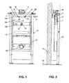
- Figur 1
- eine Ansicht einer erfindungsgemässen Ventilanordnung, die an einem Montagegestell montiert ist,
- Figur 2
- eine weitere Ansicht der Ventilanordnung und des Montagegestells gemäss
Figur 1 , - Figur 3
- ein Abschnitt der erfindungsgemässen Ventilanordnung in räumlicher Darstellung,
- Figur 4
- eine räumliche Darstellung eines Montagegestells mit einer erfindungsgemässen Ventilanordnung gemäss der
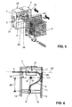
Figur 3 , - Figur 5
- eine räumliche Ansicht einer erfindungsgemässen Ventilanordnung mit einer Bedienung von vorne und
- Figur 6
- schematisch eine Ansicht eines Montagegestells mit einer erfindungsgemässen Ventilanordnung.
- Die Ventilanordnung 1 ist gemäss den
Figuren 1 bis 5 in einem Einbaukasten 7 angeordnet, der eine Öffnung 23, gegenüberliegende Wandungen 21 und 22 sowie eine Bodenwandung 29 aufweist. Die Ventilanordnung 1 besitzt ein an sich bekanntes Schliessventil 18, das beispielsweise ein Membranventil ist. Diesem ist ein hier nicht gezeigtes Drosselventil vorgelagert. Die Betätigung des Ventils kann beispielsweise über eine hier nicht gezeigte Betätigungstaste oder über einen Betätigungsknopf erfolgen. Es sind hier aber auch andere Betätigungen, insbesondere Fernbetätigungen, selbsttätige elektromagnetische Betätigungen und dergleichen möglich. Die Ventilanordnung 1 ist an eine Versorgungsleitung 2 anschliessbar, die gemässFigur 1 eine Durchgangsleitung ist. An diese Versorgungsleitung 2 können noch weitere Ventilanordnungen 1 angeschlossen sein. - Die Versorgungsleitung 2 ist über einen Ventilanschluss 4 mit dem Ventil verbunden. Der Ventilanschluss 4 ist beispielsweise als Schraubverbindung oder Pressverbindung ausgebildet. Dieser ist an der Aussenseite der Wandung 21 angeordnet. Bei geöffnetem Ventil strömt das Wasser durch den Ventilanschluss 4 in einen Einströmkanal 19, der horizontal in einem Ventilkörper 30 (
Figur 5 ) des Ventils 18 verläuft. Ausgangsseitig ist dieser Ventilkörper 30 mit einem Rohrteil 17 verbunden, der vorzugsweise ausbaubar ist und mit einem Ventilanschluss 5 verbunden ist, der aussenseitig an der Wandung 22 angeordnet ist. Dieser Ventilanschluss 5 ist ebenfalls beispielsweise als Schraubverbindung ausgebildet und verbindet das Ventil 18 mit einer Spülleitung 3. Bei geöffnetem Ventil strömt das Wasser durch den Rohrteil 17 in die Spülleitung 3. Der Rohrteil 17 bildet einen inFigur 1 angedeuteten Ausströmkanal 20. Der Einströmkanal 19 und der Ausströmkanal 20 liegen in einer inFigur 6 angedeuteten im wesentlichen geraden Linie 33, die sich in einer horizontalen Ebene befindet. - Die Ventilanordnung 1 ist gemäss den
Figuren 1, 2 und4 an einem Gestell 11 befestigt, das Vertikalstreben 12 sowie Traversen 28 und 15 aufweist. Die Traverse 28 ist jeweils am oberen Ende der beiden Vertikalstreben 12 fest montiert. An dieser Traverse 28 ist der Einbaukasten 7 mit der Ventilanordnung 1 gelagert. Bei der Ausführung gemäss denFiguren 1 bis 4 ist die Öffnung 23 des Einbaukastens 7 nach oben gerichtet. Die Betätigung erfolgt hier somit von oben. Als Einbauschutz beim Einmauern ist auf den Einbaukasten 7 in bekannter Weise ein Bauschutzkasten 8 aufgesetzt, der eine Revisionsöffnung bildet. Dieser wird mit Befestigungsschrauben 9 unter Verwendung eines Schraubendrehers 10 (Figur 3 ) am Einbaukasten 7 befestigt. Der obere Teil des Bauschutzkastens 8 wird nach dem Einbau in bekannter Weise mit einem Messer abgeschnitten. Bei der inFigur 5 gezeigten Ausführung ist die Öffnung 23 nach vorne gerichtet. Entsprechend ist der Bauschutzkasten 8 von vorne auf den Einbaukasten 7 aufgesetzt. Im Fall einer Revision ist das Ventil 18 von vorne bzw. von oben zugänglich. - Die Spülleitung 3 ist vorzugsweise eine flexible Leitung und besitzt einen ersten im wesentlichen horizontal verlaufenden Abschnitt 3b, einen Bogen 3a sowie einen schräg nach unten verlaufenden Abschnitt 3c, der eine Öffnung 31 aufweist, die sich innerhalb eines Spülanschlusses 6 befindet, welcher an der Traverse 15 befestigt ist. An diesem Spülanschluss 6 kann die Spülleitung mit einem hier nicht gezeigten Urinal, einer WC-Schüssel oder einer Bidetschüssel verbunden werden. Bei geöffnetem Ventil 18 strömt Spülwasser durch die Öffnung 31 in den entsprechenden Sanitärartikel, der an der Frontseite des Gestelles 11 befestigt ist und der eine hier nicht gezeigte Entsorgungsleitung aufweist, die mit einer Rohrschelle 16 am Gestell 11 fixiert ist.
- Die Traverse 15 und damit die Öffnung 31 kann gemäss
Figur 6 durch Verstellen der Traverse 15 nach oben sowie nach unten begrenzt verschoben werden. In derFigur 6 ist der Verstellbereich 26 mit einem Doppelpfeil angedeutet. Die oberste mögliche Position des Spülanschlusses 6' befindet sich in vergleichsweise kurzem Abstand 32 zur Ventilanordnung 1. Die Länge der Spülleitung 3 wird hier an die Höhe des Spülanschlusses 6 angepasst. Innerhalb des Bereiches 26 ist jedenfalls die Spülleitung 3 so verlegbar, dass der Bereich 3c schräg nach unten oder mindestens horizontal verläuft. Damit der Bogen 3a im wesentlichen erhalten bleibt, ist dieser an einer Leitungsführung 25 abgestützt, die an einer der Vertikalstreben befestigt ist. Die Leitungsführung 25 kann verstellbar an der Vertikalstrebe 12 befestigt sein. Bei der Ausführung gemässFigur 6 erfolgt die Betätigung von oben an einer Betätigungsvorrichtung 27. Der genannte Verlauf der Spülleitung 3 ist aber bei einer Betätigung von vorne genau gleich. Da wie erwähnt der Abstand 32 vergleichsweise klein sein kann, kann die Betätigungsvorrichtung 27 entsprechend tief angeordnet werden. Das Gestell 11 kann somit mit vergleichsweise kleiner Höhe ausgebildet werden. Was insbesondere zum Herstellen einer Ablage vorteilhaft ist. Die inFigur 6 gezeigte Leitung 2 ist keine Durchleitung. Sie könnte jedoch hier auch als Durchleitung ausgebildet sein und hier weitere nicht gezeigte Sanitäranlagen bedienen. Zum Durchführen einer als Durchleitung ausgebildeten Leitung 2 durch den Einbaukasten 7, weist diesen in den Wandungen 21 und 22 jeweils eine Öffnung 24 (Figur 5 ) auf. -
- 1
- Ventilanordnung
- 2
- Versorgungsleitung
- 3
- Spülleitung
- 3a
- Bogen
- 3b
- Abschnitt
- 3c
- Abschnitt
- 4
- Ventilanschluss
- 5
- Ventilanschluss
- 6
- Spülanschluss
- 7
- Einbaukasten
- 8
- Bauschutzkasten
- 9
- Befestigungsschraube
- 10
- Schraubendreher
- 11
- Gestell
- 12
- Vertikalstrebe
- 13
- Gebäudeboden
- 14
- Gebäudewand
- 15
- Traverse
- 16
- Rohrschelle
- 17
- Rohrteil
- 18
- Ventil
- 19
- Einströmkanal
- 20
- Ausströmkanal
- 21
- Wandung
- 22
- Wandung
- 23
- Öffnung
- 24
- Öffnung
- 25
- Leitungsführung
- 26
- Verstellbereich
- 27
- Betätigungsvorrichtung
- 28
- Traverse
- 29
- Bodenwandung
- 30
- Ventilkörper
- 31
- Öffnung
- 32
- Abstand
- 33
- Linie
Claims (10)
- Ventilanordnung an einer Spülvorrichtung, beispielsweise für ein Urinal, mit einem Spülventil (18), das einen Ventilkörper (30) aufweist, der einen an eine Versorgungsleitung (2) anschliessbaren Einströmkanal (19) und einen an eine Spülleitung (3) anschliessbaren Ausströmkanal (20) aufweist, dadurch gekennzeichnet, dass der Einströmkanal (19) und der Ausströmkanal (20) sich im wesentlichen entlang einer gemeinsamen geraden Linie erstrecken und in einer horizontalen Ebene angeordnet sind.
- Ventilanordnung nach Anspruch 1, dadurch gekennzeichnet, dass das Ventil (18) in einem Einbaukasten (7) angeordnet ist, der eine Frontseite aufweist, an welcher eine Revisionsöffnung (23) für das Spülventil angeordnet ist und die in einer horizontalen oder vertikalen Ebene verläuft und dass der Einströmkanal (19) und der Ausströmkanal (20) parallel zu dieser Frontseite verlaufen.
- Ventilanordnung nach Anspruch 1 oder 2, dadurch gekennzeichnet, dass die Spülleitung (3) einen flexible Rohrleitung ist.
- Ventilanordnung nach einem der Ansprüche 1 bis 3, dadurch gekennzeichnet, dass die Spülleitung (3) in Strömungsrichtung gesehen einen ersten im wesentlichen horizontal verlaufenden Abschnitt (3b), einen anschliessenden zweiten bogenförmigen Abschnitt (3a) und einer zur horizontalen schräg nach unten oder horizontal verlaufenden dritten Abschnitt (3c) aufweist.
- Ventilanordnung nach Anspruch 4, dadurch gekennzeichnet, dass der bogenförmige zweite Abschnitt (3a) an einer Leitungsführung (25) geführt ist.
- Ventilanordnung nach Anspruch 5, dadurch gekennzeichnet, dass die Leitungsführung (25) an einem Montagegestell (11) angeordnet ist.
- Ventilanordnung nach Anspruch 6, dadurch gekennzeichnet, dass die Leitungsführung (25) an einer Vertikalstrebe (12) befestigt ist.
- Ventilanordnung nach einem der Ansprüche 1 bis 7, dadurch gekennzeichnet, dass sie eine Durchleitung (2) aufweist, die im wesentlichen parallel und im Abstand zum Einströmkanal (19) und zum Ausströmkanal (20) verläuft.
- Ventilanordnung nach einem der Ansprüche 2 bis 8, dadurch gekennzeichnet, dass der Einbaukasten (7) gegenüberliegende parallel zu einander verlaufende Wandungen (21, 22) aufweist, und dass aussenseitig an diesen Wandungen Spülventilanschlüsse (4, 5) zum Anschliessen der Versorgungsleitung (2) und der Spülleitung (3) an das Ventil (18) aufweist.
- Ventilanordnung nach Anspruch 9, dadurch gekennzeichnet, dass die genannten Wandungen (21, 22) jeweils eine Öffnung (24) für eine Durchleitung (2) aufweisen.
Priority Applications (1)
| Application Number | Priority Date | Filing Date | Title |
|---|---|---|---|
| EP08405271.1A EP2182124B1 (de) | 2008-10-29 | 2008-10-29 | Spülvorrichtung mit einer Ventilanordnung |
Applications Claiming Priority (1)
| Application Number | Priority Date | Filing Date | Title |
|---|---|---|---|
| EP08405271.1A EP2182124B1 (de) | 2008-10-29 | 2008-10-29 | Spülvorrichtung mit einer Ventilanordnung |
Publications (2)
| Publication Number | Publication Date |
|---|---|
| EP2182124A1 true EP2182124A1 (de) | 2010-05-05 |
| EP2182124B1 EP2182124B1 (de) | 2017-08-23 |
Family
ID=40521502
Family Applications (1)
| Application Number | Title | Priority Date | Filing Date |
|---|---|---|---|
| EP08405271.1A Active EP2182124B1 (de) | 2008-10-29 | 2008-10-29 | Spülvorrichtung mit einer Ventilanordnung |
Country Status (1)
| Country | Link |
|---|---|
| EP (1) | EP2182124B1 (de) |
Cited By (1)
| Publication number | Priority date | Publication date | Assignee | Title |
|---|---|---|---|---|
| EP3896234A1 (de) * | 2020-04-16 | 2021-10-20 | Geberit International AG | Armaturenanordnung |
Families Citing this family (1)
| Publication number | Priority date | Publication date | Assignee | Title |
|---|---|---|---|---|
| WO2022236035A1 (en) | 2021-05-06 | 2022-11-10 | Fluidmaster, Inc. | Cistern system, apparatus and method |
Citations (5)
| Publication number | Priority date | Publication date | Assignee | Title |
|---|---|---|---|---|
| US3497876A (en) | 1966-02-23 | 1970-03-03 | Charles Edward Williams | Urinal flushing control system |
| DE2837710A1 (de) * | 1977-09-09 | 1979-03-22 | Geberit Ag | Spueleinrichtung fuer einzelspuelung von wandurinalen |
| EP0794371A2 (de) | 1996-03-04 | 1997-09-10 | Friatec Ag Keramik- Und Kunststoffwerke | Ventilanordnung |
| US6467734B1 (en) * | 1999-04-23 | 2002-10-22 | Securus, Inc. | Bracket for securing pipes |
| EP1936045A1 (de) | 2006-12-19 | 2008-06-25 | Geberit Technik Ag | Installationsvorrrichtung für eine sanitäre Einrichtung und sanitäre Einrichtung mit einer solchen Installationsvorrichtung |
Family Cites Families (3)
| Publication number | Priority date | Publication date | Assignee | Title |
|---|---|---|---|---|
| BE754958A (fr) * | 1969-08-21 | 1971-02-01 | G M G Heating Cy Ltd | Perfectionnements apportes ou relatifs a des systemes automatiques de chasse d'eau |
| GB2163785A (en) * | 1984-08-28 | 1986-03-05 | Metalseal | Control device for automatic flushing systems |
| DE4118213A1 (de) * | 1991-06-04 | 1992-12-10 | Peter Josef Dr Rer Nat Reuters | Spuelvorrichtung fuer toiletten |
-
2008
- 2008-10-29 EP EP08405271.1A patent/EP2182124B1/de active Active
Patent Citations (5)
| Publication number | Priority date | Publication date | Assignee | Title |
|---|---|---|---|---|
| US3497876A (en) | 1966-02-23 | 1970-03-03 | Charles Edward Williams | Urinal flushing control system |
| DE2837710A1 (de) * | 1977-09-09 | 1979-03-22 | Geberit Ag | Spueleinrichtung fuer einzelspuelung von wandurinalen |
| EP0794371A2 (de) | 1996-03-04 | 1997-09-10 | Friatec Ag Keramik- Und Kunststoffwerke | Ventilanordnung |
| US6467734B1 (en) * | 1999-04-23 | 2002-10-22 | Securus, Inc. | Bracket for securing pipes |
| EP1936045A1 (de) | 2006-12-19 | 2008-06-25 | Geberit Technik Ag | Installationsvorrrichtung für eine sanitäre Einrichtung und sanitäre Einrichtung mit einer solchen Installationsvorrichtung |
Cited By (1)
| Publication number | Priority date | Publication date | Assignee | Title |
|---|---|---|---|---|
| EP3896234A1 (de) * | 2020-04-16 | 2021-10-20 | Geberit International AG | Armaturenanordnung |
Also Published As
| Publication number | Publication date |
|---|---|
| EP2182124B1 (de) | 2017-08-23 |
Similar Documents
| Publication | Publication Date | Title |
|---|---|---|
| EP2439348B1 (de) | Montageeinrichtung für eine WC-Schüssel | |
| EP2236683B1 (de) | Duschrinnenanordnung für Wandeinbau | |
| EP3746607B1 (de) | Anordnung umfassend eine anschlussvorrichtung und einen sanitärartikel | |
| EP2159336A1 (de) | Verwendung eines Bodenablaufs | |
| EP3444408B1 (de) | Wc mit spülwasseranschluss | |
| EP2540923B1 (de) | Abwasserablauf mit Geruchsverschluss | |
| DE102014109276B4 (de) | WC-Modul mit Unterputzspülkasten für ein Dusch-WC mit integriertem, abgesichertem Frischwasseranschluss | |
| EP2182124B1 (de) | Spülvorrichtung mit einer Ventilanordnung | |
| EP3670772B1 (de) | Wc-anschlussvorrichtung zum wandseitigen anschluss eines dusch-wc und verfahren zur installation eines dusch-wc unter verwendung einer wc- anschlussvorrichtung | |
| EP2407603B1 (de) | Montageeinrichtung mit einem Montagegestell und Verfahren zum Montieren einer solchen Montageeinrichtung | |
| EP4069910B1 (de) | Ablaufvorrichtung | |
| DE10204683B4 (de) | Becken | |
| EP2690229B2 (de) | Montageeinrichtung für eine sanitäre Apparatur | |
| DE102013102379A1 (de) | Ablaufanordnung | |
| EP2412879B1 (de) | Urinal und UrinalSiphon | |
| DE19908255B4 (de) | Toilette mit heb- und senkbarem Toilettenkörper | |
| DE202015001752U1 (de) | Spüleinheit | |
| DE29806398U1 (de) | Spülsystem | |
| EP1921217A2 (de) | Klosett | |
| EP1785533B1 (de) | Vorrichtung aus Montagerahmen und höhenverstellbarer WC-Schüssel | |
| DE19510228A1 (de) | Befestigungsvorrichtung eines Spülkastens | |
| DE102004010327A1 (de) | Brauseanordnung | |
| EP0916775A2 (de) | Kastenkörper für einen Spülkasten | |
| EP2868820B1 (de) | Spülkastenanordnung | |
| EP4509665A1 (de) | Ablaufvorrichtung für eine sanitäreinrichtung mit geruchverschluss und in abflussrichtung vorgeordnetem einwegventil |
Legal Events
| Date | Code | Title | Description |
|---|---|---|---|
| PUAI | Public reference made under article 153(3) epc to a published international application that has entered the european phase |
Free format text: ORIGINAL CODE: 0009012 |
|
| AK | Designated contracting states |
Kind code of ref document: A1 Designated state(s): AT BE BG CH CY CZ DE DK EE ES FI FR GB GR HR HU IE IS IT LI LT LU LV MC MT NL NO PL PT RO SE SI SK TR |
|
| AX | Request for extension of the european patent |
Extension state: AL BA MK RS |
|
| 17P | Request for examination filed |
Effective date: 20100518 |
|
| 17Q | First examination report despatched |
Effective date: 20100624 |
|
| AKX | Designation fees paid |
Designated state(s): AT BE BG CH CY CZ DE DK EE ES FI FR GB GR HR HU IE IS IT LI LT LU LV MC MT NL NO PL PT RO SE SI SK TR |
|
| GRAP | Despatch of communication of intention to grant a patent |
Free format text: ORIGINAL CODE: EPIDOSNIGR1 |
|
| INTG | Intention to grant announced |
Effective date: 20170316 |
|
| GRAS | Grant fee paid |
Free format text: ORIGINAL CODE: EPIDOSNIGR3 |
|
| GRAA | (expected) grant |
Free format text: ORIGINAL CODE: 0009210 |
|
| AK | Designated contracting states |
Kind code of ref document: B1 Designated state(s): AT BE BG CH CY CZ DE DK EE ES FI FR GB GR HR HU IE IS IT LI LT LU LV MC MT NL NO PL PT RO SE SI SK TR |
|
| REG | Reference to a national code |
Ref country code: GB Ref legal event code: FG4D Free format text: NOT ENGLISH |
|
| REG | Reference to a national code |
Ref country code: CH Ref legal event code: EP |
|
| REG | Reference to a national code |
Ref country code: AT Ref legal event code: REF Ref document number: 921509 Country of ref document: AT Kind code of ref document: T Effective date: 20170915 |
|
| REG | Reference to a national code |
Ref country code: IE Ref legal event code: FG4D Free format text: LANGUAGE OF EP DOCUMENT: GERMAN |
|
| REG | Reference to a national code |
Ref country code: CH Ref legal event code: NV Representative=s name: ISLER AND PEDRAZZINI AG, CH |
|
| REG | Reference to a national code |
Ref country code: DE Ref legal event code: R096 Ref document number: 502008015550 Country of ref document: DE |
|
| REG | Reference to a national code |
Ref country code: NL Ref legal event code: MP Effective date: 20170823 |
|
| REG | Reference to a national code |
Ref country code: LT Ref legal event code: MG4D |
|
| PG25 | Lapsed in a contracting state [announced via postgrant information from national office to epo] |
Ref country code: HR Free format text: LAPSE BECAUSE OF FAILURE TO SUBMIT A TRANSLATION OF THE DESCRIPTION OR TO PAY THE FEE WITHIN THE PRESCRIBED TIME-LIMIT Effective date: 20170823 Ref country code: SE Free format text: LAPSE BECAUSE OF FAILURE TO SUBMIT A TRANSLATION OF THE DESCRIPTION OR TO PAY THE FEE WITHIN THE PRESCRIBED TIME-LIMIT Effective date: 20170823 Ref country code: NO Free format text: LAPSE BECAUSE OF FAILURE TO SUBMIT A TRANSLATION OF THE DESCRIPTION OR TO PAY THE FEE WITHIN THE PRESCRIBED TIME-LIMIT Effective date: 20171123 Ref country code: FI Free format text: LAPSE BECAUSE OF FAILURE TO SUBMIT A TRANSLATION OF THE DESCRIPTION OR TO PAY THE FEE WITHIN THE PRESCRIBED TIME-LIMIT Effective date: 20170823 Ref country code: LT Free format text: LAPSE BECAUSE OF FAILURE TO SUBMIT A TRANSLATION OF THE DESCRIPTION OR TO PAY THE FEE WITHIN THE PRESCRIBED TIME-LIMIT Effective date: 20170823 Ref country code: NL Free format text: LAPSE BECAUSE OF FAILURE TO SUBMIT A TRANSLATION OF THE DESCRIPTION OR TO PAY THE FEE WITHIN THE PRESCRIBED TIME-LIMIT Effective date: 20170823 |
|
| PG25 | Lapsed in a contracting state [announced via postgrant information from national office to epo] |
Ref country code: PL Free format text: LAPSE BECAUSE OF FAILURE TO SUBMIT A TRANSLATION OF THE DESCRIPTION OR TO PAY THE FEE WITHIN THE PRESCRIBED TIME-LIMIT Effective date: 20170823 Ref country code: LV Free format text: LAPSE BECAUSE OF FAILURE TO SUBMIT A TRANSLATION OF THE DESCRIPTION OR TO PAY THE FEE WITHIN THE PRESCRIBED TIME-LIMIT Effective date: 20170823 Ref country code: GR Free format text: LAPSE BECAUSE OF FAILURE TO SUBMIT A TRANSLATION OF THE DESCRIPTION OR TO PAY THE FEE WITHIN THE PRESCRIBED TIME-LIMIT Effective date: 20171124 Ref country code: BG Free format text: LAPSE BECAUSE OF FAILURE TO SUBMIT A TRANSLATION OF THE DESCRIPTION OR TO PAY THE FEE WITHIN THE PRESCRIBED TIME-LIMIT Effective date: 20171123 Ref country code: ES Free format text: LAPSE BECAUSE OF FAILURE TO SUBMIT A TRANSLATION OF THE DESCRIPTION OR TO PAY THE FEE WITHIN THE PRESCRIBED TIME-LIMIT Effective date: 20170823 Ref country code: IS Free format text: LAPSE BECAUSE OF FAILURE TO SUBMIT A TRANSLATION OF THE DESCRIPTION OR TO PAY THE FEE WITHIN THE PRESCRIBED TIME-LIMIT Effective date: 20171223 |
|
| PG25 | Lapsed in a contracting state [announced via postgrant information from national office to epo] |
Ref country code: RO Free format text: LAPSE BECAUSE OF FAILURE TO SUBMIT A TRANSLATION OF THE DESCRIPTION OR TO PAY THE FEE WITHIN THE PRESCRIBED TIME-LIMIT Effective date: 20170823 Ref country code: CZ Free format text: LAPSE BECAUSE OF FAILURE TO SUBMIT A TRANSLATION OF THE DESCRIPTION OR TO PAY THE FEE WITHIN THE PRESCRIBED TIME-LIMIT Effective date: 20170823 Ref country code: DK Free format text: LAPSE BECAUSE OF FAILURE TO SUBMIT A TRANSLATION OF THE DESCRIPTION OR TO PAY THE FEE WITHIN THE PRESCRIBED TIME-LIMIT Effective date: 20170823 |
|
| REG | Reference to a national code |
Ref country code: DE Ref legal event code: R097 Ref document number: 502008015550 Country of ref document: DE |
|
| PG25 | Lapsed in a contracting state [announced via postgrant information from national office to epo] |
Ref country code: MC Free format text: LAPSE BECAUSE OF FAILURE TO SUBMIT A TRANSLATION OF THE DESCRIPTION OR TO PAY THE FEE WITHIN THE PRESCRIBED TIME-LIMIT Effective date: 20170823 Ref country code: EE Free format text: LAPSE BECAUSE OF FAILURE TO SUBMIT A TRANSLATION OF THE DESCRIPTION OR TO PAY THE FEE WITHIN THE PRESCRIBED TIME-LIMIT Effective date: 20170823 Ref country code: IT Free format text: LAPSE BECAUSE OF FAILURE TO SUBMIT A TRANSLATION OF THE DESCRIPTION OR TO PAY THE FEE WITHIN THE PRESCRIBED TIME-LIMIT Effective date: 20170823 Ref country code: SK Free format text: LAPSE BECAUSE OF FAILURE TO SUBMIT A TRANSLATION OF THE DESCRIPTION OR TO PAY THE FEE WITHIN THE PRESCRIBED TIME-LIMIT Effective date: 20170823 |
|
| PLBE | No opposition filed within time limit |
Free format text: ORIGINAL CODE: 0009261 |
|
| STAA | Information on the status of an ep patent application or granted ep patent |
Free format text: STATUS: NO OPPOSITION FILED WITHIN TIME LIMIT |
|
| GBPC | Gb: european patent ceased through non-payment of renewal fee |
Effective date: 20171123 |
|
| REG | Reference to a national code |
Ref country code: IE Ref legal event code: MM4A |
|
| REG | Reference to a national code |
Ref country code: FR Ref legal event code: ST Effective date: 20180629 |
|
| PG25 | Lapsed in a contracting state [announced via postgrant information from national office to epo] |
Ref country code: LU Free format text: LAPSE BECAUSE OF NON-PAYMENT OF DUE FEES Effective date: 20171029 |
|
| 26N | No opposition filed |
Effective date: 20180524 |
|
| REG | Reference to a national code |
Ref country code: BE Ref legal event code: MM Effective date: 20171031 |
|
| PG25 | Lapsed in a contracting state [announced via postgrant information from national office to epo] |
Ref country code: SI Free format text: LAPSE BECAUSE OF FAILURE TO SUBMIT A TRANSLATION OF THE DESCRIPTION OR TO PAY THE FEE WITHIN THE PRESCRIBED TIME-LIMIT Effective date: 20170823 Ref country code: FR Free format text: LAPSE BECAUSE OF NON-PAYMENT OF DUE FEES Effective date: 20171031 Ref country code: BE Free format text: LAPSE BECAUSE OF NON-PAYMENT OF DUE FEES Effective date: 20171031 |
|
| PG25 | Lapsed in a contracting state [announced via postgrant information from national office to epo] |
Ref country code: MT Free format text: LAPSE BECAUSE OF FAILURE TO SUBMIT A TRANSLATION OF THE DESCRIPTION OR TO PAY THE FEE WITHIN THE PRESCRIBED TIME-LIMIT Effective date: 20170823 |
|
| PG25 | Lapsed in a contracting state [announced via postgrant information from national office to epo] |
Ref country code: IE Free format text: LAPSE BECAUSE OF NON-PAYMENT OF DUE FEES Effective date: 20171029 |
|
| PG25 | Lapsed in a contracting state [announced via postgrant information from national office to epo] |
Ref country code: GB Free format text: LAPSE BECAUSE OF NON-PAYMENT OF DUE FEES Effective date: 20171123 |
|
| PG25 | Lapsed in a contracting state [announced via postgrant information from national office to epo] |
Ref country code: HU Free format text: LAPSE BECAUSE OF FAILURE TO SUBMIT A TRANSLATION OF THE DESCRIPTION OR TO PAY THE FEE WITHIN THE PRESCRIBED TIME-LIMIT; INVALID AB INITIO Effective date: 20081029 |
|
| PG25 | Lapsed in a contracting state [announced via postgrant information from national office to epo] |
Ref country code: CY Free format text: LAPSE BECAUSE OF NON-PAYMENT OF DUE FEES Effective date: 20170823 |
|
| PG25 | Lapsed in a contracting state [announced via postgrant information from national office to epo] |
Ref country code: TR Free format text: LAPSE BECAUSE OF FAILURE TO SUBMIT A TRANSLATION OF THE DESCRIPTION OR TO PAY THE FEE WITHIN THE PRESCRIBED TIME-LIMIT Effective date: 20170823 |
|
| PG25 | Lapsed in a contracting state [announced via postgrant information from national office to epo] |
Ref country code: PT Free format text: LAPSE BECAUSE OF FAILURE TO SUBMIT A TRANSLATION OF THE DESCRIPTION OR TO PAY THE FEE WITHIN THE PRESCRIBED TIME-LIMIT Effective date: 20170823 |
|
| P01 | Opt-out of the competence of the unified patent court (upc) registered |
Effective date: 20230516 |
|
| PGFP | Annual fee paid to national office [announced via postgrant information from national office to epo] |
Ref country code: CH Payment date: 20231102 Year of fee payment: 16 Ref country code: AT Payment date: 20231020 Year of fee payment: 16 |
|
| REG | Reference to a national code |
Ref country code: AT Ref legal event code: PC Ref document number: 921509 Country of ref document: AT Kind code of ref document: T Owner name: GEBERIT INTERNATIONAL AG, CH Effective date: 20241118 |
|
| REG | Reference to a national code |
Ref country code: CH Ref legal event code: PL |
|
| REG | Reference to a national code |
Ref country code: AT Ref legal event code: MM01 Ref document number: 921509 Country of ref document: AT Kind code of ref document: T Effective date: 20241029 |
|
| PG25 | Lapsed in a contracting state [announced via postgrant information from national office to epo] |
Ref country code: CH Free format text: LAPSE BECAUSE OF NON-PAYMENT OF DUE FEES Effective date: 20241031 |
|
| PG25 | Lapsed in a contracting state [announced via postgrant information from national office to epo] |
Ref country code: AT Free format text: LAPSE BECAUSE OF NON-PAYMENT OF DUE FEES Effective date: 20241029 |
|
| PGFP | Annual fee paid to national office [announced via postgrant information from national office to epo] |
Ref country code: DE Payment date: 20251021 Year of fee payment: 18 |