EP2181839B1 - Stempel für eine Rundläuferpresse - Google Patents
Stempel für eine Rundläuferpresse Download PDFInfo
- Publication number
- EP2181839B1 EP2181839B1 EP09012255.7A EP09012255A EP2181839B1 EP 2181839 B1 EP2181839 B1 EP 2181839B1 EP 09012255 A EP09012255 A EP 09012255A EP 2181839 B1 EP2181839 B1 EP 2181839B1
- Authority
- EP
- European Patent Office
- Prior art keywords
- punch
- head
- press
- insert
- shaft
- Prior art date
- Legal status (The legal status is an assumption and is not a legal conclusion. Google has not performed a legal analysis and makes no representation as to the accuracy of the status listed.)
- Not-in-force
Links
Images
Classifications
-
- B—PERFORMING OPERATIONS; TRANSPORTING
- B30—PRESSES
- B30B—PRESSES IN GENERAL
- B30B15/00—Details of, or accessories for, presses; Auxiliary measures in connection with pressing
- B30B15/06—Platens or press rams
- B30B15/065—Press rams
-
- B—PERFORMING OPERATIONS; TRANSPORTING
- B30—PRESSES
- B30B—PRESSES IN GENERAL
- B30B11/00—Presses specially adapted for forming shaped articles from material in particulate or plastic state, e.g. briquetting presses, tabletting presses
- B30B11/02—Presses specially adapted for forming shaped articles from material in particulate or plastic state, e.g. briquetting presses, tabletting presses using a ram exerting pressure on the material in a moulding space
- B30B11/08—Presses specially adapted for forming shaped articles from material in particulate or plastic state, e.g. briquetting presses, tabletting presses using a ram exerting pressure on the material in a moulding space co-operating with moulds carried by a turntable
-
- B—PERFORMING OPERATIONS; TRANSPORTING
- B30—PRESSES
- B30B—PRESSES IN GENERAL
- B30B15/00—Details of, or accessories for, presses; Auxiliary measures in connection with pressing
- B30B15/02—Dies; Inserts therefor; Mounting thereof; Moulds
- B30B15/026—Mounting of dies, platens or press rams
-
- Y—GENERAL TAGGING OF NEW TECHNOLOGICAL DEVELOPMENTS; GENERAL TAGGING OF CROSS-SECTIONAL TECHNOLOGIES SPANNING OVER SEVERAL SECTIONS OF THE IPC; TECHNICAL SUBJECTS COVERED BY FORMER USPC CROSS-REFERENCE ART COLLECTIONS [XRACs] AND DIGESTS
- Y10—TECHNICAL SUBJECTS COVERED BY FORMER USPC
- Y10T—TECHNICAL SUBJECTS COVERED BY FORMER US CLASSIFICATION
- Y10T83/00—Cutting
- Y10T83/929—Tool or tool with support
- Y10T83/9411—Cutting couple type
- Y10T83/9423—Punching tool
-
- Y—GENERAL TAGGING OF NEW TECHNOLOGICAL DEVELOPMENTS; GENERAL TAGGING OF CROSS-SECTIONAL TECHNOLOGIES SPANNING OVER SEVERAL SECTIONS OF THE IPC; TECHNICAL SUBJECTS COVERED BY FORMER USPC CROSS-REFERENCE ART COLLECTIONS [XRACs] AND DIGESTS
- Y10—TECHNICAL SUBJECTS COVERED BY FORMER USPC
- Y10T—TECHNICAL SUBJECTS COVERED BY FORMER US CLASSIFICATION
- Y10T83/00—Cutting
- Y10T83/929—Tool or tool with support
- Y10T83/9457—Joint or connection
-
- Y—GENERAL TAGGING OF NEW TECHNOLOGICAL DEVELOPMENTS; GENERAL TAGGING OF CROSS-SECTIONAL TECHNOLOGIES SPANNING OVER SEVERAL SECTIONS OF THE IPC; TECHNICAL SUBJECTS COVERED BY FORMER USPC CROSS-REFERENCE ART COLLECTIONS [XRACs] AND DIGESTS
- Y10—TECHNICAL SUBJECTS COVERED BY FORMER USPC
- Y10T—TECHNICAL SUBJECTS COVERED BY FORMER US CLASSIFICATION
- Y10T83/00—Cutting
- Y10T83/929—Tool or tool with support
- Y10T83/9457—Joint or connection
- Y10T83/9473—For rectilinearly reciprocating tool
- Y10T83/9476—Tool is single element with continuous cutting edge [e.g., punch, etc.]
Definitions
- the invention relates to a stamp for a rotary press according to claim 1.
- a rotary press contains a plurality of upper and lower punches, which are guided in suitable guide bores of punch guides and cooperate with bores of a die plate.
- the individual punches have a shaft and a head at one end, which cooperates with pressure rollers of the press.
- a punch insert is arranged, which is designed separately and can be connected via suitable fastening means with the shaft. The connection is made with the help of screws or pins.
- DE 829 48 242 or JP 'A'11347798 It has become known to attach a punch insert with the aid of a clamping screw on the punch shaft.
- the head and the punch shaft on a through bore through which a threaded rod is passed, which is screwed with its threaded end into an internal thread of the punch insert.
- the head of the threaded rod is recessed in a recess of the stamp head.
- the document DE 571 885 C discloses a ram according to the preamble of claim 1.
- the known stamp constructions have some disadvantages.
- the removal and installation of the stamp inserts is expensive, especially time consuming.
- An exchange of the stamp inserts within the rotary press is not possible.
- the attachment of the stamp inserts is susceptible to interference and exposed to high wear. Problems also arise with regard to centering and alignment of the punch inserts, especially in non-round dies.
- the invention is therefore an object of the invention to provide a ram for a rotary press, which ensures easy installation and removal of the punch insert and allows cleaning within the press.
- the pull rod has a clamping head at the end facing away from the stamp head with at least one connecting section.
- the connecting portion is engageable with a facing recess of the punch insert.
- clamping means are arranged with which the pull rod in the direction of the punch head can be tensioned.
- the clamping head has at least one radial projection, which allows in one rotational position of the punch insert relative to the pull rod an introduction of the clamping head into the recess and engages behind the undercut in the recess in another rotational position.
- the punch insert is connected to the facing end of the drawbar, namely the chuck.
- the pull rod is actuated to pull the punch insert axially against the punch shaft.
- the pull rod has a thread on which on the punch head side a clamping nut is screwed, which is supported on a shoulder in the axial through hole.
- the tension can also be applied by a spring instead of a clamping nut, which biases the pull rod in the direction of the punch head.
- the inventive compound of a punch insert with the punch shaft allows outwardly only smooth surfaces of the punch shaft and punch insert. This results in a good washability of the entire stamp, since neither stamp shank nor stamp insert on the outside have threads, joints or other unfavorable geometries. Assembly and disassembly of the stamp insert is possible within a very short time, even within the rotary press, even by automatic means.
- the punches are known to be held during their movement in the rotary press in certain sections of curved sections. These sections can then be manipulated on the punches to install or remove the punch insert.
- the outer contour of the punch insert near the punch shaft is preferably congruent to the outer contour of the punch shaft, so that no stepped transitions are present.
- the plant of the punch insert at the facing end of the stamp shank is preferably carried out via plane Surfaces.
- a friction fit can be obtained via these surfaces, which prevents a relative rotation of the punch insert to the punch shaft.
- a position pin can be provided which is inserted in the punch shaft and cooperates with a facing hole in the punch insert.
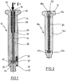
- stamp head 12 and punch shaft 14 have an axial bore 16.
- the bore 16 has the punch head 12 end facing a bore portion 18 of larger diameter.
- the bore 16 receives a pull rod 20 which has a clamping head 22 at the lower end.
- a nut 24 serves as an abutment for a coil spring 26, located on a Washer 28 is supported.
- the disc 28 is supported on the facing shoulder of the bore portion 18 from. Below the disc 28, an elastomeric seal 30 is arranged. It is intended to prevent liquid or dust from passing from the stamp head 12 in the direction of the through hole 18.
- a punch insert 32 is connected by the clamping head 22, which engages in a recess 34 of the punch insert 32, is clamped against the facing end of the shaft 14.
- a position pin 36 is seated in an axially parallel blind bore of the shaft 14. It cooperates with a hole 38 at the facing end of the punch insert 32.
- a gasket 40 made of plastic.
- the peripheral contour of the punch insert 32 near the punch shaft 14 is congruent with that of the punch shaft 14, and the punch shaft 14 and punch insert 32 are abutted against each other via planar surfaces perpendicular to the axis of the punch 10. Therefore, there is no stepped transition to the outside and no gap in which impurities can enter.
- a pressing tool 42 is integrally formed.
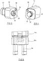
- the attachment of the punch insert 32 is clear from the FIGS. 3 and 4 out. How out FIG. 4 shows, the chuck 22 diametrically opposed radial lugs 44.
- the punch insert 32 has in the recess 34 diametrically opposite axially parallel grooves 46. They are adapted to receive the radial lugs 44 when the punch insert is set against the shaft 14 and the chuck 22 into the recess 34 dips. At the end of the grooves 46 transversely to the axis extending shoulders are formed by a free rotation 48, which form an undercut in the recess 34.
- a hole 50 is formed in the punch insert, which is formed in the radial direction as a slot. In the circumferential direction, it is suitable to receive the position pin 36 fitting.
- the punch insert 32 is held in a rotational position such that the radial projections 44 are aligned with the grooves 46. Then the punch insert 32 is advanced against the shaft 14 until the position pin 36 abuts against the facing planar surface of the punch insert 32. Subsequently, the punch insert 32 is rotated by about 45 °, whereby the radial lugs 44 or lugs engage behind the shoulders formed by the free rotation. The rotation is carried out until the position pin 36 is above the hole 50. Subsequently, the pull rod 20 is tightened, so that the punch insert according to FIG. 1 is stretched against the shaft 14 of the punch 10. In order to carry out the described assembly, according to arrow F in FIG.
- FIG. 2 a stamp 10a can be seen, which the stamp 10 in FIG. 1 essentially resembles. He takes a pull rod 20a in a corresponding Through hole, wherein the through hole near the punch head 12 has an extended bore portion 18 a.
- a clamping nut 52 is screwed onto a thread of the drawbar 20a, so that on the drawbar 20a, a tensile force can be exerted in the direction of the punch head 12 to clamp a punch insert 32a against the punch shaft 14a.
- the connection of the clamping head 22a with the punch insert 32a can be done in the same way as this FIG. 1 has been described.
- the clamping nut 52 is axially secured by a locking ring 54 in the bore portion 18 a.
- FIG. 5 shows the lower end of a shaft 14b of a further not shown pressing ram, to which a punch insert 32b is attached in a manner as described in connection with the FIGS. 1 to 3 has been described. Therefore, this connection will not be discussed in more detail.
- the peculiarity of the stamp insert 32b after FIG. 5 is that the punch insert 32b has four pressing sections 56. In operation, the pressing portions 56 cooperate with four die holes simultaneously.
Landscapes
- Engineering & Computer Science (AREA)
- Mechanical Engineering (AREA)
- Mounting, Exchange, And Manufacturing Of Dies (AREA)
- Automatic Assembly (AREA)
- Punching Or Piercing (AREA)
Description
- Die Erfindung bezieht sich auf einen Stempel für eine Rundläuferpresse nach dem Patentanspruch 1.
- Eine Rundläuferpresse enthält bekanntlich eine Mehrzahl von Ober- und Unterstempeln, die in geeigneten Führungsbohrungen von Stempelführungen geführt sind und mit Bohrungen einer Matrizenplatte zusammenwirken. Die einzelnen Stempel weisen einen Schaft auf sowie einen Kopf an einem Ende, der mit Druckrollen der Presse zusammenwirkt. An dem vom Stempelkopf abgewandten Ende ist ein Stempeleinsatz angeordnet, der getrennt ausgeführt und über geeignete Befestigungsmittel mit dem Schaft verbindbar ist. Die Verbindung erfolgt mit Hilfe von Schrauben oder Stiften. Es ist jedoch auch bekannt, Preßstempel einteilig auszuführen. Aus
DE 829 48 242 oderJP 'A'11347798 - Das Dokument
DE 571 885 C offenbart ein Pressstempel gemäß dem Oberbegriff des Anspruchs 1. - Die bekannten Stempelkonstruktionen haben einige Nachteile. Der Aus- und Einbau der Stempeleinsätze ist aufwendig, insbesondere zeitaufwendig. Ein Austausch der Stempeleinsätze innerhalb der Rundläuferpresse ist nicht möglich. Die Befestigung der Stempeleinsätze ist störanfällig und einem hohen Verschleiß ausgesetzt. Probleme treten auch auf im Hinblick auf Zentrierung und Ausrichtung der Stempeleinsätze, insbesondere bei nicht runden Preßformen. Schließlich ist auch die Reinigungsfähigkeit der bekannten Preßstempel schlecht, insbesondere, wenn sie in der Presse verbleiben sollen (CIP = Cleaning in Place). Grund ist das Vorhandensein von Gewinden, Ecken und Fugen.
- Der Erfindung liegt daher die Aufgabe zugrunde, einen Preßstempel für eine Rundläuferpresse zu schaffen, der eine leichte Ein- und Ausbaubarkeit des Stempeleinsatzes gewährleistet und eine Reinigung innerhalb der Presse erlaubt.
- Diese Aufgabe wird durch die Merkmale des Patentanspruchs 1 gelöst.
- Bei dem erfindungsgemäßen Preßstempel weist die Zugstangean dem dem Stempelkopf abgewandten Ende einen Spannkopf auf mit mindestens einem Verbindungsabschnitt. Der Verbindungsabschnitt ist mit einer zugekehrten Ausnehmung des Stempeleinsatzes in Verbindung bringbar. In der axialen Durchbohrung sind Spannmittel angeordnet, mit denen die Zugstange in Richtung des Stempelkopfes spannbar ist. Der Spannkopf weist mindestens einen radialen Ansatz auf, der in der einen Drehstellung des Stempeleinsatzes relativ zur Zugstange eine Einführung des Spannkopfes in die Ausnehmung ermöglicht und in einer anderen Drehstellung den Hinterschnitt in der Ausnehmung hintergreift.
- Bei der Montage wird der Stempeleinsatz mit dem zugekehrten Ende der Zugstange, nämlich dem Spannkopf, verbunden. Anschließend wird die Zugstange betätigt, um den Stempeleinsatz axial gegen den Stempelschaft zu ziehen. Dies kann nach einer Ausgestaltung der Erfindung dadurch geschehen, dass die Zugstange ein Gewinde aufweist, auf das auf der Stempelkopfseite eine Spannmutter geschraubt ist, die sich auf einer Schulter in der axialen Durchbohrung abstützt. Durch Drehung der Spannmutter wird die Zugstange unter Zugspannung gesetzt und kann somit den Stempeleinsatz gegen den Stempelschaft anziehen.
- Die Zugspannung kann anstelle von einer Spannmutter auch von einer Feder aufgebracht werden, welche die Zugstange in Richtung Stempelkopf vorspannt.
- Die erfindungsgemäße Verbindung eines Stempeleinsatzes mit dem Stempelschaft ermöglicht nach außen nur glatte Flächen von Stempelschaft und Stempeleinsatz. Dadurch ergibt sich eine gute Waschbarkeit des gesamten Stempels, da weder Stempelschaft noch Stempeleinsatz an der Außenseite Gewinde, Fugen oder andere ungünstige Geometrien aufweisen. Montage und Demontage des Stempeleinsatzes ist innerhalb kürzester Zeit möglich, und zwar auch innerhalb der Rundläuferpresse, auch auf automatischem Wege. Die Stempel werden bekanntlich während ihrer Bewegung in der Rundläuferpresse in bestimmten Strecken von Kurvenabschnitten gehalten. In diesen Abschnitten kann dann an den Stempeln manipuliert werden, um den Stempeleinsatz einzubauen bzw. zu entfernen.
- Da bei der Montage des Stempeleinsatzes dieser zur Matrizenbohrung ausgerichtet ist, können die Toleranzen von Stempelschaft, Matrizenbohrung und Stempelführung groß gewählt werden. Dies ermöglicht erhebliche Einsparungen bei der Herstellung der Stempel, Matrizen und Segmente für die Matrizenplatte und die Stempelführung.
- Die Außenkontur des Stempeleinsatzes nahe dem Stempelschaft ist vorzugsweise kongruent zur Außenkontur des Stempelschaftes, sodass keine gestuften Übergänge vorhanden sind. Die Anlage des Stempeleinsatzes am zugekehrten Ende des Stempelschaftes erfolgt vorzugsweise über plane
Flächen. Über diese Flächen kann außerdem ein Reibschluss erhalten werden, der eine Relatiwerdrehung des Stempeleinsatzes zum Stempelschaft verhindert. Alternativ kann ein Positionsstift vorgesehen werden, der im Stempelschaft eingebracht ist und mit einem zugekehrten Loch im Stempeleinsatz zusammenwirkt. - Ausführungsbeispiele der Erfindung werden nachfolgend anhand von Zeichnungen näher erläutert.
- Fig. 1
- zeigt einen Schnitt durch eine erste Ausführungsform eines Preßstempels nach der Erfindung,
- Fig. 2
- zeigt einen Schnitt durch eine zweite Ausführungsform eines Preßstempels nach der Erfindung,
- Fig. 3
- zeigt perspektivisch das obere Ende des Stempeleinsatzes nach
Figur 1 , - Fig. 4
- zeigt perspektivisch das dem Stempeleinsatz zugekehrte Ende des Stempelschaftes nach
Figur 1 , - Fig. 5
- zeigt perspektivisch einen alternativen Stempeleinsatz.
- In
Figur 1 ist ein Preßstempel 10 dargestellt mit einem Stempelkopf 12 und einem Stempelschaft 14. Stempelkopf 12 und Stempelschaft 14 weisen eine axiale Durchbohrung 16 auf. Die Durchbohrung 16 hat am Stempelkopf 12 zugewandten Ende einen Bohrungsabschnitt 18 mit größerem Durchmesser. Die Durchbohrung 16 nimmt eine Zugstange 20 auf, die am unteren Ende einen Spannkopf 22 aufweist. Am oberen Ende ist die Zugstange 20 mit einem Gewinde versehen, auf das eine Mutter 24 aufgeschraubt ist. Die Mutter 24 dient als Widerlager für eine Schraubenfeder 26, die sich auf einer Scheibe 28 abstützt. Die Scheibe 28 stützt sich auf der zugekehrten Schulter des Bohrungsabschnitts 18 ab. Unterhalb der Scheibe 28 ist eine Elastomerdichtung 30 angeordnet. Sie soll verhindern, dass Flüssigkeit oder Staub vom Stempelkopf 12 her in Richtung Durchbohrung 18 gelangt. - Mit dem Schaft 14 ist ein Stempeleinsatz 32 verbunden, indem der Spannkopf 22, der in einer Ausnehmung 34 des Stempeleinsatzes 32 eingreift, gegen das zugekehrte Ende des Schaftes 14 gespannt wird. Ein Positionsstift 36 sitzt in einer achsparallelen Blindbohrung des Schaftes 14. Er wirkt mit einem Loch 38 am zugekehrten Ende des Stempeleinsatzes 32 zusammen. Zwischen dem Spannkopf 22 und der zugekehrten Fläche des Stempelschaftes 14 sitzt eine Flachdichtung 40 aus Kunststoff.
- Die Umfangskontur des Stempeleinsatzes 32 nahe dem Stempelschaft 14 ist kongruent zu der des Stempelschafts 14, und Stempelschaft 14 und Stempeleinsatz 32 liegen über plane Flächen, die senkrecht auf der Achse des Stempels 10 stehen, gegeneinander. Daher ist nach außen kein gestufter Übergang vorhanden und auch keine Fuge, in die Verunreinigungen eintreten können. Mit dem Stempeleinsatz 32 ist einteilig ein Presswerkzeug 42 geformt.
- Die Anbringung des Stempeleinsatzes 32 geht deutlicher aus den
Figuren 3 und 4 hervor. Wie ausFigur 4 hervorgeht, weist der Spannkopf 22 diametral gegenüberliegende radiale Ansätze 44 auf. Der Stempeleinsatz 32 weist in der Ausnehmung 34 diametral gegenüberliegend achsparallele Nuten 46 auf. Sie sind geeignet, die radialen Ansätze 44 aufzunehmen, wenn der Stempeleinsatz gegen den Schaft 14 gesetzt wird und der Spannkopf 22 in die Ausnehmung 34 eintaucht. Am Ende der Nuten 46 sind quer zur Achse erstreckende Schultern durch eine Freidrehung 48 geformt, die einen Hinterschnitt in der Ausnehmung 34 bilden. Exzentrisch zur Ausnehmung 34 ist ein Loch 50 in den Stempeleinsatz eingeformt, das in radialer Ausrichtung als Langloch gebildet ist. In Umfangsrichtung ist es geeignet, den Positionsstift 36 passend aufzunehmen. - Bei der Montage des Stempeleinsatzes 32 am Stempel 10 wird der Stempeleinsatz in einer Drehlage gehalten, dass die radialen Ansätze 44 zu den Nuten 46 ausgerichtet sind. Dann wird der Stempeleinsatz 32 so weit gegen den Schaft 14 vorgeschoben, bis der Positionsstift 36 gegen die zugekehrte plane Fläche des Stempeleinsatzes 32 anstößt. Anschließend wird der Stempeleinsatz 32 um etwa 45° gedreht, wodurch die radialen Ansätze 44 oder Nasen die durch die Freidrehung gebildeten Schultern hintergreifen. Die Drehung wird so weit durchgeführt, bis der Positionsstift 36 über dem Loch 50 liegt. Anschließend wird die Zugstange 20 angezogen, sodass der Stempeleinsatz gemäß
Figur 1 gegen den Schaft 14 des Stempels 10 gespannt ist. Um die beschriebene Montage durchzuführen, wird entsprechend Pfeil F inFigur 1 eine Kraft auf die Zugstange 20 ausgeübt, sodass diese unter Kompression der Feder 26 über das Ende des Schaftes 14 ausreichend übersteht, dass die beschriebene Montage des Stempeleinsatzes 32 erfolgen kann. Dieser Weg entspricht zum Beispiel dem Weg S inFigur 1 . Nach der Montage wird die Kraft F entfernt, sodass die Feder 26 ihre Spannkraft auf den Stempeleinsatz 32 aufbringen kann. - In
Figur 2 ist ein Stempel 10a zu erkennen, der dem Stempel 10 inFigur 1 im Wesentlichen gleicht. Er nimmt eine Zugstange 20a in einer entsprechenden Durchbohrung auf, wobei die Durchbohrung nahe dem Stempelkopf 12 einen erweiterten Bohrungsabschnitt 18a aufweist. Eine Spannmutter 52 ist auf ein Gewinde der Zugstange 20a aufgeschraubt, sodass auf die Zugstange 20a eine Zugkraft in Richtung Stempelkopf 12 ausgeübt werden kann, um einen Stempeleinsatz 32a gegen den Stempelschaft 14a zu spannen. Die Verbindung des Spannkopfes 22a mit dem Stempeleinsatz 32a kann in gleicher Weise erfolgen, wie dies zuFigur 1 beschrieben wurde. Die Spannmutter 52 ist durch einen Sicherungsring 54 in den Bohrungsabschnitt 18a axial gesichert. -
Figur 5 zeigt das untere Ende eines Schaftes 14b eines weiter nicht dargestellten Preßstempels, an den ein Stempeleinsatz 32b in einer Weise befestigt ist, wie dies in Verbindung mit denFiguren 1 bis 3 beschrieben wurde. Daher wird auf diese Verbindung nicht mehr näher eingegangen. Die Besonderheit des Stempeleinsatzes 32b nachFigur 5 ist die, dass der Stempeleinsatz 32b vier Preßabschnitte 56 aufweist. Im Betrieb wirken die Preßabschnitte 56 mit vier Matrizenbohrungen gleichzeitig zusammen.
Claims (13)
- Pressstempel für eine Rundläuferpresse, mit einem Stempelschaft (14, 14a), der an seinem einen Ende einen Stempelkopf (12, 12a) und am anderen Ende Mittel zur Aufnahme eines getrennten Stempeleinsatzes (32, 32a) aufweist und Befestigungsmitteln zur lösbaren Befestigung des Stempeleinsatzes (32, 32a) am Stempelschaft (14, 14a), wobei Stempelkopf (12, 12a) und Stempelschaft (14, 14a) eine axiale Durchbohrung (20) aufweisen, die axiale Durchbohrung eine Zugstange (20, 20a) aufnimmt, die an dem dem Stempelkopf (12, 12a) abgewandten Ende einen Verbindungsabschnitt aufweist, der lösbar mit einer dem Stempelschaft (14, 14a) zugewandten Ausnehmung des Stempeleinsatzes (32, 32a) zusammenwirkt und in der axialen Durchbohrung (16) Spannmittel angeordnet sind, mit denen die Zugstange (20, 20a) in Richtung des Stempelkopfes (12, 12a) spannbar ist, dadurch gekennzeichnet, dass die Zugstange (20, 20a) an der dem Stempelkopf (12, 12a) abgewandten Ende einen Spannkopf (22, 22a) aufweist, der Spannkopf (22, 22a) eine radiale Erstreckung aufweist, die größer ist als der Radius der axialen Durchbohrung (16), die Ausnehmung (34, 34a) mit einem Hinterschnitt versehen ist, derart, dass in einer ersten Drehlage der Stempeleinsatz (32, 32a) relativ zur Zugstange (20, 20a) der Spannkopf (22, 22a) in die Ausnehmung (34, 34a) einführbar ist und in einer zweiten Drehlage die radiale Erstreckung die Hinterschneidung hintergreift.
- Preßstempel nach Anspruch 1, dadurch gekennzeichnet dass die Zugstange (20a) ein Gewinde aufweist, auf die stempelkopfseitig eine Spannmutter (52) aufgeschraubt ist, die sich an einer Schulter in der axialen Durchbohrung (18a) abstützt.
- Preßstempel nach Anspruch 2, dadurch gekennzeichnet dass die Mutter (52) mittels eines Sicherungsringes (54) axial in der Durchbohrung (18a) gehalten ist.
- Preßstempel nach Anspruch 1 oder 2, dadurch gekennzeichnet dass ein Bohrungsabschnitt (18) nahe dem Stempelkopf (12) einen größeren Durchmesser aufweist als der übrige Teil der Durchbohrung (20), eine Schrauben-, Teller- oder Elastomerfeder in dem Bohrungsabschnitt (18) aufgenommen ist, der sich an dem stempelkopfseitigen Ende an einem Anschlag der Zugstange (20) abstützt.
- Preßstempel nach Anspruch 4, dadurch gekennzeichnet dass die Feder (26) sich über eine Scheibe (28) an einer Schulter des Bohrungsabschnitts (18) abstützt.
- Preßstempel nach Anspruch 5, dadurch gekennzeichnet dass zwischen Scheibe (28) und Schulter eine Dichtung (30) aus einem Elastomer angeordnet ist.
- Preßstempel nach einem der Ansprüche 4 bis 6, dadurch gekennzeichnet dass der Anschlag von einer Anschlagmutter (24) gebildet ist, die auf ein Gewinde der Zugstange (20) geschraubt ist.
- Preßstempel nach einem der Ansprüche 1 bis 7, dadurch gekennzeichnet dass der Spannkopf (22) zwei gegenüberliegende radiale Ansätze (44) oder Nasen aufweist und die Ausnehmung (34) zwei achsparallele Nuten (46), durch welche die radialen Ansätze (44) in die Ausnehmung (34) einführbar sind und die Hinterschneidung in der Ausnehmung (34) von Schultern gebildet ist, die von den radialen Ansätzen (44) hintergriffen werden.
- Preßstempel nach einem der Ansprüche 1 bis 8, dadurch gekennzeichnet dass die Außenkontur des Stempeleinsatzes (32, 32a) zur Außenkontur des Stempelschaftes (14,14a) nahe dem Stempeleinsatzende kongruent ist.
- Preßstempel nach einem der Ansprüche 1 bis 9, dadurch gekennzeichnet dass Stempelschaft (14, 14a) und Stempeleinsatz (32, 32a) über plane Flächen aneinander liegen.
- Preßstempel nach einem der Ansprüche 1 bis 10, dadurch gekennzeichnet dass das dem Stempelkopf (12) abgewandte Ende des Stempelschaftes (14, 14a) exzentrisch eine Positionsbohrung aufweist, zur Aufnahme eines Positionsstiftes (36) und der Stempeleinsatz (32) ein Loch (50) das das aus der Bohrung des Stempelschaftes hinausstehende Ende des Positionsstiftes aufnimmt.
- Preßstempel nach Anspruch 11, dadurch gekennzeichnet dass das Loch (50) in radialer Richtung als Langloch ausgeführt ist.
- Preßstempel nach einem der Ansprüche 1 bis 12, dadurch gekennzeichnet dass der Stempeleinsatz (32b) mit mehreren parallelen Stempelabschnitten (56) versehen ist.
Applications Claiming Priority (1)
| Application Number | Priority Date | Filing Date | Title |
|---|---|---|---|
| DE102008053453A DE102008053453B4 (de) | 2008-10-28 | 2008-10-28 | Stempel für eine Rundläuferpresse |
Publications (3)
| Publication Number | Publication Date |
|---|---|
| EP2181839A2 EP2181839A2 (de) | 2010-05-05 |
| EP2181839A3 EP2181839A3 (de) | 2013-02-20 |
| EP2181839B1 true EP2181839B1 (de) | 2018-09-26 |
Family
ID=41491542
Family Applications (1)
| Application Number | Title | Priority Date | Filing Date |
|---|---|---|---|
| EP09012255.7A Not-in-force EP2181839B1 (de) | 2008-10-28 | 2009-09-28 | Stempel für eine Rundläuferpresse |
Country Status (3)
| Country | Link |
|---|---|
| US (1) | US8490529B2 (de) |
| EP (1) | EP2181839B1 (de) |
| DE (1) | DE102008053453B4 (de) |
Cited By (2)
| Publication number | Priority date | Publication date | Assignee | Title |
|---|---|---|---|---|
| DE102024124014A1 (de) | 2024-08-22 | 2026-02-26 | Ritter Pharma-Technik Gmbh | Stempelschaft für einen Tablettierstempel, ein Tablettierstempel und ein Tablettierwerkzeug |
| DE102024124021A1 (de) | 2024-08-22 | 2026-02-26 | Ralf Ritter | Stempeleinsatz für einen Tablettierstempel, ein Tablettierstempel und ein Tablettierwerkzeug |
Families Citing this family (5)
| Publication number | Priority date | Publication date | Assignee | Title |
|---|---|---|---|---|
| TW201016360A (en) * | 2008-10-27 | 2010-05-01 | Rexon Ind Corp Ltd | Quick release device for sawing machine |
| JP5658980B2 (ja) * | 2010-11-17 | 2015-01-28 | 株式会社菊水製作所 | 粉体圧縮成形機の杵 |
| CN102267245A (zh) * | 2011-08-12 | 2011-12-07 | 成都科盛石油科技有限公司 | 压力机中压制工件的冲头 |
| DE102016113724B4 (de) | 2016-07-26 | 2019-01-17 | Fette Compacting Gmbh | Stempel für eine Rundläuferpresse |
| DE102019112547A1 (de) | 2019-05-14 | 2020-11-19 | Felss Systems Gmbh | Bearbeitungseinheit und Bearbeitungsmaschine zur Bearbeitung eines Werkstücks an einer Werkstückwand sowie Verfahren zur Herstellung einer Bearbeitungseinheit der genannten Art |
Family Cites Families (15)
| Publication number | Priority date | Publication date | Assignee | Title |
|---|---|---|---|---|
| US458076A (en) * | 1891-08-18 | Punch | ||
| DE571885C (de) * | 1930-04-08 | 1933-03-07 | Bisterfeld & Stolting | Maschine zum Herstellen von Formstuecken aus Kunstharzen |
| US3791034A (en) * | 1972-03-23 | 1974-02-12 | C Carver | Hole punching tool |
| DE2948242C2 (de) * | 1979-11-30 | 1982-10-28 | Sandoz AG, 8500 Nürnberg | Stempel für Pressen mit einer Kulissenführung |
| US4375774A (en) * | 1979-12-26 | 1983-03-08 | Wilson Tool Company | Adjustable punch head |
| US4487566A (en) * | 1983-07-11 | 1984-12-11 | Barna Alex J | Punching tool having interchangeable punches |
| JPH0342199A (ja) * | 1989-07-06 | 1991-02-22 | Toshiba Mach Co Ltd | 杵および臼のクランプ装置 |
| JP3042199B2 (ja) | 1992-09-11 | 2000-05-15 | 松下電器産業株式会社 | 自動製パン機 |
| US5329835A (en) * | 1992-10-07 | 1994-07-19 | Wilson Tool International, Inc. | Adjustable length punch set assembly |
| JP3847412B2 (ja) * | 1997-05-02 | 2006-11-22 | 株式会社村田製作所 | ロータリ式粉体圧縮成形装置 |
| JPH11347798A (ja) * | 1998-06-02 | 1999-12-21 | Fujitsu Towa Electron Ltd | 成形用金型 |
| DE19854075A1 (de) * | 1998-11-24 | 2000-05-25 | Henkel Kgaa | Verfahren zur Serienfertigung von Formkörpern mit geringer Härteschwankung |
| US6276247B1 (en) * | 2000-03-03 | 2001-08-21 | Strippit, Inc. | Adjustable punch assembly with releasable locking |
| US6895849B2 (en) * | 2002-06-07 | 2005-05-24 | Wilson Tool International, Inc. | Stripper plate retention system |
| DE202005009013U1 (de) * | 2005-06-08 | 2005-08-25 | Opitz Gmbh | Kennzeichnungsstempel |
-
2008
- 2008-10-28 DE DE102008053453A patent/DE102008053453B4/de not_active Expired - Fee Related
-
2009
- 2009-09-28 EP EP09012255.7A patent/EP2181839B1/de not_active Not-in-force
- 2009-10-23 US US12/604,593 patent/US8490529B2/en not_active Expired - Fee Related
Non-Patent Citations (1)
| Title |
|---|
| None * |
Cited By (2)
| Publication number | Priority date | Publication date | Assignee | Title |
|---|---|---|---|---|
| DE102024124014A1 (de) | 2024-08-22 | 2026-02-26 | Ritter Pharma-Technik Gmbh | Stempelschaft für einen Tablettierstempel, ein Tablettierstempel und ein Tablettierwerkzeug |
| DE102024124021A1 (de) | 2024-08-22 | 2026-02-26 | Ralf Ritter | Stempeleinsatz für einen Tablettierstempel, ein Tablettierstempel und ein Tablettierwerkzeug |
Also Published As
| Publication number | Publication date |
|---|---|
| DE102008053453A1 (de) | 2010-05-06 |
| US8490529B2 (en) | 2013-07-23 |
| EP2181839A2 (de) | 2010-05-05 |
| DE102008053453B4 (de) | 2011-05-26 |
| EP2181839A3 (de) | 2013-02-20 |
| US20100101394A1 (en) | 2010-04-29 |
Similar Documents
| Publication | Publication Date | Title |
|---|---|---|
| DE102007047860B3 (de) | Verbindungselement mit einer Schraube und einer daran unverlierbar angeordneten Hülse | |
| DE69419890T2 (de) | Vorrichtung zur Herstellung selbststanzender Muttern | |
| DE102010006562B4 (de) | Verfahren zum Spannen von Schraubenbolzen, sowie Schraubenbolzen und Schraubenbolzen-Spannvorrichtung zur Durchführung des Verfahrens | |
| EP2720907B1 (de) | Befestigungselement mit toleranzausgleichsfunktion | |
| DE102008029236B3 (de) | Verbindungselement mit einer Schraube und einer daran unverlierbar angeordneten Hülse | |
| DE102008053453B4 (de) | Stempel für eine Rundläuferpresse | |
| DE202008011318U1 (de) | Befestigungsanordnung mit Toleranzausgleich | |
| EP2613901B1 (de) | Festlegevorrichtung | |
| DE102005056378A1 (de) | Verfahren zum Einbringen und Verankern wenigstens eines Verbindungselementes in einem Werkstück sowie Vorrichtung zum Durchführen des Verfahrens | |
| DE10049348A1 (de) | Linearführungsanordnung | |
| EP3163094B1 (de) | Befestigungsvorrichtung | |
| DE102019108382B4 (de) | Gehäuseoberteil für Hochdruckfilter und Hochdruckfilter | |
| DE102019115387A1 (de) | Spannvorrichtung zum Einspannen eines Gegenstands, insbesondere eines Werkzeugs | |
| DE19716805A1 (de) | Positionier-Schnellspannzylinder | |
| EP0681662A1 (de) | Befestigungsvorrichtung für scheibenbremsen. | |
| DE10020218B4 (de) | Montageeinheit aus einem Bauteil und mindestens einer gewindeformenden Schraube | |
| EP2102509A1 (de) | Zuganker und damit zusammengespannte modulanordnung | |
| DE2845072C2 (de) | Einschraubzapfen | |
| DE2854121C2 (de) | An ein Maschinenteil ansetzbare Vorrichtung zum Ausstechen von Ringlippen dort in Bohrungen eingestemmter Lagerbüchsen | |
| DE202022106896U1 (de) | Randleistenanordnung für eine Bahnformmaschine | |
| DE102022110877A1 (de) | Montagesystem | |
| EP4256210B1 (de) | Unterlegscheibe zur abdeckung von langlöchern | |
| DE3825313A1 (de) | Vorrichtung fuer die befestigung von druckschlaeuchen in anschlussbohrungen | |
| DE102018111809A1 (de) | Vorrichtung zum entfernen von abfällen aus bogenförmigem material, maschine und zugehöriges verfahren | |
| DE102015014642A1 (de) | Befestigungsvorrichtung und Befestigungsanordnung zum Befestigen mindestens eines ersten Fahrzeugteils und mindestens eines zweiten Fahrzeugteils aneinander sowie Fahrzeug mit einem derartigen Befestigungsvorrichtung und einer derartigen Befestigungsanordnung |
Legal Events
| Date | Code | Title | Description |
|---|---|---|---|
| PUAI | Public reference made under article 153(3) epc to a published international application that has entered the european phase |
Free format text: ORIGINAL CODE: 0009012 |
|
| AK | Designated contracting states |
Kind code of ref document: A2 Designated state(s): AT BE BG CH CY CZ DE DK EE ES FI FR GB GR HR HU IE IS IT LI LT LU LV MC MK MT NL NO PL PT RO SE SI SK SM TR |
|
| AX | Request for extension of the european patent |
Extension state: AL BA RS |
|
| PUAL | Search report despatched |
Free format text: ORIGINAL CODE: 0009013 |
|
| AK | Designated contracting states |
Kind code of ref document: A3 Designated state(s): AT BE BG CH CY CZ DE DK EE ES FI FR GB GR HR HU IE IS IT LI LT LU LV MC MK MT NL NO PL PT RO SE SI SK SM TR |
|
| AX | Request for extension of the european patent |
Extension state: AL BA RS |
|
| RIC1 | Information provided on ipc code assigned before grant |
Ipc: B30B 11/06 20060101AFI20130111BHEP Ipc: B30B 11/08 20060101ALI20130111BHEP Ipc: B30B 15/06 20060101ALI20130111BHEP Ipc: B30B 15/02 20060101ALI20130111BHEP |
|
| 17P | Request for examination filed |
Effective date: 20130819 |
|
| RBV | Designated contracting states (corrected) |
Designated state(s): AT BE BG CH CY CZ DE DK EE ES FI FR GB GR HR HU IE IS IT LI LT LU LV MC MK MT NL NO PL PT RO SE SI SK SM TR |
|
| 17Q | First examination report despatched |
Effective date: 20150729 |
|
| STAA | Information on the status of an ep patent application or granted ep patent |
Free format text: STATUS: EXAMINATION IS IN PROGRESS |
|
| GRAP | Despatch of communication of intention to grant a patent |
Free format text: ORIGINAL CODE: EPIDOSNIGR1 |
|
| STAA | Information on the status of an ep patent application or granted ep patent |
Free format text: STATUS: GRANT OF PATENT IS INTENDED |
|
| INTG | Intention to grant announced |
Effective date: 20180525 |
|
| GRAS | Grant fee paid |
Free format text: ORIGINAL CODE: EPIDOSNIGR3 |
|
| GRAA | (expected) grant |
Free format text: ORIGINAL CODE: 0009210 |
|
| STAA | Information on the status of an ep patent application or granted ep patent |
Free format text: STATUS: THE PATENT HAS BEEN GRANTED |
|
| AK | Designated contracting states |
Kind code of ref document: B1 Designated state(s): AT BE BG CH CY CZ DE DK EE ES FI FR GB GR HR HU IE IS IT LI LT LU LV MC MK MT NL NO PL PT RO SE SI SK SM TR |
|
| REG | Reference to a national code |
Ref country code: GB Ref legal event code: FG4D Free format text: NOT ENGLISH |
|
| REG | Reference to a national code |
Ref country code: CH Ref legal event code: EP |
|
| REG | Reference to a national code |
Ref country code: AT Ref legal event code: REF Ref document number: 1045501 Country of ref document: AT Kind code of ref document: T Effective date: 20181015 |
|
| REG | Reference to a national code |
Ref country code: IE Ref legal event code: FG4D Free format text: LANGUAGE OF EP DOCUMENT: GERMAN |
|
| REG | Reference to a national code |
Ref country code: DE Ref legal event code: R096 Ref document number: 502009015308 Country of ref document: DE |
|
| REG | Reference to a national code |
Ref country code: NL Ref legal event code: MP Effective date: 20180926 |
|
| PG25 | Lapsed in a contracting state [announced via postgrant information from national office to epo] |
Ref country code: FI Free format text: LAPSE BECAUSE OF FAILURE TO SUBMIT A TRANSLATION OF THE DESCRIPTION OR TO PAY THE FEE WITHIN THE PRESCRIBED TIME-LIMIT Effective date: 20180926 Ref country code: NO Free format text: LAPSE BECAUSE OF FAILURE TO SUBMIT A TRANSLATION OF THE DESCRIPTION OR TO PAY THE FEE WITHIN THE PRESCRIBED TIME-LIMIT Effective date: 20181226 Ref country code: BG Free format text: LAPSE BECAUSE OF FAILURE TO SUBMIT A TRANSLATION OF THE DESCRIPTION OR TO PAY THE FEE WITHIN THE PRESCRIBED TIME-LIMIT Effective date: 20181226 Ref country code: SE Free format text: LAPSE BECAUSE OF FAILURE TO SUBMIT A TRANSLATION OF THE DESCRIPTION OR TO PAY THE FEE WITHIN THE PRESCRIBED TIME-LIMIT Effective date: 20180926 Ref country code: GR Free format text: LAPSE BECAUSE OF FAILURE TO SUBMIT A TRANSLATION OF THE DESCRIPTION OR TO PAY THE FEE WITHIN THE PRESCRIBED TIME-LIMIT Effective date: 20181227 Ref country code: LT Free format text: LAPSE BECAUSE OF FAILURE TO SUBMIT A TRANSLATION OF THE DESCRIPTION OR TO PAY THE FEE WITHIN THE PRESCRIBED TIME-LIMIT Effective date: 20180926 |
|
| REG | Reference to a national code |
Ref country code: CH Ref legal event code: NV Representative=s name: ISLER AND PEDRAZZINI AG, CH |
|
| REG | Reference to a national code |
Ref country code: LT Ref legal event code: MG4D |
|
| PG25 | Lapsed in a contracting state [announced via postgrant information from national office to epo] |
Ref country code: LV Free format text: LAPSE BECAUSE OF FAILURE TO SUBMIT A TRANSLATION OF THE DESCRIPTION OR TO PAY THE FEE WITHIN THE PRESCRIBED TIME-LIMIT Effective date: 20180926 Ref country code: HR Free format text: LAPSE BECAUSE OF FAILURE TO SUBMIT A TRANSLATION OF THE DESCRIPTION OR TO PAY THE FEE WITHIN THE PRESCRIBED TIME-LIMIT Effective date: 20180926 |
|
| PG25 | Lapsed in a contracting state [announced via postgrant information from national office to epo] |
Ref country code: ES Free format text: LAPSE BECAUSE OF FAILURE TO SUBMIT A TRANSLATION OF THE DESCRIPTION OR TO PAY THE FEE WITHIN THE PRESCRIBED TIME-LIMIT Effective date: 20180926 Ref country code: PL Free format text: LAPSE BECAUSE OF FAILURE TO SUBMIT A TRANSLATION OF THE DESCRIPTION OR TO PAY THE FEE WITHIN THE PRESCRIBED TIME-LIMIT Effective date: 20180926 Ref country code: IS Free format text: LAPSE BECAUSE OF FAILURE TO SUBMIT A TRANSLATION OF THE DESCRIPTION OR TO PAY THE FEE WITHIN THE PRESCRIBED TIME-LIMIT Effective date: 20190126 Ref country code: CZ Free format text: LAPSE BECAUSE OF FAILURE TO SUBMIT A TRANSLATION OF THE DESCRIPTION OR TO PAY THE FEE WITHIN THE PRESCRIBED TIME-LIMIT Effective date: 20180926 Ref country code: NL Free format text: LAPSE BECAUSE OF FAILURE TO SUBMIT A TRANSLATION OF THE DESCRIPTION OR TO PAY THE FEE WITHIN THE PRESCRIBED TIME-LIMIT Effective date: 20180926 Ref country code: RO Free format text: LAPSE BECAUSE OF FAILURE TO SUBMIT A TRANSLATION OF THE DESCRIPTION OR TO PAY THE FEE WITHIN THE PRESCRIBED TIME-LIMIT Effective date: 20180926 Ref country code: EE Free format text: LAPSE BECAUSE OF FAILURE TO SUBMIT A TRANSLATION OF THE DESCRIPTION OR TO PAY THE FEE WITHIN THE PRESCRIBED TIME-LIMIT Effective date: 20180926 |
|
| PG25 | Lapsed in a contracting state [announced via postgrant information from national office to epo] |
Ref country code: SM Free format text: LAPSE BECAUSE OF FAILURE TO SUBMIT A TRANSLATION OF THE DESCRIPTION OR TO PAY THE FEE WITHIN THE PRESCRIBED TIME-LIMIT Effective date: 20180926 Ref country code: PT Free format text: LAPSE BECAUSE OF FAILURE TO SUBMIT A TRANSLATION OF THE DESCRIPTION OR TO PAY THE FEE WITHIN THE PRESCRIBED TIME-LIMIT Effective date: 20190126 Ref country code: SK Free format text: LAPSE BECAUSE OF FAILURE TO SUBMIT A TRANSLATION OF THE DESCRIPTION OR TO PAY THE FEE WITHIN THE PRESCRIBED TIME-LIMIT Effective date: 20180926 |
|
| REG | Reference to a national code |
Ref country code: IE Ref legal event code: MM4A |
|
| REG | Reference to a national code |
Ref country code: DE Ref legal event code: R097 Ref document number: 502009015308 Country of ref document: DE |
|
| PG25 | Lapsed in a contracting state [announced via postgrant information from national office to epo] |
Ref country code: LU Free format text: LAPSE BECAUSE OF NON-PAYMENT OF DUE FEES Effective date: 20180928 |
|
| PG25 | Lapsed in a contracting state [announced via postgrant information from national office to epo] |
Ref country code: MC Free format text: LAPSE BECAUSE OF FAILURE TO SUBMIT A TRANSLATION OF THE DESCRIPTION OR TO PAY THE FEE WITHIN THE PRESCRIBED TIME-LIMIT Effective date: 20180926 Ref country code: DK Free format text: LAPSE BECAUSE OF FAILURE TO SUBMIT A TRANSLATION OF THE DESCRIPTION OR TO PAY THE FEE WITHIN THE PRESCRIBED TIME-LIMIT Effective date: 20180926 Ref country code: IE Free format text: LAPSE BECAUSE OF NON-PAYMENT OF DUE FEES Effective date: 20180928 |
|
| PLBE | No opposition filed within time limit |
Free format text: ORIGINAL CODE: 0009261 |
|
| STAA | Information on the status of an ep patent application or granted ep patent |
Free format text: STATUS: NO OPPOSITION FILED WITHIN TIME LIMIT |
|
| 26N | No opposition filed |
Effective date: 20190627 |
|
| PG25 | Lapsed in a contracting state [announced via postgrant information from national office to epo] |
Ref country code: SI Free format text: LAPSE BECAUSE OF FAILURE TO SUBMIT A TRANSLATION OF THE DESCRIPTION OR TO PAY THE FEE WITHIN THE PRESCRIBED TIME-LIMIT Effective date: 20180926 |
|
| REG | Reference to a national code |
Ref country code: AT Ref legal event code: MM01 Ref document number: 1045501 Country of ref document: AT Kind code of ref document: T Effective date: 20180928 |
|
| PG25 | Lapsed in a contracting state [announced via postgrant information from national office to epo] |
Ref country code: AT Free format text: LAPSE BECAUSE OF NON-PAYMENT OF DUE FEES Effective date: 20180928 Ref country code: MT Free format text: LAPSE BECAUSE OF FAILURE TO SUBMIT A TRANSLATION OF THE DESCRIPTION OR TO PAY THE FEE WITHIN THE PRESCRIBED TIME-LIMIT Effective date: 20180926 |
|
| PG25 | Lapsed in a contracting state [announced via postgrant information from national office to epo] |
Ref country code: TR Free format text: LAPSE BECAUSE OF FAILURE TO SUBMIT A TRANSLATION OF THE DESCRIPTION OR TO PAY THE FEE WITHIN THE PRESCRIBED TIME-LIMIT Effective date: 20180926 |
|
| PG25 | Lapsed in a contracting state [announced via postgrant information from national office to epo] |
Ref country code: HU Free format text: LAPSE BECAUSE OF FAILURE TO SUBMIT A TRANSLATION OF THE DESCRIPTION OR TO PAY THE FEE WITHIN THE PRESCRIBED TIME-LIMIT; INVALID AB INITIO Effective date: 20090928 |
|
| PG25 | Lapsed in a contracting state [announced via postgrant information from national office to epo] |
Ref country code: CY Free format text: LAPSE BECAUSE OF FAILURE TO SUBMIT A TRANSLATION OF THE DESCRIPTION OR TO PAY THE FEE WITHIN THE PRESCRIBED TIME-LIMIT Effective date: 20180926 Ref country code: MK Free format text: LAPSE BECAUSE OF NON-PAYMENT OF DUE FEES Effective date: 20180926 |
|
| PGFP | Annual fee paid to national office [announced via postgrant information from national office to epo] |
Ref country code: IT Payment date: 20210930 Year of fee payment: 13 Ref country code: FR Payment date: 20210927 Year of fee payment: 13 Ref country code: CH Payment date: 20210923 Year of fee payment: 13 |
|
| PGFP | Annual fee paid to national office [announced via postgrant information from national office to epo] |
Ref country code: GB Payment date: 20210923 Year of fee payment: 13 Ref country code: BE Payment date: 20210921 Year of fee payment: 13 |
|
| PGFP | Annual fee paid to national office [announced via postgrant information from national office to epo] |
Ref country code: DE Payment date: 20211116 Year of fee payment: 13 |
|
| REG | Reference to a national code |
Ref country code: DE Ref legal event code: R119 Ref document number: 502009015308 Country of ref document: DE |
|
| REG | Reference to a national code |
Ref country code: CH Ref legal event code: PL |
|
| GBPC | Gb: european patent ceased through non-payment of renewal fee |
Effective date: 20220928 |
|
| REG | Reference to a national code |
Ref country code: BE Ref legal event code: MM Effective date: 20220930 |
|
| PG25 | Lapsed in a contracting state [announced via postgrant information from national office to epo] |
Ref country code: LI Free format text: LAPSE BECAUSE OF NON-PAYMENT OF DUE FEES Effective date: 20220930 Ref country code: FR Free format text: LAPSE BECAUSE OF NON-PAYMENT OF DUE FEES Effective date: 20220930 Ref country code: DE Free format text: LAPSE BECAUSE OF NON-PAYMENT OF DUE FEES Effective date: 20230401 Ref country code: CH Free format text: LAPSE BECAUSE OF NON-PAYMENT OF DUE FEES Effective date: 20220930 |
|
| PG25 | Lapsed in a contracting state [announced via postgrant information from national office to epo] |
Ref country code: BE Free format text: LAPSE BECAUSE OF NON-PAYMENT OF DUE FEES Effective date: 20220930 |
|
| PG25 | Lapsed in a contracting state [announced via postgrant information from national office to epo] |
Ref country code: IT Free format text: LAPSE BECAUSE OF NON-PAYMENT OF DUE FEES Effective date: 20220928 Ref country code: GB Free format text: LAPSE BECAUSE OF NON-PAYMENT OF DUE FEES Effective date: 20220928 |