EP2180976B1 - Spindelmotor - Google Patents
Spindelmotor Download PDFInfo
- Publication number
- EP2180976B1 EP2180976B1 EP08784829A EP08784829A EP2180976B1 EP 2180976 B1 EP2180976 B1 EP 2180976B1 EP 08784829 A EP08784829 A EP 08784829A EP 08784829 A EP08784829 A EP 08784829A EP 2180976 B1 EP2180976 B1 EP 2180976B1
- Authority
- EP
- European Patent Office
- Prior art keywords
- spindle
- piston rod
- motor according
- threaded
- threaded spindle
- Prior art date
- Legal status (The legal status is an assumption and is not a legal conclusion. Google has not performed a legal analysis and makes no representation as to the accuracy of the status listed.)
- Active
Links
- 239000000314 lubricant Substances 0.000 claims description 18
- 230000008878 coupling Effects 0.000 claims description 12
- 238000010168 coupling process Methods 0.000 claims description 12
- 238000005859 coupling reaction Methods 0.000 claims description 12
- 238000007789 sealing Methods 0.000 claims description 11
- 229920001343 polytetrafluoroethylene Polymers 0.000 claims description 5
- 239000004810 polytetrafluoroethylene Substances 0.000 claims description 5
- 239000004809 Teflon Substances 0.000 claims description 4
- 229920006362 Teflon® Polymers 0.000 claims description 4
- 241000237519 Bivalvia Species 0.000 claims 1
- 235000020639 clam Nutrition 0.000 claims 1
- 238000005461 lubrication Methods 0.000 description 5
- 210000000078 claw Anatomy 0.000 description 4
- 229910000831 Steel Inorganic materials 0.000 description 3
- 230000017525 heat dissipation Effects 0.000 description 3
- 238000003780 insertion Methods 0.000 description 3
- 230000037431 insertion Effects 0.000 description 3
- 239000002184 metal Substances 0.000 description 3
- 239000010959 steel Substances 0.000 description 3
- 230000004323 axial length Effects 0.000 description 2
- 239000000463 material Substances 0.000 description 2
- 239000004033 plastic Substances 0.000 description 2
- 238000005086 pumping Methods 0.000 description 2
- 238000010521 absorption reaction Methods 0.000 description 1
- 239000002131 composite material Substances 0.000 description 1
- 230000006378 damage Effects 0.000 description 1
- 230000005489 elastic deformation Effects 0.000 description 1
- 230000005484 gravity Effects 0.000 description 1
- 239000004519 grease Substances 0.000 description 1
- 238000009434 installation Methods 0.000 description 1
- 239000000565 sealant Substances 0.000 description 1
- 238000000926 separation method Methods 0.000 description 1
- 230000001360 synchronised effect Effects 0.000 description 1
- 238000009736 wetting Methods 0.000 description 1
Images


Classifications
-
- B—PERFORMING OPERATIONS; TRANSPORTING
- B23—MACHINE TOOLS; METAL-WORKING NOT OTHERWISE PROVIDED FOR
- B23Q—DETAILS, COMPONENTS, OR ACCESSORIES FOR MACHINE TOOLS, e.g. ARRANGEMENTS FOR COPYING OR CONTROLLING; MACHINE TOOLS IN GENERAL CHARACTERISED BY THE CONSTRUCTION OF PARTICULAR DETAILS OR COMPONENTS; COMBINATIONS OR ASSOCIATIONS OF METAL-WORKING MACHINES, NOT DIRECTED TO A PARTICULAR RESULT
- B23Q5/00—Driving or feeding mechanisms; Control arrangements therefor
- B23Q5/22—Feeding members carrying tools or work
- B23Q5/34—Feeding other members supporting tools or work, e.g. saddles, tool-slides, through mechanical transmission
- B23Q5/38—Feeding other members supporting tools or work, e.g. saddles, tool-slides, through mechanical transmission feeding continuously
- B23Q5/40—Feeding other members supporting tools or work, e.g. saddles, tool-slides, through mechanical transmission feeding continuously by feed shaft, e.g. lead screw
-
- B—PERFORMING OPERATIONS; TRANSPORTING
- B23—MACHINE TOOLS; METAL-WORKING NOT OTHERWISE PROVIDED FOR
- B23Q—DETAILS, COMPONENTS, OR ACCESSORIES FOR MACHINE TOOLS, e.g. ARRANGEMENTS FOR COPYING OR CONTROLLING; MACHINE TOOLS IN GENERAL CHARACTERISED BY THE CONSTRUCTION OF PARTICULAR DETAILS OR COMPONENTS; COMBINATIONS OR ASSOCIATIONS OF METAL-WORKING MACHINES, NOT DIRECTED TO A PARTICULAR RESULT
- B23Q11/00—Accessories fitted to machine tools for keeping tools or parts of the machine in good working condition or for cooling work; Safety devices specially combined with or arranged in, or specially adapted for use in connection with, machine tools
- B23Q11/12—Arrangements for cooling or lubricating parts of the machine
- B23Q11/121—Arrangements for cooling or lubricating parts of the machine with lubricating effect for reducing friction
- B23Q11/125—Arrangements for cooling or lubricating parts of the machine with lubricating effect for reducing friction for lubricating ball screw systems
-
- F—MECHANICAL ENGINEERING; LIGHTING; HEATING; WEAPONS; BLASTING
- F16—ENGINEERING ELEMENTS AND UNITS; GENERAL MEASURES FOR PRODUCING AND MAINTAINING EFFECTIVE FUNCTIONING OF MACHINES OR INSTALLATIONS; THERMAL INSULATION IN GENERAL
- F16H—GEARING
- F16H25/00—Gearings comprising primarily only cams, cam-followers and screw-and-nut mechanisms
- F16H25/18—Gearings comprising primarily only cams, cam-followers and screw-and-nut mechanisms for conveying or interconverting oscillating or reciprocating motions
- F16H25/20—Screw mechanisms
- F16H25/24—Elements essential to such mechanisms, e.g. screws, nuts
-
- F—MECHANICAL ENGINEERING; LIGHTING; HEATING; WEAPONS; BLASTING
- F16—ENGINEERING ELEMENTS AND UNITS; GENERAL MEASURES FOR PRODUCING AND MAINTAINING EFFECTIVE FUNCTIONING OF MACHINES OR INSTALLATIONS; THERMAL INSULATION IN GENERAL
- F16H—GEARING
- F16H57/00—General details of gearing
- F16H57/04—Features relating to lubrication or cooling or heating
- F16H57/0434—Features relating to lubrication or cooling or heating relating to lubrication supply, e.g. pumps ; Pressure control
-
- F—MECHANICAL ENGINEERING; LIGHTING; HEATING; WEAPONS; BLASTING
- F16—ENGINEERING ELEMENTS AND UNITS; GENERAL MEASURES FOR PRODUCING AND MAINTAINING EFFECTIVE FUNCTIONING OF MACHINES OR INSTALLATIONS; THERMAL INSULATION IN GENERAL
- F16H—GEARING
- F16H57/00—General details of gearing
- F16H57/04—Features relating to lubrication or cooling or heating
- F16H57/048—Type of gearings to be lubricated, cooled or heated
- F16H57/0497—Screw mechanisms
-
- F—MECHANICAL ENGINEERING; LIGHTING; HEATING; WEAPONS; BLASTING
- F16—ENGINEERING ELEMENTS AND UNITS; GENERAL MEASURES FOR PRODUCING AND MAINTAINING EFFECTIVE FUNCTIONING OF MACHINES OR INSTALLATIONS; THERMAL INSULATION IN GENERAL
- F16H—GEARING
- F16H25/00—Gearings comprising primarily only cams, cam-followers and screw-and-nut mechanisms
- F16H25/18—Gearings comprising primarily only cams, cam-followers and screw-and-nut mechanisms for conveying or interconverting oscillating or reciprocating motions
- F16H25/20—Screw mechanisms
- F16H2025/2062—Arrangements for driving the actuator
- F16H2025/2075—Coaxial drive motors
-
- F—MECHANICAL ENGINEERING; LIGHTING; HEATING; WEAPONS; BLASTING
- F16—ENGINEERING ELEMENTS AND UNITS; GENERAL MEASURES FOR PRODUCING AND MAINTAINING EFFECTIVE FUNCTIONING OF MACHINES OR INSTALLATIONS; THERMAL INSULATION IN GENERAL
- F16H—GEARING
- F16H25/00—Gearings comprising primarily only cams, cam-followers and screw-and-nut mechanisms
- F16H25/18—Gearings comprising primarily only cams, cam-followers and screw-and-nut mechanisms for conveying or interconverting oscillating or reciprocating motions
- F16H25/20—Screw mechanisms
- F16H25/24—Elements essential to such mechanisms, e.g. screws, nuts
- F16H2025/2436—Intermediate screw supports for reducing unsupported length of screw shaft
-
- F—MECHANICAL ENGINEERING; LIGHTING; HEATING; WEAPONS; BLASTING
- F16—ENGINEERING ELEMENTS AND UNITS; GENERAL MEASURES FOR PRODUCING AND MAINTAINING EFFECTIVE FUNCTIONING OF MACHINES OR INSTALLATIONS; THERMAL INSULATION IN GENERAL
- F16H—GEARING
- F16H57/00—General details of gearing
- F16H57/04—Features relating to lubrication or cooling or heating
- F16H57/042—Guidance of lubricant
- F16H57/043—Guidance of lubricant within rotary parts, e.g. axial channels or radial openings in shafts
-
- F—MECHANICAL ENGINEERING; LIGHTING; HEATING; WEAPONS; BLASTING
- F16—ENGINEERING ELEMENTS AND UNITS; GENERAL MEASURES FOR PRODUCING AND MAINTAINING EFFECTIVE FUNCTIONING OF MACHINES OR INSTALLATIONS; THERMAL INSULATION IN GENERAL
- F16H—GEARING
- F16H57/00—General details of gearing
- F16H57/04—Features relating to lubrication or cooling or heating
- F16H57/0467—Elements of gearings to be lubricated, cooled or heated
- F16H57/0469—Bearings or seals
- F16H57/0471—Bearing
Definitions
- the invention relates to a spindle motor.
- high-pressure seals from the field of hydraulics are known, such as a PTFE U-ring seal with a V-spring made of steel, there designated with MA47.
- another high-pressure seal is known, such as the product WCP21, which is a radial shaft seal with a PTFE sealing lip and a Elastomervorspannfusion clamped between two metal cages.
- the invention is therefore based on the object to extend the service life in a spindle motor.
- the object is achieved in the spindle motor according to the features specified in claim 1.
- the spindle motor comprises an electric motor with a rotor which is connected to a threaded spindle, the thread of which is in engagement with a thread of a spindle nut connected to a piston rod, wherein the spindle nut is guided axially with piston rod
- a guide member is connected to the spindle nut and the piston rod for axial guidance
- a support component for the threaded spindle is provided.
- the advantage here is that a large stroke length can be realized because a support component of the otherwise free end of the threaded spindle is executable.
- the threaded spindle is mounted via a bearing which is arranged in a housing part between the motor and the spindle housing portion. It is also stored in the spindle nut. With a large axial length of the threaded spindle, this is additionally supported by the support component at its other end remote from the first end axial end, wherein the bearing is provided at the first end, ie the motor side.
- the axial end of the threaded spindle mounted by means of the support component is thus the end of the threaded spindle facing away from the motor.
- very high speeds in any position of the piston rod are possible.
- the support component is pressed into the piston rod.
- the support component supports the axial end of the threaded spindle which is turned away from the motor, the piston rod is driven out to a critical value, and when the critical value is exceeded, the threaded spindle is supported only by the spindle nut and a bearing.
- the advantage here is that with very far out driving even lower friction losses occur and still an efficient storage is guaranteed.
- the support component is advantageous because the threaded spindle is located near the camp and thus a large part of the threaded spindle would protrude and cause a deflection by its own weight and would prevent high speeds.
- the support component made of PTFE and / or Teflon is executed.
- the advantage here is that only small friction losses occur because the threaded spindle of a hard material, such as metal, steel or the like, can be manufactured.
- the oil bath is provided in the interior of the spindle motor, in particular in the spindle region on the output side of the electric motor.
- a seal is provided between the space area of the electric motor and the space area in which the spindle nut is arranged.
- at least one high-pressure seal is used for sealing, in particular between spindle area and electric motor and / or between spindle area and surroundings.
- an oil pump is also integrally provided in the threaded spindle, which promotes the oil to the high-pressure seal axially through the threaded spindle through.
- the advantage here is that a continuous operation without interruption for grease lubrication and the like is possible.
- a particularly compact design is possible and low friction losses are foreseeable.
- a lifetime lubrication is possible.
- the heat dissipation is improved because the heat generated inside is better spread and thus the entire surface for heat dissipation locally limited friction sources and thus heat sources is available.
- the seal is arranged axially between a bearing of the threaded spindle and a coupling connecting the rotor shaft and the threaded spindle.
- the coupling is an axially pluggable coupling.
- the seal is designed as a shaft seal, which has its seat in a housing part, which also has a seat for receiving the bearing of the threaded spindle, wherein the running surface of the shaft sealing ring is provided on the threaded spindle.
- the threaded spindle has a shoulder for receiving axial forces.
- the advantage here is that the electric motor remains protected from axial forces.
- the axially pluggable coupling is used for connecting, since during normal operation, the coupling is protected against axial forces. If now engine and spindle to be separated, axial force is applied when lifting the engine and thus the clutch is disconnected.
- the shoulder is supported on the inner ring of the bearing provided for the threaded spindle bearing.
- the piston rod is the output side of a lubricant-operated seal assembly sealed to the output side housing part.
- the sealing arrangement comprises at least one scraper, an O-ring and / or a groove seal.
- the advantage here is that lubricant-operated, in particular oil-operated sealing elements can be used, which ensure even at an overpressure of 2 bar or more tightness.
- a support component is connected in the piston rod, in particular pressed.
- the support component is designed as a substantially cylindrical recess, wherein an insertion bevel is provided for the threading of the threaded spindle at its open end.
- the advantage here is that low friction occurs, especially when using PTFE material, especially Teflon, for the support component.
- the threaded spindle is made of metal, especially steel.
- the threaded spindle comprises at least one lubricant channel, in particular a composite of at least one lubricant bore.
- oil is passable through the threaded spindle and can be deflected at a location where elements to be lubricated are arranged.
- the threaded spindle comprises at its end facing away from the motor, a valve which is connected to the lubricant channel.
- valve is between an inlet opening and the lubricant channel, in particular within the threaded spindle.
- the valve comprises at least one ball pressed by a spring against an opening.
- the lubricant channel opens at least with its second end in the region of the seal that lubricant is supplied to the seal.
- lubricant channel opens at least with its second end between the seal and the bearing.
- the threaded spindle with the rotor is mounted in a housing part of the electric motor.
- a guide member for axial guidance with the spindle nut and the piston rod is connected.
- the advantage here is that the guide member takes over the function of the connection of the spindle nut and piston rod and the function of the guide in the axial direction.
- the guide member is axially guided in the housing part via sliding blocks, in particular sliding blocks, which are arranged axially movable in a groove of the housing part.
- the rotor is connected without play to the threaded spindle, in particular by means of a screw connection together with a clamping connection.
- the piston rod is sealed by means of a seal, in particular rod seal, in particular scraper, against a housing part.
- a seal in particular rod seal, in particular scraper
- an elastic element in particular an O-ring, is arranged in the region of the axial end positions, ie stops, of the guide part for receiving kinetic energy when hitting the end position.
- the guide member is connected to the piston rod by means of clamping connection.
- the clamping connection comprises clamping means, with which the guide member is deformable such that the piston rod can be clamped.
- the clamping means are provided tangentially aligned, in particular for securing the rotation of the piston rod against the guide member.
- three sliding blocks are arranged on the circumference.
- the advantage here is that only a small number of sliding blocks is necessary.
- an adjusting ring is provided, wherein by means of a clamping elements of the inner ring of a bearing of the engine is executable.
- by means of further screw generating a pressure force for the clamping connection between the threaded spindle and rotor executable is provided.
- the rotor has one or more axial slots in an axial end region.
- the advantage here is that only small pressure forces for clamping are necessary.
- a positive connection between the guide member and the piston rod is provided by means of clamping means.
- clamping means are dowel pins, so clamping sleeves used, which are inserted into cylindrical holes.
- a flattening is provided on the piston rod, that the dowel pins are surrounded touching and cling to this flattening surface due to their due to elastic deformation contact pressure.
- the flattening is carried out as part of a surface of an imaginary cylinder.
- the threaded spindle has at its one end region a pin for centering.
- the centering part is provided for centering the housing part on the motor flange.
- the centering part is provided for receiving an elastic element.
- the piston rod is made smooth on its surface provided for the environment.
- the rotor comprises permanent magnets, in particular the spindle motor is driven by the synchronous motor principle.
- the advantage here is that high forces can be generated. Further advantages emerge from the subclaims.
- the motor housing 1 of the electric motor comprising rotor shaft 2 and stator 3, is tightly connected to the housing parts 4, 7 and 15 of the spindle motor.
- Preference meadow is at each connection interface of the housing parts an O-ring miteinpel to ensure tightness against overpressure, of more than, for example, 2 bar.
- the housing part 4 receives the bearing 18, via which the threaded spindle 5 is mounted. This is connected via an axially pluggable coupling with the rotor shaft 2.
- the coupling has a claw part 20 and a claw part 22, between which a plastic star 21 is arranged. Preferably, this shaft coupling is free of play.
- the interior is filled with oil.
- the piston rod 14 by means of guide ring 9, sealing ring 10 and wiper 11 sealed against the environment.
- the seals are chosen such that they ensure against overpressure of more than 2 bar tightness.
- the threaded spindle has a shoulder 16 which dissipates axial forces to the bearing 18th
- a support component 8 is provided from Teflon, which has a cylindrical bore for Receiving the threaded spindle 5 and at its open end has a widening in the FIGS. 1 and 2 can be seen as an insertion bevel 17.
- the support component 8 is press-connected in the piston rod 14 and loses contact with the threaded spindle 5 when the piston rod is driven far out. In this case, however, the spindle nut is moved far and takes over the supporting function.
- Lubricant is provided around the threaded spindle 5, in particular oil.
- the described oil pump is effective when the piston rod pointing downwards so in the direction of gravity. However, when facing up, the oil automatically flows to the bearing 18 and the seal 19.
- the ball 12 is displaced by reducing the local overpressure by a spring element 24 into its initial position.
- the oil bath improves the heat dissipation, since the heat is better spread and thus the housing parts are heated more uniformly from the inside of the spindle motor area.
- a high pressure seal is preferably used, such as a WCP21 or MA47.
Landscapes
- Engineering & Computer Science (AREA)
- General Engineering & Computer Science (AREA)
- Mechanical Engineering (AREA)
- Connection Of Motors, Electrical Generators, Mechanical Devices, And The Like (AREA)
Description
- Die Erfindung betrifft einen Spindelmotor.
- Aus der
DE 102 35 078 A1 ist ein Spindelmotor bekannt, der nur ein begrenztes Fettvolumen aufweist und somit eine geringe Standzeit. - Aus der
DE 10 2007 014 714 ist ein Spindelmotor bekannt, der eine Schmierstoffzuführung 21 in der dortigenFigur 2 aufweist. Er muss zeitweise nachgeschmiert werden. - Aus dem Katalog der Firma Dichtomatik sind Hochdruckdichtungen aus dem Fachgebiet der Hydraulik bekannt, wie beispielsweise eine PTFE-Nutringdichtung mit einer V-Feder aus Stahl, dort mit MA47 bezeichnet. Außerdem ist eine weitere Hochdruckdichtung bekannt, wie das Produkt WCP21, welche eine Radial-Wellendichtung mit einer PTFE-Dichtlippe und einer Elastomervorspannscheibe darstellt, die zwischen zwei Metallkäfigen geklemmt sind.
- Aus der
EP 0 569 775 A1 ist ein Spindelmotor mit den Merkmalen des Oberbegriffs des Anspruchs 1 bekannt, dessen motorabgewandtes axiales Ende frei ist. - Aus der
DE 34 13 184 A1 ist eine Spindel bekannt, die nur durch die Spindelmutter und ein am axialen Ende der Spindel angeordnetes Gleitlager abgestützt ist. Es sind also zwei Abstützbereiche in axialer Richtung vorgesehen. - Der Erfindung liegt daher die Aufgabe zugrunde, bei einem Spindelmotor die Standzeit zu verlängern.
- Erfindungsgemäß wird die Aufgabe bei dem Spindelmotor nach den in Anspruch 1 angegebenen Merkmalen gelöst.
- Wichtige Merkmale der Erfindung bei dem Spindelmotor sind, dass er einen Elektromotor mit einem Rotor umfasst, der mit einer Gewindespindel verbunden ist, deren Gewinde mit einem Gewinde einer mit einer Kolbenstange verbundenen Spindelmutter im Eingriff steht,
wobei die Spindelmutter mit Kolbenstange axial geführt ist In einem Gehäusetell
wobei zur axialen Führung ein Führungsteil mit der Spindelmutter und der Kolbenstange verbunden ist, - in der Kolbenstange eine Abstützkomponente für die Gewindespindel vorgesehen ist.
- Von Vorteil ist dabei, dass eine große Hublänge realisierbar ist, da eine Abstützkomponente des ansonsten freien Endes der Gewindespindel ausführbar ist. Somit ist die Gewindespindel gelagert über ein Lager, das in einem Gehäuseteil zwischen Motor und Spindelgehäusebereich angeordnet ist. Außerdem ist sie gelagert in der Spindelmutter. Bei großer axialer Länger der Gewindespindel ist diese zusätzlich von der Abstützkomponente abgestützt an ihrem anderen vom ersten Ende abgewandten axialen Ende, wobei das Lager am ersten Ende vorgesehen ist, also motorseitig. Das mittels der Abstützkomponente gelagerte axiale Ende der Gewindespindel ist also das vom Motor abgewandte Ende der Gewindespindel. Somit sind auch sehr hohe Drehzahlen in jeder Stellung der Kolbenstange ermöglicht.
- Bei einer vorteilhaften Ausgestaltung ist die Abstützkomponente in die Kolbenstange eingepresst. Von Vorteil ist dabei, dass eine einfach herstellbare kraftschlüssige Verbindung ausreichende Haltekraft liefert für den sicheren Betrieb des Spindelmotors.
- Die Abstützkomponente lagert das vom Motor abgewandle axiale Ende der Gewindespindel, die Kolbenstange wird solange bis zu einem kritischen Wert herausgefahren und bei Überschreiten des kritischen Wertes wird die Gewindespindel nur durch die Spindelmutter und ein Lager gelagert. Von Vorteil ist dabei, dass bei sehr weitem Herausfahren noch geringere Reibungsverluste auftreten und trotzdem eine leistungsfähige Lagerung gewährleistet ist. Bei kleinen Ausfahrwegen ist die Abstützkomponente vorteilhaft, da die Gewindespindel sich in der Nähe des Lagers befindet und somit ein großer Teil der Gewindespindel auskragen würde und schon durch Eigengewicht eine Auslenkung bewirken und hohe Drehzahlen verhindern würde.
- Bei einer vorteilhaften Ausgestaltung ist die Abstützkomponente aus PTFE und/oder Teflon ausgeführt. Von Vorteil ist dabei, dass nur geringe Reibungsverluste auftreten, da die Gewindespindel aus einem harten Material, wie Metall, Stahl oder dergleichen, fertigbar ist.
- Bei einer vorteilhaften Ausgestaltung ist im Inneren des Spindelmotors, insbesondere im Spindelbereich abtriebsseitig vom Elektromotor, das Ölbad vorgesehen. Insbesondere ist eine Dichtung zwischen dem Raumbereich des Elektromotors und dem Raumbereich, in welchem die Spindelmutter angeordnet ist, vorgesehen. Insbesondere ist zumindest eine Hochdruckdichtung zum Abdichten verwendet, insbesondere zwischen Spindelbereich und Elektromotor und/oder zwischen Spindelbereich und Umgebung. Von Vorteil ist dabei, dass im Elektromotor keine Ölbenetzung auftritt und seine Funktionsweise ungestört bleibt.
- Insbesondere ist in der Gewindespindel auch eine Ölpumpe integriert vorgesehen, die das Öl zur Hochdruckdichtung hin axial durch die Gewindespindel hindurch fördert. Von Vorteil ist dabei, dass ein ständiger Betrieb ohne Unterbrechung für Fettschmierungen und dergleichen ermöglicht ist. Außerdem ist eine besonders kompakte Bauart ermöglicht und geringe Reibungsverluste sind vorsehbar. Insbesondere ist eine Lebensdauerschmierung ermöglicht. Auch die Wärmeabfuhr ist verbessert, da die im Innern erzeugte Wärme besser aufgespreizt ist und somit die gesamte Oberfläche zur Wärmeabfuhr lokalbegrenzter Reibungsquellen und somit Wärmequellen nutzbar ist.
- Bei einer vorteilhaften Ausgestaltung ist die Dichtung axial zwischen einem Lager der Gewindespindel und einer die Rotorwelle und die Gewindespindel verbindenden Kupplung angeordnet. Von Vorteil ist dabei, dass das Lager und die Dichtung vom Öl schmierbar sind.
- Bei einer vorteilhaften Ausgestaltung ist die Kupplung eine axial steckbare Kupplung. Von Vorteil ist dabei, dass das Lösen und Wiederverbinden des Motors einfach und ohne Aufwand ermöglicht ist. Außerdem treten beim Wechseln des Elektromotors keine Ölverluste und Ölverschmutzungen auf.
- Bei einer vorteilhaften Ausgestaltung ist die Dichtung als Wellendichtring ausgeführt, der in einem Gehäuseteil seinen Sitz hat, welches auch einen Sitz zur Aufnahme des Lagers der Gewindespindel aufweist,
wobei die Lauffläche des Wellendichtrings an der Gewindespindel vorgesehen ist. Von Vorteil ist dabei, dass eine kompakte Bauart erreichbar ist und das Gehäuseteil nur mit den zwei Sitzen zu bearbeiten ist. Außerdem gelangt Öl, das in den Bereich des Wellendichtrings gefördert wird einfach und leicht zum Lager. - Bei einer vorteilhaften Ausgestaltung weist die Gewindespindel eine Schulter zur Aufnahme von Axialkräften auf. Von Vorteil ist dabei, dass der Elektromotor vor Axialkräften geschützt bleibt. Außerdem ist somit die axial steckbare Kupplung zum Verbinden verwendbar, da bei Normalbetrieb die Kupplung geschützt ist vor Axialkräften. Wenn nun Motor und Spindel getrennt werden sollen, wird Axialkraft beim Abheben des Motors aufgebracht und somit die Kupplung getrennt.
- Insbesondere ist die Schulter am Innenring des für die Gewindespindel vorgesehenen Lagers abgestützt. Von Vorteil ist dabei, dass die Trennung des Motors über die steckbare Kupplung ermöglicht ist.
- Bei einer vorteilhaften Ausgestaltung ist die Kolbenstange abtriebsseitig von einer schmierstoffbetriebenen Dichtungsanordnung abgedichtet zum abtriebsseitigen Gehäuseteil hin. Von Vorteil ist dabei, dass einfache und kostengünstige Dichtungen im Gegensatz zu trockenbetriebenen Dichtungen verwendbar sind.
- Bei einer vorteilhaften Ausgestaltung umfasst die Dichtungsanordnung zumindest einen Abstreifer, einen O-Ring und/oder eine Nutdichtung. Von Vorteil ist dabei, dass schmierstoffbetriebene, insbesondere ölbetriebene Dichtelemente einsetzbar sind, die auch bei einem Überdruck von 2 bar oder mehr Dichtheit gewährleisten.
- Bei einer vorteilhaften Ausgestaltung ist in der Kolbenstange eine Abstützkomponente verbunden, insbesondere eingepresst. Von Vorteil ist dabei, dass die Gewindespindel abstützbar ist und somit mit sehr großer axialer Länge ausführbar ist.
- Bei einer vorteilhaften Ausgestaltung Ist die Abstützkomponente als im Wesentlichen zylindrische Ausnehmung ausgeführt, wobei an ihrem offenen Endbereich eine Einführschräge für die Einfädelung der Gewindespindel vorgesehen ist. Von Vorteil ist dabei dass geringe Reibung auftritt, Insbesondere bei Verwendung von PTFE-Material, insbesondere also Teflon, für die Abstützkomponente . Dabei ist die Gewindespindel aus Metall, insbesondere Stahl.
- Bei einer vorteilhaften Ausgestaltung umfasst die Gewindespindel zumindest einen Schmierstoffkanal, insbesondere einen aus mindestens einer Schmierstoffbohrung zusammengesetzten. Von Vorteil ist dabei, dass Öl durchleitbar ist durch die Gewindespindel hindurch und an einem Ort ausleitbar ist, an welchem zu schmierende Elemente angeordnet sind.
- Bei einer vorteilhaften Ausgestaltung umfasst die Gewindespindel an ihrem vom Motor abgewandten Ende ein Ventil, das mit dem Schmierstoffkanal verbunden ist. Von Vorteil ist dabei, dass mittels des Ventils schwankende Drucke ausnutzbar sind und in eine Pumpwirkung verwandelbar ist. Denn bei Überdruck über einem kritischen Wert an Druck öffnet das Ventil, bei unteren Druckwerten bleibt es geschlossen.
- Bei einer vorteilhaften Ausgestaltung ist das Ventil zwischen einer Einlassöffnung und dem Schmierstoffkanal ist, insbesondere innerhalb der Gewindespindel. Von Vorteil ist dabei, dass mittels der erwähnten Pumpwirkung Öl durch den Schmierstoffkanal beförderbar ist und somit eine Schmierung von zu schmierenden Elementen ausführbar ist.
- Bei einer vorteilhaften Ausgestaltung umfasst das Ventil zumindest eine von einer Feder gegen eine Öffnung gedrückte Kugel. Von Vorteil ist dabei, dass das Ventil mit einfachen und kostengünstigen Mitteln herstellbar ist.
- Bei einer vorteilhaften Ausgestaltung mündet der Schmierstoffkanal zumindest mit seinem zweiten Ende derart im Bereich der Dichtung, dass Schmierstoff der Dichtung zugeführt wird. Von Vorteil ist dabei, dass Die Dichtung als Wellendichtring ausführbar ist und der mittels des Schmierstoffkanals herangeführte Schmierstoff die Dichtheit gewährleistet.
- Bei einer vorteilhaften Ausgestaltung mündet der Schmierstoffkanal zumindest mit seinem zweiten Ende zwischen der Dichtung und dem Lager. Von Vorteil ist dabei, dass Schmierstoff der Dichtung und dem Lager zugeführt wird.
- Bei einer vorteilhaften Ausgestaltung ist die Gewindespindel mit dem Rotor gelagert in einem Gehäuseteil des Elektromotors. Von Vorteil ist dabei, dass Lager einsparbar sind
- Bei einer vorteilhaften Ausgestaltung ist zur axialen Führung ein Führungsteil mit der Spindelmutter und der Kolbenstange verbunden. Von Vorteil ist dabei, dass das Führungsteil die Funktion der Verbindung von Spindelmutter und Kolbenstange übernimmt sowie die Funktion der Führung in axialer Richtung.
- Bei einer vorteilhaften Ausgestaltung ist das Führungsteil im Gehäuseteil axial geführt über Nutensteine, insbesondere Nutensteine, welche in einer Nut des Gehäuseteils axial bewegbar angeordnet sind. Von Vorteil ist dabei, dass kostengünstige einfache Elemente verwendbar sind.
- Bei einer vorteilhaften Ausgestaltung ist der Rotor mit der Gewindespindel spielfrei verbunden, insbesondere mittels einer Schraubverbindung zusammen mit einer Klemmverbindung. Von Vorteil ist dabei, dass die axialen Positionen mit hoher Genauigkeit anfahrbar sind und dabei eine hohe Wiederholgenauigkeit erreichbar ist.
- Bei einer vorteilhaften Ausgestaltung ist die Kolbenstange mittels einer Dichtung, insbesondere Stangendichtung, insbesondere Abstreifer, gegen ein Gehäuseteil abgedichtet ist. Von Vorteil ist dabei, dass das Innere des Spindelmotors schützbar ist, insbesondere also auch die Gewindebereiche der Gewindespindel und der Spindelmutter.
- Bei einer vorteilhaften Ausgestaltung ist im Bereich der axialen Endpositionen, also Anschläge, des Führungsteils jeweils ein elastisches Element, insbesondere O-Ring, angeordnet zur Aufnahme kinetischer Energie beim Auftreffen auf die Endposition. Von Vorteil ist dabei, dass auch im Sicherheitsfall Zerstörungen vermieden werden.
- Bei einer vorteilhaften Ausgestaltung ist das Führungsteil mit der Kolbenstange mittels Klemmverbindung verbunden. Von Vorteil ist dabei, dass eine spielfreie Verbindung ausgeführt ist.
- Bei einer vorteilhaften Ausgestaltung umfasst die Klemmverbindung Spannmittel, mit welchen das Führungsteil derart verformbar ist, dass die Kolbenstange einklemmbar ist. Insbesondere sind die Spannmittel tangential ausgerichtet vorgesehen, insbesondere zum Verdrehsichern der Kolbenstange gegen das Führungsteil. Von Vorteil ist dabei, dass einfache und kostengünstige Elemente verwendbar sind.
- Bei einer vorteilhaften Ausgestaltung sind drei Nutensteine am Umfang angeordnet. Von Vorteil ist dabei, dass nur eine geringe Anzahl von Nutensteinen notwendig ist.
- Bei einer vorteilhaften Ausgestaltung ist ein Stellring vorgesehen, wobei mittels Schraubelementen ein Verspannen des Innenrings eines Lagers des Motors ausführbar ist. Darüber hinaus ist mittels weiterer Schraubelemente ein Erzeugen von Andruckkraft für die Klemmverbindung zwischen Gewindespindel und Rotor ausführbar. Von Vorteil ist dabei, dass in einfacher Weise eine spielfreie Verbindung erzeugbar ist.
- Bei einer vorteilhaften Ausgestaltung weist der Rotor in einem axialen Endbereich einen oder mehrere Axialschlitze auf. Von Vorteil ist dabei, dass nur geringe Andruckkräfte zum Verspannen notwendig sind.
- Bei einer vorteilhaften Ausgestaltung wird eine formschlüssige Verbindung zwischen Führungsteil und Kolbenstange mittels Spannmitteln vorgesehen. Als Spannmittel sind Spannstifte, also Spannhülsen, verwendbar, die in zylindrische Bohrungen eingesteckt sind. Für diese formschlüssige Verbindung ist an der Kolbenstange eine derartige Abflachung vorgesehen, dass die Spannstifte berührend umgeben sind und sich an diese Abflachungsoberfläche anschmiegen infolge ihrer durch elastische Verformung bedingten Anpresskraft. Dazu ist die Abflachung als Teil einer Oberfläche eines gedachten Zylinders ausgeführt. Von Vorteil ist dabei, dass nur geringe Andruckkräfte zum Verspannen notwendig sind.
- Bei einer vorteilhaften Ausgestaltung weist die Gewindespindel an ihrem einen Endbereich einen Zapfen zum Zentrieren auf. Von Vorteil ist dabei, dass einfache und kostengünstige Zentriermittel vorgesehen sind und kein zusätzlicher Bauraum hierfür notwendig ist.
- Bei einer vorteilhaften Ausgestaltung ist das Zentrierteil zum Zentrieren des Gehäuseteils am Motorflansch vorgesehen. Insbesondere ist das Zentrierteil zur Aufnahme eines elastischen Elements vorgesehen. Von Vorteil ist dabei, dass ein elastischer Anschlag für das Führungselement vorsehbar ist.
- Bei einer vorteilhaften Ausgestaltung ist die Kolbenstange an ihrer zur Umgebung hin vorgesehenen Oberfläche glatt ausgeführt. Von Vorteil ist dabei, dass keine Verschmutzungen ins Innere des Spindelmotors vordringen können, weil eine Abdichtung zum Gehäuseteil in einfacher und wirkungsvoller Weise ausführbar ist.
- Bei einer vorteilhaften Ausgestaltung umfasst der Rotor Permanentmagnete, insbesondere der Spindelmotor nach dem Synchronmotor-Prinzip angetrieben ist. Von Vorteil ist dabei, dass hohe Kräfte erzeugbar sind. Weitere Vorteile ergeben sich aus den Unteransprüchen.
- Weitere Vorteile ergeben sich aus den Unteransprüchen. Die Erfindung ist nicht auf die Merkmalskombination der Ansprüche beschränkt. Für den Fachmann ergeben sich weitere sinnvolle Kombinationsmöglichkeiten von Ansprüchen und/oder einzelnen Anspruchsmerkmalen und/oder Merkmalen der Beschreibung und/oder der Figuren, insbesondere aus der Aufgabenstellung und/oder der sich durch Vergleich mit dem Stand der Technik stellenden Aufgabe.
-
- 1
- Motorgehäuse
- 2
- Rotorwelle
- 3
- Stator
- 4
- Gehäuseteil
- 5
- Gewindespindel
- 6
- Spindelmutter
- 7
- Gehäuseteil
- 8
- Abstützkomponente
- 9
- Führungsring
- 10
- Dichtring
- 11
- Abstreifer
- 12
- Kugel
- 13
- Hülse
- 14
- Kolbenstange
- 15
- Gehäuseteil
- 16
- Schulter zur Axialkraftaufnahme
- 17
- Einführschräge
- 18
- Lager
- 19
- Dichtung, Wellendichtring
- 20
- Klauenteil
- 21
- Kunststoffstern
- 22
- Klauenteil
- 23
- Schmierstoffbohrung
- 24
- Federelement
- 25
- Führungsteil
- 26
- Gewindering
- 30
- Radialbohrung
- Die Erfindung wird nun anhand von Abbildungen näher erläutert:
- In der
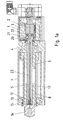
Figur 1 ist ein erfindungsgemäßer Spindelmotor in angeschnittener Schrägansicht und inFigur 1a in Schnittansicht gezeichnet. InFigur 2 und3 sind jeweilige Ausschnitte hiervon vergrößert dargestellt. - Das Motorgehäuse 1 des Elektromotors, umfassend Rotorwelle 2 und Stator 3, ist mit den Gehäuseteilen 4, 7 und 15 des Spindelmotors dicht verbunden. Vorzugswiese ist an jeder Verbindungsschnittstelle der Gehäuseteile ein O-Ring miteingebracht, um Dichtheit auch gegen Überdruck, von mehr als beispielsweise 2 bar zu gewährleisten.
- Das Gehäuseteil 4 nimmt das Lager 18 auf, über welches die Gewindespindel 5 gelagert ist. Diese ist über eine axial steckbare Kupplung mit der Rotorwelle 2 verbunden. Die Kupplung weist ein Klauenteil 20 und ein Klauenteil 22 auf, zwischen denen ein Kunststoffstern 21 angeordnet ist. Vorzugsweise ist diese Wellenkupplung spielfrei.
- Eine im Gehäuseteil 4 angeordneter Dichtung 19 dichtet den Spindelinnenraum gegen den Motor hin ab.
- Somit ist der Innenraum mit Öl befüllbar. Abtriebsseitig ist die Kolbenstange 14 mittels Führungsring 9, Dichtring 10 und Abstreifer 11 abgedichtet gegen die Umgebung.
- Die Dichtungen sind dabei derart gewählt, dass sie gegen Überdrucke von mehr als 2 bar Dichtheit gewährleisten.
- Die Gewindespindel weist eine Schulter 16 auf, die Axialkräfte ableitet an das Lager 18.
- Bei Drehen der Gewindespindel 5 wird die Spindelmutter 5 axial bewegt, weil sie über Führungsteile, wie Führungsteil 25 und Gewindering 26, die mit Linearführvorrichtungen verbunden sind, linear geführt ist.
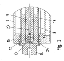
- Zur Abstützkomponente bei besonders langer Ausführung der Gewindespindel 5 ist eine Abstützkomponente 8 aus Teflon vorgesehen, die eine zylindrische Bohrung aufweist zur Aufnahme der Gewindespindel 5 und an ihrem offenen Ende eine Aufweitung aufweist, die in den
Figuren 1 und2 als Einführschräge 17 erkennbar ist. - Die Abstützkomponente 8 ist pressverbunden in der Kolbenstange 14 und verliert den Kontakt zur Gewindespindel 5, wenn die Kolbenstange weit heraus gefahren wird. In diesem Fall ist jedoch auch die Spindelmutter weit verfahren und übernimmt die abstützende Funktion.
- Beim Zurückfahren wird dann die Gewindespindel in die Einführschräge sozusagen eingefädelt.
- Um die Gewindespindel 5 herum ist Schmierstoff vorgesehen, insbesondere Öl.
- Dieses fließt insbesondere bei einer Einbaulage, in welcher die Kolbenstange 14 nach unten zeigt, zum entsprechenden axialen Endbereich. Wird nun der Spindelmotor hin und her gefahren, wird ein Ventil durch auftretenden lokalen Überdruck aktiviert. Hierzu wird die Kugel 12 von der Hülse 13 abgehoben und das Öl fließt durch die Hülse 13 an der Kugel 12 vorbei in die Schmierstoffbohrung 23 und wird bis zur Radialbohrung 30 befördert, wo es dann austritt im Bereich des Lagers 18 und der Dichtung 19.
- Somit ist eine Schmierung in jeder Einbaulage gewährleistet.
- Die geschilderte Ölpumpe ist wirksam, wenn die Kolbenstange nach unten also in Gravitationsrichtung weist. Wenn sie jedoch nach oben weist, fließt das Öl selbsttätig zum Lager 18 und der Dichtung 19.
- Auch in dieser Montagerichtung des Spindelmotors ist wegen der zum Spindelinnraum hin offenen Ausführung des Gewindetriebs eine Schmierung des Gewindetriebs, des Führungsteils und der Nutensteine ausgeführt.
- Die Kugel 12 wird bei Abbau des lokalen Überdrucks durch ein Federelement 24 in ihre Ausgangslage versetzt.
- Das Ölbad verbessert die Wärmeabfuhr, da die Wärme besser aufgespreizt wird und somit die Gehäuseteile gleichmäßiger erwärmt sind vom Inneren her des Spindelmotorbereichs.
- Als Dichtung ist vorzugsweise eine Hochdruckdichtung verwendet, wie beispielsweise eine WCP21 oder MA47.
Claims (15)
- Spindelmotor,
umfassend einen Elektromotor mit einem Rotor, der mit einer Gewindespindel (5) verbunden ist, deren Gewinde mit einem Gewinde einer mit einer Kolbenstange (14) verbundenen Spindelmutter (6) im Eingriff steht,
wobei die Spindelmutter (6) mit Kolbenstange (14) axial geführt ist in einem Gehäuseteil (7) wobei zur axialen Führung ein Führungsteil (25) mit der Spindelmutter (6) und der Kolbenstange (14) verbunden ist,
dadurch gekennzeichnet, dass
in der Kolbenstange (14) eine mit der Kolbenstange (14) verbundene Abstützkomponente (8) für die Gewindespindel (5) derart vorgesehen ist, dass(i) solange die Kolbenstange (14) bis zu einem kritischen Wert herausgefahren ist, die Spindelmutter (6), ein Lager (18) und die Abstützkomponente (8) die Gewindespindel (5) lagern, wobei die Abstützkomponente (8) hierbei das vom Motor abgewandte axiale Ende der Gewindespindel (5) lagert,(ii) und dass bei Überschreiten des kritischen Wertes, also bei den kritischen Wert überschreltendem Herausfahren der Kolbenstange (14), die Gewindespindel (5) nur durch die Spindelmutter (6) und das Lager (18) gelagert ist. - Spindelmotor nach einem der vorangegangenen Ansprüche,
dadurch gekennzeichnet, dass
die Abstützkomponente (8) in die Kolbenstange (14) eingepresst ist. - Spindelmotor nach einem der vorangegangenen Ansprüche,
dadurch gekennzeichnet, dass
die Abstützkomponente (8) eine im Wesentlichen zylindrische Ausnehmung ausgeführt ist, wobei an ihrem offenen Endbereich eine Einführschräge (17) für die Einfädelung der Gewindespindel (5) vorgesehen ist. - Spindelmotor nach einem der vorangegangenen Ansprüche,
dadurch gekennzeichnet, dass
die Abstützkomponente (8) aus PTFE und/oder Teflon ausgeführt ist. - Spindelmotor nach einem der vorangegangenen Ansprüche,
dadurch gekennzeichnet, dass
im Inneren des Spindelmotors, insbesondere im Spindelbereich abtriebsseitig vom Elektromotor das Ölbad vorgesehen ist. - Spindelmotor nach einem der vorangegangenen Ansprüche,
dadurch gekennzeichnet, dass
zumindest eine Hochdruckdichtung zum Abdichten verwendet ist, insbesondere zwischen Spindelbereich und Elektromotor und/oder zwischen Spindelbereich und Umgebung. - Spindelmotor nach einem der vorangegangenen Ansprüche,
dadurch gekennzeichnet, dass
eine Dichtung zwischen dem Raumbereich des Elektromotors und dem Raumbereich, in welchem die Spindelmutter (6) angeordnet ist, vorgesehen ist. - Spindelmotor nach einem der vorangegangenen Ansprüche,
dadurch gekennzeichnet, dass
die Dichtung axial zwischen einem Lager (18) der Gewindespindel (5) und einer die Rotorwelle (2) und die Gewindespindel (5) verbindenden Kupplung angeordnet ist. - Spindelmotor nach einem der vorangegangenen Ansprüche,
dadurch gekennzeichnet, dass
die Kupplung eine axial steckbare Kupplung ist. - Spindelmotor nach einem der vorangegangenen Ansprüche,
dadurch gekennzeichnet, dass
die Dichtung als Wellendichtring ausgeführt ist, der in einem Gehäuseteil seinen Sitz hat, welches auch einen Sitz zur Aufnahme des Lagers (18) der Gewindespindel (5) aufweist,
wobei die Lauffläche des Wellendichtrings an der Gewindespindel (5) vorgesehen ist. - Spindelmotor nach einem der vorangegangenen Ansprüche,
dadurch gekennzeichnet, dass
die Gewindespindel (5) eine Schulter zur Aufnahme von Axialkräften aufweist. - Spindelmotor nach einem der vorangegangenen Ansprüche,
dadurch gekennzeichnet, dass
die Schulter am Innenring des für die Gewindespindel (5) vorgesehenen Lagers (18) abgestützt ist. - Spindelmotor nach einem der vorangegangenen Ansprüche,
dadurch gekennzeichnet, dass
die Kolbenstange (14) abtriebsseitig von einer schmierstoffbetriebenen Dichtungsanordnung abgedichtet ist zum abtriebsseitigen Gehäuseteil hin. - Spindelmotor nach einem der vorangegangenen Ansprüche,
dadurch gekennzeichnet, dass
die Dichtungsanordnung zumindest einen Abstreifer, einen O-Ring und/oder eine Nutdichtung umfasst. - Spindelmotor nach einem der vorangegangenen Ansprüche,
dadurch gekennzeichnet, dass
die Gewindespindel (5) zumindest einen Schmierstoffkanal umfasst, insbesondere einen aus mindestens einer Schmierstoffbohrung zusammengesetzten.
Applications Claiming Priority (2)
| Application Number | Priority Date | Filing Date | Title |
|---|---|---|---|
| DE102007038853 | 2007-08-16 | ||
| PCT/EP2008/005846 WO2009021593A1 (de) | 2007-08-16 | 2008-07-17 | Spindelmotor |
Publications (2)
| Publication Number | Publication Date |
|---|---|
| EP2180976A1 EP2180976A1 (de) | 2010-05-05 |
| EP2180976B1 true EP2180976B1 (de) | 2011-06-15 |
Family
ID=39739549
Family Applications (1)
| Application Number | Title | Priority Date | Filing Date |
|---|---|---|---|
| EP08784829A Active EP2180976B1 (de) | 2007-08-16 | 2008-07-17 | Spindelmotor |
Country Status (4)
| Country | Link |
|---|---|
| EP (1) | EP2180976B1 (de) |
| AT (1) | ATE512755T1 (de) |
| DE (1) | DE102008033600B4 (de) |
| WO (1) | WO2009021593A1 (de) |
Families Citing this family (3)
| Publication number | Priority date | Publication date | Assignee | Title |
|---|---|---|---|---|
| DE102008050993B4 (de) * | 2008-10-13 | 2012-08-30 | Sew-Eurodrive Gmbh & Co. Kg | Spindelmotor |
| DE102009050359B4 (de) | 2009-10-22 | 2013-08-08 | Sew-Eurodrive Gmbh & Co. Kg | Spindelmotor |
| CN108468770A (zh) * | 2018-05-30 | 2018-08-31 | 平湖市祥瑞机械设备制造有限公司 | 一种用于数控设备中丝杆传动机构 |
Family Cites Families (14)
| Publication number | Priority date | Publication date | Assignee | Title |
|---|---|---|---|---|
| GB699778A (en) * | 1951-07-23 | 1953-11-18 | Rotax Ltd | Lubrication of screw jack mechanisms |
| US4232562A (en) * | 1978-11-16 | 1980-11-11 | California Institute Of Technology | Lead screw linear actuator |
| DE3413184A1 (de) | 1984-04-07 | 1985-10-24 | Gildemeister Ag, 4800 Bielefeld | Vorschubantrieb fuer einen auf einem werkzeugmaschinengestell gelagerten schlitten |
| DE4202510A1 (de) * | 1992-01-30 | 1993-08-05 | Schaeffler Waelzlager Kg | Gewindespindel, vorzugsweise fuer eine vorschubeinrichtung einer werkzeugmaschine |
| DE4215098A1 (de) | 1992-05-07 | 1993-11-11 | Roemheld A Gmbh & Co Kg | Spindelantrieb mit Schnellentriegelung der Antriebsspindel |
| JPH0693962A (ja) * | 1992-09-11 | 1994-04-05 | Nippon Muugu Kk | 駆動装置 |
| JPH09331651A (ja) * | 1996-06-07 | 1997-12-22 | Smc Corp | 電動アクチュエータ |
| DE29811566U1 (de) * | 1998-06-29 | 1998-08-20 | Dewert Antriebs Systemtech | Elektromotorischer Möbelantrieb |
| GB0111916D0 (en) * | 2001-05-16 | 2001-07-04 | Prec Actuation Systems Ltd | Improved electromechanical linear actuator |
| DE10235078B4 (de) | 2002-07-31 | 2005-04-28 | Sew Eurodrive Gmbh & Co | Spindelmotor |
| DE102005025748B4 (de) * | 2005-06-02 | 2011-07-28 | Andreas Grasl | Elektrolinearantrieb mit Endabschaltung |
| JP2007089275A (ja) * | 2005-09-21 | 2007-04-05 | Smc Corp | 電動シリンダ |
| DE102007014714B4 (de) * | 2006-04-05 | 2022-11-10 | Sew-Eurodrive Gmbh & Co Kg | Spindelmotor |
| DE102006023516B3 (de) * | 2006-05-19 | 2007-07-12 | Demag Ergotech Gmbh | Elektrische Antriebseinheit für eine Plastifizierschnecke einer Spritzgießmaschine |
-
2008
- 2008-07-17 WO PCT/EP2008/005846 patent/WO2009021593A1/de active Application Filing
- 2008-07-17 AT AT08784829T patent/ATE512755T1/de active
- 2008-07-17 DE DE102008033600.9A patent/DE102008033600B4/de active Active
- 2008-07-17 EP EP08784829A patent/EP2180976B1/de active Active
Also Published As
| Publication number | Publication date |
|---|---|
| EP2180976A1 (de) | 2010-05-05 |
| WO2009021593A1 (de) | 2009-02-19 |
| ATE512755T1 (de) | 2011-07-15 |
| DE102008033600B4 (de) | 2021-02-25 |
| DE102008033600A1 (de) | 2009-03-12 |
Similar Documents
| Publication | Publication Date | Title |
|---|---|---|
| EP2286502B1 (de) | Spindelmotor | |
| DE102009007958C5 (de) | Spindelmotor | |
| DE102009007952B4 (de) | Spindelmotor | |
| EP2180974B1 (de) | Spindelmotor | |
| DE102009050359B4 (de) | Spindelmotor | |
| DE102012006790B4 (de) | Getriebe mit einem ersten und einem zweiten Gehäuseteil | |
| EP2180976B1 (de) | Spindelmotor | |
| EP2180975B1 (de) | Spindelmotor | |
| DE102011003056A1 (de) | Zugmitteltrieb mit einem Spanner und einem Klemmelement | |
| DE19602895B4 (de) | Werkzeug zur Erzeugung einer Lageranordnung für einen Elektromotor | |
| EP3358225B1 (de) | Kompakte getriebemotoranordnung | |
| DE102008050993A1 (de) | Spindelmotor | |
| DE202006019873U1 (de) | Spindelmotor | |
| DE102016112053B4 (de) | Achslagerungseinheit mit Laufring und Förderrolle mit einer Achslagerungseinheit mit Laufring | |
| EP3171028B1 (de) | Mehrstufige kreiselpumpe mit einem axialschub-ausgleichskolben, dessen druck- und saugseiten von einer gleitringdichtung getrennt sind | |
| WO2015018415A1 (de) | Tauchlagerung | |
| DE102008051434A1 (de) | Taumellagerung | |
| DE102015000358B3 (de) | Spindelantrieb mit einem Gehäuse, einer Spindel, und einer mit der Spindel in Wirkverbindung stehenden Spindelmutter | |
| DE112017003444T5 (de) | Statorträger, Turbinensystem, Getriebesystem, Verfahren zur Herstellung eines Statorträgers | |
| DE102008035348B4 (de) | Ölpumpe eines automatisierten Kraftfahrzeug-Getriebes |
Legal Events
| Date | Code | Title | Description |
|---|---|---|---|
| PUAI | Public reference made under article 153(3) epc to a published international application that has entered the european phase |
Free format text: ORIGINAL CODE: 0009012 |
|
| 17P | Request for examination filed |
Effective date: 20100316 |
|
| AK | Designated contracting states |
Kind code of ref document: A1 Designated state(s): AT BE BG CH CY CZ DE DK EE ES FI FR GB GR HR HU IE IS IT LI LT LU LV MC MT NL NO PL PT RO SE SI SK TR |
|
| AX | Request for extension of the european patent |
Extension state: AL BA MK RS |
|
| 17Q | First examination report despatched |
Effective date: 20100629 |
|
| DAX | Request for extension of the european patent (deleted) | ||
| GRAP | Despatch of communication of intention to grant a patent |
Free format text: ORIGINAL CODE: EPIDOSNIGR1 |
|
| GRAS | Grant fee paid |
Free format text: ORIGINAL CODE: EPIDOSNIGR3 |
|
| GRAA | (expected) grant |
Free format text: ORIGINAL CODE: 0009210 |
|
| AK | Designated contracting states |
Kind code of ref document: B1 Designated state(s): AT BE BG CH CY CZ DE DK EE ES FI FR GB GR HR HU IE IS IT LI LT LU LV MC MT NL NO PL PT RO SE SI SK TR |
|
| REG | Reference to a national code |
Ref country code: GB Ref legal event code: FG4D Free format text: NOT ENGLISH Ref country code: CH Ref legal event code: EP |
|
| REG | Reference to a national code |
Ref country code: IE Ref legal event code: FG4D Free format text: LANGUAGE OF EP DOCUMENT: GERMAN |
|
| REG | Reference to a national code |
Ref country code: DE Ref legal event code: R096 Ref document number: 502008003886 Country of ref document: DE Effective date: 20110721 |
|
| REG | Reference to a national code |
Ref country code: NL Ref legal event code: VDEP Effective date: 20110615 |
|
| PG25 | Lapsed in a contracting state [announced via postgrant information from national office to epo] |
Ref country code: NO Free format text: LAPSE BECAUSE OF FAILURE TO SUBMIT A TRANSLATION OF THE DESCRIPTION OR TO PAY THE FEE WITHIN THE PRESCRIBED TIME-LIMIT Effective date: 20110915 Ref country code: LT Free format text: LAPSE BECAUSE OF FAILURE TO SUBMIT A TRANSLATION OF THE DESCRIPTION OR TO PAY THE FEE WITHIN THE PRESCRIBED TIME-LIMIT Effective date: 20110615 Ref country code: HR Free format text: LAPSE BECAUSE OF FAILURE TO SUBMIT A TRANSLATION OF THE DESCRIPTION OR TO PAY THE FEE WITHIN THE PRESCRIBED TIME-LIMIT Effective date: 20110615 Ref country code: SE Free format text: LAPSE BECAUSE OF FAILURE TO SUBMIT A TRANSLATION OF THE DESCRIPTION OR TO PAY THE FEE WITHIN THE PRESCRIBED TIME-LIMIT Effective date: 20110615 |
|
| PG25 | Lapsed in a contracting state [announced via postgrant information from national office to epo] |
Ref country code: FI Free format text: LAPSE BECAUSE OF FAILURE TO SUBMIT A TRANSLATION OF THE DESCRIPTION OR TO PAY THE FEE WITHIN THE PRESCRIBED TIME-LIMIT Effective date: 20110615 Ref country code: LV Free format text: LAPSE BECAUSE OF FAILURE TO SUBMIT A TRANSLATION OF THE DESCRIPTION OR TO PAY THE FEE WITHIN THE PRESCRIBED TIME-LIMIT Effective date: 20110615 Ref country code: GR Free format text: LAPSE BECAUSE OF FAILURE TO SUBMIT A TRANSLATION OF THE DESCRIPTION OR TO PAY THE FEE WITHIN THE PRESCRIBED TIME-LIMIT Effective date: 20110916 Ref country code: CY Free format text: LAPSE BECAUSE OF FAILURE TO SUBMIT A TRANSLATION OF THE DESCRIPTION OR TO PAY THE FEE WITHIN THE PRESCRIBED TIME-LIMIT Effective date: 20110615 Ref country code: SI Free format text: LAPSE BECAUSE OF FAILURE TO SUBMIT A TRANSLATION OF THE DESCRIPTION OR TO PAY THE FEE WITHIN THE PRESCRIBED TIME-LIMIT Effective date: 20110615 |
|
| PG25 | Lapsed in a contracting state [announced via postgrant information from national office to epo] |
Ref country code: MT Free format text: LAPSE BECAUSE OF FAILURE TO SUBMIT A TRANSLATION OF THE DESCRIPTION OR TO PAY THE FEE WITHIN THE PRESCRIBED TIME-LIMIT Effective date: 20110615 Ref country code: NL Free format text: LAPSE BECAUSE OF FAILURE TO SUBMIT A TRANSLATION OF THE DESCRIPTION OR TO PAY THE FEE WITHIN THE PRESCRIBED TIME-LIMIT Effective date: 20110615 |
|
| REG | Reference to a national code |
Ref country code: IE Ref legal event code: FD4D |
|
| BERE | Be: lapsed |
Owner name: SEW-EURODRIVE G.M.B.H. & CO. KG Effective date: 20110731 |
|
| PG25 | Lapsed in a contracting state [announced via postgrant information from national office to epo] |
Ref country code: PT Free format text: LAPSE BECAUSE OF FAILURE TO SUBMIT A TRANSLATION OF THE DESCRIPTION OR TO PAY THE FEE WITHIN THE PRESCRIBED TIME-LIMIT Effective date: 20111017 Ref country code: IE Free format text: LAPSE BECAUSE OF FAILURE TO SUBMIT A TRANSLATION OF THE DESCRIPTION OR TO PAY THE FEE WITHIN THE PRESCRIBED TIME-LIMIT Effective date: 20110615 Ref country code: CZ Free format text: LAPSE BECAUSE OF FAILURE TO SUBMIT A TRANSLATION OF THE DESCRIPTION OR TO PAY THE FEE WITHIN THE PRESCRIBED TIME-LIMIT Effective date: 20110615 Ref country code: IS Free format text: LAPSE BECAUSE OF FAILURE TO SUBMIT A TRANSLATION OF THE DESCRIPTION OR TO PAY THE FEE WITHIN THE PRESCRIBED TIME-LIMIT Effective date: 20111015 Ref country code: EE Free format text: LAPSE BECAUSE OF FAILURE TO SUBMIT A TRANSLATION OF THE DESCRIPTION OR TO PAY THE FEE WITHIN THE PRESCRIBED TIME-LIMIT Effective date: 20110615 |
|
| PG25 | Lapsed in a contracting state [announced via postgrant information from national office to epo] |
Ref country code: RO Free format text: LAPSE BECAUSE OF FAILURE TO SUBMIT A TRANSLATION OF THE DESCRIPTION OR TO PAY THE FEE WITHIN THE PRESCRIBED TIME-LIMIT Effective date: 20110615 Ref country code: PL Free format text: LAPSE BECAUSE OF FAILURE TO SUBMIT A TRANSLATION OF THE DESCRIPTION OR TO PAY THE FEE WITHIN THE PRESCRIBED TIME-LIMIT Effective date: 20110615 Ref country code: MC Free format text: LAPSE BECAUSE OF NON-PAYMENT OF DUE FEES Effective date: 20110731 Ref country code: SK Free format text: LAPSE BECAUSE OF FAILURE TO SUBMIT A TRANSLATION OF THE DESCRIPTION OR TO PAY THE FEE WITHIN THE PRESCRIBED TIME-LIMIT Effective date: 20110615 |
|
| PLBE | No opposition filed within time limit |
Free format text: ORIGINAL CODE: 0009261 |
|
| STAA | Information on the status of an ep patent application or granted ep patent |
Free format text: STATUS: NO OPPOSITION FILED WITHIN TIME LIMIT |
|
| PG25 | Lapsed in a contracting state [announced via postgrant information from national office to epo] |
Ref country code: BE Free format text: LAPSE BECAUSE OF NON-PAYMENT OF DUE FEES Effective date: 20110731 |
|
| 26N | No opposition filed |
Effective date: 20120316 |
|
| PG25 | Lapsed in a contracting state [announced via postgrant information from national office to epo] |
Ref country code: IT Free format text: LAPSE BECAUSE OF FAILURE TO SUBMIT A TRANSLATION OF THE DESCRIPTION OR TO PAY THE FEE WITHIN THE PRESCRIBED TIME-LIMIT Effective date: 20110615 |
|
| PG25 | Lapsed in a contracting state [announced via postgrant information from national office to epo] |
Ref country code: DK Free format text: LAPSE BECAUSE OF FAILURE TO SUBMIT A TRANSLATION OF THE DESCRIPTION OR TO PAY THE FEE WITHIN THE PRESCRIBED TIME-LIMIT Effective date: 20110615 |
|
| REG | Reference to a national code |
Ref country code: DE Ref legal event code: R097 Ref document number: 502008003886 Country of ref document: DE Effective date: 20120316 |
|
| REG | Reference to a national code |
Ref country code: CH Ref legal event code: PL |
|
| PG25 | Lapsed in a contracting state [announced via postgrant information from national office to epo] |
Ref country code: ES Free format text: LAPSE BECAUSE OF FAILURE TO SUBMIT A TRANSLATION OF THE DESCRIPTION OR TO PAY THE FEE WITHIN THE PRESCRIBED TIME-LIMIT Effective date: 20110926 Ref country code: LI Free format text: LAPSE BECAUSE OF NON-PAYMENT OF DUE FEES Effective date: 20120731 Ref country code: CH Free format text: LAPSE BECAUSE OF NON-PAYMENT OF DUE FEES Effective date: 20120731 |
|
| PG25 | Lapsed in a contracting state [announced via postgrant information from national office to epo] |
Ref country code: LU Free format text: LAPSE BECAUSE OF NON-PAYMENT OF DUE FEES Effective date: 20110717 |
|
| PG25 | Lapsed in a contracting state [announced via postgrant information from national office to epo] |
Ref country code: BG Free format text: LAPSE BECAUSE OF FAILURE TO SUBMIT A TRANSLATION OF THE DESCRIPTION OR TO PAY THE FEE WITHIN THE PRESCRIBED TIME-LIMIT Effective date: 20110915 |
|
| PG25 | Lapsed in a contracting state [announced via postgrant information from national office to epo] |
Ref country code: TR Free format text: LAPSE BECAUSE OF FAILURE TO SUBMIT A TRANSLATION OF THE DESCRIPTION OR TO PAY THE FEE WITHIN THE PRESCRIBED TIME-LIMIT Effective date: 20110615 |
|
| PG25 | Lapsed in a contracting state [announced via postgrant information from national office to epo] |
Ref country code: HU Free format text: LAPSE BECAUSE OF FAILURE TO SUBMIT A TRANSLATION OF THE DESCRIPTION OR TO PAY THE FEE WITHIN THE PRESCRIBED TIME-LIMIT Effective date: 20110615 |
|
| REG | Reference to a national code |
Ref country code: AT Ref legal event code: MM01 Ref document number: 512755 Country of ref document: AT Kind code of ref document: T Effective date: 20130717 |
|
| PG25 | Lapsed in a contracting state [announced via postgrant information from national office to epo] |
Ref country code: AT Free format text: LAPSE BECAUSE OF NON-PAYMENT OF DUE FEES Effective date: 20130717 |
|
| REG | Reference to a national code |
Ref country code: FR Ref legal event code: PLFP Year of fee payment: 9 |
|
| REG | Reference to a national code |
Ref country code: FR Ref legal event code: PLFP Year of fee payment: 10 |
|
| REG | Reference to a national code |
Ref country code: FR Ref legal event code: PLFP Year of fee payment: 11 |
|
| PGFP | Annual fee paid to national office [announced via postgrant information from national office to epo] |
Ref country code: FR Payment date: 20230608 Year of fee payment: 16 |
|
| PGFP | Annual fee paid to national office [announced via postgrant information from national office to epo] |
Ref country code: GB Payment date: 20230601 Year of fee payment: 16 |
|
| PGFP | Annual fee paid to national office [announced via postgrant information from national office to epo] |
Ref country code: DE Payment date: 20230731 Year of fee payment: 16 |