EP2180433A2 - Verfahren zur Herstellung eines tragbaren Datenträgers und damit hergestellter tragbarer Datenträger - Google Patents
Verfahren zur Herstellung eines tragbaren Datenträgers und damit hergestellter tragbarer Datenträger Download PDFInfo
- Publication number
- EP2180433A2 EP2180433A2 EP09013348A EP09013348A EP2180433A2 EP 2180433 A2 EP2180433 A2 EP 2180433A2 EP 09013348 A EP09013348 A EP 09013348A EP 09013348 A EP09013348 A EP 09013348A EP 2180433 A2 EP2180433 A2 EP 2180433A2
- Authority
- EP
- European Patent Office
- Prior art keywords
- component
- data carrier
- adhesive
- portable data
- limiting means
- Prior art date
- Legal status (The legal status is an assumption and is not a legal conclusion. Google has not performed a legal analysis and makes no representation as to the accuracy of the status listed.)
- Granted
Links
Images


Classifications
-
- B—PERFORMING OPERATIONS; TRANSPORTING
- B32—LAYERED PRODUCTS
- B32B—LAYERED PRODUCTS, i.e. PRODUCTS BUILT-UP OF STRATA OF FLAT OR NON-FLAT, e.g. CELLULAR OR HONEYCOMB, FORM
- B32B37/00—Methods or apparatus for laminating, e.g. by curing or by ultrasonic bonding
- B32B37/14—Methods or apparatus for laminating, e.g. by curing or by ultrasonic bonding characterised by the properties of the layers
- B32B37/16—Methods or apparatus for laminating, e.g. by curing or by ultrasonic bonding characterised by the properties of the layers with all layers existing as coherent layers before laminating
- B32B37/18—Methods or apparatus for laminating, e.g. by curing or by ultrasonic bonding characterised by the properties of the layers with all layers existing as coherent layers before laminating involving the assembly of discrete sheets or panels only
- B32B37/182—Methods or apparatus for laminating, e.g. by curing or by ultrasonic bonding characterised by the properties of the layers with all layers existing as coherent layers before laminating involving the assembly of discrete sheets or panels only one or more of the layers being plastic
- B32B37/185—Laminating sheets, panels or inserts between two discrete plastic layers
-
- G—PHYSICS
- G06—COMPUTING OR CALCULATING; COUNTING
- G06K—GRAPHICAL DATA READING; PRESENTATION OF DATA; RECORD CARRIERS; HANDLING RECORD CARRIERS
- G06K19/00—Record carriers for use with machines and with at least a part designed to carry digital markings
- G06K19/06—Record carriers for use with machines and with at least a part designed to carry digital markings characterised by the kind of the digital marking, e.g. shape, nature, code
- G06K19/067—Record carriers with conductive marks, printed circuits or semiconductor circuit elements, e.g. credit or identity cards also with resonating or responding marks without active components
- G06K19/07—Record carriers with conductive marks, printed circuits or semiconductor circuit elements, e.g. credit or identity cards also with resonating or responding marks without active components with integrated circuit chips
- G06K19/073—Special arrangements for circuits, e.g. for protecting identification code in memory
- G06K19/07309—Means for preventing undesired reading or writing from or onto record carriers
- G06K19/07345—Means for preventing undesired reading or writing from or onto record carriers by activating or deactivating at least a part of the circuit on the record carrier, e.g. ON/OFF switches
-
- G—PHYSICS
- G06—COMPUTING OR CALCULATING; COUNTING
- G06K—GRAPHICAL DATA READING; PRESENTATION OF DATA; RECORD CARRIERS; HANDLING RECORD CARRIERS
- G06K19/00—Record carriers for use with machines and with at least a part designed to carry digital markings
- G06K19/06—Record carriers for use with machines and with at least a part designed to carry digital markings characterised by the kind of the digital marking, e.g. shape, nature, code
- G06K19/067—Record carriers with conductive marks, printed circuits or semiconductor circuit elements, e.g. credit or identity cards also with resonating or responding marks without active components
- G06K19/07—Record carriers with conductive marks, printed circuits or semiconductor circuit elements, e.g. credit or identity cards also with resonating or responding marks without active components with integrated circuit chips
- G06K19/077—Constructional details, e.g. mounting of circuits in the carrier
-
- B—PERFORMING OPERATIONS; TRANSPORTING
- B32—LAYERED PRODUCTS
- B32B—LAYERED PRODUCTS, i.e. PRODUCTS BUILT-UP OF STRATA OF FLAT OR NON-FLAT, e.g. CELLULAR OR HONEYCOMB, FORM
- B32B2457/00—Electrical equipment
Definitions
- the invention relates to a method for producing a portable data carrier having at least one electronic circuit, a mechanically sensitive component and a body accommodating the electronic circuit and the component, wherein the body is produced by H synthlamination of plastic parts.
- the invention further relates to a portable data storage medium for storing and / or processing data, comprising an electronic circuit, a component, in particular a switching device operable from outside the portable data carrier, and a body accommodating the electronic circuit and the switching device, which are formed by hot-laminated plastic parts becomes.
- a portable data carrier As part of the manufacturing process for a portable data carrier is a common practice is to completely or partially surround an electronic circuit with a material, in particular with a plastic material.
- the electronic circuit is usually an integrated circuit, in particular a microcontroller.
- the portable data carriers are each equipped in addition to the electronic circuit with other components, in particular with one or more switching devices. Due to their flat design and low production costs are suitable for this purpose membrane key or domes particularly well.
- the method according to the invention relates to the production of a portable data carrier which has at least one electronic circuit, a mechanically sensitive component and a body accommodating the electronic circuit and the component, wherein the body is produced by lamination of plastic parts.
- the component is applied to a bottom of the body and surrounded by a protective space for the component forming limiting means, wherein the limiting means during the subsequent lamination of the plastic parts prevents the penetration of adhesive or other flowable material into the shelter.
- the actuatable from outside the portable data carrier switching device may be formed as a mechanical button or as an elastically deformable element.
- the component can be integrated in the form of a snap disk protected in the card body. Snap discs are known to close by pressure activation an electronic circuit and trigger a corresponding functional application. While an unprotected snap-action disc in the card body gives no or almost no tactile feedback, the tactile feedback of such a snap-action disc can be completely retained by providing a protective space according to the invention.
- the lamination-related impairment without special protective measures is due to the fact that the individual foil layers of the body flow together during lamination around the snap disc and thus reduce the freedom of movement of the snap disc. By the integrated in the card body shelter for the snap disk, this can be prevented, so that the tactility of the snap disk is maintained.
- the limiting means is formed by an adhesive bead surrounding the component and spaced from the component.
- an adhesive is advantageous because it can be processed in a simple manner. It is provided that the bead of adhesive is applied to the floor in such a way that it circulates uninterrupted and closed the component. In this way it is ensured that no adhesive or other flowable material can reach the inside of the shelter during lamination.
- the bead of adhesive is applied to the floor in such a way that it protrudes beyond the end of the floor facing away from the bottom.
- a protective plate with high rigidity is applied to the limiting means, such that the shelter is closed by the protective plate. It is preferred in this case if a curing of the composite of the rigid protective plate and the bead of adhesive takes place. This ensures that the rigid protective plate can not be displaced relative to the bead of adhesive during lamination. As a result, the shelter formed by the bead of adhesive and the protective plate can be maintained even under unfavorable conditions. The component located in the interior of the shelter is protected against the aforementioned adhesives or flowable materials.
- the protective plate for the mechanical actuation of the component is elastically deformable.
- the protective plate can be preserved after production of the entire portable data carrier.
- the actuation of the as Button or snap disk formed component then takes place through the protective plate.
- an adhesive film is applied to the formation of the shelter over the component and formed with a tool under temperature exposure. It is expedient here if the tool has a shape corresponding to the shape of the component, so that the adhesive film can be applied precisely over the component.
- the adhesive film is stiffened in the region of the component at least in sections before application to the component fastened to the floor with a temperature-resistant material. As a result, the mechanical stability of the constructed protection chamber is ensured. It is also expedient if the adhesive film is stiffened on the component side facing the temperature-resistant material. As a result, a bonding of the component with the adhesive film and thus a functional impairment is prevented. As a result, a proper operation of the component after production of the portable data carrier can be ensured.
- the shelter for the component After the formation of the shelter for the component is provided to apply the plastic parts of the body to the semifinished product and in particular to laminate hot.
- the introduction of the mechanically sensitive component during the manufacture of the portable data carrier can thus take place from several layers, whereby a simpler and more efficient production is ensured.
- the invention further provides a portable data storage medium for storing and / or processing data, comprising an electronic circuit, a component, in particular a switching device operable from outside the portable data carrier, and a body accommodating the electronic circuit and the switching device, formed by laminated plastic parts becomes.
- the portable data carrier is characterized in that the component is surrounded by a protective space providing a limiting means which prevents the subsequent lamination of the plastic parts, the introduction of adhesive or other flowable material in the shelter.
- the portable data carrier according to the invention e.g. a display card
- a display card has the advantage of a simple and inexpensive production.
- sensitive mechanical components such as e.g. Buttons in the form of snap discs, are integrated during the production of the card body in this.
- the data carrier is characterized in an embodiment variant in that the limiting means is formed by an encircling the component and spaced from the component Klebstoffwulst.
- the bead of adhesive is applied to the floor in such a way that it circulates uninterrupted and closed the component, whereby the mechanical component to be protected is optimally protected from adhesive or flowable materials during manufacture.
- the bead of adhesive is applied to the floor in such a way that it protrudes beyond the end of the component facing away from the bottom, a protective panel with high rigidity acting on the limiting means is applied such that the shelter is closed by the protective plate.
- an adhesive film is applied to the formation of the shelter over the component and formed with a tool under temperature exposure.
- the adhesive film is stiffened in the region of the component with a temperature-resistant material.
- the adhesive film is stiffened on the component side facing the temperature-resistant material.
- Fig.1 shows a schematic cross-sectional view of a portable data carrier 1 according to the invention according to a first embodiment variant.
- a mechanically sensitive component 2 is applied on a bottom 4, a mechanically sensitive component 2 is applied.
- the base 4 is part of a subsequently produced body 3 of the data carrier 1.
- the component 2 may represent, for example, an operable from outside of the data carrier 1 switching device.
- the component may be formed by a snap-action disk which passes through Pressure activation closes an electronic circuit not shown in detail in the figure and can trigger a corresponding functional application.
- a circumferential bead of adhesive 7 is formed as a limiting means 6, which rotates the component 2 without interruption and closed.
- the adhesive bead 7 represents a limiting means 6 for forming the protective space 5 and is formed in particular by an adhesive system.
- a UV adhesive or a one- or multi-component adhesive system can be used.
- the closed bead of adhesive may be annular or circular around the component. In this case, the bead of adhesive 7 is applied to the floor 4 such that it protrudes beyond the end of the component 2 facing away from the bottom.
- a protective plate is applied with high rigidity, so that within the adhesive bead 7 and the protective plate 8, a shelter 5 is formed for the applied to the bottom 4 component 2. Between the protective plate 8 and the component 2 can, as in Fig.1 shown schematically, a distance remain. Likewise, the dimensioning of adhesive bead 7 and component 2 may be such that the protective plate 8 directly adjoins the component 2.
- an adhesive film 10 is positioned over the applied on the bottom 4 mechanically sensitive component 2, wherein the bottom 4 is in turn part of a manufactured body 3 of the data carrier.
- a stiffening layer 11 is provided from a temperature-resistant material.
- This prepared adhesive film 10 is applied via a heating die 12, which has a recess 13 (negative mold) adapted to the shape of the component 2, via the component 2. After the application of the adhesive film 10, it is expedient to provide a curing step.
- the stiffening layer 11 serving as the limiting means 6 provides a protective space 5 for the component 2, by which, as in the preceding embodiment, prevents adhesive or other flowable materials from reaching or into the region of the component by further manufacturing steps of the portable data carrier and affect its functionality.
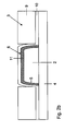
- Fig. 2a schematically illustrates the situation before the provided with the stiffening layer 11 adhesive film 10 is applied over the mechanical component 2
- Fig. 2b the situation after the application of the adhesive film 10.
- the applied after production of this semi-finished or applied laminated plastic parts 9 are shown, which is approximately flush with the component 2 or the applied adhesive film 10 and form together with the bottom 4, the body 3.
- a cover layer (not shown) may be further provided.
- the proposed method is suitable for the production of portable data carriers, in which mechanically sensitive components must be integrated into the card body.
- the invention provides for a protective space to be formed around the sensitive components before further plastic parts of the body of the portable data carrier are applied to the prepared semifinished product and laminated.
Landscapes
- Engineering & Computer Science (AREA)
- Computer Hardware Design (AREA)
- Microelectronics & Electronic Packaging (AREA)
- Physics & Mathematics (AREA)
- General Physics & Mathematics (AREA)
- Theoretical Computer Science (AREA)
- Computer Security & Cryptography (AREA)
- General Engineering & Computer Science (AREA)
- Credit Cards Or The Like (AREA)
Abstract
Description
- Die Erfindung betrifft ein Verfahren zur Herstellung eines tragbaren Datenträgers, der zumindest eine elektronische Schaltung, ein mechanisch empfindliches Bauteil und einen die elektronische Schaltung und das Bauteil aufnehmenden Körper aufweist, wobei der Körper durch Heißlamination von Kunststoffteilen hergestellt wird. Die Erfindung betrifft ferner einen tragbaren Datenträger zur Speicherung und/ oder Verarbeitung von Daten, mit einer elektronischen Schaltung, einem Bauteil, insbesondere einer von außerhalb des tragbaren Datenträgers betätigbaren Schalteinrichtung, und einen die elektronische Schaltung und die Schalteinrichtung aufnehmenden Körper, der durch heißlaminierte Kunststoffteile gebildet wird.
- Im Rahmen des Herstellungsprozesses für einen tragbaren Datenträger besteht eine übliche Vorgehensweise darin, eine elektronische Schaltung ganz oder teilweise mit einem Material, insbesondere mit einem Kunststoffmaterial, zu umgeben. Bei der elektronischen Schaltung handelt es sich in der Regel um einen integrierten Schaltkreis, insbesondere um einen Mikrocontroller. Je nach dem Anwendungsgebiet, für das die tragbaren Datenträger vorgesehen sind, werden die tragbaren Datenträger jeweils zusätzlich zur elektronischen Schaltung mit weiteren Komponenten ausgestattet, insbesondere auch mit einer oder mehreren Schalteinrichtungen. Aufgrund ihrer flachen Bauweise und der niedrigen Herstellungskosten eignen sich für diesen Zweck Folientaster oder Schnappscheiben besonders gut.
- Als problematisch hat sich erwiesen, dass derartige Schalteinrichtungen beim Laminieren so nachhaltig in den Kunststoffkartenkörper eingebettet werden, dass die charakteristische taktile Rückmeldung beim Betätigen beeinträchtigt wird. Die Heißlamination wird aber gerade bei der Herstellung von tragbaren Datenträgern, insbesondere von Chipkarten, häufig eingesetzt, da sich damit eine untrennbare Verbindung der bei der Herstellung verwendeten Folien erzielen lässt.
- Zur Vermeidung einer Funktionsbeeinträchtigung aufgrund einer Heißlamination ist es aus der
DE 10 2005 020 092 A1 bekannt, einen in Gestalt einer Schnappscheibe ausgebildeten Taster in eine in dem Kartenkörper vorbereitete Kavität einzusetzen. Dabei wird die Kavität nach Herstellung des Kartenkörpers in diesen eingearbeitet. Eine konstruktiv ähnliche Variante ist aus derWO 2005/062245 aus den Fig. 7 bis 9 entnehmbar. - Ferner ist es aus der
FR 2 757 313 - Es ist Aufgabe der vorliegenden Erfindung, ein Verfahren zur Herstellung eines tragbaren Datenträgers anzugeben, bei welchem das Herstellungsverfahren optimiert gestaltbar ist und bei dem auch der Einsatz von Material erweichenden Fertigungstechniken zur Herstellung des tragbaren Datenträgers ermöglicht ist. Ferner soll ein tragbarer Datenträger angegeben werden.
- Diese Aufgaben werden gelöst durch ein Verfahren mit den Merkmalen des Patentanspruches 1 sowie einen tragbaren Datenträger mit den Merkmalen des Patentanspruches 14. Vorteilhafte Ausgestaltungen ergeben sich aus den abhängigen Patentansprüchen.
- Das erfindungsgemäße Verfahren bezieht sich auf die Herstellung eines tragbaren Datenträgers, der zumindest eine elektronische Schaltung, ein mechanisch empfindliches Bauteil und einen die elektronische Schaltung und das Bauteil aufnehmenden Körper aufweist, wobei der Körper durch Lamination von Kunststoffteilen hergestellt wird. Erfindungsgemäß ist vorgesehen, dass das Bauteil auf einen Boden des Körpers aufgebracht und von einem einen Schutzraum für das Bauteil ausbildenden Begrenzungsmittel umgeben ist, wobei das Begrenzungsmittel während der nachfolgenden Lamination der Kunststoffteile das Eindringen von Klebstoff oder einem anderen fließfähigen Material in den Schutzraum verhindert.
- Durch das erfindungsgemäße Verfahren können laminierbedingte Beeinträchtigungen vermieden werden. Insbesondere ist es möglich, dass als Bauteil eine von außerhalb des tragbaren Datenträgers betätigbare Schalteinrichtung in dem Schutzraum angeordnet wird.
- Die von außerhalb des tragbaren Datenträgers betätigbare Schalteinrichtung kann als mechanischer Taster oder als elastisch deformierbares Element ausgebildet sein. Insbesondere kann das Bauteil in Gestalt einer Schnappscheibe geschützt in den Kartenkörper integriert werden. Schnappscheiben schließen bekanntermaßen durch Druckaktivierung einen elektronischen Schaltkreis und lösen eine entsprechende Funktionsanwendung aus. Während eine ungeschützte Schnappscheibe im Kartenkörper keine bzw. fast keine taktile Rückmeldung gibt, kann durch die Bereitstellung eines erfindungsgemäßen Schutzraumes die taktile Rückmeldung einer derartigen Schnappscheibe vollständig erhalten bleiben. Die laminierbedingte Beeinträchtigung ohne besondere Schutzmaßnahmen ist darauf zurückzuführen, dass die einzelnen Folienschichten des Körpers bei der Laminierung um die Schnappscheibe zusammenfließen und somit die Bewegungsfreiheit der Schnappscheibe verringern. Durch den in dem Kartenkörper integrierten Schutzraum für die Schnappscheibe kann dies verhindert werden, so dass die Taktilität der Schnappscheibe erhalten bleibt.
- In einer ersten Ausgestaltungsvariante wird das Begrenzungsmittel durch einen das Bauteil umlaufenden und zu dem Bauteil beabstandeten Klebstoffwulst ausgebildet. Die Verwendung eines Klebstoffs ist vorteilhaft, da dieser auf einfache Weise verarbeitbar ist. Dabei ist vorgesehen, dass der Klebstoffwulst derart auf den Boden aufgebracht wird, dass dieser unterbrechungsfrei und geschlossen das Bauteil umläuft. Auf diese Weise ist sichergestellt, dass kein Klebstoff oder anderes fließfähiges Material während des Laminierens in das Innere des Schutzraums gelangen kann.
- Zweckmäßigerweise wird der Klebstoffwulst derart auf den Boden aufgebracht, dass dieser über das von dem Boden abgewandte Ende des Bodens hinausragt. Dabei wird eine Schutzplatte mit hoher Steifigkeit auf das Begrenzungsmittel aufgebracht, derart, dass der Schutzraum durch die Schutzplatte geschlossen wird. Es ist hierbei bevorzugt, wenn eine Aushärtung des Verbunds aus der steifen Schutzplatte und dem Klebstoffwulst erfolgt. Hierdurch ist sichergestellt, dass die steife Schutzplatte nicht relativ zu dem Klebstoffwulst während des Laminierens verschoben werden kann. Dadurch kann der durch den Klebstoffwulst und die Schutzplatte gebildete Schutzraum auch unter ungünstigen Bedingungen erhalten bleiben. Das im Inneren des Schutzraums befindliche Bauteil wird dabei gegen die bereits erwähnten Klebstoffe bzw. fließfähigen Materialien geschützt.
- Insbesondere ist die Schutzplatte zur mechanischen Betätigung des Bauteils elastisch deformierbar. Die Schutzplatte kann dabei nach Herstellung des gesamten tragbaren Datenträgers erhalten bleiben. Die Betätigung des als Taster oder Schnappscheibe ausgebildeten Bauteils erfolgt dann durch die Schutzplatte hindurch.
- In einer anderen Ausgestaltung wird zur Ausbildung des Schutzraums über das Bauteil eine Klebstofffolie aufgebracht und mit einem Werkzeug unter Temperaturbeaufschlagung umgeformt. Hierbei ist es zweckmäßig, wenn das Werkzeug eine zu der Gestalt des Bauteils korrespondierende Form aufweist, so dass die Klebstofffolie passgenau über das Bauteil aufgebracht werden kann.
- Es ist hierbei zweckmäßig, wenn die Klebstofffolie im Bereich des Bauteils zumindest abschnittsweise vor dem Aufbringen auf das auf dem Boden befestigte Bauteil mit einem temperaturbeständigen Material versteift wird. Hierdurch wird die mechanische Stabilität der aufgebauten Schutzkammer gewährleistet. Dabei ist es weiterhin zweckmäßig, wenn die Klebstofffolie auf der dem Bauteil zugewandten Seite mit dem temperaturbeständigen Material versteift wird. Hierdurch wird eine Verklebung des Bauteils mit der Klebstofffolie und damit eine Funktionsbeeinträchtigung verhindert. Dadurch kann eine einwandfreie Betätigung des Bauteils nach Herstellung des tragbaren Datenträgers sichergestellt werden.
- Nach der Ausbildung des Schutzraums für das Bauteil ist vorgesehen, die Kunststoffteile des Körpers auf das Halbzeug aufzubringen und insbesondere heiß zu laminieren. Im Gegensatz zum Stand der Technik kann damit die Einbringung des mechanisch empfindlichen Bauteils während der Fertigung des tragbaren Datenträgers aus mehreren Schichten erfolgen, wodurch eine einfachere und effizientere Fertigung gewährleistet ist.
- Die Erfindung schafft weiterhin einen tragbaren Datenträger zur Speicherung und/ oder Verarbeitung von Daten, mit einer elektronischen Schaltung, einem Bauteil, insbesondere einer von außerhalb des tragbaren Datenträgers betätigbaren Schalteinrichtung, und einem die elektronische Schaltung und die Schalteinrichtung aufnehmenden Körper, der durch laminierte Kunststoffteile gebildet wird. Der tragbare Datenträger zeichnet sich dadurch aus, dass das Bauteil von einem einen Schutzraum bereitstellenden Begrenzungsmittel umgeben ist, welches während der nachfolgenden Lamination der Kunststoffteile das Einbringen von Klebstoff oder einem anderen fließfähigen Material in den Schutzraum verhindert.
- Der erfindungsgemäße tragbare Datenträger, z.B. eine Displaykarte, weist den Vorteil einer einfachen und kostengünstigen Herstellung auf. Insbesondere können empfindliche mechanische Bauteile, wie z.B. Taster in Gestalt von Schnappscheiben, während der Herstellung des Kartenkörpers in diesen integriert werden.
- Der Datenträger zeichnet sich in einer Ausgestaltungsvariante dadurch aus, dass das Begrenzungsmittel durch einen das Bauteil umlaufenden und zu dem Bauteil beabstandeten Klebstoffwulst ausgebildet ist. Insbesondere ist der Klebstoffwulst derart auf den Boden aufgebracht, dass dieser unterbrechungsfrei und geschlossen das Bauteil umläuft, wodurch das zu schützende mechanische Bauteil während der Herstellung optimal vor Klebstoff oder fließfähigen Materialien geschützt ist.
- Zweckmäßigerweise ist der Klebstoffwulst derart auf den Boden aufgebracht, dass dieser über das von dem Boden abgewandte Ende des Bauteils hinausragt, wobei eine Schutzplatte mit hoher Steifigkeit auf das Begrenzungsmittel derart aufgebracht ist, dass der Schutzraum durch die Schutzplatte geschlossen ist.
- In einer anderen Ausgestaltung ist zur Ausbildung des Schutzraums über das Bauteil eine Klebstofffolie aufgebracht und mit einem Werkzeug unter Temperaturbeaufschlagung umgeformt. Zweckmäßigerweise ist die Klebstofffolie im Bereich des Bauteils mit einem temperaturbeständigen Material versteift. Insbesondere ist die Klebstofffolie auf der dem Bauteil zugewandten Seite mit dem temperaturbeständigen Material versteift.
- Die Erfindung wird nachfolgend näher anhand zweier Ausführungsbeispiele in den Figuren beschrieben. Es zeigen:
- Fig.1
- eine erste schematische Querschnittsdarstellung eines erfindungsgemäßen tragbaren Datenträgers gemäß einer ersten Ausgestaltungsvariante, und
- Fig. 2a und 2b
- eine schematische Querschnittsdarstellung eines erfindungsgemäßen tragbaren Datenträgers gemäß einer zweiten Ausführungsvariante in zwei unterschiedlichen Herstellungsstufen.
-
Fig.1 zeigt in einer schematischen Querschnittsdarstellung einen erfindungsgemäßen tragbaren Datenträger 1 gemäß einer ersten Ausführungsvariante. Auf einem Boden 4 ist ein mechanisch empfindliches Bauteil 2 aufgebracht. Der Boden 4 ist Bestandteil eines im Weiteren herzustellenden Körpers 3 des Datenträgers 1. Das Bauteil 2 kann beispielsweise eine von außerhalb des Datenträgers 1 betätigbare Schalteinrichtung darstellen. Insbesondere kann das Bauteil durch eine Schnappscheibe gebildet sein, welche durch Druckaktivierung einen in der Figur nicht näher dargestellten elektronischen Schaltkreis schließt und eine entsprechende Funktionsanwendung auslösen kann. - Um das Bauteil 2 herum und zu diesem beabstandet ist als Begrenzungsmittel 6 ein umlaufender Klebstoffwulst 7 ausgebildet, der das Bauteil 2 unterbrechungsfrei und geschlossen umläuft. Der Klebstoffwulst 7 stellt ein Begrenzungsmittel 6 zur Ausbildung des Schutzraums 5 dar und ist insbesondere durch ein Klebstoffsystem gebildet. Insbesondere kann ein UV-Klebstoff oder ein ein- oder mehrkomponentiges Klebstoffsystem verwendet werden. Der geschlossene Klebstoffwulst kann ringförmig oder kreisförmig um das Bauteil herum ausgebildet sein. Dabei ist der Klebstoffwulst 7 derart auf dem Boden 4 aufgebracht, dass dieser über das von dem Boden abgewandte Ende des Bauteils 2 hinausragt. Auf dem Klebstoffwulst 7 ist eine Schutzplatte mit hoher Steifigkeit aufgebracht, so dass innerhalb des Klebstoffwulstes 7 und der Schutzplatte 8 ein Schutzraum 5 für das auf dem Boden 4 aufgebrachte Bauteil 2 gebildet ist. Zwischen der Schutzplatte 8 und dem Bauteil 2 kann, wie in
Fig.1 schematisch dargestellt, ein Abstand verbleiben. Ebenso kann die Dimensionierung von Klebstoffwulst 7 und Bauteil 2 derart sein, dass die Schutzplatte 8 unmittelbar an das Bauteil 2 grenzt. - Nach dem Aufbringen der Schutzplatte 8 auf dem Klebstoffwulst 7 zur Abschirmung des auf dem Boden 4 aufgebrachten Bauteils 2 erfolgt zweckmäßigerweise ein Aushärteschritt, so dass die Schutzplatte 8 nicht mehr von dem Klebstoffwulst 7 gelöst werden kann und der Schutzraum 5 eine ausreichend hohe Steifigkeit für die nachfolgenden Herstellungsschritte aufweist. Nach der Ausbildung des beschriebenen Schutzraumes 5 für das Bauteil 2 werden ein oder mehrere Kunststoffteile 9 des Körpers 3 des tragbaren Datenträgers 1 auf das beschriebene Halbzeug aufgebracht und laminiert. Dabei ist sichergestellt, dass, bedingt durch die Lamination, kein Klebstoff oder anderes fließfähiges Material in das Innere des Schutzraumes 5 und damit an das Bauteil 2 gelangen kann. Fließfähige Materialien werden durch den Klebstoffwulst 7 gebremst bzw. gestoppt.
- Gemäß einer zweiten Variante, welche in den
Fig. 2a undFig. 2b schematisch in zwei unterschiedlichen Herstellungsstufen dargestellt ist, wird über das auf dem Boden 4 aufgebrachte mechanisch empfindliche Bauteil 2 eine Klebefolie 10 positioniert, wobei der Boden 4 wiederum Bestandteil eines herzustellenden Körpers 3 des Datenträgers ist. Auf der dem Bauteil 2 zugewandten Seite der Klebefolie 10 ist eine Versteifungsschicht 11 aus einem temperaturbeständigen Material vorgesehen. Diese vorbereitete Klebstofffolie 10 wird über einen Heizstempel 12, der eine an die Gestalt des Bauteils 2 angepasst Aussparung 13 (Negativform) aufweist, über das Bauteil 2 appliziert. Nach dem Aufbringen der Klebstofffolie 10 ist es zweckmäßig, einen Aushärteschritt vorzusehen. - Die als Begrenzungsmittel 6 dienende Versteifungsschicht 11 stellt einen Schutzraum 5 für das Bauteil 2 bereit, durch welchen, wie im vorangegangenen Ausführungsbeispiel, verhindert wird, dass durch weitere Herstellungsschritte des tragbaren Datenträgers Klebstoff oder andere fließfähige Materialien an das oder in den Bereich des Bauteils gelangen und dessen Funktionsfähigkeit beeinflussen.
- Während
Fig. 2a die Situation schematisch darstellt, bevor die mit der Versteifungsschicht 11 versehene Klebstofffolie 10 über das mechanische Bauteil 2 appliziert wird, zeigtFig. 2b die Situation nach dem Applizieren der Klebstofffolie 10. Ferner sind die nach Herstellung dieses Halbzeugs aufgebrachte oder aufgebrachten laminierten Kunststoffteile 9 dargestellt, welche in etwa bündig mit dem Bauteil 2 bzw. der darüber aufgebrachten Klebefolie 10 abschließen und zusammen mit dem Boden 4 den Körper 3 ausbilden. Als oberste Schicht des Körpers 3 kann ferner eine (nicht dargestellte) Deckschicht vorgesehen sein. - Das vorgeschlagene Verfahren eignet sich für die Herstellung tragbarer Datenträger, bei denen mechanisch empfindliche Bauteile in den Kartenkörper integriert werden müssen. Hierzu sieht die Erfindung vor, einen Schutzraum um die empfindlichen Bauelemente auszubilden, bevor weitere Kunststoffteile des Körpers des tragbaren Datenträgers auf das vorbereitete Halbzeug aufgebracht und laminiert werden.
Claims (15)
- Verfahren zur Herstellung eines tragbaren Datenträgers (1), der zumindest eine elektronische Schaltung, ein mechanisch empfindliches Bauteil (2) und einen die elektronische Schaltung und das Bauteil (2) aufnehmenden Körper (3) aufweist, wobei der Körper (3) durch Lamination von Kunststoffteilen (9) hergestellt wird, dadurch gekennzeichnet, dass das Bauteil (2) auf einen Boden (4) des Körpers (3) aufgebracht und von einem einen Schutzraum (5) für das Bauteil (2) ausbildenden Begrenzungsmittel (6) umgeben wird, wobei das Begrenzungsmittel (6) während der nachfolgenden Lamination der Kunststoffteile (9) das Eindringen von Klebstoff oder einem anderen fließfähigen Material in den Schutzraum (5) verhindert.
- Verfahren nach Anspruch 1, dadurch gekennzeichnet, dass als Bauteil (2) eine von außerhalb des tragbaren Datenträgers (1) betätigbare Schalteinrichtung in dem Schutzraum (5) angeordnet wird.
- Verfahren nach einem der vorherigen Ansprüche, dadurch gekennzeichnet, dass das Begrenzungsmittel (6) durch einen das Bauteil (2) umlaufenden und zu dem Bauteil (2) beabstandeten Klebstoffwulst (7) ausgebildet wird.
- Verfahren nach Anspruch 3, dadurch gekennzeichnet, dass der Klebstoffwulst (7) derart auf den Boden (4) aufgebracht wird, dass dieser unterbrechungsfrei und geschlossen das Bauteil (2) umläuft.
- Verfahren nach Anspruch 3 oder 4, dadurch gekennzeichnet, dass der Klebstoffwulst (7) derart auf den Boden (4) aufgebracht wird, dass dieser über das von dem Boden (4) abgewandte Ende des Bauteils (2) hinausragt und wobei eine Schutzplatte (8) mit hoher Steifigkeit auf das Begrenzungsmittel (6) aufgebracht wird, derart, dass der Schutzraum (5) durch die Schutzplatte (8) geschlossen wird.
- Verfahren nach Anspruch 5, dadurch gekennzeichnet, dass eine Aushärtung des Verbunds aus der steifen Schutzplatte (8) und dem Klebstoffwulst (7) erfolgt.
- Verfahren nach Anspruch 5 oder 6, dadurch gekennzeichnet, dass die Schutzplatte (8) zur mechanischen Betätigung des Bauteils (2) elastisch deformierbar ist.
- Verfahren nach einem der Ansprüche 1 oder 2, dadurch gekennzeichnet, dass zur Ausbildung des Schutzraums (5) über das Bauteil (2) eine Klebstofffolie (10) aufgebracht und mit einem Werkzeug unter Temperaturbeaufschlagung umgeformt wird.
- Verfahren nach Anspruch 8, dadurch gekennzeichnet, dass die Klebstofffolie im Bereich des Bauteils (2) zumindest abschnittsweise vor dem Aufbringen auf das auf dem Boden (4) befestigten Bauteils (2) mit einem temperaturbeständigen Material (11) versteift wird.
- Verfahren nach Anspruch 9, dadurch gekennzeichnet, dass die Klebstofffolie auf der dem Bauteil (2) zugewandten Seite mit dem temperaturbeständigen Material (11) versteift wird.
- Verfahren nach einem der vorherigen Ansprüche, dadurch gekennzeichnet, dass nach der Ausbildung des Schutzraums (5) für das Bauteil (2) die Kunststoffteile (9) des Körpers (3) auf das Halbzeug aufgebracht und laminiert werden.
- Tragbarer Datenträger (1) zur Speicherung und/oder Verarbeitung von Daten, mit einer elektronischen Schaltung, einem Bauteil (2), insbesondere einer von außerhalb des tragbaren Datenträgers (1) betätigbaren Schalteinrichtung, und einem die elektronische Schaltung und die Schalteinrichtung aufnehmenden Körper (3), der durch laminierte Kunststoffteile (9) gebildet wird, dadurch gekennzeichnet, dass das Bauteil (2) von einem einen Schutzraum (5) bereitstellenden Begrenzungsmittel (6) umgeben ist, welches während der nachfolgenden Lamination der Kunststoffteile (9) das Eindringen von Klebstoff oder einem anderen fließfähigen Material in den Schutzraum (5) verhindert.
- Datenträger (1) nach Anspruch 14, dadurch gekennzeichnet, dass das Begrenzungsmittel (6) durch einen das Bauteil (2) umlaufenden und zu dem Bauteil (2) beabstandeten Klebstoffwulst (7) ausgebildet ist.
- Datenträger (1) nach Anspruch 15, dadurch gekennzeichnet, dass der Klebstoffwulst (7) derart auf den Boden (4) aufgebracht ist, dass dieser über das von dem Boden (4) abgewandte Ende des Bauteils (2) hinausragt und wobei eine Schutzplatte (8) mit hoher Steifigkeit auf das Begrenzungsmittel (6) derart aufgebracht ist, dass der Schutzraum (5) durch die Schutzplatte (8) geschlossen ist.
- Datenträger (1) nach Anspruch 12, dadurch gekennzeichnet, dass zur Ausbildung des Schutzraums (5) über das Bauteil (2) eine Klebstofffolie aufgebracht, die im Bereich des Bauteils (2) mit einem temperaturbeständigen Material versteift ist.
Applications Claiming Priority (1)
| Application Number | Priority Date | Filing Date | Title |
|---|---|---|---|
| DE102008053368A DE102008053368A1 (de) | 2008-10-27 | 2008-10-27 | Verfahren zur Herstellung eines tragbaren Datenträgers und tragbarer Datenträger |
Publications (3)
| Publication Number | Publication Date |
|---|---|
| EP2180433A2 true EP2180433A2 (de) | 2010-04-28 |
| EP2180433A3 EP2180433A3 (de) | 2010-06-09 |
| EP2180433B1 EP2180433B1 (de) | 2017-04-05 |
Family
ID=41528212
Family Applications (1)
| Application Number | Title | Priority Date | Filing Date |
|---|---|---|---|
| EP09013348.9A Not-in-force EP2180433B1 (de) | 2008-10-27 | 2009-10-22 | Verfahren zur Herstellung eines tragbaren Datenträgers und damit hergestellter tragbarer Datenträger |
Country Status (2)
| Country | Link |
|---|---|
| EP (1) | EP2180433B1 (de) |
| DE (1) | DE102008053368A1 (de) |
Cited By (3)
| Publication number | Priority date | Publication date | Assignee | Title |
|---|---|---|---|---|
| EP3323088A1 (de) * | 2015-07-13 | 2018-05-23 | Giesecke+Devrient Mobile Security GmbH | Verfahren zum einbau eines elektronischen bauelements in einen tragbaren datenträger |
| CN113839661A (zh) * | 2020-06-23 | 2021-12-24 | 普瑞有限公司 | 具有在电容检测面上的可移动手柄和电容耦合装置的输入设备 |
| EP4621641A1 (de) * | 2024-03-19 | 2025-09-24 | Giesecke+Devrient ePayments GmbH | Herstellen eines trägerkörpers für einen portablen datenträger |
Citations (3)
| Publication number | Priority date | Publication date | Assignee | Title |
|---|---|---|---|---|
| FR2757313A1 (fr) | 1996-12-13 | 1998-06-19 | Leroux Gilles Sa | Procede de fabrication d'un film support equipe de circuit integre et film support |
| WO2005062245A1 (en) | 2003-12-19 | 2005-07-07 | Axalto Sa | Contactless card including an antenna switch |
| DE102005020092A1 (de) | 2005-04-29 | 2006-11-16 | Giesecke & Devrient Gmbh | Verfahren zur Herstellung eines tragbaren Datenträgers |
Family Cites Families (4)
| Publication number | Priority date | Publication date | Assignee | Title |
|---|---|---|---|---|
| JP2701554B2 (ja) * | 1991-02-20 | 1998-01-21 | 松下電器産業株式会社 | プリント基板自動配線装置 |
| DE19601389A1 (de) * | 1996-01-16 | 1997-07-24 | Siemens Ag | Chipkartenkörper |
| PA8584401A1 (es) * | 2002-10-11 | 2005-02-04 | Nagraid Sa | Modulo electronico que implica un elemento aparente sobre una cara y metodo de fabricacion de tal modulo |
| US7857202B2 (en) * | 2006-08-11 | 2010-12-28 | Mastercard International, Inc. | Method and apparatus for a contactless smartcard incorporating a pressure sensitive switch |
-
2008
- 2008-10-27 DE DE102008053368A patent/DE102008053368A1/de not_active Ceased
-
2009
- 2009-10-22 EP EP09013348.9A patent/EP2180433B1/de not_active Not-in-force
Patent Citations (3)
| Publication number | Priority date | Publication date | Assignee | Title |
|---|---|---|---|---|
| FR2757313A1 (fr) | 1996-12-13 | 1998-06-19 | Leroux Gilles Sa | Procede de fabrication d'un film support equipe de circuit integre et film support |
| WO2005062245A1 (en) | 2003-12-19 | 2005-07-07 | Axalto Sa | Contactless card including an antenna switch |
| DE102005020092A1 (de) | 2005-04-29 | 2006-11-16 | Giesecke & Devrient Gmbh | Verfahren zur Herstellung eines tragbaren Datenträgers |
Cited By (3)
| Publication number | Priority date | Publication date | Assignee | Title |
|---|---|---|---|---|
| EP3323088A1 (de) * | 2015-07-13 | 2018-05-23 | Giesecke+Devrient Mobile Security GmbH | Verfahren zum einbau eines elektronischen bauelements in einen tragbaren datenträger |
| CN113839661A (zh) * | 2020-06-23 | 2021-12-24 | 普瑞有限公司 | 具有在电容检测面上的可移动手柄和电容耦合装置的输入设备 |
| EP4621641A1 (de) * | 2024-03-19 | 2025-09-24 | Giesecke+Devrient ePayments GmbH | Herstellen eines trägerkörpers für einen portablen datenträger |
Also Published As
| Publication number | Publication date |
|---|---|
| DE102008053368A1 (de) | 2010-04-29 |
| EP2180433B1 (de) | 2017-04-05 |
| EP2180433A3 (de) | 2010-06-09 |
Similar Documents
| Publication | Publication Date | Title |
|---|---|---|
| EP1567314A1 (de) | Spritzling | |
| EP3022036B1 (de) | Verfahren zur herstellung eines formteils | |
| DE10338444A1 (de) | Transponderinlay für ein Dokument zur Personenidentifikation sowie Verfahren zu dessen Herstellung | |
| WO2015117799A1 (de) | Verfahren zur herstellung eines verbundbauteils und verbundbauteil | |
| DE19528730A1 (de) | Verfahren zur Herstellung eines Datenträgers | |
| EP2180433B1 (de) | Verfahren zur Herstellung eines tragbaren Datenträgers und damit hergestellter tragbarer Datenträger | |
| EP2936397B1 (de) | Verfahren zur herstellung eines inlays sowie inlay für einen folienverbund für ein wert- oder sicherheitsdokument | |
| WO2016042414A2 (de) | Verfahren zur herstellung eines umgeformten schaltungsträgers, sowie umgeformter schaltungsträger | |
| EP1877967B1 (de) | Verfahren zur herstellung eines tragbaren datenträgers | |
| EP1147488A1 (de) | Verfahren zum einbetten eines ic-bausteins in einer geschäumten schicht einer chipkarte | |
| DE102008053351B3 (de) | Bedienfeld für ein Tastaturmodul, Tastaturmodul und Verfahren zu deren Herstellung | |
| EP3999339B1 (de) | Einen schichtaufbau aufweisendes sichtteil für ein bedienteil oder eine zierblende mit verbessertem schutz durch eine schutzlackbeschichtung | |
| DE102012020056B4 (de) | Buchartiges Wert- und/oder Sicherheitsdokument mit elastomerem Buchrücken | |
| DE102008034041B4 (de) | Kunststoff-Verbundscheibe für insbesondere die Fahrzeugverscheibung | |
| DE10248394A1 (de) | Tragbarer elektronischer Datenträger | |
| DE102011002286A1 (de) | Mobile Vorrichtung, bei der das innenliegende Schaltelement durch das Gehäuse geschützt ist | |
| DE102017222950A1 (de) | Gehäuse für einen Gassack eines Fahrzeuginsassen-Rückhaltesystems eines Kraftfahrzeugs, formgebende Vorrichtung und Verfahren zum Herstellen eines derartigen Gehäuses | |
| DE102010032095A1 (de) | Verfahren und Vorrichtung zum Herstellen eines Dekorteils | |
| EP0557742A1 (de) | Folienschalter-Baugruppe | |
| DE102020007084A1 (de) | Verfahren zum Herstellen eines mehrschichtigen Kartenkörpers | |
| DE102015119401A1 (de) | Verfahren zur Herstellung eines Sandwichbauteils | |
| DE102023123271A1 (de) | Verfahren zum Herstellen eines Innenverkleidungsteils mit integrierter Mensch-Maschine-Schnittstelle, Innenverkleidungsteil mit integrierter Mensch-Maschine-Schnittstelle und Kraftfahrzeug mit einem Innenverkleidungsteil mit integrierter Mensch-Maschine-Schnittstelle | |
| DE10339052A1 (de) | Verfahren zur Herstellung einer Anordnung mit wenigstens einem elekrischen Schaltelement | |
| EP1398137A1 (de) | Laminierstempel mit einem Laminierelement aus elastischem Material, Laminierpresse und Verfahren | |
| DE102010045570A1 (de) | Kartenförmiger Datenträger mit piezoelektrischer Folie |
Legal Events
| Date | Code | Title | Description |
|---|---|---|---|
| PUAI | Public reference made under article 153(3) epc to a published international application that has entered the european phase |
Free format text: ORIGINAL CODE: 0009012 |
|
| AK | Designated contracting states |
Kind code of ref document: A2 Designated state(s): AT BE BG CH CY CZ DE DK EE ES FI FR GB GR HR HU IE IS IT LI LT LU LV MC MK MT NL NO PL PT RO SE SI SK SM TR |
|
| AX | Request for extension of the european patent |
Extension state: AL BA RS |
|
| PUAL | Search report despatched |
Free format text: ORIGINAL CODE: 0009013 |
|
| AK | Designated contracting states |
Kind code of ref document: A3 Designated state(s): AT BE BG CH CY CZ DE DK EE ES FI FR GB GR HR HU IE IS IT LI LT LU LV MC MK MT NL NO PL PT RO SE SI SK SM TR |
|
| AX | Request for extension of the european patent |
Extension state: AL BA RS |
|
| RIC1 | Information provided on ipc code assigned before grant |
Ipc: B32B 37/00 20060101ALI20100504BHEP Ipc: G06K 19/077 20060101AFI20100209BHEP |
|
| 17P | Request for examination filed |
Effective date: 20101209 |
|
| 17Q | First examination report despatched |
Effective date: 20140522 |
|
| GRAP | Despatch of communication of intention to grant a patent |
Free format text: ORIGINAL CODE: EPIDOSNIGR1 |
|
| RIC1 | Information provided on ipc code assigned before grant |
Ipc: G06K 19/077 20060101AFI20161011BHEP Ipc: B32B 37/18 20060101ALI20161011BHEP Ipc: G06K 19/073 20060101ALI20161011BHEP |
|
| INTG | Intention to grant announced |
Effective date: 20161104 |
|
| GRAS | Grant fee paid |
Free format text: ORIGINAL CODE: EPIDOSNIGR3 |
|
| GRAA | (expected) grant |
Free format text: ORIGINAL CODE: 0009210 |
|
| AK | Designated contracting states |
Kind code of ref document: B1 Designated state(s): AT BE BG CH CY CZ DE DK EE ES FI FR GB GR HR HU IE IS IT LI LT LU LV MC MK MT NL NO PL PT RO SE SI SK SM TR |
|
| REG | Reference to a national code |
Ref country code: GB Ref legal event code: FG4D Free format text: NOT ENGLISH |
|
| REG | Reference to a national code |
Ref country code: CH Ref legal event code: EP |
|
| REG | Reference to a national code |
Ref country code: AT Ref legal event code: REF Ref document number: 882440 Country of ref document: AT Kind code of ref document: T Effective date: 20170415 |
|
| REG | Reference to a national code |
Ref country code: IE Ref legal event code: FG4D Free format text: LANGUAGE OF EP DOCUMENT: GERMAN |
|
| REG | Reference to a national code |
Ref country code: DE Ref legal event code: R096 Ref document number: 502009013835 Country of ref document: DE |
|
| REG | Reference to a national code |
Ref country code: DE Ref legal event code: R081 Ref document number: 502009013835 Country of ref document: DE Owner name: GIESECKE+DEVRIENT MOBILE SECURITY GMBH, DE Free format text: FORMER OWNER: GIESECKE & DEVRIENT GMBH, 81677 MUENCHEN, DE |
|
| REG | Reference to a national code |
Ref country code: NL Ref legal event code: MP Effective date: 20170405 |
|
| RAP2 | Party data changed (patent owner data changed or rights of a patent transferred) |
Owner name: GIESECKE+DEVRIENT MOBILE SECURITY GMBH |
|
| REG | Reference to a national code |
Ref country code: LT Ref legal event code: MG4D |
|
| PG25 | Lapsed in a contracting state [announced via postgrant information from national office to epo] |
Ref country code: NL Free format text: LAPSE BECAUSE OF FAILURE TO SUBMIT A TRANSLATION OF THE DESCRIPTION OR TO PAY THE FEE WITHIN THE PRESCRIBED TIME-LIMIT Effective date: 20170405 |
|
| REG | Reference to a national code |
Ref country code: FR Ref legal event code: PLFP Year of fee payment: 9 |
|
| PG25 | Lapsed in a contracting state [announced via postgrant information from national office to epo] |
Ref country code: NO Free format text: LAPSE BECAUSE OF FAILURE TO SUBMIT A TRANSLATION OF THE DESCRIPTION OR TO PAY THE FEE WITHIN THE PRESCRIBED TIME-LIMIT Effective date: 20170705 Ref country code: LT Free format text: LAPSE BECAUSE OF FAILURE TO SUBMIT A TRANSLATION OF THE DESCRIPTION OR TO PAY THE FEE WITHIN THE PRESCRIBED TIME-LIMIT Effective date: 20170405 Ref country code: GR Free format text: LAPSE BECAUSE OF FAILURE TO SUBMIT A TRANSLATION OF THE DESCRIPTION OR TO PAY THE FEE WITHIN THE PRESCRIBED TIME-LIMIT Effective date: 20170706 Ref country code: ES Free format text: LAPSE BECAUSE OF FAILURE TO SUBMIT A TRANSLATION OF THE DESCRIPTION OR TO PAY THE FEE WITHIN THE PRESCRIBED TIME-LIMIT Effective date: 20170405 Ref country code: HR Free format text: LAPSE BECAUSE OF FAILURE TO SUBMIT A TRANSLATION OF THE DESCRIPTION OR TO PAY THE FEE WITHIN THE PRESCRIBED TIME-LIMIT Effective date: 20170405 Ref country code: FI Free format text: LAPSE BECAUSE OF FAILURE TO SUBMIT A TRANSLATION OF THE DESCRIPTION OR TO PAY THE FEE WITHIN THE PRESCRIBED TIME-LIMIT Effective date: 20170405 |
|
| PG25 | Lapsed in a contracting state [announced via postgrant information from national office to epo] |
Ref country code: LV Free format text: LAPSE BECAUSE OF FAILURE TO SUBMIT A TRANSLATION OF THE DESCRIPTION OR TO PAY THE FEE WITHIN THE PRESCRIBED TIME-LIMIT Effective date: 20170405 Ref country code: PL Free format text: LAPSE BECAUSE OF FAILURE TO SUBMIT A TRANSLATION OF THE DESCRIPTION OR TO PAY THE FEE WITHIN THE PRESCRIBED TIME-LIMIT Effective date: 20170405 Ref country code: BG Free format text: LAPSE BECAUSE OF FAILURE TO SUBMIT A TRANSLATION OF THE DESCRIPTION OR TO PAY THE FEE WITHIN THE PRESCRIBED TIME-LIMIT Effective date: 20170705 Ref country code: SE Free format text: LAPSE BECAUSE OF FAILURE TO SUBMIT A TRANSLATION OF THE DESCRIPTION OR TO PAY THE FEE WITHIN THE PRESCRIBED TIME-LIMIT Effective date: 20170405 Ref country code: IS Free format text: LAPSE BECAUSE OF FAILURE TO SUBMIT A TRANSLATION OF THE DESCRIPTION OR TO PAY THE FEE WITHIN THE PRESCRIBED TIME-LIMIT Effective date: 20170805 |
|
| REG | Reference to a national code |
Ref country code: DE Ref legal event code: R097 Ref document number: 502009013835 Country of ref document: DE |
|
| PG25 | Lapsed in a contracting state [announced via postgrant information from national office to epo] |
Ref country code: SK Free format text: LAPSE BECAUSE OF FAILURE TO SUBMIT A TRANSLATION OF THE DESCRIPTION OR TO PAY THE FEE WITHIN THE PRESCRIBED TIME-LIMIT Effective date: 20170405 Ref country code: RO Free format text: LAPSE BECAUSE OF FAILURE TO SUBMIT A TRANSLATION OF THE DESCRIPTION OR TO PAY THE FEE WITHIN THE PRESCRIBED TIME-LIMIT Effective date: 20170405 Ref country code: CZ Free format text: LAPSE BECAUSE OF FAILURE TO SUBMIT A TRANSLATION OF THE DESCRIPTION OR TO PAY THE FEE WITHIN THE PRESCRIBED TIME-LIMIT Effective date: 20170405 Ref country code: DK Free format text: LAPSE BECAUSE OF FAILURE TO SUBMIT A TRANSLATION OF THE DESCRIPTION OR TO PAY THE FEE WITHIN THE PRESCRIBED TIME-LIMIT Effective date: 20170405 Ref country code: EE Free format text: LAPSE BECAUSE OF FAILURE TO SUBMIT A TRANSLATION OF THE DESCRIPTION OR TO PAY THE FEE WITHIN THE PRESCRIBED TIME-LIMIT Effective date: 20170405 |
|
| PLBE | No opposition filed within time limit |
Free format text: ORIGINAL CODE: 0009261 |
|
| STAA | Information on the status of an ep patent application or granted ep patent |
Free format text: STATUS: NO OPPOSITION FILED WITHIN TIME LIMIT |
|
| PG25 | Lapsed in a contracting state [announced via postgrant information from national office to epo] |
Ref country code: IT Free format text: LAPSE BECAUSE OF FAILURE TO SUBMIT A TRANSLATION OF THE DESCRIPTION OR TO PAY THE FEE WITHIN THE PRESCRIBED TIME-LIMIT Effective date: 20170405 Ref country code: SM Free format text: LAPSE BECAUSE OF FAILURE TO SUBMIT A TRANSLATION OF THE DESCRIPTION OR TO PAY THE FEE WITHIN THE PRESCRIBED TIME-LIMIT Effective date: 20170405 |
|
| 26N | No opposition filed |
Effective date: 20180108 |
|
| PG25 | Lapsed in a contracting state [announced via postgrant information from national office to epo] |
Ref country code: SI Free format text: LAPSE BECAUSE OF FAILURE TO SUBMIT A TRANSLATION OF THE DESCRIPTION OR TO PAY THE FEE WITHIN THE PRESCRIBED TIME-LIMIT Effective date: 20170405 Ref country code: MC Free format text: LAPSE BECAUSE OF FAILURE TO SUBMIT A TRANSLATION OF THE DESCRIPTION OR TO PAY THE FEE WITHIN THE PRESCRIBED TIME-LIMIT Effective date: 20170405 |
|
| REG | Reference to a national code |
Ref country code: CH Ref legal event code: PL |
|
| GBPC | Gb: european patent ceased through non-payment of renewal fee |
Effective date: 20171022 |
|
| REG | Reference to a national code |
Ref country code: FR Ref legal event code: TP Owner name: GIESECKE+DEVRIENT MOBILE SECURITY GMBH, DE Effective date: 20180619 |
|
| REG | Reference to a national code |
Ref country code: IE Ref legal event code: MM4A |
|
| PG25 | Lapsed in a contracting state [announced via postgrant information from national office to epo] |
Ref country code: CH Free format text: LAPSE BECAUSE OF NON-PAYMENT OF DUE FEES Effective date: 20171031 Ref country code: GB Free format text: LAPSE BECAUSE OF NON-PAYMENT OF DUE FEES Effective date: 20171022 Ref country code: LU Free format text: LAPSE BECAUSE OF NON-PAYMENT OF DUE FEES Effective date: 20171022 Ref country code: LI Free format text: LAPSE BECAUSE OF NON-PAYMENT OF DUE FEES Effective date: 20171031 |
|
| REG | Reference to a national code |
Ref country code: BE Ref legal event code: MM Effective date: 20171031 |
|
| PG25 | Lapsed in a contracting state [announced via postgrant information from national office to epo] |
Ref country code: BE Free format text: LAPSE BECAUSE OF NON-PAYMENT OF DUE FEES Effective date: 20171031 |
|
| PG25 | Lapsed in a contracting state [announced via postgrant information from national office to epo] |
Ref country code: MT Free format text: LAPSE BECAUSE OF FAILURE TO SUBMIT A TRANSLATION OF THE DESCRIPTION OR TO PAY THE FEE WITHIN THE PRESCRIBED TIME-LIMIT Effective date: 20170405 |
|
| REG | Reference to a national code |
Ref country code: FR Ref legal event code: PLFP Year of fee payment: 10 |
|
| PG25 | Lapsed in a contracting state [announced via postgrant information from national office to epo] |
Ref country code: IE Free format text: LAPSE BECAUSE OF NON-PAYMENT OF DUE FEES Effective date: 20171022 |
|
| REG | Reference to a national code |
Ref country code: AT Ref legal event code: MM01 Ref document number: 882440 Country of ref document: AT Kind code of ref document: T Effective date: 20171022 |
|
| PG25 | Lapsed in a contracting state [announced via postgrant information from national office to epo] |
Ref country code: AT Free format text: LAPSE BECAUSE OF NON-PAYMENT OF DUE FEES Effective date: 20171022 |
|
| PG25 | Lapsed in a contracting state [announced via postgrant information from national office to epo] |
Ref country code: HU Free format text: LAPSE BECAUSE OF FAILURE TO SUBMIT A TRANSLATION OF THE DESCRIPTION OR TO PAY THE FEE WITHIN THE PRESCRIBED TIME-LIMIT; INVALID AB INITIO Effective date: 20091022 |
|
| PG25 | Lapsed in a contracting state [announced via postgrant information from national office to epo] |
Ref country code: CY Free format text: LAPSE BECAUSE OF NON-PAYMENT OF DUE FEES Effective date: 20170405 |
|
| PG25 | Lapsed in a contracting state [announced via postgrant information from national office to epo] |
Ref country code: MK Free format text: LAPSE BECAUSE OF FAILURE TO SUBMIT A TRANSLATION OF THE DESCRIPTION OR TO PAY THE FEE WITHIN THE PRESCRIBED TIME-LIMIT Effective date: 20170405 |
|
| PG25 | Lapsed in a contracting state [announced via postgrant information from national office to epo] |
Ref country code: TR Free format text: LAPSE BECAUSE OF FAILURE TO SUBMIT A TRANSLATION OF THE DESCRIPTION OR TO PAY THE FEE WITHIN THE PRESCRIBED TIME-LIMIT Effective date: 20170405 |
|
| PG25 | Lapsed in a contracting state [announced via postgrant information from national office to epo] |
Ref country code: PT Free format text: LAPSE BECAUSE OF FAILURE TO SUBMIT A TRANSLATION OF THE DESCRIPTION OR TO PAY THE FEE WITHIN THE PRESCRIBED TIME-LIMIT Effective date: 20170405 |
|
| PGFP | Annual fee paid to national office [announced via postgrant information from national office to epo] |
Ref country code: FR Payment date: 20221020 Year of fee payment: 14 |
|
| PGFP | Annual fee paid to national office [announced via postgrant information from national office to epo] |
Ref country code: DE Payment date: 20221031 Year of fee payment: 14 |
|
| P01 | Opt-out of the competence of the unified patent court (upc) registered |
Effective date: 20230520 |
|
| REG | Reference to a national code |
Ref country code: DE Ref legal event code: R081 Ref document number: 502009013835 Country of ref document: DE Owner name: GIESECKE+DEVRIENT EPAYMENTS GMBH, DE Free format text: FORMER OWNER: GIESECKE+DEVRIENT MOBILE SECURITY GMBH, 81677 MUENCHEN, DE |
|
| REG | Reference to a national code |
Ref country code: DE Ref legal event code: R119 Ref document number: 502009013835 Country of ref document: DE |
|
| PG25 | Lapsed in a contracting state [announced via postgrant information from national office to epo] |
Ref country code: FR Free format text: LAPSE BECAUSE OF NON-PAYMENT OF DUE FEES Effective date: 20231031 Ref country code: DE Free format text: LAPSE BECAUSE OF NON-PAYMENT OF DUE FEES Effective date: 20240501 |