EP2180268A2 - Vorrichtung zur Durchführung von Kanälen in Dachböden oder Wänden - Google Patents
Vorrichtung zur Durchführung von Kanälen in Dachböden oder Wänden Download PDFInfo
- Publication number
- EP2180268A2 EP2180268A2 EP20090013516 EP09013516A EP2180268A2 EP 2180268 A2 EP2180268 A2 EP 2180268A2 EP 20090013516 EP20090013516 EP 20090013516 EP 09013516 A EP09013516 A EP 09013516A EP 2180268 A2 EP2180268 A2 EP 2180268A2
- Authority
- EP
- European Patent Office
- Prior art keywords
- sheet piece
- ceiling
- lining
- external
- frame
- Prior art date
- Legal status (The legal status is an assumption and is not a legal conclusion. Google has not performed a legal analysis and makes no representation as to the accuracy of the status listed.)
- Withdrawn
Links
- 239000000945 filler Substances 0.000 claims description 6
- 239000000463 material Substances 0.000 claims description 5
- 230000007797 corrosion Effects 0.000 claims description 2
- 238000005260 corrosion Methods 0.000 claims description 2
- 238000007789 sealing Methods 0.000 description 7
- XLYOFNOQVPJJNP-UHFFFAOYSA-N water Substances O XLYOFNOQVPJJNP-UHFFFAOYSA-N 0.000 description 7
- 230000004888 barrier function Effects 0.000 description 6
- 238000010276 construction Methods 0.000 description 2
- 238000005265 energy consumption Methods 0.000 description 2
- 239000011888 foil Substances 0.000 description 2
- 239000011120 plywood Substances 0.000 description 2
- 229910052704 radon Inorganic materials 0.000 description 2
- SYUHGPGVQRZVTB-UHFFFAOYSA-N radon atom Chemical compound [Rn] SYUHGPGVQRZVTB-UHFFFAOYSA-N 0.000 description 2
- 238000013022 venting Methods 0.000 description 2
- 229910000831 Steel Inorganic materials 0.000 description 1
- 230000000694 effects Effects 0.000 description 1
- 230000002349 favourable effect Effects 0.000 description 1
- 238000010438 heat treatment Methods 0.000 description 1
- 239000011810 insulating material Substances 0.000 description 1
- 239000002184 metal Substances 0.000 description 1
- 239000000123 paper Substances 0.000 description 1
- 239000011505 plaster Substances 0.000 description 1
- 239000004033 plastic Substances 0.000 description 1
- 239000002689 soil Substances 0.000 description 1
- 239000010959 steel Substances 0.000 description 1
- 230000007704 transition Effects 0.000 description 1
- 238000009423 ventilation Methods 0.000 description 1
Images



Classifications
-
- F—MECHANICAL ENGINEERING; LIGHTING; HEATING; WEAPONS; BLASTING
- F24—HEATING; RANGES; VENTILATING
- F24F—AIR-CONDITIONING; AIR-HUMIDIFICATION; VENTILATION; USE OF AIR CURRENTS FOR SCREENING
- F24F7/00—Ventilation
- F24F7/02—Roof ventilation
Definitions
- the present invention is relating to a device for the passage of channels in the form of tubes or the like in a ceiling or wall, in particular for venting buildings such as kitchens, bathrooms or soil pipes, from radon, and for natural, mechanical or balanced venting, etc.
- the main objective of the present invention is therefore to provide passages being air-tight while preventing ingress of water.
- the device is comprising a pair of sheet pieces in the form of a lower collar or a support plate for mounting below an external ceiling or wall lining and a support plate for mounting below a internal ceiling or wall lining
- the two sheet pieces for the passage of channels are formed with at least one opening
- the respective opening is provided with a flexible gasket dimensioned for tight-fitting engagement with an external circumferential surface of the corresponding channel.
- At least the sheet piece below the external roofing is formed with a raised portion in an area in connection with the at least one opening having the gaskets.
- at least the sheet pieces and flexible gaskets facing the exterior can be made of weatherproof materials.
- the opening in the lower collar is readily adapted in the longitudinal direction to the fall of the ceiling, whereby the channels within the ceiling passage are perpendicular to the ceiling and nevertheless sealing around the respective channel with the flexible gasket
- the main components of the device according to the invention are a pair of sheet pieces in the form of a lower collar 1 or a support plate for mounting below an external ceiling or wall lining and a support plate 2 for mounting below an internal ceiling or wall lining.
- the lower collar 1 can be made from a corrosion resistant material, e.g. a plastic covered steel sheet.
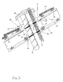
- sheet piece 1 below the external ceiling lining is provided with a raised portion 9 in an area surrounding at least a opening for the passage of channels 3, 4 in the form of tubes or the like in the ceiling or wall. The raised sheet portion is thus preventing ingress of water from an underroof 19, see e.g. Fig.
- the ceiling passage has a sealing situated above a potential flow level for water on the underroof 19.
- the ceiling lining can further comprise roof tiles 21 arranged on underlying laths 22 being arranged in desired distance from the underroof by means of distance laths 23.
- the lower collar 1 and support plate 2 for arrangement in the ceiling are formed with an opening for each of the tubes.
- the passage is illustrated for one or two tubes 3, 4 but this is of course not excluding that the two sheet pieces 1, 2 can have openings for more that the tubes depicted.
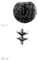
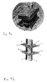
- the respective opening is provided with a flexible gasket 5, 6, 7, 8, see e.g. Fig. 2b and 4b .
- Each gasket is dimensioned to be situated in a sealed manner against an outer circumferential surface at the corresponding tube 3, 4, namely around the total tube circumference.
- gaskets 5, 6 on the lower collar 1 are flexible weatherproof rubber gaskets of appropriate type. Further, it is understood that all gaskets can be fixed to the respective sheet piece in any suitable manner known in the art. Thereby, it is automatically achieved a water-tight and air-tight passage when using smooth tubes. In case of passages using pipe coils, due to the construction having seams in circles, it should be striven for an arrangement in which the pipe coil is located in a manner involving that each gaskets 5, 6, 7, 8 are not situated over one of the seams but in a smooth portion. However, this is not always possible in practise.
- the solution is then to fill at least one possibly open space between gaskets and seams on pipe coils with suitable joint filler. The joint filler can thereby prevent passing of water, for instance, in such transition areas.
- the two sheet pieces 1,2 are each mounted to a frame consisting of bearing strips 10, 11, 12, 13 or load bearing elements 14, 15, respectively, being situated between a pair of adjacent rafters 20 or uprights 24 and arranged in an area at outer edges of the respective sheet piece or between the outer edges and the at least one opening.
- the frame of sheet piece 1 below the external ceiling lining is formed of four bearing strips 10, 11, 12, 13 extending in pairs transversal or longitudinal to the rafters 20.
- the bearing strips can be formed in each corner area in a manner securing a tight abutting surface against the lower collar 1, e.g. by forming each end of the bearing strips 10, 11, 12, 13 like a recessed portion.
- the frame for the sheet piece 2 below the internal roofing and/or the two support pieces 1, 2 below the external and internal wall lining are formed from at least to load bearing elements 14, 15 extending transversal to the rafters 20 or uprights 24.
- the frame can be supplemented with two additional load bearing elements, not illustrated, extending transversal between the load bearing elements 14, 15 as to achieved the best possible sealing in the area between an internal moisture barrier 25 in the ceiling or wall and an external wind barrier 26 in the wall.
- Both the passage in the ceiling and in the wall can be filled with a suitable insulating material 27.
- the internal ceiling or wall lining comprises an inner layer 28 made from a useful material, e.g. plaster boards, when needed being fastened to an extension in the form of laths 29.
- the support plate 2 of the internal roofing and the two support plates 1, 2 of the external and internal wall lining, respectively, have in a favourable manner a width at least corresponding to a normal centre distance between the two adjacent rafters 20 or uprights 24, i.e. 600 mm.
- the width can be adapted such as by cutting the sheet pieces beyond the at least one opening, if the mounting is to occur in an end area of the ceiling or wall, unless the centre distance is as normal.
- the same sheet pieces 1, 2 can be from an appropriate material, e.g. metal.
- the support plate 1 below the external wall lining can of course be made without any raised portion such as on the lower collar 1.
- At least the sheet piece 1 below the external ceiling lining in the area at the frame 10, 11, 12, 13 is provided with a bulb 16 filled with a joint filler and is sealing the mounted sheet piece and frame. This can be performed in any suitable manner and is within the competence of skilled persons and is not to further discussed here.
- the device for mounting a vent pipe guard 17 over ends of the tubes 3, 4 the device is comprising in connection with the sheet piece 1 below the external ceiling lining a securing element 18 arranged in a lower area of the sheet piece transversal to the rafters 20 and is adapted to be situated in an end area of a roof covering, e.g. the roof tiles 21.
- the securing element 18 can be fastened to the distance laths 23 keeping the laths 22 in distance from the underroof 19, see Fig. 1 and 3 .
- the vent pipe guard 17 can be provided with a lower profiling adapted to the surface of the roof tiles 21, see Fig. 2 and 4a .
- a wall hood 30 being a so-called combibox, see Fig. 5 .
- the wall hood comprises a covering 31, preferentially extending inwards below an overlapping panel board.
- the present device is further described for the sealing of a channel passage through a ceiling comprising a lower ceiling 19 of foil, paper, plywood and various other "simplified underroofs" available in the market.
- the device is distinguishing itself inter alia in that the mounting of the lower collar 1 can be performed from the upper side of the roof without any actions from the lower side, whereby it is achieved a sealed ceiling passage through the modem underroofs of today.
- the underroof 19 between the rafters 20 at the lower collar 1 is thus stiffened by arranging a frame along the four edges of the lower collar and thus around the at least one opening.
- the frame mounting occurs by means of fittings, see Fig. 8 , in the form of four so-called support laths 10, 11, 12, 13 being lowered down below a hole 32 in the underroof 19, see Fig. 7 , and the recessed portions on the support laths 10, 11 in between the rafters 20 and underroof on each side and then to be fastened from above into each rafter which are performed occurs at the upper and lower portion of the hole 32.
- the support laths 12, 13 are situated to the right and left hand side of the hole 32 below the underroof 19 and screwed to the transversal support laths 10, 11, see Fig. 8 .
- the frame is provided around and below the hole 32 in the underroof 19, whereby the mounting of the lower collar 1 can be performed.
- it is a bulb 17 around the outer edges of the lower collar 1.
- the bulb 17 is filled with joint filler and is screwed against the frame for the support laths 10, 11, 12, 13, see Fig. 8 .
- the support plate 2 is mounted, see below, the actual tube passage is thereby made ready.
- the support plate 2 for the ceiling passage is to be part of a ceiling presupposing use of a moisture barrier 25, i.e. then facing a heated zone within the building.
- the support plate 2 which in that respect also are applicable to the support plates 1, 2 of the wall passage, usually having both a moisture and wind barrier is always situated at a pair adjacent rafters 20 and is therefore having the same need of structural support in the form of load bearing elements 14, 15, see Fig. 9 , whereby the same sealing is achieved against the internal moisture barrier, see Fig. 11 .
- Support plate configuration as to the passage and sealing between the tubes 3, 4 and the weatherproof rubber gaskets 6, 7 is identical to the lower collar 1, except for the raised portion consequently involving that the support platen therefore is completely flat.
Landscapes
- Engineering & Computer Science (AREA)
- Chemical & Material Sciences (AREA)
- Combustion & Propulsion (AREA)
- Mechanical Engineering (AREA)
- General Engineering & Computer Science (AREA)
- Building Environments (AREA)
Applications Claiming Priority (1)
| Application Number | Priority Date | Filing Date | Title |
|---|---|---|---|
| NO20084512 | 2008-10-27 |
Publications (1)
| Publication Number | Publication Date |
|---|---|
| EP2180268A2 true EP2180268A2 (de) | 2010-04-28 |
Family
ID=41571775
Family Applications (1)
| Application Number | Title | Priority Date | Filing Date |
|---|---|---|---|
| EP20090013516 Withdrawn EP2180268A2 (de) | 2008-10-27 | 2009-10-27 | Vorrichtung zur Durchführung von Kanälen in Dachböden oder Wänden |
Country Status (1)
| Country | Link |
|---|---|
| EP (1) | EP2180268A2 (de) |
-
2009
- 2009-10-27 EP EP20090013516 patent/EP2180268A2/de not_active Withdrawn
Similar Documents
| Publication | Publication Date | Title |
|---|---|---|
| US4625469A (en) | Replacement flat roof insulation cover | |
| US4277926A (en) | Vented insulation system for existing structure | |
| US9709296B1 (en) | Ductwork system | |
| US20110209423A1 (en) | Roof with Ridge Vent Brace | |
| EP0018338B1 (de) | Verfahren zum Bau eines energiesparenden Gebäudes und ein solches Gebäude | |
| JP2008513640A (ja) | 組み立て式屋根用囲い枠組 | |
| EP1715261A1 (de) | Modulares Solarenergiekollektorelement für eine Einhausung und modulares System zur Bildung von Sonnenenergie sammelnden Einhausungen auf Gebäuden | |
| CN205134762U (zh) | 单层屋面防水压型钢板 | |
| EP4073409B1 (de) | Feuerfester belüftungskanal und verfahren zur herstellung und installation solch eines belüftungskanals | |
| US20130247489A1 (en) | Attic conditioning system and method | |
| EP2180268A2 (de) | Vorrichtung zur Durchführung von Kanälen in Dachböden oder Wänden | |
| JP5597111B2 (ja) | 建物の建築方法 | |
| JP2009041266A (ja) | 外断熱用複合パネルおよびこれを用いた目地構造 | |
| CN211690918U (zh) | 一种透气墙 | |
| JP4034084B2 (ja) | 下屋屋根と外壁との間の止水構造 | |
| CN207686052U (zh) | 一种带穿墙管道的防水隔气墙体结构 | |
| JP2715062B2 (ja) | 太陽熱集熱屋根 | |
| CN222907238U (zh) | 一种通风防水的电梯井道顶盖 | |
| JPH09144156A (ja) | 断熱屋根構造及び断熱パネル | |
| CN223855047U (zh) | 管线穿墙防水结构及装配式建筑 | |
| FI130991B1 (fi) | Ulkoseinäelementti ja rakennus | |
| CN217871455U (zh) | 一种压型金属屋面板通风口节点结构 | |
| CN110409977A (zh) | 曲面形百叶防雨通风窗 | |
| JP3607099B2 (ja) | 瓦棟構造及び棟排気システム | |
| JP5215626B2 (ja) | 通気層形成部材、通気構造及び空調システム |
Legal Events
| Date | Code | Title | Description |
|---|---|---|---|
| PUAI | Public reference made under article 153(3) epc to a published international application that has entered the european phase |
Free format text: ORIGINAL CODE: 0009012 |
|
| AK | Designated contracting states |
Kind code of ref document: A2 Designated state(s): AT BE BG CH CY CZ DE DK EE ES FI FR GB GR HR HU IE IS IT LI LT LU LV MC MK MT NL NO PL PT RO SE SI SK SM TR |
|
| AX | Request for extension of the european patent |
Extension state: AL BA RS |
|
| STAA | Information on the status of an ep patent application or granted ep patent |
Free format text: STATUS: THE APPLICATION IS DEEMED TO BE WITHDRAWN |
|
| 18D | Application deemed to be withdrawn |
Effective date: 20120503 |