EP2178708B1 - Pair of pneumatic tyres for two -wheeled vehicles - Google Patents
Pair of pneumatic tyres for two -wheeled vehicles Download PDFInfo
- Publication number
- EP2178708B1 EP2178708B1 EP07766627.9A EP07766627A EP2178708B1 EP 2178708 B1 EP2178708 B1 EP 2178708B1 EP 07766627 A EP07766627 A EP 07766627A EP 2178708 B1 EP2178708 B1 EP 2178708B1
- Authority
- EP
- European Patent Office
- Prior art keywords
- tyre
- pair
- tyres
- cords
- angle
- Prior art date
- Legal status (The legal status is an assumption and is not a legal conclusion. Google has not performed a legal analysis and makes no representation as to the accuracy of the status listed.)
- Not-in-force
Links
Images


Classifications
-
- B—PERFORMING OPERATIONS; TRANSPORTING
- B60—VEHICLES IN GENERAL
- B60C—VEHICLE TYRES; TYRE INFLATION; TYRE CHANGING; CONNECTING VALVES TO INFLATABLE ELASTIC BODIES IN GENERAL; DEVICES OR ARRANGEMENTS RELATED TO TYRES
- B60C19/00—Tyre parts or constructions not otherwise provided for
- B60C19/001—Tyres requiring an asymmetric or a special mounting
-
- B—PERFORMING OPERATIONS; TRANSPORTING
- B60—VEHICLES IN GENERAL
- B60C—VEHICLE TYRES; TYRE INFLATION; TYRE CHANGING; CONNECTING VALVES TO INFLATABLE ELASTIC BODIES IN GENERAL; DEVICES OR ARRANGEMENTS RELATED TO TYRES
- B60C15/00—Tyre beads, e.g. ply turn-up or overlap
- B60C15/0009—Tyre beads, e.g. ply turn-up or overlap features of the carcass terminal portion
- B60C15/0018—Tyre beads, e.g. ply turn-up or overlap features of the carcass terminal portion not folded around the bead core, e.g. floating or down ply
-
- B—PERFORMING OPERATIONS; TRANSPORTING
- B60—VEHICLES IN GENERAL
- B60C—VEHICLE TYRES; TYRE INFLATION; TYRE CHANGING; CONNECTING VALVES TO INFLATABLE ELASTIC BODIES IN GENERAL; DEVICES OR ARRANGEMENTS RELATED TO TYRES
- B60C9/00—Reinforcements or ply arrangement of pneumatic tyres
- B60C9/02—Carcasses
- B60C9/0207—Carcasses comprising an interrupted ply, i.e. where the carcass ply does not continuously extend from bead to bead but is interrupted, e.g. at the belt area, into two or more portions of the same ply
-
- B—PERFORMING OPERATIONS; TRANSPORTING
- B60—VEHICLES IN GENERAL
- B60C—VEHICLE TYRES; TYRE INFLATION; TYRE CHANGING; CONNECTING VALVES TO INFLATABLE ELASTIC BODIES IN GENERAL; DEVICES OR ARRANGEMENTS RELATED TO TYRES
- B60C9/00—Reinforcements or ply arrangement of pneumatic tyres
- B60C9/02—Carcasses
- B60C9/04—Carcasses the reinforcing cords of each carcass ply arranged in a substantially parallel relationship
- B60C9/08—Carcasses the reinforcing cords of each carcass ply arranged in a substantially parallel relationship the cords extend transversely from bead to bead, i.e. radial ply
- B60C9/09—Carcasses the reinforcing cords of each carcass ply arranged in a substantially parallel relationship the cords extend transversely from bead to bead, i.e. radial ply combined with other carcass plies having cords extending diagonally from bead to bead, i.e. combined radial ply and bias angle ply
-
- B—PERFORMING OPERATIONS; TRANSPORTING
- B60—VEHICLES IN GENERAL
- B60C—VEHICLE TYRES; TYRE INFLATION; TYRE CHANGING; CONNECTING VALVES TO INFLATABLE ELASTIC BODIES IN GENERAL; DEVICES OR ARRANGEMENTS RELATED TO TYRES
- B60C9/00—Reinforcements or ply arrangement of pneumatic tyres
- B60C9/18—Structure or arrangement of belts or breakers, crown-reinforcing or cushioning layers
- B60C9/20—Structure or arrangement of belts or breakers, crown-reinforcing or cushioning layers built-up from rubberised plies each having all cords arranged substantially parallel
- B60C9/22—Structure or arrangement of belts or breakers, crown-reinforcing or cushioning layers built-up from rubberised plies each having all cords arranged substantially parallel the plies being arranged with all cords disposed along the circumference of the tyre
- B60C9/2204—Structure or arrangement of belts or breakers, crown-reinforcing or cushioning layers built-up from rubberised plies each having all cords arranged substantially parallel the plies being arranged with all cords disposed along the circumference of the tyre obtained by circumferentially narrow strip winding
-
- B—PERFORMING OPERATIONS; TRANSPORTING
- B60—VEHICLES IN GENERAL
- B60C—VEHICLE TYRES; TYRE INFLATION; TYRE CHANGING; CONNECTING VALVES TO INFLATABLE ELASTIC BODIES IN GENERAL; DEVICES OR ARRANGEMENTS RELATED TO TYRES
- B60C2200/00—Tyres specially adapted for particular applications
- B60C2200/10—Tyres specially adapted for particular applications for motorcycles, scooters or the like
-
- Y—GENERAL TAGGING OF NEW TECHNOLOGICAL DEVELOPMENTS; GENERAL TAGGING OF CROSS-SECTIONAL TECHNOLOGIES SPANNING OVER SEVERAL SECTIONS OF THE IPC; TECHNICAL SUBJECTS COVERED BY FORMER USPC CROSS-REFERENCE ART COLLECTIONS [XRACs] AND DIGESTS
- Y10—TECHNICAL SUBJECTS COVERED BY FORMER USPC
- Y10T—TECHNICAL SUBJECTS COVERED BY FORMER US CLASSIFICATION
- Y10T152/00—Resilient tires and wheels
- Y10T152/10—Tires, resilient
- Y10T152/10495—Pneumatic tire or inner tube
- Y10T152/10765—Characterized by belt or breaker structure
Definitions
- the present invention relates to a pair of pneumatic tyres particularly adapted to equip two-wheeled vehicles.
- a tyre generally comprises: a carcass structure having at least one carcass ply the ends of which are in engagement with respective circumferential annular reinforcing structures integrating annular elements usually identified as "bead cores"; a belt structure applied at a radially external position to the carcass structure; a pair of sidewalls applied at an axially external position to side surfaces of the carcass structure, each extended radially away from one of the annular anchoring structures towards said belt structure; a tread band usually consisting of a strip of elastomeric material of suitable thickness, which is applied onto the belt structure at a radially external position. Formed in the tread band, following a moulding operation carried out concurrently with vulcanisation of the tyre, are longitudinal and/or transverse grooves such disposed as to define a desired "tread pattern".
- the carcass structure can be coated, on its inner walls, with an air-proof layer generally termed "liner".
- liner is essentially made up of a layer of an airtight elastomeric material that in tubeless tyres is adapted to ensure hermetic sealing of the tyre itself, once inflated.
- tyres for two-wheeled vehicles are distinguishable due to their marked transverse curvature.
- a force in the direction on which the camber angle acts is generated, which force opposes the centrifugal force.
- the force thus generated is a function of the curvature and deformations to which the tyre is subjected under these conditions. These deformations are to be avoided as they involve localised temperature increases, greater energy dispersion and blend slippage.
- the sidewalls of said tyre must be strengthened with additional reinforcing elements.
- a reinforcement for tyres which is assembled on a collapsible drum and subsequently applied to the tyre carcass.
- the reinforcement is formed of axially adjacent layers upon interposition of an elastomeric filling element.
- Each layer is defined by a plurality of coils disposed radially close to each other and extending in a sinuous course with a predetermined pitch and width.
- the coils of two distinct layers are circumferentially offset with respect to each other by about half a pitch.
- annular stiffening inserts placed at the sidewalls of radial tyres to increase stiffness thereof has been proposed by the Applicant, said annular inserts being obtained through circumferential winding of at least one continuous filament-like element on several continuous turns so as to form a series of coils disposed radially close to each other and concentric with the geometrie rotation axis of the tyre.
- a motorcycle tyre is disclosed provided with a reinforced carcass comprising cords disposed over the carcass at an angle of 20° to 50° to the circumferential direction. Similar reinforced carcass are also described in documents GB2102354 , EP0483710 and EP0507184 .
- Both said types of torque involve a tyre distortion and consequently modify the shape of the tyre footprint above all on a bend, generate localised rises in temperature and increase consumptions.
- the Applicant has faced up to the problem of increasing the tyre resistance to distortion due to application both of twisting moments both on braking and of twisting moments on acceleration.
- the Applicant has faced the problem of reducing the delay in the tyre response following deformations induced on braking and on acceleration.
- the Applicant has also faced up to the problem of increasing stiffness of the sidewalls in radial tyres, while maintaining the advantages typical of a tyre with a radial structure in terms of lightness in weight, ride comfort and structural resistance to high speeds.
- the Applicant has found that said problems can be solved by producing a pair of tyres designed to be mounted on the rear and front wheels of a two-wheeled vehicle, in which each tyre of the pair is provided with a pair of reinforcing structures disposed at the tyre sidewalls and comprising a plurality of inclined cords.
- the present invention relates to a pair of tyres comprising a front tyre and a rear tyre to be mounted on a front and rear wheels respectively of a two-wheeled vehicle, wherein each of said front and rear tyres comprises:
- the angle ( ⁇ ) is constant or variable in a monotonic manner over the whole length of the cord.
- the cords of the reinforcing side structure are such disposed as to be subjectted, during rolling of the tyre, to a force hindering deformation of the tyre itself, as better illustrated in the following.
- each reinforcing side structure is a substantially annular structure.
- the reinforcing structure has a height greater than or equal to 20% of the height of the sidewall.
- the present invention relates to a tyre for two-wheeled vehicles comprising:
- the angle ( ⁇ ) is variable in a monotonic manner over the whole length of said cord.
- said angle ( ⁇ ) is larger than or equal to 20°.
- said angle ( ⁇ ) is included within the range of 20° to 89°, inclusive of the extremes, for a front tyre.
- the cords are made of metal.
- the cords comprise high-module textile fibres.
- fibres with a modulus of elasticity of at least approximately 25000 N/mm2.
- a tyre for two-wheeled vehicles has been generally identified with 100 or 200; it comprises a carcass structure including at least one carcass ply 2 preferably having a first and a second carcass half-plies 3, 4, said carcass ply 2 being shaped in a substantially toroidal configuration and being in engagement, by its opposite circumferential edges, with at least one annular reinforcing structure 9, so as to form a structure usually identified as "bead".
- the carcass ply 2 is preferably formed of two carcass half-plies 3, 4. This carcass ply 2 is built following the method shown in document WO 00/38906 .
- carcass half-ply it is intended a structure having a substantially toroidal extension which is formed of a plurality of strip-like elements placed at a mutual distance which is substantially the same as the transverse size of the strip-like element itself.
- the annular reinforcing structure 9 has at least one annular insert made up of a preferably metallic thread element at least partly coated with an elastomeric material and formed into substantially concentric coils, each coil being alternatively defined by a length of a continuous spiral or by concentric rings formed of respective filament-like elements.
- annular inserts 9a and 9b are provided as well as a filler 22 of elastomeric material placed at an axially external position to the first annular insert 9a.
- the second annular insert 9b still as shown in Fig. 1 , is disposed at an axially external position to the second half-ply 4.
- a further filler 23 is provided which completes manufacture of the annular reinforcing structure 9.
- the carcass ply 2 is of the so-called traditional type.
- This carcass ply 2 has its opposite side edges associated with particular annular reinforcing structures identified as bead cores.
- association between the carcass ply and bead cores takes place by turning up the opposite side edges of the carcass ply around the bead cores themselves, so as to form the so-called carcass end flaps.
- the carcass ply preferably comprises textile cords selected from those usually adopted in manufacturing tyre carcasses, made of nylon, rayon, PET, PEN for example, with an elementary thread of a diameter included between 0.35 mm and 1.5 mm.
- a belt structure 5 Circumferentially applied to the carcass ply, at a radially external position, is a belt structure 5 and circumferentially superposed thereon is a tread band 6 in which, following a moulding operation carried out concurrently with the tyre vulcanisation, longitudinal and transverse grooves such arranged as to give rise to a desired "tread pattern" are formed.
- Tyre 100, 200 also comprises a pair of sidewalls 7 laterally applied to said carcass structure, on opposite sides thereof.
- Said tyre 100 or 200 has a right section marked by a high transverse curvature.
- tyre 1 has a section height H measured in the equatorial plane between the centre of the tread band and the fitting diameter identified by the reference line r passing through the tyre beads.
- Tyre 100 or 200 further has a width C defined by the distance between the laterally opposite ends E of the tread band and a curvature defined by the particular value of the ratio between the distance f of the tread centre from the line passing through the ends E of the tread itself, measured in the equatorial tyre plane, and width C.
- tyres having a curvature ratio f/C ⁇ 0.2 and preferably f/C ⁇ 0.28.
- This curvature ratio is, at all events, ⁇ 0.8 and preferably f/C ⁇ 0.5.
- the invention preferably applies to tyres with sidewalls that are not particularly low ( Fig. 1 ).
- tyres with sidewalls that are not particularly low it is intended tyres in which the height-sidewall ratio (H-f)/H is greater than 0.4 (see Fig. 1 ).
- the carcass structure may be possibly coated on its inner walls with an air-proof layer 8 or a so-called "liner", essentially made up of a layer of an airtight elastomeric material adapted to ensure hermetic sealing of the tyre itself, once inflated.
- the belt structure 5 comprises a layer having a plurality of circumferential coils disposed in axial side by side relationship, and consisting of a rubberised cord 5a or a strip-like element comprising some rubberised cords 5a (preferably 2 to 5), spirally wound up at a substantially zero angle relative to the equatorial plane X-X of the tyre.
- the cords 5a of the belt structure 5 are textile or metallic cords.
- said cords 5a are made of high-carbon (HT) steel wires, i.e. steel wires containing more than 0.9% of carbon.
- HT high-carbon
- said steel cords are high-elongation cords of the type described in patent EP461646 in the name of the same Applicant for achieving a soft behaviour of the tyre at low speed and a stiff behaviour at high speed.
- these cords 5a are steel cords of the high-elongation type, generally known as "HE", wound in the same direction (Lang's lay cords), in other words steel cords having an ultimate elongation included between 4% and 8%.
- HE high-elongation type
- these cords consist of a given number of strands, 1 to 5, and preferably 3 to 4.
- Each strand is made up of a given number of basic threads, 2 to 10 and preferably 4 to 7.
- Each basic thread has a diameter larger than 0.10 mm, preferably included between 0.12 and 0.25 mm.
- the basic threads in the strands and the strands in the cord are helically wound together in the same direction, with the same or different winding pitches for the threads and the strands.
- These cords 5a as described in patent EP461646 , are characterised by a particular load-elongation diagram showing a curvilinear portion connecting two stretches that are substantially straight but of different slope.
- Cords 5a in the deflated tyre are provided in a (load-elongation) condition corresponding in said diagram to a particular point, termed "G", which is in the curvilinear portion, which portion has an elongation value typically included between 1.5% and 3%.
- cords 5a In use, due to tension generated by tyre inflation and high speed, cords 5a shall, on the contrary, work in their region at a high modulus or a low elongation.
- textile cords can be employed, and these can consist of synthetic fibres, nylon, rayon, PEN, PET for example, preferably high-modulus synthetic fibres, in particular aramidic fibres (Kevlar® fibres, for example).
- hybrid fibres can be employed which comprise at least one low-modulus thread, i.e. a modulus not exceeding about 15000 N/mm2 (nylon or rayon for example), interlaced with at least one high-modulus thread (Kevlar®, for example), i.e. a modulus at least as high as 25000 N/mm2.
- the belt structure 5 can consist of at least two radially superposed layers, each made up of elastomeric material reinforced with cords disposed parallel to each other.
- the layers are disposed in such a manner that the cords of the first belt layer are oriented obliquely to the equatorial plane of the tyre, while the cords of the second layer have an oblique orientation too, but they symmetrically cross the cords of the first layer (forming a so-called "crossed belt”).
- tyre 100 or 200 can also comprise a layer 10 of elastomeric material placed between said carcass structure and said belt structure 5 formed of said circumferential coils, said layer 10 preferably extending on a surface substantially corresponding to the extension surface of said belt structure 5.
- said layer 10 extends on a smaller surface than the extension surface of the belt structure 5, only on opposite side surfaces thereof, for example.
- an additional layer of elastomeric material (not shown in Fig. 1 ) is placed between said belt structure 5 formed of said circumferential coils, and said tread band 6, said layer preferably extending over a surface substantially corresponding to the extension surface of said belt structure 5.
- said layer only extends along at least one portion of the belt structure 5 extension, on opposite side portions thereof for example.
- At least one of said layer 10 and additional layer comprises short aramidic fibres, Kevlar® fibres for example, dispersed in said elastomeric material.
- the tyre in accordance with the invention comprises a pair of reinforcing side structures 12 laterally applied at the sidewalls.
- Each reinforcing side structure 12 comprises a plurality of cords 13 at least partly embedded in at least one layer of elastomeric material.
- the reinforcing side structure 12 circumferentially extends preferably in a continuous annular manner around the rotation axis of the tyre itself.
- each reinforcing side structure 12 extends from a radially innermost position relative to the radially outermost end of the circumferential annular structure 9b.
- the reinforcing side structure 12 extends from the radially innermost end of the tyre sidewall over at least 20% of the sidewall height.
- the reinforcing structure 12 extends over the whole height of sidewall 7 until reaching said belt structure 5.
- the reinforcing structure 12 comes into contact with the belt structure 5 and the latter overlaps the reinforcing side structure 12 over a given stretch thereof.
- each reinforcing structure 12 comprises a plurality of cords 13 disposed inclined to a circumferential direction of the tyre.
- a angle ( ⁇ ) is identified between the tangent of the cord direction at that point and the tangent to a circumferential direction of the tyre passing through that point and oriented in the rolling direction.
- the angle ( ⁇ ) is greater than or equal to 20°. Most preferably, the angle ( ⁇ ) is greater than 30°.
- the angle ( ⁇ ) is included in the range of 20° to 89°, inclusive of the extremes, for a front tyre and is included in the range of 91° to 160°, inclusive of the extremes, for a rear tyre.
- the angle ( ⁇ ) is constant over the whole length of the cord.
- the angle ( ⁇ ) is varying in a monotonic manner along the whole length of said cord 13. At all events, this angle ( ⁇ ) is always larger than 20° or included in the above mentioned preferred ranges, over the whole length of the cord.
- cords 13 of the annular reinforcing structure 12 are made of steel wires.
- said cords 13 are made of low-carbon steel wires, i.e. steel wires containing less than 0.7% of carbon.
- cords 13 of the textile type can be used, which can be made of synthetic fibre such as nylon, rayon, PEN, PET.
- high-modulus fibres are concerned, in particular aramidic fibres (Kevlar® fibres, for example).
- cords 13 of the hybrid type can be employed, which comprise at least one low-modulus thread, i.e. not beyond about 15000 N/mm2 (nylon or rayon, for example), interlaced with at least one high-modulus thread, i.e. not less than 25000 N/mm2 (Kevlar®, for example).
- density of cords 13 defining the reinforcing structures 12 is greater than 40 cords/dm, most preferably greater than 70 cords/dm.
- density of cords 13 can be conveniently maintained to a smaller value than 160 cords/dm, more preferably smaller than 110 cords/dm.
- Density of cords 13 defining the reinforcing structures 12 can be measured with reference to any circumferential direction on the tyre sidewall included within the reinforcing structure itself.
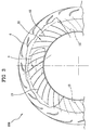
- the cords 13 of the inventive tyre can further have a substantially rectilinear course, as shown in Fig. 2 or alternatively, as shown in Fig. 3 , a substantially curvilinear course.
- the reinforcing side structure 12 is formed of thread elements comprising a cord, such as a rubberised thread or a strip-like element.
- each reinforcing side structure 12 is made up of rubberised strip-like elements preferably disposed in side by side relationship with each other along the circumferential extension of said tyre. In this way, at the end of a tyre rotation around its rotation axis, a closed annular structure is created.
- the strip-like elements have a width included between 5 mm and 20 mm, a thickness included between 0.5 mm and 2 mm, and contain a number of cords in the range of 4 to 40, with a density preferably included between 60 and 160 cords per decimetre.
- the inventive tyre is particularly suitable for use on a two-wheeled vehicle both as front tyre 100 and as rear tyre 200, as shown in Fig. 4 .
- Tyres 100 and 200 have a rotation direction of their own that must be coincident with the rotation due to the forward running direction of the vehicle and is denoted by arrows F in Fig. 4 .
- an angle ( ⁇ ) different from zero is identified, which is included between the tangent of the cord direction at that point and the tangent to a circumferential direction of the tyre passing through said point and oriented in said rotation direction of the tyre.
- the angle ( ⁇ ) being formed is larger than 90° while in the front tyre 100 the angle ( ⁇ ) is smaller than 90°.
- the angle ( ⁇ ) is included in the range between 20° and 89°, inclusive of the extremes, for a front tyre, while it is included in the range of 91° to 160°, inclusive of the extremes, for a rear tyre.
- a pair like that depicted above acts particularly well for reducing the tyre deformations or distortions on application of a torque.
- this condition mainly occurs on the rear tyre 200 when the vehicle is subjected to acceleration, and mainly on the front tyre 100 when the vehicle is subjected to braking.
- tyre 200 is subjected to a twisting moment in the same direction as that of the tyre rotation.
- the rear-tyre cords 13 are subjected to a tension.
- Inclination of the cords 13 disposed at an angle ( ⁇ ) larger than 90° in the rear tyre 200 increases the tensioning velocity of cords 13, reducing tyre deformation and increasing the tyre response speed. In fact, with such an orientation, the time employed by a cord for stretching is reduced.
- the front tyre 100 On braking, on the contrary, the front tyre 100 is subjected to a twisting moment in the direction opposite to the rotation direction of the tyre and in this case too the cords 13 of the front tyre 100 will be subjected to tensioning.
- the inclination of cords 13 at an angle ( ⁇ ) smaller than 90° in the front tyre 100 increases the tensioning velocity of cords 13, reducing deformation and increasing the tyre response speed.
- FIG. 5 is a diagram showing the variation in the percent difference of some stiffness parameters as a function of the load acting on the tyre (expressed in kg), between a rear tyre in accordance with the invention and a reference tyre of the traditional type showing the same outer geometry (curvature, sidewall height and type of tread pattern).
- the reference tyre is a rear tyre size 205/60 R420.
- curve A in Fig. 5 measures the percent variation in the cornering stiffness on varying of the load imposed on the tyre.
- a 100 kg load can be a good representation of the tyre in the initial bend step, while in the middle of a bend a load of 200 kg can be appropriate.
- the relaxation length is an index of the quick response of the tyre.
- the relaxation length is inversely proportional to the response quickness of the tyre. In this case too, it is possible to immediately observe that under any situation, with the inventive tyre, the relaxation length is at least 8% less than that expressed by the reference tyre. This denotes a much readier tyre under any bending condition.
- Fig. 6 is a diagram showing the variation in the percent difference of some stiffness parameters to a given vertical load imposed to the tyre, between a rear tyre of the invention and a traditional reference tyre.
- the reference tyre is a rear tyre size 205/60 R420.
- histogram E denotes the vertical-deflection difference between the tyre of the invention and the reference tyre if subjected to a 300 kg vertical load. It is possible to see that the vertical deflection of the inventive tyre is 10.2% less.
- Histogram D shows the difference in the longitudinal stiffness between the inventive tyre and the reference tyre if subjected to a 300 kg vertical load and a longitudinal force.
- longitudinal force it is intended a force applied in the tyre centre and directed in the forward-movement direction of the tyre.
- the longitudinal stiffness is measured as the ratio between the longitudinal force applied thereto and the displacement induced in the tyre, in the forward-movement direction. Therefore, the applied longitudinal force being the same, a smaller displacement corresponds to a greater longitudinal stiffness. Since this force, depending on its application point, produces a torque transferred from the tyre bead to the ground, the longitudinal stiffness measures the tyre capability of resisting a torque applied thereto. Therefore, as visible in Fig. 6 , the tyre of the invention increases its longitudinal stiffness by almost 50% relative to the reference tyre. In other words, it resists in a much more efficient manner to application of a torque.
- histogram C denotes the difference in the lateral stiffness between the inventive tyre and the reference tyre if they are subjected to a 300 kg vertical load and a lateral force.
- lateral force it is intended a force applied into the tyre centre and directed orthogonal to the forward-movement direction of the tyre.
- the lateral stiffness is measured as the ratio between the lateral force applied thereto and the displacement induced in the tyre, in a direction orthogonal to the forward-movement direction. Therefore, the applied lateral force being the same, a smaller displacement corresponds to a greater lateral stiffness.
- This value is an index of the tyre deformability in a direction orthogonal to the forward-movement direction of the tyre.
- the tyre of the invention therefore, as represented in histogram C in Fig. 6 , increases its lateral stiffness by almost 20% relative to the reference tyre and therefore deformations are much more reduced if it is subjected to laterally-directed stresses.
Landscapes
- Engineering & Computer Science (AREA)
- Mechanical Engineering (AREA)
- Tires In General (AREA)
Applications Claiming Priority (1)
| Application Number | Priority Date | Filing Date | Title |
|---|---|---|---|
| PCT/IB2007/001993 WO2009010813A1 (en) | 2007-07-16 | 2007-07-16 | Pair of pneumatic tyres for two -wheeled vehicles |
Publications (2)
| Publication Number | Publication Date |
|---|---|
| EP2178708A1 EP2178708A1 (en) | 2010-04-28 |
| EP2178708B1 true EP2178708B1 (en) | 2017-11-08 |
Family
ID=39118817
Family Applications (1)
| Application Number | Title | Priority Date | Filing Date |
|---|---|---|---|
| EP07766627.9A Not-in-force EP2178708B1 (en) | 2007-07-16 | 2007-07-16 | Pair of pneumatic tyres for two -wheeled vehicles |
Country Status (5)
| Country | Link |
|---|---|
| US (1) | US20100180999A1 (zh) |
| EP (1) | EP2178708B1 (zh) |
| CN (1) | CN101730629B (zh) |
| BR (1) | BRPI0721872A2 (zh) |
| WO (1) | WO2009010813A1 (zh) |
Families Citing this family (4)
| Publication number | Priority date | Publication date | Assignee | Title |
|---|---|---|---|---|
| US10562353B2 (en) | 2012-01-16 | 2020-02-18 | Compagnie Generale Des Etablissements Michelin | Tire construction with flattened summit and circumferential reinforcement |
| JP2013177065A (ja) * | 2012-02-28 | 2013-09-09 | Sumitomo Rubber Ind Ltd | 空気入りタイヤ |
| CN108602386B (zh) * | 2015-10-30 | 2021-10-01 | 倍耐力轮胎股份公司 | 用于自行车车轮的轮胎 |
| WO2019115917A1 (fr) * | 2017-12-11 | 2019-06-20 | Compagnie Generale Des Etablissements Michelin | Pneumatique pour vehicule avec structure de rigidification dans la cavite torique interieure |
Family Cites Families (23)
| Publication number | Priority date | Publication date | Assignee | Title |
|---|---|---|---|---|
| GB890502A (en) * | 1957-07-10 | 1962-02-28 | Dunlop Rubber Co | Improvements in or relating to pneumatic tyre covers |
| JPS5820503A (ja) * | 1981-07-29 | 1983-02-07 | Bridgestone Corp | モ−タ−サイクル用空気入りラジアルタイヤ |
| US4573511A (en) * | 1983-11-08 | 1986-03-04 | The Yokohama Rubber Co., Ltd. | Pneumatic tire |
| JPS6288601A (ja) * | 1985-10-14 | 1987-04-23 | Sumitomo Rubber Ind Ltd | 自動二輪車用タイヤ |
| IT1248851B (it) * | 1990-06-14 | 1995-01-30 | Pirelli | Procedimento per la fabbricazione di pneumatici per veicoli a due ruote e pneumatici cosi' prodotti |
| IT1243872B (it) * | 1990-10-29 | 1994-06-28 | Pirelli Transmissioni Ind Spa | Pneumatico radiale con elemento di rinforzo dei fianchi. |
| US5217549A (en) * | 1991-04-04 | 1993-06-08 | Bridgestone/Firestone, Inc. | Pneumatic safety tire |
| JP2799322B2 (ja) * | 1993-06-07 | 1998-09-17 | 住友ゴム工業株式会社 | 自動二輪車用空気入りタイヤ |
| US5708655A (en) * | 1996-06-14 | 1998-01-13 | Telefonaktiebolaget L M Ericsson Publ | Method and apparatus for addressing a wireless communication station with a dynamically-assigned address |
| JP2001121928A (ja) * | 1999-10-25 | 2001-05-08 | Bridgestone Corp | 二輪自動車用タイヤ |
| US6845094B1 (en) * | 1999-12-16 | 2005-01-18 | Ut Starcom, Inc. | Network address translation based internet protocol mobility |
| WO2002009956A1 (fr) * | 2000-07-31 | 2002-02-07 | Societe De Technologie Michelin | Pneumatique pour vehicule deux roues comportant un moyen anti-vibration |
| US6856624B2 (en) * | 2001-02-21 | 2005-02-15 | Alcatel | Temporary unique private address |
| US6926054B2 (en) * | 2001-07-20 | 2005-08-09 | Michelin Recherche Et Technique S.A. | Anchoring of a tire carcass |
| US7192235B2 (en) * | 2001-11-01 | 2007-03-20 | Palm, Inc. | Temporary messaging address system and method |
| US6721297B2 (en) * | 2001-11-19 | 2004-04-13 | Motorola, Inc. | Method and apparatus for providing IP mobility for mobile networks |
| ES2259012T3 (es) * | 2001-11-22 | 2006-09-16 | Pirelli Tyre S.P.A. | Neumatico para vehiculo con los laterales reforzados. |
| US7269173B2 (en) * | 2002-06-26 | 2007-09-11 | Intel Corporation | Roaming in a communications network |
| JP3924502B2 (ja) * | 2002-07-04 | 2007-06-06 | 富士通株式会社 | モバイル通信方法およびモバイル通信システム |
| US6956846B2 (en) * | 2002-08-16 | 2005-10-18 | Utstarcom Incorporated | System and method for foreign agent control node redundancy in a mobile internet protocol network |
| AU2003219347A1 (en) * | 2003-03-26 | 2004-10-18 | Pirelli Pneumatici S.P.A. | Pneumatic tyre for two wheeled vehicles |
| US20050025164A1 (en) * | 2003-07-16 | 2005-02-03 | Telefonaktiebolaget L M Ericsson (Publ) | Seamless hand-off of mobile node to a wireless local area network (WLAN) |
| US7793695B2 (en) * | 2005-03-16 | 2010-09-14 | Bridgestone Corporation | Pneumatic radial tire for motorcycle |
-
2007
- 2007-07-16 CN CN200780053677XA patent/CN101730629B/zh not_active Expired - Fee Related
- 2007-07-16 WO PCT/IB2007/001993 patent/WO2009010813A1/en active Application Filing
- 2007-07-16 US US12/452,682 patent/US20100180999A1/en not_active Abandoned
- 2007-07-16 BR BRPI0721872-9A patent/BRPI0721872A2/pt not_active Application Discontinuation
- 2007-07-16 EP EP07766627.9A patent/EP2178708B1/en not_active Not-in-force
Non-Patent Citations (1)
| Title |
|---|
| None * |
Also Published As
| Publication number | Publication date |
|---|---|
| CN101730629A (zh) | 2010-06-09 |
| US20100180999A1 (en) | 2010-07-22 |
| WO2009010813A1 (en) | 2009-01-22 |
| EP2178708A1 (en) | 2010-04-28 |
| CN101730629B (zh) | 2011-08-10 |
| BRPI0721872A2 (pt) | 2013-03-26 |
Similar Documents
| Publication | Publication Date | Title |
|---|---|---|
| US5975175A (en) | Pair of high-tranverse-curvature tires for two-wheeled vehicles having different belt structures and method of controlling the behavior of such vehicles on a bend | |
| US8479792B2 (en) | Motorcycle tire and method for manufacturing the same | |
| US9902205B2 (en) | Vehicle tire comprising a layer of circumferential reinforcing elements | |
| KR101970365B1 (ko) | 공기압 타이어용 아코디언 구조의 나선형 오버레이 | |
| CN100420582C (zh) | 双轮机车用充气轮胎 | |
| EP0950546B1 (en) | Tyres with high tranverse curvature coefficient, in particular for a two-wheeled vehicle | |
| EP2178708B1 (en) | Pair of pneumatic tyres for two -wheeled vehicles | |
| US6397911B1 (en) | High transverse-curvature motor-bike tire | |
| WO2009144752A1 (en) | Motorcycle tire | |
| EP3898276B1 (en) | Tyre for vehicle wheels | |
| JPH03135801A (ja) | ラジアルタイヤ | |
| US6244315B1 (en) | Tyre with high transverse curvature coefficient in particular for a two-wheeled vehicle | |
| EP2380755B1 (en) | Overlay ply covering the belt ply for a pneumatic tire | |
| CN101668647B (zh) | 在侧壁中包括加强件的用于车辆的轮胎 | |
| EP2032374B1 (en) | Tyre for vehicle wheels | |
| JP5013522B2 (ja) | 空気入りラジアルタイヤ | |
| JPH11245616A (ja) | 2輪車用の横断曲率の大きいタイヤ及びその製造方法 | |
| US20090120549A1 (en) | Tires for Two-Wheeled Vehicles | |
| KR20050109605A (ko) | 2륜차용 공기 타이어 | |
| JP2009137557A (ja) | ラジアルタイヤ |
Legal Events
| Date | Code | Title | Description |
|---|---|---|---|
| PUAI | Public reference made under article 153(3) epc to a published international application that has entered the european phase |
Free format text: ORIGINAL CODE: 0009012 |
|
| 17P | Request for examination filed |
Effective date: 20100125 |
|
| AK | Designated contracting states |
Kind code of ref document: A1 Designated state(s): AT BE BG CH CY CZ DE DK EE ES FI FR GB GR HU IE IS IT LI LT LU LV MC MT NL PL PT RO SE SI SK TR |
|
| AX | Request for extension of the european patent |
Extension state: AL BA HR MK RS |
|
| DAX | Request for extension of the european patent (deleted) | ||
| RAP1 | Party data changed (applicant data changed or rights of an application transferred) |
Owner name: PIRELLI TYRE S.P.A. |
|
| 17Q | First examination report despatched |
Effective date: 20161124 |
|
| GRAP | Despatch of communication of intention to grant a patent |
Free format text: ORIGINAL CODE: EPIDOSNIGR1 |
|
| RIC1 | Information provided on ipc code assigned before grant |
Ipc: B60C 9/09 20060101AFI20170731BHEP Ipc: B60C 9/22 20060101ALI20170731BHEP Ipc: B60C 9/02 20060101ALI20170731BHEP Ipc: B60C 19/00 20060101ALI20170731BHEP Ipc: B60C 15/00 20060101ALI20170731BHEP |
|
| INTG | Intention to grant announced |
Effective date: 20170822 |
|
| GRAS | Grant fee paid |
Free format text: ORIGINAL CODE: EPIDOSNIGR3 |
|
| GRAA | (expected) grant |
Free format text: ORIGINAL CODE: 0009210 |
|
| AK | Designated contracting states |
Kind code of ref document: B1 Designated state(s): AT BE BG CH CY CZ DE DK EE ES FI FR GB GR HU IE IS IT LI LT LU LV MC MT NL PL PT RO SE SI SK TR |
|
| REG | Reference to a national code |
Ref country code: GB Ref legal event code: FG4D |
|
| REG | Reference to a national code |
Ref country code: CH Ref legal event code: EP Ref country code: AT Ref legal event code: REF Ref document number: 943775 Country of ref document: AT Kind code of ref document: T Effective date: 20171115 |
|
| REG | Reference to a national code |
Ref country code: IE Ref legal event code: FG4D |
|
| REG | Reference to a national code |
Ref country code: DE Ref legal event code: R096 Ref document number: 602007052971 Country of ref document: DE |
|
| REG | Reference to a national code |
Ref country code: NL Ref legal event code: MP Effective date: 20171108 |
|
| REG | Reference to a national code |
Ref country code: LT Ref legal event code: MG4D |
|
| REG | Reference to a national code |
Ref country code: AT Ref legal event code: MK05 Ref document number: 943775 Country of ref document: AT Kind code of ref document: T Effective date: 20171108 |
|
| PG25 | Lapsed in a contracting state [announced via postgrant information from national office to epo] |
Ref country code: SE Free format text: LAPSE BECAUSE OF FAILURE TO SUBMIT A TRANSLATION OF THE DESCRIPTION OR TO PAY THE FEE WITHIN THE PRESCRIBED TIME-LIMIT Effective date: 20171108 Ref country code: NL Free format text: LAPSE BECAUSE OF FAILURE TO SUBMIT A TRANSLATION OF THE DESCRIPTION OR TO PAY THE FEE WITHIN THE PRESCRIBED TIME-LIMIT Effective date: 20171108 Ref country code: LT Free format text: LAPSE BECAUSE OF FAILURE TO SUBMIT A TRANSLATION OF THE DESCRIPTION OR TO PAY THE FEE WITHIN THE PRESCRIBED TIME-LIMIT Effective date: 20171108 Ref country code: ES Free format text: LAPSE BECAUSE OF FAILURE TO SUBMIT A TRANSLATION OF THE DESCRIPTION OR TO PAY THE FEE WITHIN THE PRESCRIBED TIME-LIMIT Effective date: 20171108 Ref country code: FI Free format text: LAPSE BECAUSE OF FAILURE TO SUBMIT A TRANSLATION OF THE DESCRIPTION OR TO PAY THE FEE WITHIN THE PRESCRIBED TIME-LIMIT Effective date: 20171108 |
|
| PG25 | Lapsed in a contracting state [announced via postgrant information from national office to epo] |
Ref country code: BG Free format text: LAPSE BECAUSE OF FAILURE TO SUBMIT A TRANSLATION OF THE DESCRIPTION OR TO PAY THE FEE WITHIN THE PRESCRIBED TIME-LIMIT Effective date: 20180208 Ref country code: AT Free format text: LAPSE BECAUSE OF FAILURE TO SUBMIT A TRANSLATION OF THE DESCRIPTION OR TO PAY THE FEE WITHIN THE PRESCRIBED TIME-LIMIT Effective date: 20171108 Ref country code: IS Free format text: LAPSE BECAUSE OF FAILURE TO SUBMIT A TRANSLATION OF THE DESCRIPTION OR TO PAY THE FEE WITHIN THE PRESCRIBED TIME-LIMIT Effective date: 20180308 Ref country code: LV Free format text: LAPSE BECAUSE OF FAILURE TO SUBMIT A TRANSLATION OF THE DESCRIPTION OR TO PAY THE FEE WITHIN THE PRESCRIBED TIME-LIMIT Effective date: 20171108 Ref country code: GR Free format text: LAPSE BECAUSE OF FAILURE TO SUBMIT A TRANSLATION OF THE DESCRIPTION OR TO PAY THE FEE WITHIN THE PRESCRIBED TIME-LIMIT Effective date: 20180209 |
|
| REG | Reference to a national code |
Ref country code: FR Ref legal event code: PLFP Year of fee payment: 12 |
|
| PG25 | Lapsed in a contracting state [announced via postgrant information from national office to epo] |
Ref country code: DK Free format text: LAPSE BECAUSE OF FAILURE TO SUBMIT A TRANSLATION OF THE DESCRIPTION OR TO PAY THE FEE WITHIN THE PRESCRIBED TIME-LIMIT Effective date: 20171108 Ref country code: EE Free format text: LAPSE BECAUSE OF FAILURE TO SUBMIT A TRANSLATION OF THE DESCRIPTION OR TO PAY THE FEE WITHIN THE PRESCRIBED TIME-LIMIT Effective date: 20171108 Ref country code: CY Free format text: LAPSE BECAUSE OF FAILURE TO SUBMIT A TRANSLATION OF THE DESCRIPTION OR TO PAY THE FEE WITHIN THE PRESCRIBED TIME-LIMIT Effective date: 20171108 Ref country code: SK Free format text: LAPSE BECAUSE OF FAILURE TO SUBMIT A TRANSLATION OF THE DESCRIPTION OR TO PAY THE FEE WITHIN THE PRESCRIBED TIME-LIMIT Effective date: 20171108 Ref country code: CZ Free format text: LAPSE BECAUSE OF FAILURE TO SUBMIT A TRANSLATION OF THE DESCRIPTION OR TO PAY THE FEE WITHIN THE PRESCRIBED TIME-LIMIT Effective date: 20171108 |
|
| REG | Reference to a national code |
Ref country code: DE Ref legal event code: R097 Ref document number: 602007052971 Country of ref document: DE |
|
| PG25 | Lapsed in a contracting state [announced via postgrant information from national office to epo] |
Ref country code: RO Free format text: LAPSE BECAUSE OF FAILURE TO SUBMIT A TRANSLATION OF THE DESCRIPTION OR TO PAY THE FEE WITHIN THE PRESCRIBED TIME-LIMIT Effective date: 20171108 Ref country code: PL Free format text: LAPSE BECAUSE OF FAILURE TO SUBMIT A TRANSLATION OF THE DESCRIPTION OR TO PAY THE FEE WITHIN THE PRESCRIBED TIME-LIMIT Effective date: 20171108 |
|
| PLBE | No opposition filed within time limit |
Free format text: ORIGINAL CODE: 0009261 |
|
| STAA | Information on the status of an ep patent application or granted ep patent |
Free format text: STATUS: NO OPPOSITION FILED WITHIN TIME LIMIT |
|
| 26N | No opposition filed |
Effective date: 20180809 |
|
| PG25 | Lapsed in a contracting state [announced via postgrant information from national office to epo] |
Ref country code: SI Free format text: LAPSE BECAUSE OF FAILURE TO SUBMIT A TRANSLATION OF THE DESCRIPTION OR TO PAY THE FEE WITHIN THE PRESCRIBED TIME-LIMIT Effective date: 20171108 |
|
| PGFP | Annual fee paid to national office [announced via postgrant information from national office to epo] |
Ref country code: GB Payment date: 20180727 Year of fee payment: 12 |
|
| REG | Reference to a national code |
Ref country code: CH Ref legal event code: PL |
|
| PG25 | Lapsed in a contracting state [announced via postgrant information from national office to epo] |
Ref country code: LU Free format text: LAPSE BECAUSE OF NON-PAYMENT OF DUE FEES Effective date: 20180716 Ref country code: MC Free format text: LAPSE BECAUSE OF FAILURE TO SUBMIT A TRANSLATION OF THE DESCRIPTION OR TO PAY THE FEE WITHIN THE PRESCRIBED TIME-LIMIT Effective date: 20171108 |
|
| REG | Reference to a national code |
Ref country code: BE Ref legal event code: MM Effective date: 20180731 |
|
| REG | Reference to a national code |
Ref country code: IE Ref legal event code: MM4A |
|
| PG25 | Lapsed in a contracting state [announced via postgrant information from national office to epo] |
Ref country code: CH Free format text: LAPSE BECAUSE OF NON-PAYMENT OF DUE FEES Effective date: 20180731 Ref country code: LI Free format text: LAPSE BECAUSE OF NON-PAYMENT OF DUE FEES Effective date: 20180731 Ref country code: IE Free format text: LAPSE BECAUSE OF NON-PAYMENT OF DUE FEES Effective date: 20180716 |
|
| PG25 | Lapsed in a contracting state [announced via postgrant information from national office to epo] |
Ref country code: BE Free format text: LAPSE BECAUSE OF NON-PAYMENT OF DUE FEES Effective date: 20180731 |
|
| PG25 | Lapsed in a contracting state [announced via postgrant information from national office to epo] |
Ref country code: MT Free format text: LAPSE BECAUSE OF NON-PAYMENT OF DUE FEES Effective date: 20180716 |
|
| GBPC | Gb: european patent ceased through non-payment of renewal fee |
Effective date: 20190716 |
|
| PG25 | Lapsed in a contracting state [announced via postgrant information from national office to epo] |
Ref country code: TR Free format text: LAPSE BECAUSE OF FAILURE TO SUBMIT A TRANSLATION OF THE DESCRIPTION OR TO PAY THE FEE WITHIN THE PRESCRIBED TIME-LIMIT Effective date: 20171108 |
|
| PG25 | Lapsed in a contracting state [announced via postgrant information from national office to epo] |
Ref country code: GB Free format text: LAPSE BECAUSE OF NON-PAYMENT OF DUE FEES Effective date: 20190716 |
|
| PG25 | Lapsed in a contracting state [announced via postgrant information from national office to epo] |
Ref country code: PT Free format text: LAPSE BECAUSE OF FAILURE TO SUBMIT A TRANSLATION OF THE DESCRIPTION OR TO PAY THE FEE WITHIN THE PRESCRIBED TIME-LIMIT Effective date: 20171108 Ref country code: HU Free format text: LAPSE BECAUSE OF FAILURE TO SUBMIT A TRANSLATION OF THE DESCRIPTION OR TO PAY THE FEE WITHIN THE PRESCRIBED TIME-LIMIT; INVALID AB INITIO Effective date: 20070716 |
|
| PGFP | Annual fee paid to national office [announced via postgrant information from national office to epo] |
Ref country code: FR Payment date: 20210726 Year of fee payment: 15 Ref country code: IT Payment date: 20210721 Year of fee payment: 15 |
|
| PGFP | Annual fee paid to national office [announced via postgrant information from national office to epo] |
Ref country code: DE Payment date: 20210728 Year of fee payment: 15 |
|
| REG | Reference to a national code |
Ref country code: DE Ref legal event code: R119 Ref document number: 602007052971 Country of ref document: DE |
|
| PG25 | Lapsed in a contracting state [announced via postgrant information from national office to epo] |
Ref country code: FR Free format text: LAPSE BECAUSE OF NON-PAYMENT OF DUE FEES Effective date: 20220731 |
|
| PG25 | Lapsed in a contracting state [announced via postgrant information from national office to epo] |
Ref country code: DE Free format text: LAPSE BECAUSE OF NON-PAYMENT OF DUE FEES Effective date: 20230201 |
|
| PG25 | Lapsed in a contracting state [announced via postgrant information from national office to epo] |
Ref country code: IT Free format text: LAPSE BECAUSE OF NON-PAYMENT OF DUE FEES Effective date: 20220716 |