EP2178134A1 - Bloc-batteries - Google Patents
Bloc-batteries Download PDFInfo
- Publication number
- EP2178134A1 EP2178134A1 EP09172907A EP09172907A EP2178134A1 EP 2178134 A1 EP2178134 A1 EP 2178134A1 EP 09172907 A EP09172907 A EP 09172907A EP 09172907 A EP09172907 A EP 09172907A EP 2178134 A1 EP2178134 A1 EP 2178134A1
- Authority
- EP
- European Patent Office
- Prior art keywords
- frame
- protection circuit
- circuit module
- battery pack
- bare cell
- Prior art date
- Legal status (The legal status is an assumption and is not a legal conclusion. Google has not performed a legal analysis and makes no representation as to the accuracy of the status listed.)
- Granted
Links
- 230000035939 shock Effects 0.000 claims description 2
- 229920000642 polymer Polymers 0.000 abstract description 51
- 230000008878 coupling Effects 0.000 abstract description 18
- 238000010168 coupling process Methods 0.000 abstract description 18
- 238000005859 coupling reaction Methods 0.000 abstract description 18
- 238000004519 manufacturing process Methods 0.000 abstract description 17
- 238000000034 method Methods 0.000 abstract description 12
- XLYOFNOQVPJJNP-UHFFFAOYSA-N water Substances O XLYOFNOQVPJJNP-UHFFFAOYSA-N 0.000 abstract description 5
- 230000001681 protective effect Effects 0.000 description 9
- 238000003780 insertion Methods 0.000 description 8
- 230000037431 insertion Effects 0.000 description 8
- 238000009413 insulation Methods 0.000 description 6
- 229920000139 polyethylene terephthalate Polymers 0.000 description 6
- 239000005020 polyethylene terephthalate Substances 0.000 description 6
- 239000012943 hotmelt Substances 0.000 description 4
- 239000011347 resin Substances 0.000 description 4
- 229920005989 resin Polymers 0.000 description 4
- 230000002708 enhancing effect Effects 0.000 description 3
- 239000004033 plastic Substances 0.000 description 3
- 229920003023 plastic Polymers 0.000 description 3
- -1 polyethylene terephthalate Polymers 0.000 description 3
- 239000005518 polymer electrolyte Substances 0.000 description 3
- 229920002430 Fibre-reinforced plastic Polymers 0.000 description 2
- WHXSMMKQMYFTQS-UHFFFAOYSA-N Lithium Chemical compound [Li] WHXSMMKQMYFTQS-UHFFFAOYSA-N 0.000 description 2
- 239000004642 Polyimide Substances 0.000 description 2
- 229910052782 aluminium Inorganic materials 0.000 description 2
- XAGFODPZIPBFFR-UHFFFAOYSA-N aluminium Chemical compound [Al] XAGFODPZIPBFFR-UHFFFAOYSA-N 0.000 description 2
- 239000005025 cast polypropylene Substances 0.000 description 2
- 239000011151 fibre-reinforced plastic Substances 0.000 description 2
- 239000011245 gel electrolyte Substances 0.000 description 2
- 229910052744 lithium Inorganic materials 0.000 description 2
- 229910052751 metal Inorganic materials 0.000 description 2
- 239000002184 metal Substances 0.000 description 2
- 229920001721 polyimide Polymers 0.000 description 2
- 229920002635 polyurethane Polymers 0.000 description 2
- 239000004814 polyurethane Substances 0.000 description 2
- 239000007784 solid electrolyte Substances 0.000 description 2
- 239000004677 Nylon Substances 0.000 description 1
- 229910000831 Steel Inorganic materials 0.000 description 1
- 239000000853 adhesive Substances 0.000 description 1
- 238000004026 adhesive bonding Methods 0.000 description 1
- 230000001070 adhesive effect Effects 0.000 description 1
- 239000003795 chemical substances by application Substances 0.000 description 1
- 239000011248 coating agent Substances 0.000 description 1
- 238000000576 coating method Methods 0.000 description 1
- 238000005520 cutting process Methods 0.000 description 1
- 230000003247 decreasing effect Effects 0.000 description 1
- 239000003792 electrolyte Substances 0.000 description 1
- 229920006351 engineering plastic Polymers 0.000 description 1
- 238000001746 injection moulding Methods 0.000 description 1
- 239000000463 material Substances 0.000 description 1
- 238000012986 modification Methods 0.000 description 1
- 230000004048 modification Effects 0.000 description 1
- 238000000465 moulding Methods 0.000 description 1
- 229920001778 nylon Polymers 0.000 description 1
- 230000002093 peripheral effect Effects 0.000 description 1
- 229910001220 stainless steel Inorganic materials 0.000 description 1
- 239000010935 stainless steel Substances 0.000 description 1
- 239000010959 steel Substances 0.000 description 1
- 238000004804 winding Methods 0.000 description 1
Images


Classifications
-
- H—ELECTRICITY
- H01—ELECTRIC ELEMENTS
- H01M—PROCESSES OR MEANS, e.g. BATTERIES, FOR THE DIRECT CONVERSION OF CHEMICAL ENERGY INTO ELECTRICAL ENERGY
- H01M50/00—Constructional details or processes of manufacture of the non-active parts of electrochemical cells other than fuel cells, e.g. hybrid cells
- H01M50/20—Mountings; Secondary casings or frames; Racks, modules or packs; Suspension devices; Shock absorbers; Transport or carrying devices; Holders
-
- H—ELECTRICITY
- H01—ELECTRIC ELEMENTS
- H01M—PROCESSES OR MEANS, e.g. BATTERIES, FOR THE DIRECT CONVERSION OF CHEMICAL ENERGY INTO ELECTRICAL ENERGY
- H01M50/00—Constructional details or processes of manufacture of the non-active parts of electrochemical cells other than fuel cells, e.g. hybrid cells
- H01M50/50—Current conducting connections for cells or batteries
- H01M50/528—Fixed electrical connections, i.e. not intended for disconnection
-
- H—ELECTRICITY
- H01—ELECTRIC ELEMENTS
- H01M—PROCESSES OR MEANS, e.g. BATTERIES, FOR THE DIRECT CONVERSION OF CHEMICAL ENERGY INTO ELECTRICAL ENERGY
- H01M50/00—Constructional details or processes of manufacture of the non-active parts of electrochemical cells other than fuel cells, e.g. hybrid cells
- H01M50/20—Mountings; Secondary casings or frames; Racks, modules or packs; Suspension devices; Shock absorbers; Transport or carrying devices; Holders
- H01M50/202—Casings or frames around the primary casing of a single cell or a single battery
-
- H—ELECTRICITY
- H01—ELECTRIC ELEMENTS
- H01M—PROCESSES OR MEANS, e.g. BATTERIES, FOR THE DIRECT CONVERSION OF CHEMICAL ENERGY INTO ELECTRICAL ENERGY
- H01M50/00—Constructional details or processes of manufacture of the non-active parts of electrochemical cells other than fuel cells, e.g. hybrid cells
- H01M50/20—Mountings; Secondary casings or frames; Racks, modules or packs; Suspension devices; Shock absorbers; Transport or carrying devices; Holders
- H01M50/233—Mountings; Secondary casings or frames; Racks, modules or packs; Suspension devices; Shock absorbers; Transport or carrying devices; Holders characterised by physical properties of casings or racks, e.g. dimensions
- H01M50/238—Flexibility or foldability
-
- H—ELECTRICITY
- H01—ELECTRIC ELEMENTS
- H01M—PROCESSES OR MEANS, e.g. BATTERIES, FOR THE DIRECT CONVERSION OF CHEMICAL ENERGY INTO ELECTRICAL ENERGY
- H01M50/00—Constructional details or processes of manufacture of the non-active parts of electrochemical cells other than fuel cells, e.g. hybrid cells
- H01M50/20—Mountings; Secondary casings or frames; Racks, modules or packs; Suspension devices; Shock absorbers; Transport or carrying devices; Holders
- H01M50/262—Mountings; Secondary casings or frames; Racks, modules or packs; Suspension devices; Shock absorbers; Transport or carrying devices; Holders with fastening means, e.g. locks
-
- H—ELECTRICITY
- H01—ELECTRIC ELEMENTS
- H01M—PROCESSES OR MEANS, e.g. BATTERIES, FOR THE DIRECT CONVERSION OF CHEMICAL ENERGY INTO ELECTRICAL ENERGY
- H01M50/00—Constructional details or processes of manufacture of the non-active parts of electrochemical cells other than fuel cells, e.g. hybrid cells
- H01M50/20—Mountings; Secondary casings or frames; Racks, modules or packs; Suspension devices; Shock absorbers; Transport or carrying devices; Holders
- H01M50/271—Lids or covers for the racks or secondary casings
-
- H—ELECTRICITY
- H01—ELECTRIC ELEMENTS
- H01M—PROCESSES OR MEANS, e.g. BATTERIES, FOR THE DIRECT CONVERSION OF CHEMICAL ENERGY INTO ELECTRICAL ENERGY
- H01M50/00—Constructional details or processes of manufacture of the non-active parts of electrochemical cells other than fuel cells, e.g. hybrid cells
- H01M50/20—Mountings; Secondary casings or frames; Racks, modules or packs; Suspension devices; Shock absorbers; Transport or carrying devices; Holders
- H01M50/284—Mountings; Secondary casings or frames; Racks, modules or packs; Suspension devices; Shock absorbers; Transport or carrying devices; Holders with incorporated circuit boards, e.g. printed circuit boards [PCB]
-
- H—ELECTRICITY
- H01—ELECTRIC ELEMENTS
- H01M—PROCESSES OR MEANS, e.g. BATTERIES, FOR THE DIRECT CONVERSION OF CHEMICAL ENERGY INTO ELECTRICAL ENERGY
- H01M50/00—Constructional details or processes of manufacture of the non-active parts of electrochemical cells other than fuel cells, e.g. hybrid cells
- H01M50/50—Current conducting connections for cells or batteries
- H01M50/572—Means for preventing undesired use or discharge
-
- Y—GENERAL TAGGING OF NEW TECHNOLOGICAL DEVELOPMENTS; GENERAL TAGGING OF CROSS-SECTIONAL TECHNOLOGIES SPANNING OVER SEVERAL SECTIONS OF THE IPC; TECHNICAL SUBJECTS COVERED BY FORMER USPC CROSS-REFERENCE ART COLLECTIONS [XRACs] AND DIGESTS
- Y02—TECHNOLOGIES OR APPLICATIONS FOR MITIGATION OR ADAPTATION AGAINST CLIMATE CHANGE
- Y02E—REDUCTION OF GREENHOUSE GAS [GHG] EMISSIONS, RELATED TO ENERGY GENERATION, TRANSMISSION OR DISTRIBUTION
- Y02E60/00—Enabling technologies; Technologies with a potential or indirect contribution to GHG emissions mitigation
- Y02E60/10—Energy storage using batteries
-
- Y—GENERAL TAGGING OF NEW TECHNOLOGICAL DEVELOPMENTS; GENERAL TAGGING OF CROSS-SECTIONAL TECHNOLOGIES SPANNING OVER SEVERAL SECTIONS OF THE IPC; TECHNICAL SUBJECTS COVERED BY FORMER USPC CROSS-REFERENCE ART COLLECTIONS [XRACs] AND DIGESTS
- Y02—TECHNOLOGIES OR APPLICATIONS FOR MITIGATION OR ADAPTATION AGAINST CLIMATE CHANGE
- Y02P—CLIMATE CHANGE MITIGATION TECHNOLOGIES IN THE PRODUCTION OR PROCESSING OF GOODS
- Y02P70/00—Climate change mitigation technologies in the production process for final industrial or consumer products
- Y02P70/50—Manufacturing or production processes characterised by the final manufactured product
-
- Y—GENERAL TAGGING OF NEW TECHNOLOGICAL DEVELOPMENTS; GENERAL TAGGING OF CROSS-SECTIONAL TECHNOLOGIES SPANNING OVER SEVERAL SECTIONS OF THE IPC; TECHNICAL SUBJECTS COVERED BY FORMER USPC CROSS-REFERENCE ART COLLECTIONS [XRACs] AND DIGESTS
- Y10—TECHNICAL SUBJECTS COVERED BY FORMER USPC
- Y10T—TECHNICAL SUBJECTS COVERED BY FORMER US CLASSIFICATION
- Y10T156/00—Adhesive bonding and miscellaneous chemical manufacture
- Y10T156/10—Methods of surface bonding and/or assembly therefor
-
- Y—GENERAL TAGGING OF NEW TECHNOLOGICAL DEVELOPMENTS; GENERAL TAGGING OF CROSS-SECTIONAL TECHNOLOGIES SPANNING OVER SEVERAL SECTIONS OF THE IPC; TECHNICAL SUBJECTS COVERED BY FORMER USPC CROSS-REFERENCE ART COLLECTIONS [XRACs] AND DIGESTS
- Y10—TECHNICAL SUBJECTS COVERED BY FORMER USPC
- Y10T—TECHNICAL SUBJECTS COVERED BY FORMER US CLASSIFICATION
- Y10T29/00—Metal working
- Y10T29/49—Method of mechanical manufacture
- Y10T29/49002—Electrical device making
- Y10T29/49108—Electric battery cell making
Definitions
- the present invention relates to a battery pack, more particularly, to a polymer battery pack that improves productivity and reduces the number of parts, thereby reducing manufacturing costs.
- a polymer battery pack generally includes a core pack in which a protection circuit member is electrically connected to a bare cell having a pouch type sheath, and a frame in which the core pack is received.
- the bare cell refers to a lithium polymer battery in which an electrode assembly and a polymer electrolyte are received in a pouch made of cast polypropylene (CPP), aluminum, nylon or polyethylene terephthalate (PET).
- CCPP cast polypropylene
- PET polyethylene terephthalate
- the polymer battery pack or the lithium polymer battery uses a solid or gel electrolyte instead of a liquefied electrolyte.
- a battery pack according to the prior art includes a bare cell, a protection circuit member, and a frame in which the bare cell and the protection circuit member are installed.
- the bare cell and the protection circuit member are installed together in the frame.
- a gap is generated between the bare cell and the protection circuit member.
- a hot-melt resin is injected into the gap or an injection-molded holder is inserted into the gap. Accordingly, the number of parts increases and an additional manufacturing process is necessary.
- the protection circuit member since the protection circuit member is installed inside the frame, a hole through which a terminal of the protection circuit member is exposed needs to be formed in the frame. Thus, the mold of the frame becomes complex due to the hole, decreasing productivity and increasing manufacturing costs.
- the present invention has been made in view of the above problems, and the present invention provides a polymer battery pack that reduces the number of parts and simplifies manufacturing costs, and a method for manufacturing the same.
- the present invention also provides a polymer battery pack that enhances productivity and manufacturing costs, and a method for manufacturing the same.
- a bare cell is coupled to the inner side of a holder frame and a protection circuit member is coupled to the outer side of the holder frame, it is unnecessary to add a hot-melt resin or a part such as a protection circuit member holder in a space between the bare cell and the protection circuit member.
- the mold of the holder frame also becomes simple, thereby enhancing productivity and reducing manufacturing costs.
- the protection circuit member is mechanically coupled to the holder frame.
- a cover is coupled to the holder frame with the protection circuit member being firmly fixed to the holder frame and an external label is finally attached to the outer side of the bare cell, thereby enhancing the assembling efficiency and structural strength of the battery pack.
- a battery pack which comprises a rigid frame having an inner side that defines a first mounting location and an outer side that defines a second mounting location.
- the battery pack assembly further includes a bare cell that is mounted within the rigid frame in the first mounting location wherein the bare cell includes at least one electrode that extends towards the second mounting location.
- the battery pack assembly further includes a protection circuit module having a first and a second side, wherein the protection circuit module includes at least one electrode lead that is positioned on the first side of the protection circuit module. The protection circuit module is mounted in the second mounting location of the frame and wherein the at least one electrode of he bare cell is electrically connected to the at least one electrode lead of the protection circuit module.
- a battery pack which comprises a frame defining an inner recess that comprises a first mounting location and an outer surface that defines a second mounting location.
- the battery pack also includes a bare cell that is mounted within the inner recess of the frame wherein the bear cell includes at least one flexible electrode.
- the battery pack further includes a protection circuit module having a first and a second side, wherein the protection circuit module includes at least one electrode lead that is positioned on the first side of the protection circuit module so as to be substantially co-planar with the first side of the protection circuit module.
- the protection circuit module is mounted to the second mounting location and the at least one flexible electrode is contoured so that the flexible electrode is coupled to the at least one electrode lead wherein the at least one electrode lead of the protection circuit module is substantially co-planar with the first side of the protection circuit module and is interposed between the protection circuit module and the frame.
- a method of forming a battery which comprises positioning a bare cell within an opening defined by a frame so that an electrode of the bare cell extends outward of the opening in a first direction so as to be adjacent a first outer surface of the frame that has a component that is generally perpendicular to the first direction.
- the method further comprises coupling the electrode of the bare cell to an electrode lead of the protection circuit module that is positioned proximate the fist outer surface of the frame while the electrode of the bare cell extends in the fist direction so that a first surface of the protection circuit module that contains the electrode lead is orientated in a direction that has a component that is perpendicular to the plane of the first outer surface of the frame.
- the method further comprises orienting the protection circuit module that is coupled to the lead of the bare cell into a mounting orientation so that he first surface of the protection circuit module is positioned proximate the first outer surface of the frame so that the first surface is substantially parallel to the first outer surface of the frame and so that the lead of the bare cell is interposed between the frame and the protection circuit module.
- the method then further comprises securing the protection circuit module to the frame in the mounting orientation.
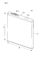
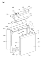
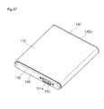
- the polymer battery pack 100 includes a bare cell 110, a holder frame 140 surrounding the bare cell 110, a protection circuit member 150 electrically connected to the bare cell 110 and fixed to the holder frame 140, and a cover 160 surrounding the protection circuit member 150 and fixed to the holder frame 140.
- the polymer battery pack 100 may further include an external label 170 surrounding the bare cell 110 and the holder frame 140, and a water sensitive paper 180 may be attached to the cover 160.
- the bare cell 110 is installed inside the holder frame 140.
- the protection circuit member 150 is installed outside the holder frame 140.
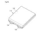
- the bare cell 110 includes a pouch type sheath 120, and an electrode assembly 130 and a polymer electrolyte (not shown) received inside the pouch type sheath 120.
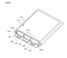
- the pouch type sheath 120 includes first and second surfaces 121 and 122 having two corresponding large areas, and third to six surfaces 123 to 126 having relatively small areas and connecting the first and second surfaces 121 and 122. Of the four surfaces 123 to 126, the third surface 123 corresponds to the front surface from which electrode tabs 134 and 135 are withdrawn.
- a first insulation layer (not shown) is formed on one surface of the pouch type sheath 120 and a second insulation layer (not shown) is formed on the opposite surface thereof, with a metal layer (not shown) being interposed therebetween.
- the metal layer may be made of one selected from aluminum, steel, stainless steel, and their equivalents.
- the first insulation layer may be made of one selected from cast polypropylene (CPP) and its equivalents and the second layer may be made of one selected from polyethylene terephthalate (PET) and its equivalents, but the present invention is not limited thereto.
- the electrode assembly 130 is formed by sequentially stacking or winding a positive electrode plate 131, a separator 133, and a negative electrode plate 132. Then, the electrode tabs 134 and 135 attached to the positive electrode plate 131 and the negative electrode plate 132 are withdrawn outside the electrode assembly 130 through the third surface 123 corresponding to the front surface of the pouch type sheath 120.
- the polymer electrolyte is a solid electrolyte or a gel electrolyte.
- the holder frame 140 has a rectangular frame structure that surrounds the outskirt areas of the bare cell 110.
- the holder frame 140 may be made of polyimide, polyurethane, or a plastic.
- the plastic may be a fiber-reinforced plastic (FRP) or an engineering plastic.
- the holder frame 140 may be made of a hot-melt resin or its equivalents using injection molding.
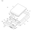
- the holder frame 140 includes two facing first and second frames 141 and 142, and third and fourth frames 143 and 144 formed relatively long at opposite ends of the first and second frames 141 and 142.
- the interval H between the first and second frames 141 and 142 corresponds to the height of the bare cell 110
- the interval W between the third and fourth frames 143 and 144 corresponds to the width of the bare cell.
- fixing bosses 141a for fixing the protection circuit member 150 are formed on both sides of the outer surface thereof.
- the fixing bosses 141a are cylindrical but their shapes are not limited thereto.
- Protrusions 141b coupled to the cover 160 are formed on the outer surface of the first frame 141 outside the fixing bosses 141a.
- Four supports 141c supporting the protection circuit member 150 are formed in parallel on the outer surface of the first frame 141. The supports 141c space the protection circuit member 150 apart from the first frame 141 by an interval.
- Guide ribs 142a are formed at both side edges of the second frame 142.
- the guide ribs 142a support the lower ends of the first and second surfaces 121 and 122 of the bare cell 110.
- the third and fourth frames 143 and 144 have the same shapes as those of the fourth and sixth surfaces 124 and 126 of the bare cell 110.
- the third and fourth frames 143 and 144 are rounded in order to protect the fourth and sixth surfaces 124 and 126 of the bare cell 110 from an external force.
- the protection circuit member 150 includes a protection circuit board 151, at least one electronic part 152 installed on one surface of the protection circuit board 151, electrode leads 153 and 154 installed on the surface of the protection circuit board 151 where the electronic part 152 is installed, electrically connected to the bare cell 110, and having opposite polarities, and several external terminals 155 installed on the surface of the protection circuit board 151 that is opposite to the surface where the electrode leads 153 and 154 are installed.
- the protection circuit board 151 has a plate-like shape, and fixing holes 151a are formed at right and left ends of the protection circuit board 151.
- the fixing bosses 141a of the first flame 141 are inserted into and coupled to the fixing holes 151a.
- the fixing holes 151a may have the shapes of recesses instead of those of holes.
- the electronic part 152 is installed on the surface of the protection circuit board 151 that faces the outer surface of the first frame 141. Accordingly, a space is formed between the first frame 141 and the protection circuit board 151 by the supports 141c formed in the first frame 141, and the electronic part 152 is located in the space.
- the electrode leads 153 and 154 are installed on the surface of the protection circuit board 151 that faces the outer surface of the first frame 141.
- the electrode leads 153 and 154 have the opposite polarities.
- the electrode leads 153 and 154 may be formed on one surface of the protection circuit board 151 in the form of conductive layers.
- the external terminals 155 are installed on the surface of the protection circuit board 151 that is opposite to the surface where the electrode leads 153 and 154 are installed and are electrically connected to the electrode leads 153 and 154.
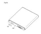
- the external terminals 155 are exposed to the outside through the cover 160 to cause current of the battery to flow to an external device.
- the cover 160 has an interior space and has a box-like shape one side surface of which is opened.
- the cover 160 may be made of polyimide, polyurethane, or a plastic.
- the cover 160 includes a body 161, coupling ribs 162 extending downward from the lower ends of side surfaces of the body 161, and recesses 163 formed at opposite ends of the body 161.
- the external terminals 155 of the protection circuit member 150 are exposed to the outside through the external terminal holes 161a.
- the coupling ribs 162 surround the upper ends of the first and second surfaces 121 and 122.
- the recesses 163 are coupled to the protrusions 141b of the first frame 141.
- the holder frame 140 and the cover 160 are firmly coupled to each other through the coupling structure.
- the external label 170 surrounds the first and second surfaces 121 and 122 of the bare cell 110 and the third and fourth frames 143 and 144 of the holder frame 140.
- the external label 170 is attached to the surfaces of the bare cell 110 and the holder frames 140 by coating an adhesive or a gluing agent.
- the external label 170 may be made of one selected from polyethylene terephthalate (PET) and its equivalents, but the material of the external label 170 is not limited thereto.
- PET polyethylene terephthalate
- the bare cell 110 is installed inside the holder frame 140.
- the third to sixth surfaces 123 to 126 of the pouch type sheath 120 are surrounded by the first to fourth frames 141 to 144 of the holder frame 140.
- the electrode tabs 134 and 135 of the bare cell 110 protrude to the outside of the first frame 141 and are welded to the electrode leads 153 and 154 formed on one surface of the protection circuit board 151.
- the protection circuit board 151 is installed in parallel to the first frame 141 of the holder frame 140, and the electrode leads 153 and 154 are formed on one surface of the protection circuit board 151 in the form of conductive layers.
- the first frame 141 is located between the bare cell 110 and the electrode tabs 134 and 135 in order to insulate the electrode tabs 134 and 135 from the bare cell 110.
- an insulation member such as an insulation tape is additionally attached to at least one of bare cell and electrode tabs in order to insulate the electrode tabs from the bare cell, increasing the number of parts and the number of manufacturing processes.
- the bare cell 110 and the protection circuit member 150 are assembled by the holder frame 140, with them being separated from each other, thereby enhancing assembling efficiency and reducing the number of additional parts.
- the protection circuit member 150 is coupled to the holder frame 140.
- the fixing bosses 141a formed at right and left ends of the first frame 141 are inserted into and fixed to the fixing holes 151a formed at right and left ends of the protection circuit board 151.
- the fixing holes 151a of the protection circuit board 151 have substantially C- or inverse C-shapes that are opened to the outside. Accordingly, even when the fixing bosses 141a of the first frame 141 do not accurately correspond to the fixing holes 151a, the polymer battery pack 100 can be smoothly assembled.
- a finished bare cell 110 is inspected, and electrode tabs 134 and 135 withdrawn outside the bare cell 110 are cut off to a predetermine length.
- the bare cell 110 is manufactured by receiving an electrode assembly (not shown) inside a pouch type sheath 120 and then fusing four surfaces thereof.
- the bare cell 110 is inserted into a holder frame 140. Once the bare cell 110 is coupled to the holder frame 140, the bare cell 110 is surrounded by first and second frames 141 and 142 and third and fourth frames 143 and 144. Thus, first and second surfaces 121 and 122 of the pouch 120 are exposed to the outside.
- Electrode tabs 134 and 135 protruding from the bare cell 110 to the outside of the holder frame 140 are welded to electrode leads 153 and 154 of the protection circuit member 150.
- the electrode tabs 134 and 135 protruding to the outside of the first frame 141 of the holder frame 140 are welded to the electrode leads 153 and 154 formed on one surface of the protection circuit board 151 in the form of insulation layers respectively. Accordingly, the bare cell 110 and the protection circuit member 150 are electrically connected to each other.
- the protection circuit member 150 is vertically folded toward the holder frame 140.
- the electrode tabs 134 and 135 of the bare cell 110 are also bent with the protection circuit board 151 being parallel to the first frame 141.
- fixing bosses 141a of the first frame 141 are inserted into fixing holes 151a of the protection circuit board 151, the protection circuit board 151 is fixed to the first frame 141. Accordingly, the protection circuit member 150 is firmly coupled to the holder frame 140.
- the protection circuit board 151 is supported by supports 141c of the first frame 141, and a space for locating an electronic part 152 is formed between the protection circuit board 151 and the first frame 141.
- the cover 160 is coupled to the holder frame 140. That is, the cover 160 is coupled to the first frame 141 of the holder frame 140. Then, protrusions 141b formed on the right and left sides of the first frame 141 are inserted into the recesses 163 formed on the right and left sides of the cover 160. If the cover 160 is coupled to the holder frame 140, external terminals 155 of the protection circuit member 150 are exposed to the outside through external terminal holes 161a formed in the body 161 of the cover 160.
- the external label 170 is attached to the outer peripheral surface of the bare cell 110.
- the first and second surfaces 121 and 122 are surrounded by the external label 170 with the bare cell 110 being coupled to the holder frame 140.
- the external label 170 fixes guide ribs 142a of the second frame 142 of the holder frame 140 and coupling ribs 162 of the cover 160 to the bare cell 110.
- the bare cell 110 is fixed to the inner side of the holder frame 140.
- the holder frame 140 protects the third to sixth narrow surfaces 123 to 126 of the bare cell 110. Accordingly, the holder frame 140 also functions as a bottom case protecting the lower end of the bare cell 110.
- the protection circuit member 150 is fixed to the outside of the holder frame 140. Accordingly, the holder frame 140 functions as a holder that couples the protection circuit member 150 to the bare cell 110.
- the cover 160 coupled to the holder frame 140 protects the protection circuit member 150 and exposes the external terminals 155 to the outside.
- the external label 170 finally surrounds the bare cell 110 and fixes the cover 160 to the bare cell 110 and the holder frame 140.
- FIG. 6 is an exploded perspective view of the polymer battery pack according to the embodiment of the present invention
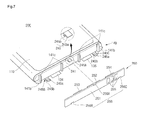
- FIG. 7 is a view illustrating a holder frame and a protection circuit member coupled to each other according to the embodiment of the present invention.
- the polymer battery pack 200 includes a bare cell 110, a holder frame 240 surrounding the bare cell 110, a protection circuit member 250 electrically connected to the bare cell 110 and fixed to the holder frame 240, and a cover 160 surrounding the protection circuit member 250.
- the polymer battery pack 200 may further include an external label 170 surrounding the bare cell 110 and the holder frame 240, and a water sensitive paper 180 may be attached to the cover 160.
- a water sensitive paper 180 may be attached to the cover 160.
- the polymer battery pack 200 according to the embodiment of the present invention provides a coupling structure of the holder frame 240 and the protection circuit member 250.
- the holder frame 240 includes two facing first and second frames 241 and 242, and third and fourth frames 243 and 244 integrally formed with opposite ends of the first and second frames 241 and 242 and longer than the first and second frames 241 and 242.
- Catching hooks 245 for fixing the protection circuit member 250 are formed on the outer surface of the first frame 241.
- the catching hooks 245 are formed at the center of one side edge of the first frame 241 and on opposite sides of the other edge thereof.
- Each catching hook 245 has an inclined portion 245a and a catching recess 245b.
- the inclined portion 245a is inclined toward the catching recess 245b so as to guide the protection circuit board 251 of the protection circuit member 250 to the catching recess 245b.
- the catching recess 245b has a size that allows insertion of the protection circuit board 251.
- the catching hooks 245 are a first catching hook 245A formed at the center of one side edge of the first frame 241 and second and third catching hooks 245B and 245C formed on opposite sides of the other edge thereof.
- the protection circuit member 250 includes a protection circuit board 251, an electronic part 252 and electrode leads 253 and 254 installed on one surface of the protection circuit board 251, and several external terminals 255 installed on the opposite surface of the protection circuit board 251.
- First to third catching recesses 256A to 256C to which the first to third catching hooks 245A to 245C of the first frame 241 are coupled are formed in the protection circuit board 251.
- the first catching recess 256A is formed at one side edge of the protection circuit board 251 at a position corresponding to the first catching hook 245A.
- the second and third catching recesses 256B and 256C are formed at the opposite side edge of the protection circuit board 251 at positions corresponding to the second and third catching hooks 245B and 245C.
- the bare cell 110 is installed inside the holder frame 240.
- the electrode tabs 134 and 135 of the bare cell 110 protrude to the outside of the holder frame 240 and are welded to the electrode leads 253 and 254 of the protection circuit member 250. Accordingly, the bare cell 110 and the protection circuit member 250 are electrically connected to each other.
- the protection circuit board 251 is folded toward the first frame 241, and the protection circuit member 250 is mechanically coupled to the holder frame 240.
- the first catching hook 245A formed at the center of the first frame 241 is coupled to the first catching recess 256A formed at the center of one side edge of the protection circuit board 251.
- the second and third catching hooks 245B and 245C formed at both ends of the opposite side edges of the first frame 241 are coupled to the second and third catching recesses 256B and 256C formed at both ends of the opposite side edge of the protection circuit board 251.
- the protection circuit board 251 is fixed to the first frame 241 at the center and the opposite ends thereof. Accordingly, the protection circuit member 250 is prevented from being easily separated from the holder frame 240 by an external impact. Moreover, the polymer battery pack 200 can be accurately and simply assembled.
- the protection circuit board 251 is coupled to the first frame 241 at three positions, but the present invention is not limited thereto. In other words, the protection circuit board 251 may be coupled to the first frame 241 only at the center thereof, or only at both ends thereof.
- coupling structures may be formed at upper and lower portions of the center of the protection circuit board 251, or at upper and lower portions of both ends thereof.
- the present invention does not limit the positions and numbers of coupling hooks and coupling recesses.
- FIG. 8 is an exploded perspective view of a polymer battery pack according to the embodiment of the present invention.
- the polymer battery pack 300 includes a bare cell 110, a holder frame 340 surrounding the bare cell 110, a protection circuit member 150 electrically connected to the bare cell 110 and fixed to the holder frame 340, and a cover 360 surrounding the protection circuit member 150.
- the polymer battery pack 300 provides a coupling structure of the holder frame 340 and the cover 360.
- the holder frame 340 includes two facing first and second frames 341 and 342, and third and fourth frames 343 and 344 integrally formed with opposite ends of the first and second frames 341 and 342 and longer than the first and second frames 341 and 342.
- the first frame 341 includes fixing bosses 341a formed at opposite sides of the outer surface thereof, protrusions 341b formed on the outer side of the fixing bosses 341a, four supports 341c formed on a surface of the first frame 341, and insertion bosses 341d formed at upper and lower ends of the supports 341 respectively.
- the protection circuit member 150 has fixing holes 151a formed at right and left ends of the protection circuit board 151 and coupled to the fixing bosses 141a of the first frame 141.
- the cover 360 includes a body 361, coupling ribs 362 extending downward from the lower ends of side surfaces of the body 361, recesses 363 formed at opposite ends of the body 361 and into which the protrusions 341b are inserted, and insertion holes 364 to which the insertion bosses 341d are coupled. Accordingly, eight insertion bosses 341d formed in the first frame 141 are inserted into the insertion holes 364 formed in the cover 360 in order to couple the cover 360 to the first frame 141.
- the bare cell 110 is installed inside the holder frame 340.
- the electrode tabs 134 and 135 of the bare cell 110 protrude outside the holder frame 340 and are welded to the electrode leads 153 and 154 of the protection circuit member 150.
- the bare cell 110 and the protection circuit member 150 are electrically connected to each other.
- the protection circuit board 151 is folded toward the first frame 341, and the fixing bosses 341a of the first frame 341 are inserted into and coupled to the fixing holes 151a of the protection circuit board 151. Then, the protection circuit board 151 is supported by the supports 341c.
- the cover 360 is coupled to the first frame 341 of the holder frame 340. Then, the protrusions 341c formed at opposite ends of the first frame 341 are inserted into the recesses 363 of the cover 360. Meanwhile, the insertion bosses 341d formed in the first frame 341 are inserted into and coupled to the insertion holes 364 of the cover 360.
- the coupling structure firmly couples the cover 360 to the first frame 341, thereby preventing the cover 360 from being separated from the first frame 341. Accordingly, the protection circuit member 150 is protected from an external impact by the cover 360, and is electrically insulated from the outside, thereby preventing a short circuit.
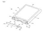
- FIG. 9 is an exploded perspective view illustrating an assembly of a holder frame and a protective circuit module of a polymer battery pack according to still another embodiment of the present invention
- FIG. 10 is a sectional view illustrating an assembly of the polymer battery pack according to still another embodiment of the present invention.
- a polymer battery pack 400 includes a bare cell 110, a holder frame 440 surrounding the bare cell 100, a protective circuit module 450 electrically connected to the bare cell 110 and fixed to the holder frame 440, and a cover 160 surrounding the protective circuit module 450.
- the bare cell 110 and the cover 160 of the polymer battery pack 400 are identical to those of the polymer battery pack according to the previous embodiment of the present invention, their description will be omitted.
- the holder frame 440 and the protective circuit module 450 are improved.
- the holder frame 440 includes first and second short frames 441 and 442 facing each other, and third and fourth long frames 443 and 444 longer than the first and second frames 441 and 442 and connecting the first and second frames 441 and 442 to each other.
- the first frame 441 includes a vertical portion 445 and a horizontal portion 446 horizontally extending from an end of the vertical portion 445.
- the vertical portion 445 has fixing protrusions 441a protruding from lateral ends of the vertical portion 445.
- the horizontal portion 446 is parallel to a direction where electrode 134 and 135 of the bare cell 110 are withdrawn.
- the second, third, and fourth frames 442, 443, and 444 form a space into which the bare cell 110 is seated.
- the second, third, and fourth framed 442, 443, and 444 may form a rounded space corresponding to the shape of the bare cell 110.
- the protective circuit module 450 includes a circuit board 451, an electric device 452 and electrode leads 453 and 454 which are mounted on a surface of the circuit board 451, and a plurality of external terminals 455 formed on an opposite surface of the circuit board 451.
- the protective circuit module 450 has fixing holes 451a formed in lateral ends of the circuit board 451 into which the fixing protrusions 441 are inserted.
- the protective circuit module 450 is fixed to the first frame 441 of the holder frame 440.
- the fixing protrusions 441a of the first frame 441 are inserted into the fixing holes 451a of the protective circuit module 450.
- circuit board 451 contacts closely to the vertical portion 445 of the first frame 441 so that the electrode leads 453 and 454 are electrically connected to the electrode tabs 134 and 135.
- the circuit board 451 is positioned on the top surface of the vertical portion 446 of the first frame 441.
- the horizontal portion 446 protects the circuit board 451 from an external shock.
Applications Claiming Priority (2)
| Application Number | Priority Date | Filing Date | Title |
|---|---|---|---|
| US10531308P | 2008-10-14 | 2008-10-14 | |
| US12/576,838 US8691429B2 (en) | 2008-10-14 | 2009-10-09 | Polymer battery pack and method for manufacturing the same |
Publications (2)
| Publication Number | Publication Date |
|---|---|
| EP2178134A1 true EP2178134A1 (fr) | 2010-04-21 |
| EP2178134B1 EP2178134B1 (fr) | 2017-11-29 |
Family
ID=41463083
Family Applications (1)
| Application Number | Title | Priority Date | Filing Date |
|---|---|---|---|
| EP09172907.9A Active EP2178134B1 (fr) | 2008-10-14 | 2009-10-13 | Bloc-batteries |
Country Status (5)
| Country | Link |
|---|---|
| US (1) | US8691429B2 (fr) |
| EP (1) | EP2178134B1 (fr) |
| JP (1) | JP5383418B2 (fr) |
| KR (1) | KR101156350B1 (fr) |
| CN (1) | CN101728580B (fr) |
Cited By (4)
| Publication number | Priority date | Publication date | Assignee | Title |
|---|---|---|---|---|
| EP2728642A1 (fr) * | 2012-11-01 | 2014-05-07 | Samsung SDI Co., Ltd. | Bloc-batteries |
| EP2378591B1 (fr) * | 2010-04-13 | 2019-02-27 | Samsung SDI Co., Ltd. | Batterie secondaire |
| EP3514856A1 (fr) * | 2014-08-14 | 2019-07-24 | Samsung SDI Co., Ltd. | Batterie |
| US11831027B2 (en) | 2021-09-27 | 2023-11-28 | Quantumscape Battery, Inc. | Electrochemical stack and method of assembly thereof |
Families Citing this family (27)
| Publication number | Priority date | Publication date | Assignee | Title |
|---|---|---|---|---|
| KR101023870B1 (ko) * | 2009-01-08 | 2011-03-22 | 삼성에스디아이 주식회사 | 파우치형 리튬 이차전지 |
| US9106042B2 (en) * | 2009-06-30 | 2015-08-11 | Motorola Solutions, Inc. | Battery connector system |
| US8686689B2 (en) * | 2009-11-30 | 2014-04-01 | Samsung Sdi Co., Ltd. | Battery assembly |
| US9350001B2 (en) * | 2010-07-09 | 2016-05-24 | Samsung Sdi Co., Ltd. | Battery pack for a lithium polymer Battery |
| KR101152471B1 (ko) | 2010-09-14 | 2012-06-01 | 삼성에스디아이 주식회사 | 배터리 팩 |
| US8748021B2 (en) * | 2010-10-19 | 2014-06-10 | Samsung Sdi Co., Ltd. | Battery module |
| KR101234240B1 (ko) * | 2011-02-11 | 2013-02-18 | 삼성에스디아이 주식회사 | 코어팩과 보호회로모듈 사이의 격벽을 포함하는 배터리 팩 |
| KR20130025165A (ko) | 2011-09-01 | 2013-03-11 | 삼성에스디아이 주식회사 | 충방전이 가능한 배터리 팩 |
| US9614208B2 (en) | 2011-10-10 | 2017-04-04 | Samsung Sdi Co., Ltd. | Battery pack with degassing cover and plate thereon |
| US9095077B2 (en) * | 2011-11-30 | 2015-07-28 | Apple Inc. | Graphene heat dissipators in portable electronic devices |
| KR101905081B1 (ko) * | 2011-12-09 | 2018-11-30 | 삼성에스디아이 주식회사 | 배터리 팩 |
| WO2013125748A1 (fr) * | 2012-02-23 | 2013-08-29 | 세방전지(주) | Boîtier pour élément de batterie utilisant une structure gravée |
| JP5966591B2 (ja) | 2012-05-15 | 2016-08-10 | ソニー株式会社 | バッテリパック |
| KR20140010633A (ko) * | 2012-07-16 | 2014-01-27 | 삼성에스디아이 주식회사 | 배터리 팩 |
| KR101650040B1 (ko) * | 2013-09-30 | 2016-08-22 | 주식회사 엘지화학 | 안정성이 향상된 전지팩 |
| KR102491159B1 (ko) * | 2015-08-17 | 2023-01-19 | 삼성에스디아이 주식회사 | 홀더를 갖는 전지 모듈 |
| CN117895056A (zh) * | 2016-02-01 | 2024-04-16 | 密执安州立大学董事会 | 固态电池的分段式电池单元架构 |
| JP6851805B2 (ja) * | 2016-12-16 | 2021-03-31 | 三洋電機株式会社 | 車両用のバッテリシステム |
| JP6418257B2 (ja) * | 2017-01-25 | 2018-11-07 | ソニー株式会社 | バッテリパック |
| KR102221780B1 (ko) * | 2017-05-04 | 2021-03-02 | 주식회사 엘지화학 | 배터리 팩 및 이의 제조방법 |
| US10615395B2 (en) | 2017-05-10 | 2020-04-07 | Apple Inc. | Battery cap with cut-out sections |
| CN111315746B (zh) | 2017-08-24 | 2022-11-29 | 光州科学技术院 | 色氨酸羟化酶抑制剂和包括该抑制剂的药物组合物 |
| KR102483682B1 (ko) * | 2017-10-30 | 2023-01-02 | 삼성에스디아이 주식회사 | 배터리 팩 |
| JP7049852B2 (ja) * | 2018-02-15 | 2022-04-07 | Fdk株式会社 | ケース及び素子パック |
| CN112952218B (zh) * | 2019-11-26 | 2022-12-13 | 东莞新能德科技有限公司 | 电池、电池的制造方法、电子装置及电池的测试方法 |
| JP7240372B2 (ja) * | 2020-12-21 | 2023-03-15 | プライムプラネットエナジー&ソリューションズ株式会社 | 蓄電モジュールおよびその製造方法 |
| CN216870763U (zh) * | 2022-01-25 | 2022-07-01 | 宁德时代新能源科技股份有限公司 | 采样装置、电池及用电设备 |
Citations (2)
| Publication number | Priority date | Publication date | Assignee | Title |
|---|---|---|---|---|
| US6218041B1 (en) * | 1997-11-05 | 2001-04-17 | U.S. Philips Corporation | Battery unit and a portable battery-operated device including such a battery unit |
| EP1524710A2 (fr) * | 2003-10-17 | 2005-04-20 | Sony Corporation | Structure de pile plate, bloc de piles et procédé de fabrication du bloc de piles |
Family Cites Families (20)
| Publication number | Priority date | Publication date | Assignee | Title |
|---|---|---|---|---|
| JPH1069894A (ja) | 1996-08-29 | 1998-03-10 | Sanyo Electric Co Ltd | パック電池 |
| CN1236507C (zh) * | 2000-03-17 | 2006-01-11 | Tdk株式会社 | 电化学装置 |
| JP2001307696A (ja) | 2000-04-21 | 2001-11-02 | Tookado:Kk | 電池パック |
| JP2003019569A (ja) * | 2001-07-04 | 2003-01-21 | At Battery:Kk | 抵抗溶接方法、それを用いて製造された電池パック |
| JP4283518B2 (ja) | 2002-10-07 | 2009-06-24 | Tdk株式会社 | 電気化学デバイス |
| US7348762B2 (en) * | 2003-05-01 | 2008-03-25 | Sony Corporation | Battery pack and method for producing battery pack |
| US8313856B2 (en) * | 2003-10-17 | 2012-11-20 | Sony Corporation | Structure of thin battery covered by outer packaging film, battery pack, and method for manufacturing battery pack |
| CN1922745B (zh) * | 2004-02-18 | 2010-12-01 | 株式会社Lg化学 | 含有保护电路板的整体帽盖组件以及包括该帽盖组件的二次电池 |
| JP4562426B2 (ja) | 2004-05-31 | 2010-10-13 | 三洋電機株式会社 | 電池パック |
| KR100601519B1 (ko) * | 2004-06-22 | 2006-07-19 | 삼성에스디아이 주식회사 | 파우치형 리튬 폴리머 전지 및 그 제조 방법 |
| KR100571247B1 (ko) * | 2004-10-18 | 2006-04-13 | 삼성에스디아이 주식회사 | 리튬이온 이차전지 |
| CN2772044Y (zh) * | 2004-11-18 | 2006-04-12 | 比亚迪股份有限公司 | 一种锂离子二次电池 |
| KR20060071813A (ko) | 2004-12-22 | 2006-06-27 | 남도현 | 이동통신 단말기용 전지팩 및 그 제조방법 |
| KR100877816B1 (ko) * | 2005-01-21 | 2009-01-12 | 주식회사 엘지화학 | 안전성이 향상된 전지팩 |
| KR100857034B1 (ko) * | 2005-03-25 | 2008-09-05 | 주식회사 엘지화학 | 난연성 접착부재를 포함하고 있는 전지 |
| KR100686814B1 (ko) * | 2005-04-26 | 2007-02-26 | 삼성에스디아이 주식회사 | 폴리머 배터리 팩 및 그 제조 방법 |
| JP2006324114A (ja) | 2005-05-18 | 2006-11-30 | Ngk Spark Plug Co Ltd | 薄型電池 |
| KR20080025437A (ko) | 2006-09-18 | 2008-03-21 | 주식회사 엘지화학 | 전극단자의 위치조절이 가능하고 안전성이 향상된 이차전지 |
| JP2009117263A (ja) | 2007-11-08 | 2009-05-28 | Sanyo Electric Co Ltd | パック電池 |
| KR101023870B1 (ko) * | 2009-01-08 | 2011-03-22 | 삼성에스디아이 주식회사 | 파우치형 리튬 이차전지 |
-
2009
- 2009-10-09 US US12/576,838 patent/US8691429B2/en active Active
- 2009-10-13 EP EP09172907.9A patent/EP2178134B1/fr active Active
- 2009-10-14 KR KR1020090097753A patent/KR101156350B1/ko active IP Right Grant
- 2009-10-14 JP JP2009237104A patent/JP5383418B2/ja active Active
- 2009-10-14 CN CN2009101795999A patent/CN101728580B/zh active Active
Patent Citations (2)
| Publication number | Priority date | Publication date | Assignee | Title |
|---|---|---|---|---|
| US6218041B1 (en) * | 1997-11-05 | 2001-04-17 | U.S. Philips Corporation | Battery unit and a portable battery-operated device including such a battery unit |
| EP1524710A2 (fr) * | 2003-10-17 | 2005-04-20 | Sony Corporation | Structure de pile plate, bloc de piles et procédé de fabrication du bloc de piles |
Cited By (5)
| Publication number | Priority date | Publication date | Assignee | Title |
|---|---|---|---|---|
| EP2378591B1 (fr) * | 2010-04-13 | 2019-02-27 | Samsung SDI Co., Ltd. | Batterie secondaire |
| EP2728642A1 (fr) * | 2012-11-01 | 2014-05-07 | Samsung SDI Co., Ltd. | Bloc-batteries |
| EP3514856A1 (fr) * | 2014-08-14 | 2019-07-24 | Samsung SDI Co., Ltd. | Batterie |
| US10411241B2 (en) | 2014-08-14 | 2019-09-10 | Samsung Sdi Co., Ltd. | Battery including an insulation spacer |
| US11831027B2 (en) | 2021-09-27 | 2023-11-28 | Quantumscape Battery, Inc. | Electrochemical stack and method of assembly thereof |
Also Published As
| Publication number | Publication date |
|---|---|
| CN101728580B (zh) | 2013-11-20 |
| EP2178134B1 (fr) | 2017-11-29 |
| US8691429B2 (en) | 2014-04-08 |
| US20100092859A1 (en) | 2010-04-15 |
| KR101156350B1 (ko) | 2012-06-13 |
| KR20100041689A (ko) | 2010-04-22 |
| JP5383418B2 (ja) | 2014-01-08 |
| CN101728580A (zh) | 2010-06-09 |
| JP2010097944A (ja) | 2010-04-30 |
Similar Documents
| Publication | Publication Date | Title |
|---|---|---|
| EP2178134B1 (fr) | Bloc-batteries | |
| KR101127603B1 (ko) | 버스 바 홀더 및 이를 구비하는 배터리 팩 | |
| EP2693516B1 (fr) | Bloc-batterie | |
| KR100928120B1 (ko) | 이차 전지 | |
| JP4571148B2 (ja) | Pcm金型およびそれを有するバッテリー | |
| KR101293591B1 (ko) | 이차전지 팩 | |
| EP2838135B1 (fr) | Bloc-batterie rechargeable | |
| KR101001315B1 (ko) | 우수한 에너지 밀도의 이차전지 팩 및 그것을 위한 pcm어셈블리 | |
| KR101240822B1 (ko) | 배터리 조립체 | |
| EP2693511B1 (fr) | Bloc-batterie | |
| US20150037619A1 (en) | Rechargeable battery pack | |
| US20140017551A1 (en) | Battery pack | |
| EP2273585B1 (fr) | Bloc-batteries | |
| KR101132166B1 (ko) | 제조 공정성이 향상된 이차전지 팩 및 ptc 소자 | |
| US10680213B2 (en) | Compact secondary battery module and secondary battery pack using same | |
| KR101182961B1 (ko) | 배터리 팩 | |
| KR101770330B1 (ko) | 접속용 만입홈이 형성되어 있는 이차전지 팩 | |
| US9362543B2 (en) | Battery pack | |
| KR101794943B1 (ko) | 체결 돌기 및 체결공이 형성되어 있는 전지팩 | |
| CN216085174U (zh) | 一种电池模组 | |
| KR20230031661A (ko) | 버스바 플레이트와 icb 조립체 간의 와이어 본딩 연결 구조를 개선한 배터리 모듈 및 이를 포함하는 배터리 팩 |
Legal Events
| Date | Code | Title | Description |
|---|---|---|---|
| PUAI | Public reference made under article 153(3) epc to a published international application that has entered the european phase |
Free format text: ORIGINAL CODE: 0009012 |
|
| 17P | Request for examination filed |
Effective date: 20091013 |
|
| AK | Designated contracting states |
Kind code of ref document: A1 Designated state(s): AT BE BG CH CY CZ DE DK EE ES FI FR GB GR HR HU IE IS IT LI LT LU LV MC MK MT NL NO PL PT RO SE SI SK SM TR |
|
| AX | Request for extension of the european patent |
Extension state: AL BA RS |
|
| 17Q | First examination report despatched |
Effective date: 20150714 |
|
| GRAP | Despatch of communication of intention to grant a patent |
Free format text: ORIGINAL CODE: EPIDOSNIGR1 |
|
| INTG | Intention to grant announced |
Effective date: 20170224 |
|
| GRAS | Grant fee paid |
Free format text: ORIGINAL CODE: EPIDOSNIGR3 |
|
| RAP1 | Party data changed (applicant data changed or rights of an application transferred) |
Owner name: SAMSUNG SDI CO., LTD. |
|
| GRAA | (expected) grant |
Free format text: ORIGINAL CODE: 0009210 |
|
| AK | Designated contracting states |
Kind code of ref document: B1 Designated state(s): AT BE BG CH CY CZ DE DK EE ES FI FR GB GR HR HU IE IS IT LI LT LU LV MC MK MT NL NO PL PT RO SE SI SK SM TR |
|
| REG | Reference to a national code |
Ref country code: GB Ref legal event code: FG4D |
|
| REG | Reference to a national code |
Ref country code: CH Ref legal event code: EP |
|
| REG | Reference to a national code |
Ref country code: AT Ref legal event code: REF Ref document number: 951153 Country of ref document: AT Kind code of ref document: T Effective date: 20171215 |
|
| REG | Reference to a national code |
Ref country code: IE Ref legal event code: FG4D |
|
| REG | Reference to a national code |
Ref country code: DE Ref legal event code: R096 Ref document number: 602009049592 Country of ref document: DE |
|
| REG | Reference to a national code |
Ref country code: NL Ref legal event code: MP Effective date: 20171129 |
|
| REG | Reference to a national code |
Ref country code: LT Ref legal event code: MG4D |
|
| REG | Reference to a national code |
Ref country code: AT Ref legal event code: MK05 Ref document number: 951153 Country of ref document: AT Kind code of ref document: T Effective date: 20171129 |
|
| PG25 | Lapsed in a contracting state [announced via postgrant information from national office to epo] |
Ref country code: SE Free format text: LAPSE BECAUSE OF FAILURE TO SUBMIT A TRANSLATION OF THE DESCRIPTION OR TO PAY THE FEE WITHIN THE PRESCRIBED TIME-LIMIT Effective date: 20171129 Ref country code: FI Free format text: LAPSE BECAUSE OF FAILURE TO SUBMIT A TRANSLATION OF THE DESCRIPTION OR TO PAY THE FEE WITHIN THE PRESCRIBED TIME-LIMIT Effective date: 20171129 Ref country code: LT Free format text: LAPSE BECAUSE OF FAILURE TO SUBMIT A TRANSLATION OF THE DESCRIPTION OR TO PAY THE FEE WITHIN THE PRESCRIBED TIME-LIMIT Effective date: 20171129 Ref country code: NO Free format text: LAPSE BECAUSE OF FAILURE TO SUBMIT A TRANSLATION OF THE DESCRIPTION OR TO PAY THE FEE WITHIN THE PRESCRIBED TIME-LIMIT Effective date: 20180228 Ref country code: ES Free format text: LAPSE BECAUSE OF FAILURE TO SUBMIT A TRANSLATION OF THE DESCRIPTION OR TO PAY THE FEE WITHIN THE PRESCRIBED TIME-LIMIT Effective date: 20171129 |
|
| PG25 | Lapsed in a contracting state [announced via postgrant information from national office to epo] |
Ref country code: LV Free format text: LAPSE BECAUSE OF FAILURE TO SUBMIT A TRANSLATION OF THE DESCRIPTION OR TO PAY THE FEE WITHIN THE PRESCRIBED TIME-LIMIT Effective date: 20171129 Ref country code: HR Free format text: LAPSE BECAUSE OF FAILURE TO SUBMIT A TRANSLATION OF THE DESCRIPTION OR TO PAY THE FEE WITHIN THE PRESCRIBED TIME-LIMIT Effective date: 20171129 Ref country code: BG Free format text: LAPSE BECAUSE OF FAILURE TO SUBMIT A TRANSLATION OF THE DESCRIPTION OR TO PAY THE FEE WITHIN THE PRESCRIBED TIME-LIMIT Effective date: 20180228 Ref country code: GR Free format text: LAPSE BECAUSE OF FAILURE TO SUBMIT A TRANSLATION OF THE DESCRIPTION OR TO PAY THE FEE WITHIN THE PRESCRIBED TIME-LIMIT Effective date: 20180301 Ref country code: AT Free format text: LAPSE BECAUSE OF FAILURE TO SUBMIT A TRANSLATION OF THE DESCRIPTION OR TO PAY THE FEE WITHIN THE PRESCRIBED TIME-LIMIT Effective date: 20171129 |
|
| PG25 | Lapsed in a contracting state [announced via postgrant information from national office to epo] |
Ref country code: NL Free format text: LAPSE BECAUSE OF FAILURE TO SUBMIT A TRANSLATION OF THE DESCRIPTION OR TO PAY THE FEE WITHIN THE PRESCRIBED TIME-LIMIT Effective date: 20171129 |
|
| PG25 | Lapsed in a contracting state [announced via postgrant information from national office to epo] |
Ref country code: CZ Free format text: LAPSE BECAUSE OF FAILURE TO SUBMIT A TRANSLATION OF THE DESCRIPTION OR TO PAY THE FEE WITHIN THE PRESCRIBED TIME-LIMIT Effective date: 20171129 Ref country code: CY Free format text: LAPSE BECAUSE OF FAILURE TO SUBMIT A TRANSLATION OF THE DESCRIPTION OR TO PAY THE FEE WITHIN THE PRESCRIBED TIME-LIMIT Effective date: 20171129 Ref country code: EE Free format text: LAPSE BECAUSE OF FAILURE TO SUBMIT A TRANSLATION OF THE DESCRIPTION OR TO PAY THE FEE WITHIN THE PRESCRIBED TIME-LIMIT Effective date: 20171129 Ref country code: DK Free format text: LAPSE BECAUSE OF FAILURE TO SUBMIT A TRANSLATION OF THE DESCRIPTION OR TO PAY THE FEE WITHIN THE PRESCRIBED TIME-LIMIT Effective date: 20171129 Ref country code: SK Free format text: LAPSE BECAUSE OF FAILURE TO SUBMIT A TRANSLATION OF THE DESCRIPTION OR TO PAY THE FEE WITHIN THE PRESCRIBED TIME-LIMIT Effective date: 20171129 |
|
| REG | Reference to a national code |
Ref country code: DE Ref legal event code: R097 Ref document number: 602009049592 Country of ref document: DE |
|
| PG25 | Lapsed in a contracting state [announced via postgrant information from national office to epo] |
Ref country code: IT Free format text: LAPSE BECAUSE OF FAILURE TO SUBMIT A TRANSLATION OF THE DESCRIPTION OR TO PAY THE FEE WITHIN THE PRESCRIBED TIME-LIMIT Effective date: 20171129 Ref country code: RO Free format text: LAPSE BECAUSE OF FAILURE TO SUBMIT A TRANSLATION OF THE DESCRIPTION OR TO PAY THE FEE WITHIN THE PRESCRIBED TIME-LIMIT Effective date: 20171129 Ref country code: PL Free format text: LAPSE BECAUSE OF FAILURE TO SUBMIT A TRANSLATION OF THE DESCRIPTION OR TO PAY THE FEE WITHIN THE PRESCRIBED TIME-LIMIT Effective date: 20171129 Ref country code: SM Free format text: LAPSE BECAUSE OF FAILURE TO SUBMIT A TRANSLATION OF THE DESCRIPTION OR TO PAY THE FEE WITHIN THE PRESCRIBED TIME-LIMIT Effective date: 20171129 |
|
| REG | Reference to a national code |
Ref country code: FR Ref legal event code: PLFP Year of fee payment: 10 |
|
| PLBE | No opposition filed within time limit |
Free format text: ORIGINAL CODE: 0009261 |
|
| STAA | Information on the status of an ep patent application or granted ep patent |
Free format text: STATUS: NO OPPOSITION FILED WITHIN TIME LIMIT |
|
| 26N | No opposition filed |
Effective date: 20180830 |
|
| PG25 | Lapsed in a contracting state [announced via postgrant information from national office to epo] |
Ref country code: SI Free format text: LAPSE BECAUSE OF FAILURE TO SUBMIT A TRANSLATION OF THE DESCRIPTION OR TO PAY THE FEE WITHIN THE PRESCRIBED TIME-LIMIT Effective date: 20171129 |
|
| REG | Reference to a national code |
Ref country code: CH Ref legal event code: PL |
|
| REG | Reference to a national code |
Ref country code: BE Ref legal event code: MM Effective date: 20181031 |
|
| PG25 | Lapsed in a contracting state [announced via postgrant information from national office to epo] |
Ref country code: LU Free format text: LAPSE BECAUSE OF NON-PAYMENT OF DUE FEES Effective date: 20181013 Ref country code: MC Free format text: LAPSE BECAUSE OF FAILURE TO SUBMIT A TRANSLATION OF THE DESCRIPTION OR TO PAY THE FEE WITHIN THE PRESCRIBED TIME-LIMIT Effective date: 20171129 |
|
| REG | Reference to a national code |
Ref country code: IE Ref legal event code: MM4A |
|
| PG25 | Lapsed in a contracting state [announced via postgrant information from national office to epo] |
Ref country code: BE Free format text: LAPSE BECAUSE OF NON-PAYMENT OF DUE FEES Effective date: 20181031 Ref country code: LI Free format text: LAPSE BECAUSE OF NON-PAYMENT OF DUE FEES Effective date: 20181031 Ref country code: CH Free format text: LAPSE BECAUSE OF NON-PAYMENT OF DUE FEES Effective date: 20181031 |
|
| PG25 | Lapsed in a contracting state [announced via postgrant information from national office to epo] |
Ref country code: IE Free format text: LAPSE BECAUSE OF NON-PAYMENT OF DUE FEES Effective date: 20181013 |
|
| PG25 | Lapsed in a contracting state [announced via postgrant information from national office to epo] |
Ref country code: MT Free format text: LAPSE BECAUSE OF NON-PAYMENT OF DUE FEES Effective date: 20181013 |
|
| PG25 | Lapsed in a contracting state [announced via postgrant information from national office to epo] |
Ref country code: TR Free format text: LAPSE BECAUSE OF FAILURE TO SUBMIT A TRANSLATION OF THE DESCRIPTION OR TO PAY THE FEE WITHIN THE PRESCRIBED TIME-LIMIT Effective date: 20171129 |
|
| PG25 | Lapsed in a contracting state [announced via postgrant information from national office to epo] |
Ref country code: PT Free format text: LAPSE BECAUSE OF FAILURE TO SUBMIT A TRANSLATION OF THE DESCRIPTION OR TO PAY THE FEE WITHIN THE PRESCRIBED TIME-LIMIT Effective date: 20171129 |
|
| PG25 | Lapsed in a contracting state [announced via postgrant information from national office to epo] |
Ref country code: MK Free format text: LAPSE BECAUSE OF NON-PAYMENT OF DUE FEES Effective date: 20171129 Ref country code: HU Free format text: LAPSE BECAUSE OF FAILURE TO SUBMIT A TRANSLATION OF THE DESCRIPTION OR TO PAY THE FEE WITHIN THE PRESCRIBED TIME-LIMIT; INVALID AB INITIO Effective date: 20091013 |
|
| PG25 | Lapsed in a contracting state [announced via postgrant information from national office to epo] |
Ref country code: IS Free format text: LAPSE BECAUSE OF FAILURE TO SUBMIT A TRANSLATION OF THE DESCRIPTION OR TO PAY THE FEE WITHIN THE PRESCRIBED TIME-LIMIT Effective date: 20180329 |
|
| REG | Reference to a national code |
Ref country code: DE Ref legal event code: R079 Ref document number: 602009049592 Country of ref document: DE Free format text: PREVIOUS MAIN CLASS: H01M0002040000 Ipc: H01M0050147000 |
|
| P01 | Opt-out of the competence of the unified patent court (upc) registered |
Effective date: 20230528 |
|
| PGFP | Annual fee paid to national office [announced via postgrant information from national office to epo] |
Ref country code: FR Payment date: 20230929 Year of fee payment: 15 |
|
| PGFP | Annual fee paid to national office [announced via postgrant information from national office to epo] |
Ref country code: GB Payment date: 20231006 Year of fee payment: 15 |
|
| PGFP | Annual fee paid to national office [announced via postgrant information from national office to epo] |
Ref country code: DE Payment date: 20230929 Year of fee payment: 15 |