EP2177698A1 - Verriegelungsvorrichtung für Wertbehälter. - Google Patents
Verriegelungsvorrichtung für Wertbehälter. Download PDFInfo
- Publication number
- EP2177698A1 EP2177698A1 EP09401017A EP09401017A EP2177698A1 EP 2177698 A1 EP2177698 A1 EP 2177698A1 EP 09401017 A EP09401017 A EP 09401017A EP 09401017 A EP09401017 A EP 09401017A EP 2177698 A1 EP2177698 A1 EP 2177698A1
- Authority
- EP
- European Patent Office
- Prior art keywords
- bolt
- adjusting
- lock
- axis
- screw
- Prior art date
- Legal status (The legal status is an assumption and is not a legal conclusion. Google has not performed a legal analysis and makes no representation as to the accuracy of the status listed.)
- Granted
Links
Images



Classifications
-
- E—FIXED CONSTRUCTIONS
- E05—LOCKS; KEYS; WINDOW OR DOOR FITTINGS; SAFES
- E05B—LOCKS; ACCESSORIES THEREFOR; HANDCUFFS
- E05B65/00—Locks or fastenings for special use
- E05B65/0075—Locks or fastenings for special use for safes, strongrooms, vaults, fire-resisting cabinets or the like
-
- E—FIXED CONSTRUCTIONS
- E05—LOCKS; KEYS; WINDOW OR DOOR FITTINGS; SAFES
- E05B—LOCKS; ACCESSORIES THEREFOR; HANDCUFFS
- E05B63/00—Locks or fastenings with special structural characteristics
- E05B63/0017—Locks with sliding bolt without provision for latching
Definitions
- the invention relates to a device for locking and unlocking a lid on a base part of a valuable container, in particular a cash container, with a linearly displaceable between an unlocking position and a locking position latch and an actuatable via a lock actuator for adjusting the bolt.
- Object of the present invention is therefore to develop a device for locking and unlocking a lid on a base part of a valuable container such that a compact and space-saving rotary / linear motion conversion is possible.
- the invention in connection with the preamble of claim 1, characterized in that the actuator is designed as a rotatably connected to the lock and rotatable about a worm axis adjusting worm, a radially projecting from the screw axis and in a direction with a axial direction and having a circumferential direction component extending actuator which is in engagement with a guide element of the bolt.
- an adjusting screw is provided as actuator for actuating a bolt of the device, which acts on a radially projecting from a screw axis, extending in the axial and circumferential direction of the adjusting screw actuator on a guide element of the bolt such that by pressing the lock of the bolt between the unlocking and locking position and vice versa is displaced.
- the basic idea of the invention is to provide a mechanical motion conversion element, wherein the rotational movement of the adjusting screw is converted into a linear movement of the bolt by the engaged position of the adjusting element of the adjusting screw with the guide element of the bolt.
- the adjusting element of the adjusting worm is designed as a positioning web, which extends helically in an acute or obtuse circumferential angle region around the worm axis. Due to the slope and / or length of the positioning bar, the linear displacement of the bolt can be specified.
- the guide element of the bolt is designed as a straight guide groove, which is arranged inclined with respect to the direction of displacement of the bolt.
- the positioning bar can engage in the guide groove and be surrounded with play in the same so that with little effort of the user, the rotational movement of the lock can be converted into a longitudinal movement of the bolt.
- the positioning bar is arranged on the outside on a lateral surface of the adjusting worm, wherein a height of the positioning bar is matched to the depth of the guide groove of the bolt, that the lateral surface does not come to rest on the bolt.
- a smooth motion conversion can be made possible.
- the bolt is slidably coupled via a linear guide with a latch receiving device, wherein the latch receiving device is arranged fixed in position in the base part of the valuable container.
- the latch receiving device is latching and / or connected by screw connection to the base part.
- the device is arranged in a corner region of the base part, wherein a bolt receiving direction and the bolt and the adjusting worm and the lock are designed to be plugged together.
- a bolt receiving direction and the bolt and the adjusting worm and the lock are designed to be plugged together.
- a closure device can be used to lock any container.
- the containers are designed as a valuable container whose contents should be protected against external access.
- the valuable container is designed as a money container in which bank notes can be wound up or unwound by means of a conveyor belt. By such a reel storage a simple storage and dispensing of banknotes is possible.
- a money container 1 is shown with a base part 2 and a lid 3 to form a housing thereof.
- the lid 3 is connected via a hinge, not shown, pivotally connected to the base part 2, wherein by means of a closure device 4 according to the invention the lid 3 with the base part 2 can be closed.
- the closure device 4 is arranged in a lower corner region 5 of the base part 2 and extends substantially from a front side 6 of the base part 2 to a rear side 7 thereof.
- a bore is provided, through which a lock 8 designed as a cylinder lock can be partially pushed through from the front side 6 of the base part 2.
- the cylinder lock 8 has on a side facing the insertion slot 9 for the key side a hollow cylindrical stub 10 which is in rotational engagement with a corresponding stub axle 11 of a subsequent actuator 12.
- the actuator 12 is formed as an adjusting worm, which is insertable with the stub axle 11 in the hollow cylindrical stump 10 of the lock 8, so that a worm axis 13 of the adjusting worm 12 is arranged coaxially to a rotational axis of the lock 8.
- the adjusting worm 12 acts via an adjusting element 14 on an elongate latch 15 such that it is linearly adjustable along a displacement direction V as a function of the rotational position of the lock 8 or the adjusting worm 12 between an unlocking position and a locking position.
- the bolt 15 is plate-shaped and is displaceable via a linear guide 17 in the displacement direction V. stored in an elongated latch receiving device 16.
- the bolt 15 has two mutually spaced in the displacement direction V elongated holes 18, in each of which a pin 19 of the positionally fixed latch receiving device 16 are performed with play.
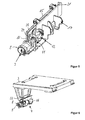
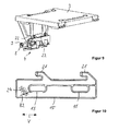
- the latch 15 at two spaced apart hooks 21 at an upper longitudinal edge 20, which engage in the locking position of the bolt 15, a flange 22 of the lid 3 (see FIG. 6 ) and in the unlocked position out of engagement with the flanges 22 of the lid 3 are (see FIG. 9 ).
- the adjusting element 14 of the adjusting screw 12 is formed as a running with an axial direction and with a circumferential directional adjusting web, which protrudes radially from a lateral surface 23 of the adjusting screw 12.
- the setting web 14 extends helically in an obtuse peripheral angular range about the screw axis 13.
- the lateral surface 23 has from the screw axis 13 at such a distance that the positioning web 14 at a 90 ° twist of the lock 8 has such a slope that the Rotary movement of the screw 12 can be transferred without jerking on a trained as a guide groove 24 guide member 15 of the bolt.
- the guide groove 24 is formed in a straight line and extends at an acute angle to the direction of displacement V of the bolt 15. In the working position of the device, the positioning bar 14 is in engagement with the guide groove 24, so that in dependence on the rotational position of the adjusting screw 12 of the bolt 15 can be brought into the unlocking or locking position.
- the adjusting screw 12 is partially open, wherein the lateral surface 23 extends only on one half side of the screw axis 13.
- the lateral surface 23 is arranged at a distance from one another by means of radial support ribs 25 arranged at a distance from each other in the axial direction relative to the screw axis 13.
- the helical positioning bar 14 extends continuously and diagonally between a front first corner region 26 of the lateral surface 23 and a rear second corner region 27 thereof.
- the positioning bar 14 preferably has a height H such that the jacket surface 23 is arranged at a distance from the bolt 15 in the assembly position.
- the depth of the guide groove 24 is thus preferably smaller than the height H of the support web 14. This ensures the smoothest possible motion conversion.
- a width B1 of the positioning bar 14 is matched to a width B2 of the guide groove 24 such that the positioning bar 14 is mounted in the guide groove 24 with little play.
- the rotational movement of the screw 12 can thus be transmitted directly to the linear movement of the bolt 14.
- An undesirable sticking of the support bar 14 in the guide groove 24 can be prevented beyond.
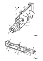
- a portion of the positioning bar 14 in the guide groove 24 a In the locking position is a front end portion 28 of the actuating element 14 in the guide groove 24, see FIG. 5 ; in the unlocked position is a rear end portion 29 of the adjusting bar 14 in the guide groove 24, see FIG. 8 ,
- the latch receiving device 16 the latch 15, the adjusting screw 12 and the lock 8 are arranged to be plugged together.
- the latch receiving device 16 is preferably latching and / or connected by screw connection with the base part 2.
- the bolt receiving device 16, the bolt 15 and the adjusting worm 12 are preferably made of a plastic material.
- the positioning bar 14 may also extend along an obtuse or obtuse peripheral angular range around the screw axis 13.
Landscapes
- Engineering & Computer Science (AREA)
- Structural Engineering (AREA)
- Closures For Containers (AREA)
- Lock And Its Accessories (AREA)
Abstract
Description
- Die Erfindung betrifft eine Vorrichtung zum Verriegeln und Entriegeln eines Deckels an einem Basisteil eines Wertbehälters, insbesondere eines Geldbehälters, mit einem zwischen einer Entriegelungsstellung und einer Verriegelungsstellung linear verschiebbaren Riegel und mit einem über ein Schloss betätigbares Stellorgan zum Verstellen des Riegels.
- Zum Verriegeln und Entriegeln des Deckels eines Wertbehälters ist es aus der
DE 10 2005 001 355 B4 bekannt, einen linear verschiebbaren Riegel vorzusehen, der zwischen einer Entriegelungsstellung und einer Verriegelungsstellung über ein Stellorgan verstellbar ist. Ein Schloss wirkt auf das Stellorgan derart ein, dass der Riegel senkrecht zur Achse des Schlosses verstellt wird, was einen relativ aufwändigen und voluminösen Verschlussmechanismus erfordert. - Aufgabe der vorliegenden Erfindung ist es daher, eine Vorrichtung zum Verriegeln und Entriegeln eines Deckels an einem Basisteil eines Wertbehälters derart weiterzubilden, dass eine kompakte und Platz sparende Dreh-/Linearbewegungsumwandlung ermöglicht wird.
- Zur Lösung der Aufgabe ist die Erfindung in Verbindung mit dem Oberbegriff des Patentanspruchs 1 dadurch gekennzeichnet, dass das Stellorgan als eine drehfest mit dem Schloss verbundene und um eine Schneckenachse drehbare Stellschnecke ausgebildet ist, die ein radial von der Schneckenachse abragendes und ein in Richtung mit einer Axialrichtungs-und mit einer Umfangsrichtungskomponente verlaufendes Stellelement aufweist, das mit einem Führungselement des Riegels in Eingriff steht.
- Nach der Erfindung ist als Stellorgan zur Betätigung eines Riegels der Vorrichtung eine Stellschnecke vorgesehen, die über ein radial von einer Schneckenachse abragendes, in Axial- und Umfangsrichtung der Stellschnecke verlaufendes Stellelement auf ein Führungselement des Riegels derart einwirkt, dass durch Betätigen des Schlosses der Riegel zwischen der Entriegelungs- und Verriegelungsstellung und umgekehrt verschiebbar ist. Grundgedanke der Erfindung ist es, ein mechanisches Bewegungsumwandlungsorgan vorzusehen, wobei durch die Eingriffstellung des Stellelementes der Stellschnecke mit dem Führungselement des Riegels die Drehbewegung der Stellschnecke in eine Linearbewegung des Riegels umgewandelt wird. Vorteilhaft ergibt sich hierdurch eine robuste und Platz sparende Verschlussmechanik.
- Nach einer bevorzugten Ausführungsform der Erfindung ist das Stellelement der Stellschnecke als ein Stellsteg ausgebildet, der sich wendelförmig in einem spitzen oder stumpfen Umfangswinkelbereich um die Schneckenachse erstreckt. Durch die Steigung und/oder Länge des Stellsteges kann der lineare Verschiebeweg des Riegels vorgegeben werden.
- Nach einer Weiterbildung der Erfindung ist das Führungselement des Riegels als eine gerade Führungsnut ausgebildet, die bezüglich der Verschieberichtung des Riegels geneigt angeordnet ist. Vorteilhaft kann der Stellsteg in die Führungsnut eingreifen und mit Spiel in derselben so eingefasst sein, dass mit geringem Kraftaufwand des Benutzers die Drehbewegung des Schlosses in eine Längsbewegung des Riegels umgewandelt werden kann.
- Nach einer Weiterbildung der Erfindung ist der Stellsteg außenseitig auf einer Mantelfläche der Stellschnecke angeordnet, wobei eine Höhe des Stellsteges derart auf die Tiefe der Führungsnut des Riegels abgestimmt ist, dass die Mantelfläche nicht an dem Riegel zur Anlage kommt. Hierdurch kann eine reibungsfreie Bewegungsumwandlung ermöglicht werden. Dadurch, dass sich der Stellsteg wendelförmig und vorzugsweise einstückig auf der Mantelfläche erstreckt, wird ermöglicht, dass eine Verstellung des Riegels zwischen der Verriegelungs- und Entriegelungsstellung durch Verdrehen der Stellschnecke um einen spitzen bzw. stumpfen Winkel ermöglicht wird.
- Nach einer Weiterbildung der Erfindung ist der Riegel über eine Linearführung mit einer Riegelaufnahmeeinrichtung verschiebbar gekoppelt, wobei die Riegelaufnahmeeinrichtung lagefest in dem Basisteil des Wertbehälters angeordnet ist. Vorzugsweise ist die Riegelaufnahmeeinrichtung rastend und/oder durch Schraubverbindung mit dem Basisteil verbunden. Vorteilhaft kann hierdurch auf einfache Weise eine Integration einer erfindungsgemäßen Verschlussvorrichtung in einem Wertbehälter ermöglicht werden.
- Nach einer Weiterbildung der Erfindung ist die Vorrichtung in einem Eckbereich des Basisteils angeordnet, wobei eine Riegelaufnahmerichtung und der Riegel sowie die Stellschnecke und das Schloss zusammensteckbar ausgebildet sind. Vorteilhaft kann hierdurch die Montage der Vorrichtung an dem Wertbehälter ohne Zuhilfenahme eines Werkzeugs vereinfacht werden.
- Ein Ausführungsbeispiel der Erfindung wird nachfolgend anhand der Zeichnungen näher erläutert.
- Es zeigen:
- Figur 1
- eine perspektivische Vorderansicht eines Wertbe- hälters mit einem unteren Basisteil und einem De- ckel,
- Figur 2
- eine perspektivische Vorderansicht des Basisteils des Wertbehälters mit einer integrierten Ver- schlussvorrichtung,
- Figur 3
- eine perspektivische Rückansicht des Basisteils der integrierten Verschlussvorrichtung,
- Figur 4
- eine perspektivische Darstellung der erfindungs- gemäßen Vorrichtung gemäß Einzelheit X in
Figur 3 von einer ersten Seite, wobei sich ein Riegel der Vorrichtung in einer Verriegelungsstellung befin- det, - Figur 5
- eine perspektivische Darstellung der Vorrichtung von einer zu
Figur 4 gegenüberliegenden zweiten Seite der Vorrichtung, wobei sich der Riegel der Vorrichtung in der Verriegelungsstellung befin- det, - Figur 6
- eine perspektivische Darstellung der erfindungs- gemäßen Vorrichtung von der Vorderseite, wobei in der Verriegelungsstellung des Riegels Haken des- selben einen Flansch des Deckels hintergreifen,
- Figur 7
- eine perspektivische Darstellung der erfindungs- gemäßen Vorrichtung von der zweiten Seite, wobei sich der Riegel der Vorrichtung in einer Entrie- gelungsstellung befindet,
- Figur 8
- eine perspektivische Darstellung der Vorrichtung von der zu
Figur 7 gegenüberliegenden ersten Sei- te der Vorrichtung, wobei sich der Riegel in der Entriegelungsstellung befindet, - Figur 9
- eine perspektivische Darstellung der erfindungs- gemäßen Vorrichtung von der zweiten Seite, wobei in der Entriegelungsstellung des Riegels die Ha- ken desselben seitlich versetzt zu den Flanschen des Deckels angeordnet sind,
- Figur 10
- eine Seitenansicht des Riegels,
- Figur 11
- eine perspektivische Darstellung einer Stell- schnecke der Vorrichtung von einer ersten Seite und
- Figur 12
- eine perspektivische Darstellung einer Stell- schnecke der Vorrichtung von einer zweiten Seite.
- Eine erfindungsgemäße Verschlussvorrichtung kann zur Verriegelung jeglicher Behälter eingesetzt werden. Vorzugsweise sind die Behälter als Wertbehälter ausgebildet, deren Inhalt vor äußerem Zugriff geschützt sein soll. Im vorliegenden Ausführungsbeispiel ist der Wertbehälter als ein Geldbehälter ausgebildet, in dem Banknoten mittels eines Transportbandes auf- bzw. abwickelbar sind. Durch einen solchen Rollenspeicher wird ein einfaches Einspeichern bzw. Ausgeben von Banknoten ermöglicht.
- In den
Figuren 1 bis 3 ist ein Geldbehälter 1 mit einem Basisteil 2 und einem Deckel 3 zur Bildung eines Gehäuses desselben dargestellt. Der Deckel 3 ist über ein nicht dargestelltes Scharnier schwenkbar mit dem Basisteil 2 verbunden, wobei mittels einer erfindungsgemäßen Verschlussvorrichtung 4 der Deckel 3 mit dem Basisteil 2 verschließbar ist. Wie aus denFiguren 2 und3 zu ersehen ist, ist die Verschlussvorrichtung 4 in einem unteren Eckbereich 5 des Basisteils 2 angeordnet und erstreckt sich im Wesentlichen von einer Vorderseite 6 des Basisteils 2 zu einer Rückseite 7 desselben. In einem unteren Eckbereich der Vorderseite 6 ist eine Bohrung vorgesehen, durch die ein als Zylinderschloss ausgebildetes Schloss 8 von der Vorderseite 6 des Basisteils 2 her teilweise durchsteckbar ist. Das Zylinderschloss 8 weist auf einer dem Einführschlitz 9 für den Schlüssel gegenüberliegenden Seite einen hohlförmigen Zylinderstumpf 10 auf, der in Dreheingriff mit einem korrespondierenden Achsenstumpf 11 eines sich anschließenden Stellorgans 12 befindet. Das Stellorgan 12 ist als eine Stellschnecke ausgebildet, die mit dem Achsenstumpf 11 in den hohlförmigen Zylinderstumpf 10 des Schlosses 8 einsteckbar ist, so dass eine Schneckenachse 13 der Stellschnecke 12 koaxial zu einer Drehachse des Schlosses 8 angeordnet ist. - Die Stellschnecke 12 wirkt über ein Stellelement 14 auf einen langgestreckten Riegel 15 derart ein, dass dieser in Abhängigkeit von der Drehstellung des Schlosses 8 bzw. der Stellschnecke 12 zwischen einer Entriegelungsstellung und einer Verriegelungsstellung linear entlang einer Verschieberichtung V verstellbar ist.
- Der Riegel 15 ist plattenförmig ausgebildet und ist über eine Linearführung 17 verschiebbar in Verschieberichtung V in einer langgestreckten Riegelaufnahmeeinrichtung 16 gelagert. Zu diesem Zweck weist der Riegel 15 zwei in Verschieberichtung V beabstandet zueinander angeordnete Langlöcher 18 auf, in denen jeweils ein Zapfen 19 der lagefest angeordneten Riegelaufnahmeeinrichtung 16 mit Spiel geführt sind. Ferner weist der Riegel 15 an einem oberen Längsrand 20 zwei beabstandet zueinander angeordnete Haken 21 auf, die in der Verriegelungsstellung des Riegels 15 einen Flansch 22 des Deckels 3 hintergreifen (siehe
Figur 6 ) und die in der Entriegelungsstellung außer Eingriff mit den Flanschen 22 des Deckels 3 sind (sieheFigur 9 ). - Zum Verstellen des Riegels 15 zwischen der Verriegelungsstellung und der Entriegelungsstellung und vice versa ist das Stellelement 14 der Stellschnecke 12 als ein mit einer Axialrichtungs- und mit einer Umfangsrichtungskomponente verlaufender Stellsteg ausgebildet, der radial von einer Mantelfläche 23 der Stellschnecke 12 abragt. Wie insbesondere aus den
Figuren 11 und 12 ersichtlich ist, erstreckt sich der Stellsteg 14 wendelförmig in einem stumpfen Umfangswinkelbereich um die Schneckenachse 13. Die Mantelfläche 23 hat von der Schneckenachse 13 einen solchen Abstand, dass der Stellsteg 14 bei einer 90°-Verdrehung des Schlosses 8 eine solche Steigung aufweist, dass die Drehbewegung der Schnecke 12 ruckfrei auf ein als Führungsnut 24 ausgebildetes Führungselement des Riegels 15 übertragen werden kann. Die Führungsnut 24 ist geradlinig ausgebildet und erstreckt sich in einem spitzen Neigungswinkel zu der Verschieberichtung V des Riegels 15. In der Arbeitsstellung der Vorrichtung befindet sich der Stellsteg 14 in Eingriff mit der Führungsnut 24, so dass in Abhängigkeit von der Drehstellung der Stellschnecke 12 der Riegel 15 in die Entriegelungs- oder Verriegelungsstellung bringbar ist. - Wie aus den
Figuren 11 und 12 ersichtlich ist, ist die Stellschnecke 12 teilweise offen ausgebildet, wobei sich die Mantelfläche 23 lediglich auf einer Halbseite der Schneckenachse 13 erstreckt. Die Mantelfläche 23 ist über in Axialrichtung beabstandet zueinander angeordnete radiale Stützrippen 25 gegenüber der Schneckenachse 13 beabstandet angeordnet. - Der wendelförmige Stellsteg 14 erstreckt sich durchgehend und diagonal zwischen einem vorderen ersten Eckbereich 26 der Mantelfläche 23 und einem hinteren zweiten Eckbereich 27 derselben. Der Stellsteg 14 weist vorzugsweise eine solche Höhe H auf, dass die Mantelfläche 23 in der Montagestellung beabstandet zu dem Riegel 15 angeordnet ist. Die Tiefe der Führungsnut 24 ist somit vorzugsweise kleiner als die Höhe H des Stützsteges 14. Damit wird eine möglichst reibungsfreie Bewegungsumwandlung sichergestellt.
- Eine Breite B1 des Stellstegs 14 ist derart auf eine Breite B2 der Führungsnut 24 abgestimmt, dass der Stellsteg 14 mit geringem Spiel in der Führungsnut 24 gelagert ist. Die Drehbewegung der Schnecke 12 kann somit unmittelbar auf die Linearbewegung des Riegels 14 übertragen werden. Ein unerwünschtes Feststecken des Stützsteges 14 in der Führungsnut 24 kann darüber hinaus verhindert werden. In Abhängigkeit von der Drehstellung der Stellschnecke 12 taucht somit ein Teilabschnitt des Stellsteges 14 in die Führungsnut 24 ein. In der Verriegelungsstellung befindet sich ein vorderer Endabschnitt 28 des Stellelementes 14 in der Führungsnut 24, siehe
Figur 5 ; in der Entriegelungsstellung befindet sich ein hinterer Endabschnitt 29 des Stellsteges 14 in der Führungsnut 24, sieheFigur 8 . - Vorzugsweise sind die Riegelaufnahmeeinrichtung 16, der Riegel 15, die Stellschnecke 12 und das Schloss 8 zusammensteckbar angeordnet. Die Riegelaufnahmeeinrichtung 16 ist vorzugsweise rastend und/oder mittels Schraubverbindung mit dem Basisteil 2 verbunden.
- Die Riegelaufnahmeeinrichtung 16, der Riegel 15 sowie die Stellschnecke 12 sind vorzugsweise aus einem Kunststoffmaterial hergestellt.
- Nach einer nicht dargestellten alternativen Ausführungsform kann sich der Stellsteg 14 auch entlang eines stumpfen oder überstumpfen Umfangswinkelbereiches um die Schneckenachse 13 erstrecken.
-
- 1
- Geldbehälter
- 2
- Basisteil
- 3
- Deckel
- 4
- Verschlussvorrichtung
- 5
- Eckbereich
- 6
- Vorderseite
- 7
- Rückseite
- 8
- Schloss
- 9
- Einführungsschlitz
- 10
- hohlförmiger Zylinderstumpf
- 11
- Achsenstumpf
- 12
- Stellorgan / -schnecke
- 13
- Schneckenachse
- 14
- Stellelement / -steg
- 15
- Riegel
- 16
- Riegelaufnahmeeinrichtung
- 17
- Linearführung
- 18
- Langlöcher
- 19
- Zapfen
- 20
- Längsrand
- 21
- Haken
- 22
- Flansch
- 23
- Mantelfläche
- 24
- Führungsnut
- 25
- Stützrippen
- 26
- erster Eckbereich
- 27
- zweiter Eckbereich
- 28
- vorderer Endabschnitt
- 29
- hinterer Endabschnitt
- B1
- Breite des Stellstegs
- B2
- Breite der Führungsnut
- H
- Höhe
- V
- Verschieberichtung
Claims (12)
- Vorrichtung zum Verriegeln und Entriegeln eines Deckels an einem Basisteil eines Wertbehälters, insbesondere eines Geldbehälters, mit einem zwischen einer Entriegelungsstellung und einer Verriegelungsstellung linear verschiebbaren Riegel und mit einem über ein Schloss betätigbares Stellorgan zum Verstellen des Riegels, dadurch gekennzeichnet, dass das Stellorgan als eine drehfest mit dem Schloss (8) verbundene und um eine Schneckenachse (13) drehbare Stellschnecke (12) ausgebildet ist, die ein radial von der Schneckenachse (13) abragendes und ein in Richtung mit einer Axialrichtungs- und mit einer Umfangsrichtungskomponente verlaufendes Stellelement (12) aufweist, das mit einem Führungselement (24) des Riegels (15) in Eingriff steht.
- Vorrichtung nach Anspruch 1, dadurch gekennzeichnet, dass das Stellelement (14) der Stellschnecke (12) als ein Stellsteg ausgebildet ist, der sich wendelförmig in einem spitzen oder stumpfen Umfangswinkelbereich um die Schneckenachse (13) erstreckt.
- Vorrichtung nach Anspruch 1 oder 2, dadurch gekennzeichnet, dass das Führungselement (24) des Riegels (15) als eine gerade Führungsnut (24) ausgebildet ist, die sich auf einer dem Stellsteg (14) zugewandten Seite des Riegels (15) unter Bildung eines spitzen Neigungswinkels zu einer Verschieberichtung (V) des Riegels (15) erstreckt.
- Vorrichtung nach einem der Ansprüche 1 bis 3, dadurch gekennzeichnet, dass die Stellschnecke (12) eine von der Schneckenachse (13) abragende Mantelfläche (23) aufweist, an der sich außenseitig der Stellsteg (14) anschließt, und dass die Mantelfläche (23) einen solchen Abstand zu der Schwenkachse (13) aufweist, dass durch Drehen des Stellsteges (14) der Riegel (15) um einen vorgegebenen Verschiebeweg verstellt wird.
- Vorrichtung nach einem der Ansprüche 1 bis 4, dadurch gekennzeichnet, dass sich die Mantelfläche (23) in einem stumpfen Umfangswinkelbereich um die Schneckenachse (13) erstreckt und durch mindestens zwei radiale Stützrippen (25) in einem Abstand zu der Schneckenachse (13) angeordnet ist.
- Vorrichtung nach einem der Ansprüche 1 bis 5, dadurch gekennzeichnet, dass sich der Stellsteg (14) durchgehend und diagonal von einem ersten Eckbereich (26) der Mantelfläche (23) zu einem gegenüberliegenden zweiten Eckbereich (27) derselben erstreckt.
- Vorrichtung nach einem der Ansprüche 1 bis 6, dadurch gekennzeichnet, dass eine Breite (B1) des Stellsteges (14) auf eine Breite (B2) der Führungsnut (24) des Riegels (15) derart abgestimmt ist, dass der Stellsteg (14) mit Spiel in der Führungsnut (24) angeordnet ist.
- Vorrichtung nach einem der Ansprüche 1 bis 7, dadurch gekennzeichnet, dass der Riegel (15) über eine Linearführung (17) mit einer lagefest an dem Basisteil (2) angeordneten Riegelaufnahmeeinrichtung (16) verschiebbar gekoppelt ist.
- Vorrichtung nach einem der Ansprüche 1 bis 8, dadurch gekennzeichnet, dass der Riegel (15) und/oder die Riegelaufnahmeeinrichtung (16) langgestreckt in Verschieberichtung (V) ausgebildet sind.
- Vorrichtung nach einem der Ansprüche 1 bis 9, dadurch gekennzeichnet, dass die Linearführung (17) durch einen Zapfen (19) der Riegelaufnahmeeinrichtung (16) und durch ein Langloch (18) des Riegels (15) zur Aufnahme des Zapfens (19) gebildet ist.
- Vorrichtung nach einem der Ansprüche 1 bis 10, dadurch gekennzeichnet, dass die Riegelaufnahmeeinrichtung (16) und der Riegel (15) und die Stellschnecke (12) und das Schloss (8) zusammensteckbar in einem unteren Randbereich des Basisteils (2) angeordnet sind.
- Vorrichtung nach einem der Ansprüche 1 bis 11, dadurch gekennzeichnet, dass das Schloss (8) als ein um eine Drehachse verdrehbares Zylinderschloss ausgebildet ist, wobei die Drehachse koaxial zu der Schneckenachse (13) verläuft.
Applications Claiming Priority (1)
| Application Number | Priority Date | Filing Date | Title |
|---|---|---|---|
| DE200810052183 DE102008052183A1 (de) | 2008-10-17 | 2008-10-17 | Verriegelungsvorrichtung für Wertbehälter |
Publications (2)
| Publication Number | Publication Date |
|---|---|
| EP2177698A1 true EP2177698A1 (de) | 2010-04-21 |
| EP2177698B1 EP2177698B1 (de) | 2012-05-23 |
Family
ID=41479167
Family Applications (1)
| Application Number | Title | Priority Date | Filing Date |
|---|---|---|---|
| EP20090401017 Active EP2177698B1 (de) | 2008-10-17 | 2009-09-01 | Verriegelungsvorrichtung für Wertbehälter. |
Country Status (2)
| Country | Link |
|---|---|
| EP (1) | EP2177698B1 (de) |
| DE (1) | DE102008052183A1 (de) |
Families Citing this family (1)
| Publication number | Priority date | Publication date | Assignee | Title |
|---|---|---|---|---|
| DE102010016808A1 (de) * | 2010-05-05 | 2011-11-10 | Wincor Nixdorf International Gmbh | Vorrichtung zum Transport und/oder zur Aufbewahrung von Wertscheinen |
Citations (6)
| Publication number | Priority date | Publication date | Assignee | Title |
|---|---|---|---|---|
| US1568434A (en) * | 1923-03-29 | 1926-01-05 | Patrick H Winterson | Window lock |
| US2091199A (en) * | 1936-02-26 | 1937-08-24 | Samuel R Fraim | Lock |
| DE835701C (de) * | 1951-03-10 | 1952-04-03 | W V D Bey Fa | Diebstahlsicherung fuer Fahr- und Motorraeder |
| AU543761B2 (en) * | 1980-04-02 | 1985-05-02 | Lockwood Security Products Pty Limited | Window fastening |
| WO2005014958A1 (de) * | 2003-08-09 | 2005-02-17 | Hans Dieter Niemann | Schloss |
| DE102005001355A1 (de) * | 2004-01-15 | 2005-08-11 | Wincor Nixdorf International Gmbh | Riegelwerk für Wertbehältnisse |
Family Cites Families (1)
| Publication number | Priority date | Publication date | Assignee | Title |
|---|---|---|---|---|
| DE19526660B4 (de) * | 1994-03-09 | 2006-08-31 | Insys Microelectronics Gmbh | Elektromechanisches Schloß |
-
2008
- 2008-10-17 DE DE200810052183 patent/DE102008052183A1/de not_active Withdrawn
-
2009
- 2009-09-01 EP EP20090401017 patent/EP2177698B1/de active Active
Patent Citations (6)
| Publication number | Priority date | Publication date | Assignee | Title |
|---|---|---|---|---|
| US1568434A (en) * | 1923-03-29 | 1926-01-05 | Patrick H Winterson | Window lock |
| US2091199A (en) * | 1936-02-26 | 1937-08-24 | Samuel R Fraim | Lock |
| DE835701C (de) * | 1951-03-10 | 1952-04-03 | W V D Bey Fa | Diebstahlsicherung fuer Fahr- und Motorraeder |
| AU543761B2 (en) * | 1980-04-02 | 1985-05-02 | Lockwood Security Products Pty Limited | Window fastening |
| WO2005014958A1 (de) * | 2003-08-09 | 2005-02-17 | Hans Dieter Niemann | Schloss |
| DE102005001355A1 (de) * | 2004-01-15 | 2005-08-11 | Wincor Nixdorf International Gmbh | Riegelwerk für Wertbehältnisse |
Also Published As
| Publication number | Publication date |
|---|---|
| EP2177698B1 (de) | 2012-05-23 |
| DE102008052183A1 (de) | 2010-04-22 |
Similar Documents
| Publication | Publication Date | Title |
|---|---|---|
| DE4025382C2 (de) | Schnappschloß mit Auswurffeder | |
| DE4340083C2 (de) | Schließvorrichtung für Koffer, insbesondere Dachkoffer für Kraftfahrzeuge | |
| DE102017205533B4 (de) | Haltevorrichtung, Kraftfahrzeug | |
| DE19702706C2 (de) | Schloß mit einer Sicherung gegen zufälliges Schließen | |
| EP0636798B1 (de) | Drehverschluss | |
| EP0992644B1 (de) | Riegelverschluss zur Montage in einer dünnen Wand | |
| DE10152617A1 (de) | Fahrzeugtürschloss | |
| EP2796645B1 (de) | Riegelschloss eines Möbels | |
| DE102008050477A1 (de) | Kochgeschirr mit abnehmbarem Griff- oder Stielelement | |
| EP3073453A1 (de) | Safe-Bag-Modul mit einem Griff mit einseitiger Übertragung des Drehmoments | |
| EP2177698B1 (de) | Verriegelungsvorrichtung für Wertbehälter. | |
| DE3124180C2 (de) | ||
| DE3232607A1 (de) | Schliessvorrichtung fuer klappen, insbesondere an kraftfahrzeugen | |
| EP3222801A1 (de) | Schloss für wertbehältnisse | |
| DE202010008016U1 (de) | Schubriegelschloss mit verbesserter Sicherheit | |
| DE3207718C2 (de) | Verschluß für eine klappbare Haube oder dgl. eines Kraftfahrzeugs, insbesondere für den Gepäckraumdeckel eines Personenkraftwagens | |
| DE60008223T2 (de) | Türbefestigungsvorrichtung | |
| DE3907632A1 (de) | Schloss mit sicherungseinrichtung, insbesondere fuer fahrzeugtueren | |
| DE29917091U1 (de) | Griffhebelverschluß zur Montage in einem rechteckigen Durchbruch in einer dünnen Wand, wie Blechschranktür | |
| EP1777363B1 (de) | Vorrichtung zum Arretieren einer Tür eines Gehäuses | |
| DE19505986C2 (de) | Klemmverbindung, insbesondere zur Festlegung von Gehäuseteilen elektrischer Geräte und Verschlußelement dafür | |
| EP0199270A2 (de) | Feststellvorrichtung für einen Fenster- oder Türflügel in wenigstens einer Spaltlüftungsstellung | |
| DE9104766U1 (de) | Antipaniktürschloß | |
| DE2535455C3 (de) | Rastschloß | |
| EP0752328A1 (de) | Anhängerkupplung |
Legal Events
| Date | Code | Title | Description |
|---|---|---|---|
| PUAI | Public reference made under article 153(3) epc to a published international application that has entered the european phase |
Free format text: ORIGINAL CODE: 0009012 |
|
| AK | Designated contracting states |
Kind code of ref document: A1 Designated state(s): AT BE BG CH CY CZ DE DK EE ES FI FR GB GR HR HU IE IS IT LI LT LU LV MC MK MT NL NO PL PT RO SE SI SK SM TR |
|
| AX | Request for extension of the european patent |
Extension state: AL BA RS |
|
| 17P | Request for examination filed |
Effective date: 20100831 |
|
| 17Q | First examination report despatched |
Effective date: 20101014 |
|
| RIC1 | Information provided on ipc code assigned before grant |
Ipc: E05B 63/00 20060101AFI20111125BHEP Ipc: E05B 65/00 20060101ALI20111125BHEP Ipc: E05G 1/04 20060101ALI20111125BHEP |
|
| GRAP | Despatch of communication of intention to grant a patent |
Free format text: ORIGINAL CODE: EPIDOSNIGR1 |
|
| GRAS | Grant fee paid |
Free format text: ORIGINAL CODE: EPIDOSNIGR3 |
|
| GRAA | (expected) grant |
Free format text: ORIGINAL CODE: 0009210 |
|
| AK | Designated contracting states |
Kind code of ref document: B1 Designated state(s): AT BE BG CH CY CZ DE DK EE ES FI FR GB GR HR HU IE IS IT LI LT LU LV MC MK MT NL NO PL PT RO SE SI SK SM TR |
|
| REG | Reference to a national code |
Ref country code: GB Ref legal event code: FG4D Free format text: NOT ENGLISH |
|
| REG | Reference to a national code |
Ref country code: CH Ref legal event code: EP |
|
| REG | Reference to a national code |
Ref country code: AT Ref legal event code: REF Ref document number: 559194 Country of ref document: AT Kind code of ref document: T Effective date: 20120615 |
|
| REG | Reference to a national code |
Ref country code: IE Ref legal event code: FG4D Free format text: LANGUAGE OF EP DOCUMENT: GERMAN |
|
| REG | Reference to a national code |
Ref country code: DE Ref legal event code: R096 Ref document number: 502009003603 Country of ref document: DE Effective date: 20120719 |
|
| REG | Reference to a national code |
Ref country code: CH Ref legal event code: NV Representative=s name: FIAMMENGHI-FIAMMENGHI |
|
| REG | Reference to a national code |
Ref country code: NL Ref legal event code: VDEP Effective date: 20120523 |
|
| REG | Reference to a national code |
Ref country code: LT Ref legal event code: MG4D Effective date: 20120523 |
|
| PG25 | Lapsed in a contracting state [announced via postgrant information from national office to epo] |
Ref country code: SE Free format text: LAPSE BECAUSE OF FAILURE TO SUBMIT A TRANSLATION OF THE DESCRIPTION OR TO PAY THE FEE WITHIN THE PRESCRIBED TIME-LIMIT Effective date: 20120523 Ref country code: CY Free format text: LAPSE BECAUSE OF FAILURE TO SUBMIT A TRANSLATION OF THE DESCRIPTION OR TO PAY THE FEE WITHIN THE PRESCRIBED TIME-LIMIT Effective date: 20120523 Ref country code: NO Free format text: LAPSE BECAUSE OF FAILURE TO SUBMIT A TRANSLATION OF THE DESCRIPTION OR TO PAY THE FEE WITHIN THE PRESCRIBED TIME-LIMIT Effective date: 20120823 Ref country code: LT Free format text: LAPSE BECAUSE OF FAILURE TO SUBMIT A TRANSLATION OF THE DESCRIPTION OR TO PAY THE FEE WITHIN THE PRESCRIBED TIME-LIMIT Effective date: 20120523 Ref country code: FI Free format text: LAPSE BECAUSE OF FAILURE TO SUBMIT A TRANSLATION OF THE DESCRIPTION OR TO PAY THE FEE WITHIN THE PRESCRIBED TIME-LIMIT Effective date: 20120523 Ref country code: IS Free format text: LAPSE BECAUSE OF FAILURE TO SUBMIT A TRANSLATION OF THE DESCRIPTION OR TO PAY THE FEE WITHIN THE PRESCRIBED TIME-LIMIT Effective date: 20120923 |
|
| PG25 | Lapsed in a contracting state [announced via postgrant information from national office to epo] |
Ref country code: PT Free format text: LAPSE BECAUSE OF FAILURE TO SUBMIT A TRANSLATION OF THE DESCRIPTION OR TO PAY THE FEE WITHIN THE PRESCRIBED TIME-LIMIT Effective date: 20120924 Ref country code: HR Free format text: LAPSE BECAUSE OF FAILURE TO SUBMIT A TRANSLATION OF THE DESCRIPTION OR TO PAY THE FEE WITHIN THE PRESCRIBED TIME-LIMIT Effective date: 20120523 Ref country code: SI Free format text: LAPSE BECAUSE OF FAILURE TO SUBMIT A TRANSLATION OF THE DESCRIPTION OR TO PAY THE FEE WITHIN THE PRESCRIBED TIME-LIMIT Effective date: 20120523 Ref country code: LV Free format text: LAPSE BECAUSE OF FAILURE TO SUBMIT A TRANSLATION OF THE DESCRIPTION OR TO PAY THE FEE WITHIN THE PRESCRIBED TIME-LIMIT Effective date: 20120523 Ref country code: GR Free format text: LAPSE BECAUSE OF FAILURE TO SUBMIT A TRANSLATION OF THE DESCRIPTION OR TO PAY THE FEE WITHIN THE PRESCRIBED TIME-LIMIT Effective date: 20120824 |
|
| PG25 | Lapsed in a contracting state [announced via postgrant information from national office to epo] |
Ref country code: SK Free format text: LAPSE BECAUSE OF FAILURE TO SUBMIT A TRANSLATION OF THE DESCRIPTION OR TO PAY THE FEE WITHIN THE PRESCRIBED TIME-LIMIT Effective date: 20120523 Ref country code: NL Free format text: LAPSE BECAUSE OF FAILURE TO SUBMIT A TRANSLATION OF THE DESCRIPTION OR TO PAY THE FEE WITHIN THE PRESCRIBED TIME-LIMIT Effective date: 20120523 Ref country code: EE Free format text: LAPSE BECAUSE OF FAILURE TO SUBMIT A TRANSLATION OF THE DESCRIPTION OR TO PAY THE FEE WITHIN THE PRESCRIBED TIME-LIMIT Effective date: 20120523 Ref country code: CZ Free format text: LAPSE BECAUSE OF FAILURE TO SUBMIT A TRANSLATION OF THE DESCRIPTION OR TO PAY THE FEE WITHIN THE PRESCRIBED TIME-LIMIT Effective date: 20120523 Ref country code: RO Free format text: LAPSE BECAUSE OF FAILURE TO SUBMIT A TRANSLATION OF THE DESCRIPTION OR TO PAY THE FEE WITHIN THE PRESCRIBED TIME-LIMIT Effective date: 20120523 Ref country code: DK Free format text: LAPSE BECAUSE OF FAILURE TO SUBMIT A TRANSLATION OF THE DESCRIPTION OR TO PAY THE FEE WITHIN THE PRESCRIBED TIME-LIMIT Effective date: 20120523 |
|
| PG25 | Lapsed in a contracting state [announced via postgrant information from national office to epo] |
Ref country code: PL Free format text: LAPSE BECAUSE OF FAILURE TO SUBMIT A TRANSLATION OF THE DESCRIPTION OR TO PAY THE FEE WITHIN THE PRESCRIBED TIME-LIMIT Effective date: 20120523 Ref country code: IT Free format text: LAPSE BECAUSE OF FAILURE TO SUBMIT A TRANSLATION OF THE DESCRIPTION OR TO PAY THE FEE WITHIN THE PRESCRIBED TIME-LIMIT Effective date: 20120523 |
|
| PLBE | No opposition filed within time limit |
Free format text: ORIGINAL CODE: 0009261 |
|
| STAA | Information on the status of an ep patent application or granted ep patent |
Free format text: STATUS: NO OPPOSITION FILED WITHIN TIME LIMIT |
|
| BERE | Be: lapsed |
Owner name: WINCOR NIXDORF INTERNATIONAL G.M.B.H. Effective date: 20120930 |
|
| PG25 | Lapsed in a contracting state [announced via postgrant information from national office to epo] |
Ref country code: MC Free format text: LAPSE BECAUSE OF NON-PAYMENT OF DUE FEES Effective date: 20120930 Ref country code: ES Free format text: LAPSE BECAUSE OF FAILURE TO SUBMIT A TRANSLATION OF THE DESCRIPTION OR TO PAY THE FEE WITHIN THE PRESCRIBED TIME-LIMIT Effective date: 20120903 |
|
| 26N | No opposition filed |
Effective date: 20130226 |
|
| REG | Reference to a national code |
Ref country code: IE Ref legal event code: MM4A |
|
| REG | Reference to a national code |
Ref country code: DE Ref legal event code: R097 Ref document number: 502009003603 Country of ref document: DE Effective date: 20130226 |
|
| PG25 | Lapsed in a contracting state [announced via postgrant information from national office to epo] |
Ref country code: IE Free format text: LAPSE BECAUSE OF NON-PAYMENT OF DUE FEES Effective date: 20120901 Ref country code: BG Free format text: LAPSE BECAUSE OF FAILURE TO SUBMIT A TRANSLATION OF THE DESCRIPTION OR TO PAY THE FEE WITHIN THE PRESCRIBED TIME-LIMIT Effective date: 20120823 Ref country code: BE Free format text: LAPSE BECAUSE OF NON-PAYMENT OF DUE FEES Effective date: 20120930 |
|
| PG25 | Lapsed in a contracting state [announced via postgrant information from national office to epo] |
Ref country code: MT Free format text: LAPSE BECAUSE OF FAILURE TO SUBMIT A TRANSLATION OF THE DESCRIPTION OR TO PAY THE FEE WITHIN THE PRESCRIBED TIME-LIMIT Effective date: 20120523 |
|
| PG25 | Lapsed in a contracting state [announced via postgrant information from national office to epo] |
Ref country code: TR Free format text: LAPSE BECAUSE OF FAILURE TO SUBMIT A TRANSLATION OF THE DESCRIPTION OR TO PAY THE FEE WITHIN THE PRESCRIBED TIME-LIMIT Effective date: 20120523 |
|
| PG25 | Lapsed in a contracting state [announced via postgrant information from national office to epo] |
Ref country code: SM Free format text: LAPSE BECAUSE OF FAILURE TO SUBMIT A TRANSLATION OF THE DESCRIPTION OR TO PAY THE FEE WITHIN THE PRESCRIBED TIME-LIMIT Effective date: 20120523 Ref country code: LU Free format text: LAPSE BECAUSE OF NON-PAYMENT OF DUE FEES Effective date: 20120901 |
|
| PG25 | Lapsed in a contracting state [announced via postgrant information from national office to epo] |
Ref country code: HU Free format text: LAPSE BECAUSE OF FAILURE TO SUBMIT A TRANSLATION OF THE DESCRIPTION OR TO PAY THE FEE WITHIN THE PRESCRIBED TIME-LIMIT Effective date: 20090901 |
|
| PG25 | Lapsed in a contracting state [announced via postgrant information from national office to epo] |
Ref country code: MK Free format text: LAPSE BECAUSE OF FAILURE TO SUBMIT A TRANSLATION OF THE DESCRIPTION OR TO PAY THE FEE WITHIN THE PRESCRIBED TIME-LIMIT Effective date: 20120523 |
|
| REG | Reference to a national code |
Ref country code: FR Ref legal event code: PLFP Year of fee payment: 8 |
|
| REG | Reference to a national code |
Ref country code: FR Ref legal event code: PLFP Year of fee payment: 9 |
|
| REG | Reference to a national code |
Ref country code: FR Ref legal event code: PLFP Year of fee payment: 10 |
|
| PGFP | Annual fee paid to national office [announced via postgrant information from national office to epo] |
Ref country code: AT Payment date: 20190822 Year of fee payment: 11 |
|
| PGFP | Annual fee paid to national office [announced via postgrant information from national office to epo] |
Ref country code: CH Payment date: 20190820 Year of fee payment: 11 |
|
| REG | Reference to a national code |
Ref country code: CH Ref legal event code: PL |
|
| REG | Reference to a national code |
Ref country code: DE Ref legal event code: R082 Ref document number: 502009003603 Country of ref document: DE Representative=s name: KILBURN & STRODE LLP, NL |
|
| REG | Reference to a national code |
Ref country code: AT Ref legal event code: MM01 Ref document number: 559194 Country of ref document: AT Kind code of ref document: T Effective date: 20200901 |
|
| PG25 | Lapsed in a contracting state [announced via postgrant information from national office to epo] |
Ref country code: LI Free format text: LAPSE BECAUSE OF NON-PAYMENT OF DUE FEES Effective date: 20200930 Ref country code: CH Free format text: LAPSE BECAUSE OF NON-PAYMENT OF DUE FEES Effective date: 20200930 Ref country code: AT Free format text: LAPSE BECAUSE OF NON-PAYMENT OF DUE FEES Effective date: 20200901 |
|
| REG | Reference to a national code |
Ref country code: FR Ref legal event code: PLFP Year of fee payment: 14 |
|
| REG | Reference to a national code |
Ref country code: GB Ref legal event code: 732E Free format text: REGISTERED BETWEEN 20230323 AND 20230329 |
|
| REG | Reference to a national code |
Ref country code: GB Ref legal event code: 732E Free format text: REGISTERED BETWEEN 20230525 AND 20230601 |
|
| REG | Reference to a national code |
Ref country code: DE Ref legal event code: R081 Ref document number: 502009003603 Country of ref document: DE Owner name: DIEBOLD NIXDORF SYSTEMS GMBH, DE Free format text: FORMER OWNER: WINCOR NIXDORF INTERNATIONAL GMBH, 33106 PADERBORN, DE Ref country code: DE Ref legal event code: R082 Ref document number: 502009003603 Country of ref document: DE |
|
| PGFP | Annual fee paid to national office [announced via postgrant information from national office to epo] |
Ref country code: DE Payment date: 20250820 Year of fee payment: 17 |
|
| PGFP | Annual fee paid to national office [announced via postgrant information from national office to epo] |
Ref country code: GB Payment date: 20250822 Year of fee payment: 17 |
|
| PGFP | Annual fee paid to national office [announced via postgrant information from national office to epo] |
Ref country code: FR Payment date: 20250821 Year of fee payment: 17 |