EP2177331B1 - Moule pour la fabrication de bouchons en liège aggloméré - Google Patents
Moule pour la fabrication de bouchons en liège aggloméré Download PDFInfo
- Publication number
- EP2177331B1 EP2177331B1 EP20090173484 EP09173484A EP2177331B1 EP 2177331 B1 EP2177331 B1 EP 2177331B1 EP 20090173484 EP20090173484 EP 20090173484 EP 09173484 A EP09173484 A EP 09173484A EP 2177331 B1 EP2177331 B1 EP 2177331B1
- Authority
- EP
- European Patent Office
- Prior art keywords
- bush
- plates
- mould
- moulding
- moulds
- Prior art date
- Legal status (The legal status is an assumption and is not a legal conclusion. Google has not performed a legal analysis and makes no representation as to the accuracy of the status listed.)
- Active
Links
Images



Classifications
-
- B—PERFORMING OPERATIONS; TRANSPORTING
- B27—WORKING OR PRESERVING WOOD OR SIMILAR MATERIAL; NAILING OR STAPLING MACHINES IN GENERAL
- B27J—MECHANICAL WORKING OF CANE, CORK, OR SIMILAR MATERIALS
- B27J5/00—Mechanical working of cork
Definitions
- the present invention relates to the field of the machines for manufacturing agglomerated cork stoppers, and more particularly it relates to a mould for manufacturing agglomerated cork stoppers as per the preamble of claim 1.
- a method for forming agglomerated cork stoppers using such a mould as per the preamble of claim 11 is also an object of the invention. Such a mould and method is disclosed by document US 2 830 326 .
- agglomerated cork stoppers are manufactured according to different methods, depending on the quality of the raw material available. In high quality productions the stoppers are manufactured in a single piece from a compact cork matrix directly coming from a tree bark, while in lower quality products use is made of agglomerated cork granules obtained from the processing waste of high quality stoppers, or from batches that do not possess the required quality for one-piece stoppers; the granules are bonded by a non-toxic glue matrix.
- agglomerated stoppers Various methods are known for manufacturing agglomerated stoppers.
- One of these methods provides for the introduction of doses of agglomerated granules mixed with binding agents into moulds comprising moulding bushes.
- the agglomerate with binding agent is then pressed and subsequently transferred into an oven for the time required for solidification.
- the stopper is removed from the moulding bush by applying pressure using an extraction rod-like body.
- the preparation of the correct amount of granules to be introduced into the corresponding mould is carried out through dosing machines.
- the system for forming the stoppers provides for drive means made up of chains to which a sequence of moulds is connected. Such drive means carry the moulds according to a cycle comprising a passage in front of the dosing machine, through an oven and then in an extraction area.
- the moulds for manufacturing agglomerated cork stoppers are made up of a framework with two elongated plates and a series of moulding bushes aligned between such plates. Holes are formed in the plates, one for each bush.
- the bushes are fixed to a common translation actuator which brings about a linear movement of the bushes from a position wherein the same are arranged in a manner corresponding to the holes to allow for the introduction of the doses of cork granules, to a displaced wherein the bushes are closed by the inner faces of the plates, in view of the forming step.
- Such moulds e.g. the one disclosed in US 2830326 are generally bulky and poorly adapt to the possibility of varying the size of the moulding bushes.
- the entire mould needs be dismounted, hence making the operation scarcely practical.
- the use of the mould is not flexible, given that only two pre-set sizes are provided for, in the construction stage of the mould.
- Such presetting is due to the fact that the mould comprises an intermediate plate arranged between an elongated plate of the framework, and the bush.
- Such intermediate plate is perforated in an identical manner with the holes of the elongated plate. The bush abuts against such intermediate plate.
- the bush may move from an open position to a closed position on said intermediate plate, while, alternatively, it may move integrally with such intermediate plate which, in correspondence with its hole, shall provide for an "extension" of the bush itself.
- the bush with the intermediate plate shall be closed by the elongated plate.
- moulds are manufactured with a large number of cavities, thus being poorly flexible when it comes to obtaining batches with a reduced number of agglomerated cork stoppers.
- the main object of the present invention is that of overcoming the drawbacks of the moulds of the above mentioned known type, and in particular of providing a mould for agglomerated cork stoppers which can be particularly flexible in use.
- Another object of the present invention is to provide a mould for agglomerated cork stoppers which can be mounted and remounted easily.
- Another object of the present invention is to provide a mould for agglomerated cork stoppers that works in a reliable manner.
- a further object of the present invention is to obtain a mould for agglomerated cork stoppers in which the size of the stoppers obtainable is easily adjustable.
- a still further object of the present invention is to provide a system for forming cork stoppers that is flexible in use and capable of reducing waste of material with respect to the prior art.
- Such configuration of the mould allows for better and quicker management of the operations for replacing the moulding bushes in order to vary their capacity, because the bushes are no longer sequentially linked with each other.
- such mould has a single moulding bush, in such a manner to be able to fully control the dimensions of the production batch.
- the lower weight of each "single-cavity" mould makes the task of the operators easier when the mould is installed.
- the simplified structure of a mould having a single moulding cavity results in a more reliable operation and makes the size adjustments much simpler.
- the invention also provides for a method for manufacturing agglomerated cork stoppers having the features as in attached claim 11.
- a mould for manufacturing agglomerated cork stoppers according to the invention is indicated in its entirety at number 10.
- Such mould 10 comprises two opposite plates 11, substantially symmetric, separated by four spacer elements 12, such as bars fixed to the plates 11 in proximity to the edges of the latter through screws 13.
- guide means 14 are arranged for making a moulding bush 15 slide between an open position (see figures 1 and 2 ) for introducing cork granules and removing the formed stopper, and a closed position (see figure 3 ).
- the bases of the bush 15 are in contact with the inner faces 11a.
- Such guide means 14 comprise, for each inner face 11 a, a track 16 made up of two parallel rails 16a defined at the side edges of the plates, spaced from each other by a length substantially equivalent to the outer diameter of the bush 15.
- Such rails are for example made up of a substantially U-shaped foil and welded on the inner faces 11a.
- the track 16 defines the displacement direction (indicated at L in figure 1 ) of the bush 15.
- the upper part of the track 16 ends with two sections of the rails 16 converging with respect to each other to define upper stop abutments 17 for the bush 15.
- the bush 15 when the bush 15 is in abutment against such upper stop abutments 17, it is in the opening position for introducing cork granules or for removing the stopper once it is formed.
- the bush In such an open position, the bush is coaxial with two corresponding opposite circular apertures 18 formed through respective plates 11.
- the maximum inner diameter of the bushes 15 useable in the mould is smaller than the diameter of the circular apertures 18. Therefore, the bases of the bush 15, that are formed by circular rings, radially project inwards with respect to the apertures 18 thus defining an abutment for the nozzles of the dosing containers, as better explained hereafter.
- the end of the track 16 opposite to the upper stop abutments 17 is open downwards in correspondence with the closed position of the bush (see figure 3 ).
- removable stop means 19 when present, define the positioning abutment of the bush 15 in closure; on the contrary, when removed, the stop means 19 permit the extraction or insertion of the bush from/to the plates.
- the removable stop means 19 comprise for example, for each plate 11, a seat 20, defined on the inner face 11a, for accommodating a stop insert 22 transversely projecting with respect to the sliding direction of the bush in the track 16.
- reversible locking means 23 for locking the same insert in the seat 20.
- the seat 20 is made up of a circular through hole inserted into which is a pin with the head protruding in the track 16 and the opposite end locked by an elastic ring which forms the reversible locking means 23.
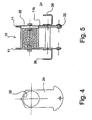
- a length adjusting element 24 In order to reduce the length of the moulding bush, for example to have a smaller stopper, use is made of a length adjusting element 24, practically made up of a sheet having a thickness equivalent to the difference between the maximum bush length available between the plates 11 (in the example of the description, the distance between the plates) and the length of the bush to be used for forming the stopper.
- a sheet is inserted into one of the two tracks 16 and locked at an end using the stop insert (in a longer version with respect to the case when element 24 is not present) associated to that track.
- the sheet has a circular through hole 25, substantially having the same size as the apertures 18 formed in the plates 11. When the sheet 24 is arranged in position, such through hole 15 is coaxial with respect to the apertures 18.
- the end of the sheet 24 opposite to the locking end is counter-shaped to the upper stop abutments 17 of the track 16.
- Respective stirrups 26 are arranged on the outer faces 11 b of the plates 11 for allowing the connection of the mould 10 to drive means for driving the mould throughout the forming apparatus, such means being described hereafter.
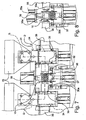
- a system for forming cork stoppers using a plurality of such moulds 10 can be seen in figure 6 and it is indicated at S in its entirety.
- Such system provides for means 30 for driving the moulds 10 throughout various work stations, among which a dosing station D which comprises, facing each other, two devices 31 for dosing granules inside the bushes 15 of the moulds 10.
- the devices 31 are of a type known as such.
- the drive means 30 comprise two chains 30a (denoted with a dash-dot line) mounted parallel on respective motorized pulleys 33 (only one of them is shown in figure 6 ) and corresponding idler means (not shown) which allows the chains to move on two parallel vertical planes.
- each stirrup 26 of a mould 10 is reversibly fixed to a respective chain.
- the moulds 10 are fixed to the chains (for example through bolts screwed onto counter-supports provided for on the same chains) in such a manner that the track 16 takes on a vertical arrangement.
- FIG 6 there is shown a lower branch 30a' of the chain which carries the moulds 10 returning from the stopper extraction zone, to a couple of granule dosing devices 31. From the lower branch 30a' the moulds are rotated by 180° on the pulley, thus positioning them on an upper branch 30a" of the chain which carries them to the dosing station.
- Each granule dosing device 31 comprises a hopper 33 for introducing granules, drawers 34, delineated by a dashed line in figure 7 , wherein the doses are prepared, and nozzles 35 for introducing the doses of granules into the bushes 15 of the moulds 10.
- the path of the granules is marked in figure 7 by a dashed line G.
- each granule dosing device 31 comprises two dosing drawers 34 with corresponding nozzles 35 which simultaneously feed two respective moulds.
- the two dosing devices 31 facing each other work simultaneously and each prepare a half of the dose.
- Means 27 for centering the mould 10 with respect to granule dosing devices for dosing the granules in the bush, are associated to the same mould. Such means are required due to the fact that the center-to-center distance between the moulds along the chain may vary over time (for example due to wear and occurrence of clearances on the chain and in the mechanisms associated thereto, and due to the stretching of the same chain) and it is therefore necessary to ensure a correct positioning of the mould on the dosing station in case of a displacement induced by the chain which might not be sufficiently precise.
- centering means 27 comprise two opposite centering references 28 defined on the lateral edges of the plates 11, such as two concave lateral recesses of the plates which are adapted to be coupled with respective centering pins 35a of respective nozzles 35.
- Figure 7 shows a dosing station wherein a mould 10 is represented during the step of introducing a dose of granules with the bush at the open position to allow for the loading.
- the nozzles 35 which are performing the loading step, are moved towards the bush by means of horizontal translation actuators 36, such as cylinders. It should be observed how the nozzles end up in abutment against respective bases of the bush that project with respect to the diameter of the respective circular apertures 18 formed in the opposite plates 11. In practice, the nozzles 35 have dimensions in the range between the diameter of the circular apertures 18 and the inner diameter of the bush 15.
- the bush 15 is displaced vertically through displacement means.
- a vertical displacement actuator 37 such as a cylinder
- a second vertical displacement actuator 38 At the upper part of the bush, in contact therewith, there is a second vertical displacement actuator 38.
- the second vertical displacement actuator 38 When the bush is filled with granules, the second vertical displacement actuator 38, the upper one, is activated with a consequent pressure exerted on the bush 15 (see figure 8 ).
- the latter lowers, abutting against the vertical displacement actuator 36, which, retracting, still continues to support the bush.
- the bush 15 Upon reaching the closed position, the bush 15 is in abutment against the lower stop means 19.
- the nozzles 35 are moved backwards, freeing the mould, and the chain drive means transport the granule-filled moulds outside the dosing station, driving the subsequent moulds to be filled into the same station.
- the described mould which advantageously has only one moulding bush, can be made up of two opposite plates between which parallel guide means are arranged for guiding two bushes which may displace parallel with respect to each other but on distinct displacement lines.
- the mould may also comprise three bushes that are displaced on parallel lines.
- the interaction of the nozzles of the dosing devices with the loading apertures of the mould according to the invention permits to avoid wasting granules during the loading step, and at the same time the cleanliness of the components is improved.
- the particular structure of the mould allows for a wider adjustment range of the capacity of the moulding bushes with respect to the moulds of the prior art, in that a length adjusting element 24 of the moulding bush can be selected having the desired thickness, and replaced anytime at will.
- the variant embodiment illustrated in figure 9 and figure 10 is capable of attaining a further important advantage.
- the guide tracks 116 and i.e. practically the foils which, welded to the inner faces 111a of the plates 111, define the tracks themselves, have a slightly greater thickness (increased for example to about 3 mm), in such a manner to allow the insertion, still between the plates 111, of small auxiliary plates 124 contoured identically to the above mentioned length adjuster of the bush (shown in figure 4 ).
- auxiliary plates 124 Mounting of such contoured auxiliary plates 124 is carried out in a manner analogous to the length adjuster, by inserting the same auxiliary plates into respective tracks 116, and locking by means of the upper stop means 117 and the stop inserts 122, suitably increased in length.
- the auxiliary small plates 124 in turn have through holes 125 corresponding to the apertures 118 formed in the main plates 111, having a diameter greater with respect to the inner diameter of the bush 115, hence the latter is held tight by the abutment of the two small plates 124 on both sides.
Landscapes
- Engineering & Computer Science (AREA)
- Mechanical Engineering (AREA)
- Life Sciences & Earth Sciences (AREA)
- Forests & Forestry (AREA)
- Dry Formation Of Fiberboard And The Like (AREA)
- Moulds For Moulding Plastics Or The Like (AREA)
Claims (16)
- Un moule pour la fabrication de bouchons en liège aggloméré, comportant au moins un manchon de moulage (15) disposé entre deux plaques opposées (11) séparées par des éléments d'entretoise (12) fixés aux plaques (11), et déplaçable le long d'une direction de déplacement (L) entre une position d'ouverture pour introduire des granulés de liège ou extraire le bouchon formé, et une position d'obturation, un manchon de moulage unique (15) étant disposé le long de ladite direction de déplacement (L), ledit moule étant caractérisé en ce que des moyens de guidage (14) sont agencés sur une face interne (11a) d'au moins l'une des dites plaques (11), pour permettre le glissement du dit manchon de moulage unique(15) de ladite position d'ouverture à ladite position d'obturation, lesdits moyens de guidage (14) comprenant des moyens d'arrêt (19) démontables adaptés pour définir une butée pour le manchon lorsqu'il est dans ladite position d'obturation, et, après avoir été enlevés, permettre l'enlèvement du manchon (15) d'entre les plaques (11) et son insertion entre ces plaques.
- Le moule selon la revendication 1, caractérisé en ce que lesdits moyens de guidage (14) comportent une piste (16) ouverte à l'extrémité correspondant à la position d'obturation du manchon.
- Le moule selon l'une des revendications 1 et 2, caractérisé en ce que lesdits moyens d'arrêt (19) démontables comportent un siège (20), formé dans la face interne (11a) d'une plaque correspondante (11), pour adapter un insert d'arrêt (22) s'étendant transversalement par rapport à la direction de glissement du manchon (15), des moyens de blocage réversibles (23) étant associés au dit insert d'arrêt (22) pour bloquer celui-ci dans ledit siège (20).
- Le moule selon l'une des revendications 2 et 3, caractérisé en ce que ladite piste (16) comprend deux rails parallèles (16a) définis sur les bords latéraux des plaques (11), espacés l'un de l'autre d'une distance sensiblement équivalente au diamètre extérieur du manchon (15), lesdits rails étant reliés à la partie supérieure de la piste (16) pour définir des butées d'arrêt supérieures (17) pour le manchon (15).
- Le moule selon l'une quelconque des revendications précédentes, caractérisé en ce qu'il comporte un élément démontable (24) d'ajustement de longueur pour modifier la longueur du dit au moins un manchon amovible (15), adapté pour être agencé contre la face interne (11a) d'une des dites plaques (11), une base du dit manchon butant contre ledit élément d'ajustement de longueur (24) qui présente un orifice traversant (25) ayant une dimension sensiblement équivalente à des ouvertures (18) pratiquées dans lesdites plaques (11), ledit orifice traversant (25) étant adapté pour devenir coaxial avec lesdites ouvertures (18) lorsque l'élément d'ajustement de longueur est couplé à la plaque correspondante (11).
- Le moule selon la revendication 5, caractérisé en ce que ledit élément d'ajustement de longueur (24) est constitué d'une feuille ayant une épaisseur équivalente à la différence entre la longueur maximale du manchon disponible entre lesdites plaques (11) et la longueur du manchon prévu pour être utilisé pour réaliser le bouchon, ladite feuille étant adaptée pour être insérée dans une des dites pistes (16) et bloquée à une extrémité avec un insert d'arrêt correspondant (22).
- Le moule selon l'une quelconque des revendications 1 à 4, caractérisé en ce qu'il comporte des plaques auxiliaires laminées (124) adaptées pour être insérées de façon démontable dans lesdits moyens de guidage pour réaliser une butée pour les extrémités respectives du dit manchon, lesdites plaques laminées (124) comprenant des orifices traversants (125) qui correspondent à des ouvertures (118) formées dans lesdites plaques (111), et ayant un diamètre plus grand que le diamètre intérieur du dit manchon (115).
- Le moule selon la revendication 7, caractérisé en ce que lesdites plaques (124) sont bloquées à une extrémité par un insert d'arrêt correspondant (122).
- Le moule selon l'une des revendications 7 et 8, où lesdites pistes de guidage (116) ont une plus grande largeur de façon qu'elles permettent l'insertion des dites plaques.
- Le moule selon l'une quelconque des revendications précédentes, caractérisé en ce qu'un manchon de moulage unique (15) est compris entre lesdites plaques (11).
- Un procédé pour fabriquer des bouchons en liège aggloméré avec une pluralité de moules (10) munis de manchons de moulage de liège (15), lesdits moules étant commandés via des postes de travail (D) qui comportent au moins un dispositif de dosage (31) pour doser des granulés de liège dans les manchons (15) des moules (10), les manchons (15) étant déplacées le long d'une direction de déplacement (L) entre une position d'ouverture de manchon, pour le chargement des granulés et l'extraction du bouchon formé, et une position d'obturation de manchon, un manchon de moulage unique (15) étant agencé le long de ladite direction de déplacement (L), caractérisé en ce que ledit manchon de moulage unique (15) glisse le long de moyens de guidage (14) agencés sur une face interne (11a) d'au moins l'une des dites plaques (11), de ladite position d'ouverture à ladite position d'obturation, le manchon butant sur des moyens d'arrêt (19) des dits moyens de guidage (14) lorsqu'il est dans sa position d'obturation, lesdits moyens d'arrêt étant enlevés pour permettre l'enlèvement du manchon (15) d'entre les plaques (11) et son insertion entre ces plaques.
- Le procédé pour fabriquer des bouchons en liège selon la revendication 11, caractérisé en ce que les manchons (15) des dits moules (10) sont déplacés verticalement.
- Le procédé pour fabriquer des bouchons en liège selon l'une des revendications 11 et 12, caractérisé en ce qu'une buse d'injection (35) d'au moins un dispositif de dosage (31) est en liaison directe avec l'intérieur du dit manchon de moulage (15) du moule (10) pendant l'étape de chargement des granulés.
- Le procédé pour fabriquer des bouchons en liège selon la revendication 13, caractérisé en ce que ladite buse (35) vient buter contre la base du dit manchon (15).
- Le procédé pour fabriquer des bouchons en liège selon l'une des revendications 12 à 14, caractérisé en ce que chaque moule (10) est centré par rapport au dit au moins un dispositif de dosage (31).
- Le procédé pour fabriquer des bouchons en liège selon la revendication 15, caractérisé en ce que deux références de centrage opposées (28) de moyens de centrage (27) définis sur les bords latéraux des dites plaques (11), sont couplées à des ergots de centrage respectifs (35a) des buses respectives (35).
Applications Claiming Priority (2)
| Application Number | Priority Date | Filing Date | Title |
|---|---|---|---|
| ITFI2008A000202A IT1391079B1 (it) | 2008-10-20 | 2008-10-20 | Stampo per la realizzazione di tappi in agglomerato di sughero |
| ITFI20080058 ITFI20080058U1 (it) | 2008-12-10 | 2008-12-10 | Stampo per la realizzazione di tappi in agglomerato di sughero |
Publications (2)
| Publication Number | Publication Date |
|---|---|
| EP2177331A1 EP2177331A1 (fr) | 2010-04-21 |
| EP2177331B1 true EP2177331B1 (fr) | 2013-01-30 |
Family
ID=41624845
Family Applications (1)
| Application Number | Title | Priority Date | Filing Date |
|---|---|---|---|
| EP20090173484 Active EP2177331B1 (fr) | 2008-10-20 | 2009-10-20 | Moule pour la fabrication de bouchons en liège aggloméré |
Country Status (3)
| Country | Link |
|---|---|
| EP (1) | EP2177331B1 (fr) |
| ES (1) | ES2403216T3 (fr) |
| PT (1) | PT2177331E (fr) |
Families Citing this family (1)
| Publication number | Priority date | Publication date | Assignee | Title |
|---|---|---|---|---|
| ITUA20162476A1 (it) * | 2016-04-11 | 2017-10-11 | Meacci S R L | Apparecchiatura di stampaggio per la realizzazione di tappi in agglomerato di sughero |
Family Cites Families (6)
| Publication number | Priority date | Publication date | Assignee | Title |
|---|---|---|---|---|
| GB177474A (en) * | 1922-01-05 | 1922-03-30 | Charles Edward Mcmanus | Improvements in carriers for cork rod bakers |
| US1627601A (en) * | 1922-08-18 | 1927-05-10 | Crown Cork And Seal Company Of | Apparatus for compacting granular material |
| US1673904A (en) * | 1925-07-01 | 1928-06-19 | Crown Cork & Seal Co | Apparatus for producing articles of compacted granular material |
| US2477258A (en) * | 1944-07-01 | 1949-07-26 | Hpm Dev Corp | Turret injection machine |
| US2830326A (en) * | 1953-06-08 | 1958-04-15 | Weisenburg Andrew | Art of extruding cork for the manufacture of bottle caps and the like |
| IT1218538B (it) * | 1987-03-19 | 1990-04-19 | Meacci Srl | Apparecchiatura per la produzione automatica di tappi di sughero agglomerato |
-
2009
- 2009-10-20 PT PT09173484T patent/PT2177331E/pt unknown
- 2009-10-20 ES ES09173484T patent/ES2403216T3/es active Active
- 2009-10-20 EP EP20090173484 patent/EP2177331B1/fr active Active
Also Published As
| Publication number | Publication date |
|---|---|
| ES2403216T3 (es) | 2013-05-16 |
| EP2177331A1 (fr) | 2010-04-21 |
| PT2177331E (pt) | 2013-05-06 |
Similar Documents
| Publication | Publication Date | Title |
|---|---|---|
| US4462783A (en) | Mechanism for exchanging molding dies in an injection molding machine | |
| EP2845813B1 (fr) | Unité de serrage pour récipients sur des machines de traitement de récipients | |
| DE112010004993B4 (de) | Reifenvulkanisiervorrichtung | |
| US4767302A (en) | Exchangeable multiplunger transfer molding die apparatus | |
| DE102014207591B4 (de) | Multishot Spritzgussvorrichtung | |
| EP2177331A1 (fr) | Moule pour la fabrication de bouchons en liège aggloméré | |
| EP0397674A1 (fr) | Procede et installation pour fabriquer des pieces moulees en matiere plastique. | |
| EP0190276B1 (fr) | Appareil de moulage | |
| AT506018A2 (de) | Vorrichtung zur herstellung von spritzgussteilen | |
| WO2015024657A1 (fr) | Machine de moulage par injection à plusieurs composants pourvue d'une partie centrale rotative | |
| CN102015238B (zh) | 用于保持模具的方法和装置 | |
| GB2124541A (en) | Mechanism for exchanging molding dies in an injection molding machine | |
| US9475228B2 (en) | Adjustable platen assembly for use in a clamp station | |
| WO2008064456A1 (fr) | Appareil d'alignement de position de barre de coulée externe | |
| EP2691229B1 (fr) | Outil pour le moulage par injection d'objets | |
| DE69205055T2 (de) | Verfahren und Vorrichtung zum Anbringen von Etiketten in einer Form. | |
| DE102015008560B4 (de) | Vertikale Spritzgießmaschine oder Spritzpresse | |
| DE2838079A1 (de) | Station zum fuellen von geschlossenen formen mit schaeumbarem kunststoffmaterial | |
| DE102010047812A1 (de) | Verfahren zum nachträglichen Über- und/oder Anspritzen von Fertig- oder Halbfertigprodukten | |
| DE1529866C3 (de) | Vorrichtung zum Formen und Vulkanisieren von Gummigegenständen bzw. Härten von Kunststoffgegenständea | |
| DE819132C (de) | Vorrichtung zum Herstellen von Spritzguss | |
| KR20200134760A (ko) | 유·공압 기밀유지용 디링 제조방법 및 그 장치 | |
| KR101042607B1 (ko) | 상부 몰드의 연속 공급구조를 갖는 스탬핑 장치 | |
| US5984660A (en) | Apparatus for processing plastic sheet | |
| ITFI20080058U1 (it) | Stampo per la realizzazione di tappi in agglomerato di sughero |
Legal Events
| Date | Code | Title | Description |
|---|---|---|---|
| PUAI | Public reference made under article 153(3) epc to a published international application that has entered the european phase |
Free format text: ORIGINAL CODE: 0009012 |
|
| AK | Designated contracting states |
Kind code of ref document: A1 Designated state(s): AT BE BG CH CY CZ DE DK EE ES FI FR GB GR HR HU IE IS IT LI LT LU LV MC MK MT NL NO PL PT RO SE SI SK SM TR |
|
| 17P | Request for examination filed |
Effective date: 20100908 |
|
| 17Q | First examination report despatched |
Effective date: 20101118 |
|
| GRAP | Despatch of communication of intention to grant a patent |
Free format text: ORIGINAL CODE: EPIDOSNIGR1 |
|
| RIC1 | Information provided on ipc code assigned before grant |
Ipc: B27J 5/00 20060101AFI20120426BHEP |
|
| GRAS | Grant fee paid |
Free format text: ORIGINAL CODE: EPIDOSNIGR3 |
|
| GRAP | Despatch of communication of intention to grant a patent |
Free format text: ORIGINAL CODE: EPIDOSNIGR1 |
|
| GRAA | (expected) grant |
Free format text: ORIGINAL CODE: 0009210 |
|
| AK | Designated contracting states |
Kind code of ref document: B1 Designated state(s): AT BE BG CH CY CZ DE DK EE ES FI FR GB GR HR HU IE IS IT LI LT LU LV MC MK MT NL NO PL PT RO SE SI SK SM TR |
|
| REG | Reference to a national code |
Ref country code: GB Ref legal event code: FG4D |
|
| REG | Reference to a national code |
Ref country code: CH Ref legal event code: EP |
|
| REG | Reference to a national code |
Ref country code: AT Ref legal event code: REF Ref document number: 595629 Country of ref document: AT Kind code of ref document: T Effective date: 20130215 Ref country code: CH Ref legal event code: EP |
|
| REG | Reference to a national code |
Ref country code: IE Ref legal event code: FG4D |
|
| REG | Reference to a national code |
Ref country code: DE Ref legal event code: R096 Ref document number: 602009013122 Country of ref document: DE Effective date: 20130321 |
|
| REG | Reference to a national code |
Ref country code: PT Ref legal event code: SC4A Free format text: AVAILABILITY OF NATIONAL TRANSLATION Effective date: 20130426 |
|
| REG | Reference to a national code |
Ref country code: ES Ref legal event code: FG2A Ref document number: 2403216 Country of ref document: ES Kind code of ref document: T3 Effective date: 20130516 |
|
| REG | Reference to a national code |
Ref country code: AT Ref legal event code: MK05 Ref document number: 595629 Country of ref document: AT Kind code of ref document: T Effective date: 20130130 |
|
| REG | Reference to a national code |
Ref country code: LT Ref legal event code: MG4D |
|
| REG | Reference to a national code |
Ref country code: NL Ref legal event code: VDEP Effective date: 20130130 |
|
| PG25 | Lapsed in a contracting state [announced via postgrant information from national office to epo] |
Ref country code: SE Free format text: LAPSE BECAUSE OF FAILURE TO SUBMIT A TRANSLATION OF THE DESCRIPTION OR TO PAY THE FEE WITHIN THE PRESCRIBED TIME-LIMIT Effective date: 20130130 Ref country code: NO Free format text: LAPSE BECAUSE OF FAILURE TO SUBMIT A TRANSLATION OF THE DESCRIPTION OR TO PAY THE FEE WITHIN THE PRESCRIBED TIME-LIMIT Effective date: 20130430 Ref country code: IS Free format text: LAPSE BECAUSE OF FAILURE TO SUBMIT A TRANSLATION OF THE DESCRIPTION OR TO PAY THE FEE WITHIN THE PRESCRIBED TIME-LIMIT Effective date: 20130530 Ref country code: BG Free format text: LAPSE BECAUSE OF FAILURE TO SUBMIT A TRANSLATION OF THE DESCRIPTION OR TO PAY THE FEE WITHIN THE PRESCRIBED TIME-LIMIT Effective date: 20130430 Ref country code: BE Free format text: LAPSE BECAUSE OF FAILURE TO SUBMIT A TRANSLATION OF THE DESCRIPTION OR TO PAY THE FEE WITHIN THE PRESCRIBED TIME-LIMIT Effective date: 20130130 Ref country code: LT Free format text: LAPSE BECAUSE OF FAILURE TO SUBMIT A TRANSLATION OF THE DESCRIPTION OR TO PAY THE FEE WITHIN THE PRESCRIBED TIME-LIMIT Effective date: 20130130 Ref country code: AT Free format text: LAPSE BECAUSE OF FAILURE TO SUBMIT A TRANSLATION OF THE DESCRIPTION OR TO PAY THE FEE WITHIN THE PRESCRIBED TIME-LIMIT Effective date: 20130130 |
|
| PG25 | Lapsed in a contracting state [announced via postgrant information from national office to epo] |
Ref country code: NL Free format text: LAPSE BECAUSE OF FAILURE TO SUBMIT A TRANSLATION OF THE DESCRIPTION OR TO PAY THE FEE WITHIN THE PRESCRIBED TIME-LIMIT Effective date: 20130130 Ref country code: FI Free format text: LAPSE BECAUSE OF FAILURE TO SUBMIT A TRANSLATION OF THE DESCRIPTION OR TO PAY THE FEE WITHIN THE PRESCRIBED TIME-LIMIT Effective date: 20130130 Ref country code: PL Free format text: LAPSE BECAUSE OF FAILURE TO SUBMIT A TRANSLATION OF THE DESCRIPTION OR TO PAY THE FEE WITHIN THE PRESCRIBED TIME-LIMIT Effective date: 20130130 Ref country code: SI Free format text: LAPSE BECAUSE OF FAILURE TO SUBMIT A TRANSLATION OF THE DESCRIPTION OR TO PAY THE FEE WITHIN THE PRESCRIBED TIME-LIMIT Effective date: 20130130 Ref country code: GR Free format text: LAPSE BECAUSE OF FAILURE TO SUBMIT A TRANSLATION OF THE DESCRIPTION OR TO PAY THE FEE WITHIN THE PRESCRIBED TIME-LIMIT Effective date: 20130501 Ref country code: LV Free format text: LAPSE BECAUSE OF FAILURE TO SUBMIT A TRANSLATION OF THE DESCRIPTION OR TO PAY THE FEE WITHIN THE PRESCRIBED TIME-LIMIT Effective date: 20130130 |
|
| PG25 | Lapsed in a contracting state [announced via postgrant information from national office to epo] |
Ref country code: HR Free format text: LAPSE BECAUSE OF FAILURE TO SUBMIT A TRANSLATION OF THE DESCRIPTION OR TO PAY THE FEE WITHIN THE PRESCRIBED TIME-LIMIT Effective date: 20130130 |
|
| PG25 | Lapsed in a contracting state [announced via postgrant information from national office to epo] |
Ref country code: DK Free format text: LAPSE BECAUSE OF FAILURE TO SUBMIT A TRANSLATION OF THE DESCRIPTION OR TO PAY THE FEE WITHIN THE PRESCRIBED TIME-LIMIT Effective date: 20130130 Ref country code: CZ Free format text: LAPSE BECAUSE OF FAILURE TO SUBMIT A TRANSLATION OF THE DESCRIPTION OR TO PAY THE FEE WITHIN THE PRESCRIBED TIME-LIMIT Effective date: 20130130 Ref country code: EE Free format text: LAPSE BECAUSE OF FAILURE TO SUBMIT A TRANSLATION OF THE DESCRIPTION OR TO PAY THE FEE WITHIN THE PRESCRIBED TIME-LIMIT Effective date: 20130130 Ref country code: RO Free format text: LAPSE BECAUSE OF FAILURE TO SUBMIT A TRANSLATION OF THE DESCRIPTION OR TO PAY THE FEE WITHIN THE PRESCRIBED TIME-LIMIT Effective date: 20130130 Ref country code: SK Free format text: LAPSE BECAUSE OF FAILURE TO SUBMIT A TRANSLATION OF THE DESCRIPTION OR TO PAY THE FEE WITHIN THE PRESCRIBED TIME-LIMIT Effective date: 20130130 |
|
| PG25 | Lapsed in a contracting state [announced via postgrant information from national office to epo] |
Ref country code: CY Free format text: LAPSE BECAUSE OF FAILURE TO SUBMIT A TRANSLATION OF THE DESCRIPTION OR TO PAY THE FEE WITHIN THE PRESCRIBED TIME-LIMIT Effective date: 20130130 |
|
| PLBE | No opposition filed within time limit |
Free format text: ORIGINAL CODE: 0009261 |
|
| STAA | Information on the status of an ep patent application or granted ep patent |
Free format text: STATUS: NO OPPOSITION FILED WITHIN TIME LIMIT |
|
| 26N | No opposition filed |
Effective date: 20131031 |
|
| PGFP | Annual fee paid to national office [announced via postgrant information from national office to epo] |
Ref country code: DE Payment date: 20131021 Year of fee payment: 5 |
|
| REG | Reference to a national code |
Ref country code: DE Ref legal event code: R097 Ref document number: 602009013122 Country of ref document: DE Effective date: 20131031 |
|
| PG25 | Lapsed in a contracting state [announced via postgrant information from national office to epo] |
Ref country code: MC Free format text: LAPSE BECAUSE OF FAILURE TO SUBMIT A TRANSLATION OF THE DESCRIPTION OR TO PAY THE FEE WITHIN THE PRESCRIBED TIME-LIMIT Effective date: 20130130 |
|
| REG | Reference to a national code |
Ref country code: CH Ref legal event code: PL |
|
| GBPC | Gb: european patent ceased through non-payment of renewal fee |
Effective date: 20131020 |
|
| REG | Reference to a national code |
Ref country code: IE Ref legal event code: MM4A |
|
| PG25 | Lapsed in a contracting state [announced via postgrant information from national office to epo] |
Ref country code: GB Free format text: LAPSE BECAUSE OF NON-PAYMENT OF DUE FEES Effective date: 20131020 Ref country code: LI Free format text: LAPSE BECAUSE OF NON-PAYMENT OF DUE FEES Effective date: 20131031 Ref country code: CH Free format text: LAPSE BECAUSE OF NON-PAYMENT OF DUE FEES Effective date: 20131031 |
|
| PG25 | Lapsed in a contracting state [announced via postgrant information from national office to epo] |
Ref country code: IE Free format text: LAPSE BECAUSE OF NON-PAYMENT OF DUE FEES Effective date: 20131020 |
|
| REG | Reference to a national code |
Ref country code: DE Ref legal event code: R119 Ref document number: 602009013122 Country of ref document: DE |
|
| PG25 | Lapsed in a contracting state [announced via postgrant information from national office to epo] |
Ref country code: SM Free format text: LAPSE BECAUSE OF FAILURE TO SUBMIT A TRANSLATION OF THE DESCRIPTION OR TO PAY THE FEE WITHIN THE PRESCRIBED TIME-LIMIT Effective date: 20130130 |
|
| PG25 | Lapsed in a contracting state [announced via postgrant information from national office to epo] |
Ref country code: TR Free format text: LAPSE BECAUSE OF FAILURE TO SUBMIT A TRANSLATION OF THE DESCRIPTION OR TO PAY THE FEE WITHIN THE PRESCRIBED TIME-LIMIT Effective date: 20130130 |
|
| PG25 | Lapsed in a contracting state [announced via postgrant information from national office to epo] |
Ref country code: HU Free format text: LAPSE BECAUSE OF FAILURE TO SUBMIT A TRANSLATION OF THE DESCRIPTION OR TO PAY THE FEE WITHIN THE PRESCRIBED TIME-LIMIT; INVALID AB INITIO Effective date: 20091020 Ref country code: LU Free format text: LAPSE BECAUSE OF NON-PAYMENT OF DUE FEES Effective date: 20131020 Ref country code: DE Free format text: LAPSE BECAUSE OF NON-PAYMENT OF DUE FEES Effective date: 20150501 Ref country code: MK Free format text: LAPSE BECAUSE OF FAILURE TO SUBMIT A TRANSLATION OF THE DESCRIPTION OR TO PAY THE FEE WITHIN THE PRESCRIBED TIME-LIMIT Effective date: 20130130 |
|
| PG25 | Lapsed in a contracting state [announced via postgrant information from national office to epo] |
Ref country code: MT Free format text: LAPSE BECAUSE OF FAILURE TO SUBMIT A TRANSLATION OF THE DESCRIPTION OR TO PAY THE FEE WITHIN THE PRESCRIBED TIME-LIMIT Effective date: 20130130 |
|
| REG | Reference to a national code |
Ref country code: FR Ref legal event code: PLFP Year of fee payment: 7 |
|
| REG | Reference to a national code |
Ref country code: FR Ref legal event code: PLFP Year of fee payment: 8 |
|
| REG | Reference to a national code |
Ref country code: FR Ref legal event code: PLFP Year of fee payment: 9 |
|
| REG | Reference to a national code |
Ref country code: FR Ref legal event code: PLFP Year of fee payment: 10 |
|
| PGFP | Annual fee paid to national office [announced via postgrant information from national office to epo] |
Ref country code: GB Payment date: 20181219 Year of fee payment: 11 |
|
| PG25 | Lapsed in a contracting state [announced via postgrant information from national office to epo] |
Ref country code: FR Free format text: LAPSE BECAUSE OF NON-PAYMENT OF DUE FEES Effective date: 20191031 |
|
| PGFP | Annual fee paid to national office [announced via postgrant information from national office to epo] |
Ref country code: PT Payment date: 20241010 Year of fee payment: 16 |
|
| PGFP | Annual fee paid to national office [announced via postgrant information from national office to epo] |
Ref country code: ES Payment date: 20241127 Year of fee payment: 16 Ref country code: IT Payment date: 20241008 Year of fee payment: 16 |