EP2177320A1 - Irreversible-type toggle-lever drive device - Google Patents
Irreversible-type toggle-lever drive device Download PDFInfo
- Publication number
- EP2177320A1 EP2177320A1 EP08018026A EP08018026A EP2177320A1 EP 2177320 A1 EP2177320 A1 EP 2177320A1 EP 08018026 A EP08018026 A EP 08018026A EP 08018026 A EP08018026 A EP 08018026A EP 2177320 A1 EP2177320 A1 EP 2177320A1
- Authority
- EP
- European Patent Office
- Prior art keywords
- toggle
- work arm
- guide surface
- drive device
- crank
- Prior art date
- Legal status (The legal status is an assumption and is not a legal conclusion. Google has not performed a legal analysis and makes no representation as to the accuracy of the status listed.)
- Withdrawn
Links
Images


Classifications
-
- B—PERFORMING OPERATIONS; TRANSPORTING
- B25—HAND TOOLS; PORTABLE POWER-DRIVEN TOOLS; MANIPULATORS
- B25B—TOOLS OR BENCH DEVICES NOT OTHERWISE PROVIDED FOR, FOR FASTENING, CONNECTING, DISENGAGING OR HOLDING
- B25B5/00—Clamps
- B25B5/06—Arrangements for positively actuating jaws
- B25B5/12—Arrangements for positively actuating jaws using toggle links
- B25B5/122—Arrangements for positively actuating jaws using toggle links with fluid drive
Definitions
- the present invention concerns a toggle-lever drive device having a rocking work arm, for example in the form of a clamping device for clamping work pieces or a laser welding device for work pieces of sheet metal or a stamping press device for imprinting reference numbers on sheet metal.
- toggle-lever drive devices which comprise a rocking work arm, operatively connected to a linear actuator by means of a toggle-lever mechanism.
- the drive devices of this type which can be configured for various uses, for example as clamping devices for clamping work pieces or spot welding devices for work pieces of sheet metal, are commonly used in the car manufacturing field for assembling the bodywork of motor vehicles and the like.
- EP-A-0 836 912 describes a toggle-lever clamping device for clamping work pieces, comprising a clamping arm supported by a rotatable drive shaft, operatively connected to a linear actuator by means of a toggle-lever mechanism; the linear actuator has a linearly movable thrust member provided with coaxial sliding rollers movable along respective guide surfaces having an arched profile in correspondence with a forward position of the thrust member.
- the toggle-lever mechanism in turn comprises a crank and a connecting link articulated to one another, in which the crank is connected to the drive shaft to rotate together with the clamping arm, while the connecting link is connected to the thrust member in correspondence with the sliding rollers.
- the arched profile of the guide surfaces for guiding the rollers is shaped in such a way that the angle ⁇ , formed between the longitudinal axis of the connecting link of the toggle-lever mechanism and the axis orthogonal to the tangent at the contact point between the guide surface and each sliding roller, is substantially constant along the entire arched profile of the same guide surface; in particular, the known devices are conformed in such a way that the angle ⁇ is usually comprised between 10° and 12°.
- the object of the present invention is to provide a toggle-lever drive device having a rocking work arm, whereby it is possible to exert with the work arm an operative force having an effectively constant value for any possible working position of the arm itself, and which at the same time allows the work arm to irreversibly maintain the working position assumed, in the absence of actuating force by the linear actuator, or in the event of high forces tending to move the arm towards the non-operative position.
- a toggle-lever drive device having a rocking work arm, of the type comprising a pivotally supported work arm, operatively connected to a linear actuator by a toggle-lever mechanism, to rotate between a non-operative position and a working position comprised within a range of angular values,
- Fig. 1 shows a toggle-lever drive device having a rocking work arm, according to the present invention, which is in particular in the form of a clamping device for clamping work pieces, in which an external stop for retaining the work arm is provided; it cannot be excluded however that the drive device may be configured for other uses, for example in the form of a laser welding device, in which the work arm is shaped and disposed for welding work pieces of sheet metal, in which an internal stop for the crank of the toggle and/or an adjustable upper stop are provided, or in the form of a stamping press device for imprinting reference numbers on sheet metal.
- the device of Fig. 1 comprises a box-shaped support body 10 for supporting a rocking work arm 11, conformed to clamp work pieces against a shoulder surface forming part of the device itself or provided on a separate structure.
- the work arm 11 is supported by a rotatable drive shaft 13, which is operatively connected to a linear actuator 14 by means of a toggle-lever mechanism 15, in such a way as to drive the arm 11 to rotate between a non-operative position and a working position comprised within a range of angular values, in relation to the operative requirements.
- the working position of the work arm 11 can be precisely set thanks to a stop member or to an adjustable external stop mechanism, for example comprising a first pin 24, adjustably connected to the work arm 11 by means of a screw thread 24', and a second fixed pin 25 supported by a side protrusion 12 of the body 10 of the device, the aforesaid pins 24, 25 being shaped and disposed in such a way as to come into contact with each other in correspondence with the working position of the arm 11 itself, causing it to stop.
- a stop member or to an adjustable external stop mechanism for example comprising a first pin 24, adjustably connected to the work arm 11 by means of a screw thread 24', and a second fixed pin 25 supported by a side protrusion 12 of the body 10 of the device, the aforesaid pins 24, 25 being shaped and disposed in such a way as to come into contact with each other in correspondence with the working position of the arm 11 itself, causing it to stop.
- the linear actuator 14 for example in the form of a pneumatic cylinder, is provided with a linearly movable thrust member 16 to exert an actuating force F, between a backward position and a forward position, in which the clamping arm 11 is in the working position.
- the thrust member 16, at the end facing towards the toggle-lever mechanism 15, is provided with at least one sliding roller 17, having a radius R, pivotally supported on a rotational pin 18.
- the sliding roller 17 is movable along at least one guide surface 19 provided inside the box-shaped body 10, which has an arched profile 19' in correspondence with the forward position of the thrust member 16; preferentially the arched profile 19' is made on a guide cam 20 removably secured within the box-shaped body 10, in such a way as to allow a replacement of the same cam, for example for operative requirements or in the event of wear.
- the toggle-lever mechanism 15 in turn comprises a crank 21 of a length A, connected to the drive shaft 13 to rotate with the clamping arm 11, and a connecting link 22 of a length B, connected to the thrust member 16 in correspondence with the rotational pin 18 of the sliding roller 17; the crank 21 and the connecting link 22 are also connected to each other by means of a hinge pin 23, and form between each other an angle ⁇ , as indicated in Fig. 3 .
- the above toggle-lever mechanism 15 is of a per se known type, and has a dead centre condition, in which the crank 21 and the connecting link 22 are substantially at right angles with each other, with the thrust member 16 in the forward position; in correspondence with this condition, the clamping arm 11 assumes its working position, exerting high operative forces.
- the connecting link 22 of the toggle-lever mechanism 15 can be of the rigid type, as illustrated in Fig. 1 , or can advantageously be of a type elastically yielding in the axial direction in a controlled manner, the type being chosen in relation to the operative requirements of the device.
- the arched profile 19' of the guide surface 19 exerts on the roller 17 a reaction force Q" orthogonally directed to the tangent at the contact point between the roller and the arched profile itself, and oriented according to an angle ⁇ with respect to the longitudinal axis of the connecting link 22.
- force of a constant value is understood to mean that the force is maintained at a nearly constant value, except for a deviation of a negligible entity with respect to the value of the force itself, for any possible working position of the clamping arm 11 itself.
- the working position of the clamping arm 11 proves to be irreversible in the absence of actuating force by the linear actuator 14, and/or in the presence of high external forces tending to shift the arm 11 itself towards the non-operative position.
- a reference system of Cartesian axes X and Y is defined, in which the drive shaft 13 identifies its origin O, in which the axis Y is directed in the same way as the crank 21 when the latter is in a vertical position, or substantially so, in correspondence with the working position of the clamping arm 11, and in which the axis X is directed at right angles to the axis Y, towards the guide surface 19.
- the crank 21 has a length A ranging from 18 mm to 22 mm
- the connecting link 22 has a length B ranging from 18.5 mm to 22.5 mm
- the roller 17 has a radius R ranging from 7 mm to 9 mm.
- the toggle-lever drive device can be configured in the form of a laser welding device for welding superimposed metal sheets; in this case, in place of the external stop mechanism for stopping the work arm 11, an internal stop for the crank of the toggle-lever mechanism and/or an adjustable upper stop for the thrust member are provided.
- the laser welding device comprises a stop element 26 for stopping the thrust member 16, which defines the forward position of the thrust member 16 itself; preferentially, the stop element 26 extends into the body 10 through a hole disposed at the end of the same body 10 opposite to the linear actuator, and can be screwably adjusted in the direction of the axis of the thrust member 16.
- an internal stop 27 for the crank 21 of the toggle-lever mechanism 15 can be provided.
- the internal stop 27, which is interposed between an internal wall of the body 10 and the crank 21 itself, comprises a movable plate 28, elastically supported by Belleville washers 29, which is pressed by the crank 21 until it is brought to rest against a stop surface disposed to the rear of the plate 28 itself, thereby causing the work arm 11 to stop in correspondence with the pre-established working position, and allowing to take up every final slack of the linkage of the device.
- the profile of the guide surface 19 for guiding the sliding roller 17, preferentially has an arched profile 19' which extends into a straight section 19" in correspondence with the most forward position for the thrust member 16.
- the aforesaid straight section 19'' which extends parallel to the axis of the thrust member 16, enables the work arm 11 to assume an intermediate angular position between an open non-operative position and a closed working position.
- the toggle-lever drive device can also be configured in the form of a stamping press device for marking reference numbers or other references on sheet metal.
- the rocking work arm 11 of the drive device supports a marking or stamping tool 30 which cooperates with a side shoulder 31 of the device, or with a separated anvil, to mark a sheet metal disposed therebetween.
- the marking tool 30 comprises a rotatably supported marking drum 32 which can be rotated by a side lever 33 in order to automatically change the reference number of the tool 30 at each rocking movement of the work arm 11.
- the side lever 33 is actuated at the non-operative position of the work arm 11 by a protruding stem 34 connected to the body 10 of the device, thereby rotating the drum 32 or a part thereof.
- the work arm 11 of the device according to the invention exerts a constant operative force for any possible working position of the arm 11, a same marking pressure value is applied on the sheet metal by the marking tool 30, also in the case of different thicknesses of the sheet metal, avoiding any undesired or uncontrolled deformation of the sheet metal.
- connecting link 22 of the type elastically yielding in axial direction in a controlled mode allows to equalize in a better way the mechanical stresses within the toggle-lever mechanism and consequently the operative force for the work arm 11; furthermore, such a connecting link 22 reduces the effort necessary for moving the work arm 11 from the working position to the non-operative position, avoiding any blocking of the work arm 11 in the working position.
- a toggle-lever drive device configured according to the present invention, allows the work arm to exert an operative force of an effectively constant value for any possible working position of the arm itself; moreover, the working position assumed by the work arm is irreversibly maintained, in the absence of actuating force by the linear actuator, or in the event of high forces tending to move the arm towards the non-operative position.
Abstract
The toggle-lever drive device comprises a pivotally supported work arm (11), operatively connected to a linear actuator (14) by a toggle-lever mechanism (15); the linear actuator (14) has a linearly movable thrust member (16), provided with at least one roller (17) sliding along at least one guide surface (19) having an arched profile (19') in correspondence with a forward position of the thrust member (16), in which the arched surface (19') exerts on the roller (17) a reaction force oriented according to an angle a with respect to the connecting link (22). The arched profile (19') of the guide surface (19), the sliding roller (17), the connecting link (22) and the crank (21) of the toggle-lever mechanism (15) are shaped and disposed in such a way as to define values of the angle a equivalent to or lower than 3°, determining for the work arm an operative force of a constant value along the entire arched profile (19') of the guide surface (19).
Description
- The present invention concerns a toggle-lever drive device having a rocking work arm, for example in the form of a clamping device for clamping work pieces or a laser welding device for work pieces of sheet metal or a stamping press device for imprinting reference numbers on sheet metal.
- In general, toggle-lever drive devices are known, which comprise a rocking work arm, operatively connected to a linear actuator by means of a toggle-lever mechanism.
- The drive devices of this type, which can be configured for various uses, for example as clamping devices for clamping work pieces or spot welding devices for work pieces of sheet metal, are commonly used in the car manufacturing field for assembling the bodywork of motor vehicles and the like.
- Within the aforementioned field of use, there is often the need to dispose drive devices having a work arm capable of rotating between a non-operative or rest position and a working position comprised within a range of angular values, and allowing to exert an operative force of a substantially constant value for any working position included within the aforesaid range of angular values.
- For this purpose, a general solution idea to the aforementioned problem has been variously proposed, such as for example in
EP-A-0 836 912 , which substantially consists in providing suitable guide means for guiding the toggle-lever mechanism of the device. - In particular,
EP-A-0 836 912 describes a toggle-lever clamping device for clamping work pieces, comprising a clamping arm supported by a rotatable drive shaft, operatively connected to a linear actuator by means of a toggle-lever mechanism; the linear actuator has a linearly movable thrust member provided with coaxial sliding rollers movable along respective guide surfaces having an arched profile in correspondence with a forward position of the thrust member. - The toggle-lever mechanism in turn comprises a crank and a connecting link articulated to one another, in which the crank is connected to the drive shaft to rotate together with the clamping arm, while the connecting link is connected to the thrust member in correspondence with the sliding rollers.
- In order to attempt to obtain a substantially constant gripping force for the clamping arm, the arched profile of the guide surfaces for guiding the rollers is shaped in such a way that the angle σ, formed between the longitudinal axis of the connecting link of the toggle-lever mechanism and the axis orthogonal to the tangent at the contact point between the guide surface and each sliding roller, is substantially constant along the entire arched profile of the same guide surface; in particular, the known devices are conformed in such a way that the angle σ is usually comprised between 10° and 12°.
- With a solution of this kind, however, it is not possible to effectively obtain a constant clamping force, but there are substantial variations in the force itself in relation to the working position assumed by the clamping arm within the range of possible angular values for the latter; consequently, in certain cases and for certain applications, the clamping force may prove to be unsuitable for guaranteeing the correct operation of the clamping device.
- Moreover, since the above angle σ in the known devices is usually comprised between 10° and 12°, the working position assumed each time by the work arm always proves to be reversible, also in the absence of actuating force by the linear actuator; therefore, every time that there is a malfunctioning of the actuator itself, or whenever the clamping arm is subjected to high forces tending to return it to the non-operative position, there is a risk that the clamping arm itself may suddenly release the work piece, with consequent operative and safety problems.
- The object of the present invention is to provide a toggle-lever drive device having a rocking work arm, whereby it is possible to exert with the work arm an operative force having an effectively constant value for any possible working position of the arm itself, and which at the same time allows the work arm to irreversibly maintain the working position assumed, in the absence of actuating force by the linear actuator, or in the event of high forces tending to move the arm towards the non-operative position.
- The foregoing can be achieved by a toggle-lever drive device having a rocking work arm, of the type comprising a pivotally supported work arm, operatively connected to a linear actuator by a toggle-lever mechanism, to rotate between a non-operative position and a working position comprised within a range of angular values,
- said linear actuator being provided with a linearly movable thrust member to exert a force F, between a backward position and a forward position, in which the work arm is in said working position, said thrust member being provided with at least one sliding roller having a radius R, movable along at least one guide surface having an arched profile in correspondence with said forward position of the thrust member,
- said toggle-lever mechanism comprising a crank and a connecting link articulated to each other and forming an angle β,
- in which the arched guide surface exerts on the roller a reaction force Q" oriented according to an angle α with respect to said connecting link,
- characterised in that the arched profile of the guide surface, the sliding roller, as well as the connecting link and the crank of said toggle-lever mechanism are shaped and disposed in such a way as to define values of the angle α equivalent to or lower than 3°, determining for said work arm an operative force Q' according to the following formula:

- of a constant value along the entire arched profile of the guide surface, and
- in that for said values of the angle α equivalent to or lower than 3°, the working position of the work arm is irreversible in the absence of actuating force by said linear actuator.
- These and further features according to the present invention, will be more clearly evident from the following description with reference to the accompanying drawings, in which:
-
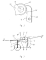
Fig. 1 shows a longitudinal cross-sectional view of a toggle-lever drive device according to the present invention, in the form of a clamping device for clamping work pieces; -
Fig. 2 shows an enlarged detail ofFig. 1 , which illustrates the arched profile of the guide surface for guiding the sliding roller; -
Fig. 3 shows a schematic representation of the toggle-lever mechanism, and of the guide surface for guiding the sliding roller, in which the forces at play between the various members have been indicated schematically; -
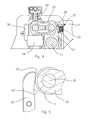
Fig. 4 shows a longitudinal cross-sectional view of a detail of a toggle-lever drive device according to the present invention, in the form of a device for laser welding work pieces made of sheet metal; -
Fig. 5 shows the preferential profile of the guide surface for guiding the sliding roller in the case of devices for laser welding work pieces made of sheet metal; and -
Fig. 6 shows a longitudinal cross-sectional view of a detail of a toggle-lever drive device according to the present invention, in the form of a stamping press device for imprinting reference numbers on sheet metal. - The general features of the present invention will be illustrated hereunder by means of an exemplificative embodiment.
-
Fig. 1 shows a toggle-lever drive device having a rocking work arm, according to the present invention, which is in particular in the form of a clamping device for clamping work pieces, in which an external stop for retaining the work arm is provided; it cannot be excluded however that the drive device may be configured for other uses, for example in the form of a laser welding device, in which the work arm is shaped and disposed for welding work pieces of sheet metal, in which an internal stop for the crank of the toggle and/or an adjustable upper stop are provided, or in the form of a stamping press device for imprinting reference numbers on sheet metal. - The device of
Fig. 1 comprises a box-shaped support body 10 for supporting arocking work arm 11, conformed to clamp work pieces against a shoulder surface forming part of the device itself or provided on a separate structure. - In particular, the
work arm 11 is supported by arotatable drive shaft 13, which is operatively connected to alinear actuator 14 by means of a toggle-lever mechanism 15, in such a way as to drive thearm 11 to rotate between a non-operative position and a working position comprised within a range of angular values, in relation to the operative requirements. - The working position of the
work arm 11 can be precisely set thanks to a stop member or to an adjustable external stop mechanism, for example comprising afirst pin 24, adjustably connected to thework arm 11 by means of a screw thread 24', and a second fixedpin 25 supported by aside protrusion 12 of thebody 10 of the device, theaforesaid pins arm 11 itself, causing it to stop. - The
linear actuator 14, for example in the form of a pneumatic cylinder, is provided with a linearlymovable thrust member 16 to exert an actuating force F, between a backward position and a forward position, in which theclamping arm 11 is in the working position. - The
thrust member 16, at the end facing towards the toggle-lever mechanism 15, is provided with at least one slidingroller 17, having a radius R, pivotally supported on arotational pin 18. - The
sliding roller 17 is movable along at least oneguide surface 19 provided inside the box-shaped body 10, which has an arched profile 19' in correspondence with the forward position of thethrust member 16; preferentially the arched profile 19' is made on aguide cam 20 removably secured within the box-shaped body 10, in such a way as to allow a replacement of the same cam, for example for operative requirements or in the event of wear. - The toggle-
lever mechanism 15 in turn comprises acrank 21 of a length A, connected to thedrive shaft 13 to rotate with theclamping arm 11, and a connectinglink 22 of a length B, connected to thethrust member 16 in correspondence with therotational pin 18 of thesliding roller 17; thecrank 21 and the connectinglink 22 are also connected to each other by means of ahinge pin 23, and form between each other an angle β, as indicated inFig. 3 . - The above toggle-
lever mechanism 15 is of a per se known type, and has a dead centre condition, in which thecrank 21 and the connectinglink 22 are substantially at right angles with each other, with thethrust member 16 in the forward position; in correspondence with this condition, the clampingarm 11 assumes its working position, exerting high operative forces. - The connecting
link 22 of the toggle-lever mechanism 15 can be of the rigid type, as illustrated inFig. 1 , or can advantageously be of a type elastically yielding in the axial direction in a controlled manner, the type being chosen in relation to the operative requirements of the device. - As schematically illustrated in
Fig. 3 , the arched profile 19' of theguide surface 19 exerts on the roller 17 a reaction force Q" orthogonally directed to the tangent at the contact point between the roller and the arched profile itself, and oriented according to an angle α with respect to the longitudinal axis of the connectinglink 22. - According to the present invention, the arched profile 19' of the
guide surface 19, thesliding roller 17, and the connectinglink 22 and thecrank 21 of the toggle-lever mechanism 15 are shaped and disposed in such a way as to define values of the angle α equivalent to or lower than 3°, determining for theclamping arm 11 an operative force Q' according to the following formula:
of a constant value along the entire arched profile 19' of theguide surface 19, where Q = F/senα is the component of the force F exerted by thethrust member 16 on theroller 17, in a direction according to the longitudinal axis of the connectinglink 22. - For the purposes of this description, the expression "force of a constant value" is understood to mean that the force is maintained at a nearly constant value, except for a deviation of a negligible entity with respect to the value of the force itself, for any possible working position of the
clamping arm 11 itself. - For such values of the angle α, equivalent to or lower than 3°, the working position of the
clamping arm 11 proves to be irreversible in the absence of actuating force by thelinear actuator 14, and/or in the presence of high external forces tending to shift thearm 11 itself towards the non-operative position. - As illustrated in
Fig. 3 , for the purposes of this description, a reference system of Cartesian axes X and Y is defined, in which thedrive shaft 13 identifies its origin O, in which the axis Y is directed in the same way as thecrank 21 when the latter is in a vertical position, or substantially so, in correspondence with the working position of theclamping arm 11, and in which the axis X is directed at right angles to the axis Y, towards theguide surface 19. - With reference to said Cartesian axes, the arched profile 19' of the
guide surface 19 is defined by an arc of a circle having its centre C disposed close to thehinge pin 23, in a position lying between thecrank 21 and the connectinglink 22, when the toggle-lever mechanism 15 is in a per se known dead centre condition, in correspondence with the working position of theclamping arm 11; preferentially the centre C is comprised within the following Cartesian coordinate intervals:

where A is, as mentioned, the length of thecrank 21, while B is the length of the connectinglink 22. - The radius R' of the arc of circle is defined by the following relation:

where B is still the length of the connectinglink 22, R is the radius of theroller 17, and Xc is the abscissa of the centre C, in absolute value. - Lastly, the following relation must also be satisfied

- Preferentially, the
crank 21 has a length A ranging from 18 mm to 22 mm, the connectinglink 22 has a length B ranging from 18.5 mm to 22.5 mm, while theroller 17 has a radius R ranging from 7 mm to 9 mm. - As said, the toggle-lever drive device according to the present invention can be configured in the form of a laser welding device for welding superimposed metal sheets; in this case, in place of the external stop mechanism for stopping the
work arm 11, an internal stop for the crank of the toggle-lever mechanism and/or an adjustable upper stop for the thrust member are provided. - In particular, with reference to
Fig. 4 , in which the same numerical references have been used to indicate similar or equivalent parts, the laser welding device comprises astop element 26 for stopping thethrust member 16, which defines the forward position of thethrust member 16 itself; preferentially, thestop element 26 extends into thebody 10 through a hole disposed at the end of thesame body 10 opposite to the linear actuator, and can be screwably adjusted in the direction of the axis of thethrust member 16. - As an alternative or in combination with the
stop element 26, aninternal stop 27 for thecrank 21 of the toggle-lever mechanism 15 can be provided. - In particular, the
internal stop 27, which is interposed between an internal wall of thebody 10 and thecrank 21 itself, comprises amovable plate 28, elastically supported by Bellevillewashers 29, which is pressed by thecrank 21 until it is brought to rest against a stop surface disposed to the rear of theplate 28 itself, thereby causing thework arm 11 to stop in correspondence with the pre-established working position, and allowing to take up every final slack of the linkage of the device. - In the case of the laser welding device, the profile of the
guide surface 19 for guiding thesliding roller 17, preferentially has an arched profile 19' which extends into astraight section 19" in correspondence with the most forward position for thethrust member 16. - The aforesaid straight section 19'', which extends parallel to the axis of the
thrust member 16, enables thework arm 11 to assume an intermediate angular position between an open non-operative position and a closed working position. - In fact, thanks to such configuration of the
guide surface 19, when thethrust member 16 moves towards its forward position, thesliding roller 17 first comes in correspondence with the curved profile 19', where thework arm 11 assumes a closed working position in which it grips the superimposed edges of the metal sheets, elastically deforming them until they come into contact. - Subsequently, when the
thrust member 16 moves to its most forward position, against thestop element 26, thesliding roller 17 comes in correspondence with thestraight section 19", where thework arm 11 assumes an intermediate angular position, rising in a controlled manner to enable the edges of the metal sheets to dispose themselves at a distance δ from one another, thanks to their elastic recovery; by maintaining the metal sheets spaced apart from one another, it is possible to carry out a laser welding with high strength and surface finish features, in that the gases that are given off during the welding, which are responsible for erosion and perforation of the metal, are thus efficiently removed. - Thanks to the adjustment by screwing of the
stop element 26, it is possible to vary the stop position of thethrust member 16, thereby defining various intermediate positions for thework arm 11, in relation to the operative requirements. - As said above, the toggle-lever drive device according to the present invention can also be configured in the form of a stamping press device for marking reference numbers or other references on sheet metal.
- In this case, as illustrated in
Fig. 6 , in which the same numerical references have been used to indicate similar or equivalent parts, therocking work arm 11 of the drive device supports a marking orstamping tool 30 which cooperates with aside shoulder 31 of the device, or with a separated anvil, to mark a sheet metal disposed therebetween. - The marking
tool 30 comprises a rotatably supported markingdrum 32 which can be rotated by aside lever 33 in order to automatically change the reference number of thetool 30 at each rocking movement of thework arm 11. - In particular, the
side lever 33 is actuated at the non-operative position of thework arm 11 by a protrudingstem 34 connected to thebody 10 of the device, thereby rotating thedrum 32 or a part thereof. - The shape and arrangement of the arched profile 19' of the
guide surface 19, the slidingroller 17, and the connectinglink 22 and the crank 21 of the toggle-lever mechanism is the same as described above with reference to the first embodiment of the invention. - Therefore, since the
work arm 11 of the device according to the invention exerts a constant operative force for any possible working position of thearm 11, a same marking pressure value is applied on the sheet metal by the markingtool 30, also in the case of different thicknesses of the sheet metal, avoiding any undesired or uncontrolled deformation of the sheet metal. - Furthermore, the use of a connecting
link 22 of the type elastically yielding in axial direction in a controlled mode, allows to equalize in a better way the mechanical stresses within the toggle-lever mechanism and consequently the operative force for thework arm 11; furthermore, such a connectinglink 22 reduces the effort necessary for moving thework arm 11 from the working position to the non-operative position, avoiding any blocking of thework arm 11 in the working position. - A toggle-lever drive device configured according to the present invention, allows the work arm to exert an operative force of an effectively constant value for any possible working position of the arm itself; moreover, the working position assumed by the work arm is irreversibly maintained, in the absence of actuating force by the linear actuator, or in the event of high forces tending to move the arm towards the non-operative position.
- What has been described and shown with reference to the accompanying drawings, has been given purely by way of example and in order to illustrate the general characteristics of the invention, as well as one of its preferential embodiments; therefore, other modifications and variations to the toggle-lever drive device are possible, without thereby deviating from the scope of the claims.
Claims (7)
- A toggle-lever drive device having a rocking work arm (11), of the type comprising a pivotally supported work arm (11), operatively connected to a linear actuator (14) by a toggle-lever mechanism (15), to rotate between a non-operative position and a working position comprised within a range of angular values, said linear actuator (14) being provided with a linearly movable thrust member (16) to exert an actuating force F, between a backward position and a forward position, in which the work arm (11) is in said working position, said thrust member (16) being provided with at least one sliding roller (17) having a radius R, movable along at least one guide surface (19) having an arched profile (19') in correspondence with said forward position of the thrust member (16), said toggle-lever mechanism (15) comprising a crank (21) and a connecting link (22) articulated to each other and forming an angle β,
in which the arched guide surface (19') exerts on the roller (17) a reaction force Q" oriented according to an angle α with respect to said connecting link (22),
characterised in that the arched profile (19') of the guide surface (19), the sliding roller (17), as well as the connecting link (22) and the crank (21) of said toggle-lever mechanism (15) are shaped and disposed in such a way as to define values of the angle α equivalent to or lower than 3°, determining for said work arm (11) an operative force Q' according to the following formula:
of a constant value along the entire arched profile (19') of the guide surface (19), and
in that for said values of the angle α equivalent to or lower than 3°, the working position of the work arm (11) is irreversible in the absence of actuating force by said linear actuator (11). - Toggle-lever drive device according to claim 1, in which the work arm (11) is supported by a rotatable drive shaft (13), and in which the toggle-lever mechanism (15) comprises a crank (21) of a length A, connected to said drive shaft (13), and a connecting link (22) of a length B connected to the thrust member (16) in correspondence with said sliding roller (17), said drive shaft (13) defining the origin O of a reference system of Cartesian axes X and Y, in which the axis Y is directed in the same way as said crank (21) when the latter is in a vertical position in correspondence with said working position of the work arm (11), and the axis X is directed towards said guide surface (19),
characterised in that the arched profile (19') of the guide surface (19) is defined by an arc of a circle having a centre C comprised within the following Cartesian coordinate intervals:

and having a radius R' defined by the following relation:
where Xc is the abscissa of the centre C, in absolute value, and in which the following relation is further satisfied
- Toggle-lever drive device according to claim 2,
characterised in that said crank (21) has a length A ranging from 18 mm to 22 mm,
in that said connecting link (22) has a length B ranging from 18.5 mm to 22.5 mm, and
in that said roller (17) has a radius R ranging from 7 mm to 9 mm. - Toggle-lever drive device according to any one of the previous claims, characterised by being in the form of a clamping device for clamping work pieces, in which said work arm (11) is shaped and disposed for clamping work pieces and in which an external stop mechanism (24, 25) is provided for stopping the work arm (11) in said working position.
- Toggle-lever drive device according to any one of the claims from 1 to 3, characterised by being in the form of a laser welding device, in which said work arm (11) is shaped and disposed for welding work pieces of sheet metal and in which an internal stop (27) for the crank (21) of the toggle-lever mechanism (15) and/or an adjustable upper stop (26) for the thrust member (16) of the actuator (14) are provided.
- Toggle-lever drive device according to claim 5,
characterised in that the guide surface (19) for guiding the sliding roller (17), has an arched profile (19') which extends into a straight section (19'') in correspondence with the most forward position for said thrust member (16). - Toggle-lever drive device according to any one of the claims from 1 to 3, characterised by being in the form of a stamping press device for marking reference numbers on sheet metal, comprising a stamping tool (30) supported by said work arm (11) and a shoulder member (31) cooperating with said stamping tool (30) for marking a sheet metal arranged therebetween.
Priority Applications (1)
| Application Number | Priority Date | Filing Date | Title |
|---|---|---|---|
| EP08018026A EP2177320A1 (en) | 2008-10-15 | 2008-10-15 | Irreversible-type toggle-lever drive device |
Applications Claiming Priority (1)
| Application Number | Priority Date | Filing Date | Title |
|---|---|---|---|
| EP08018026A EP2177320A1 (en) | 2008-10-15 | 2008-10-15 | Irreversible-type toggle-lever drive device |
Publications (1)
| Publication Number | Publication Date |
|---|---|
| EP2177320A1 true EP2177320A1 (en) | 2010-04-21 |
Family
ID=40435799
Family Applications (1)
| Application Number | Title | Priority Date | Filing Date |
|---|---|---|---|
| EP08018026A Withdrawn EP2177320A1 (en) | 2008-10-15 | 2008-10-15 | Irreversible-type toggle-lever drive device |
Country Status (1)
| Country | Link |
|---|---|
| EP (1) | EP2177320A1 (en) |
Cited By (3)
| Publication number | Priority date | Publication date | Assignee | Title |
|---|---|---|---|---|
| EP3061568A1 (en) * | 2015-02-26 | 2016-08-31 | UNIVER S.p.A. | Clamping device for clamping workpieces of variable thickness |
| ITUB20153120A1 (en) * | 2015-08-13 | 2017-02-13 | Pneumax S P A | ACTUATION TYPE ACTUATED UNIT WITH OPTIMIZED EFFICIENCY |
| US10544813B2 (en) | 2016-07-28 | 2020-01-28 | Energium Co., Ltd. | Electrical clamping apparatus |
Citations (8)
| Publication number | Priority date | Publication date | Assignee | Title |
|---|---|---|---|---|
| US4921233A (en) * | 1988-05-06 | 1990-05-01 | Genus International | Clamping device for plates or profiled elements placed one against the other |
| DE29713944U1 (en) * | 1997-08-05 | 1997-10-02 | Tuenkers Maschinenbau Gmbh | Fluid-operated knee lever clamping device |
| EP0836912A1 (en) | 1996-10-15 | 1998-04-22 | Robotic | Clamping device of the kind comprising a piston actuated lever |
| WO2000044531A1 (en) * | 1999-01-27 | 2000-08-03 | Festo Ag & Co. | Articulated lever tensioning device |
| US6206353B1 (en) * | 1997-07-29 | 2001-03-27 | Benteler Werke Ag | Clamping device for structural components |
| EP1350591A1 (en) * | 2002-04-02 | 2003-10-08 | Luciano Migliori | clamping device for laser welding |
| US20040113342A1 (en) * | 2001-12-06 | 2004-06-17 | Josef-Gerhard Tunkers | Power-driven toggle-lever clamping device |
| DE102004007346B3 (en) * | 2003-11-04 | 2005-04-21 | Tünkers Maschinenbau Gmbh | Road vehicle bodywork manufacturing tool with knee joint clamping system and point welding tool has cylinder with working piston and braking piston with piston rod fitting in bore in working piston rod |
-
2008
- 2008-10-15 EP EP08018026A patent/EP2177320A1/en not_active Withdrawn
Patent Citations (8)
| Publication number | Priority date | Publication date | Assignee | Title |
|---|---|---|---|---|
| US4921233A (en) * | 1988-05-06 | 1990-05-01 | Genus International | Clamping device for plates or profiled elements placed one against the other |
| EP0836912A1 (en) | 1996-10-15 | 1998-04-22 | Robotic | Clamping device of the kind comprising a piston actuated lever |
| US6206353B1 (en) * | 1997-07-29 | 2001-03-27 | Benteler Werke Ag | Clamping device for structural components |
| DE29713944U1 (en) * | 1997-08-05 | 1997-10-02 | Tuenkers Maschinenbau Gmbh | Fluid-operated knee lever clamping device |
| WO2000044531A1 (en) * | 1999-01-27 | 2000-08-03 | Festo Ag & Co. | Articulated lever tensioning device |
| US20040113342A1 (en) * | 2001-12-06 | 2004-06-17 | Josef-Gerhard Tunkers | Power-driven toggle-lever clamping device |
| EP1350591A1 (en) * | 2002-04-02 | 2003-10-08 | Luciano Migliori | clamping device for laser welding |
| DE102004007346B3 (en) * | 2003-11-04 | 2005-04-21 | Tünkers Maschinenbau Gmbh | Road vehicle bodywork manufacturing tool with knee joint clamping system and point welding tool has cylinder with working piston and braking piston with piston rod fitting in bore in working piston rod |
Cited By (4)
| Publication number | Priority date | Publication date | Assignee | Title |
|---|---|---|---|---|
| EP3061568A1 (en) * | 2015-02-26 | 2016-08-31 | UNIVER S.p.A. | Clamping device for clamping workpieces of variable thickness |
| ITUB20153120A1 (en) * | 2015-08-13 | 2017-02-13 | Pneumax S P A | ACTUATION TYPE ACTUATED UNIT WITH OPTIMIZED EFFICIENCY |
| EP3130809A1 (en) * | 2015-08-13 | 2017-02-15 | Pneumax S.p.A. | Optimized efficiency actuating unit of the articulated lever type |
| US10544813B2 (en) | 2016-07-28 | 2020-01-28 | Energium Co., Ltd. | Electrical clamping apparatus |
Similar Documents
| Publication | Publication Date | Title |
|---|---|---|
| EP2983844B1 (en) | Punch apparatus | |
| EP3006168A2 (en) | Gripper | |
| EP2452761B1 (en) | Clinch clamp | |
| KR20050012129A (en) | Toggle-lever clamping device for clamping work pieces with self-compensation | |
| KR101331474B1 (en) | Method of holding band saw blade by means of band saw blade guide device, as well as band saw blade guide device | |
| US20060096957A1 (en) | Clamping device for processing work pieces | |
| US10174820B2 (en) | Actuating device of the articulated lever or cam type for the precise positioning of a pivotable arm | |
| WO2015064590A1 (en) | Cutting device | |
| US6739587B2 (en) | Toggle lever clamping device | |
| EP2177320A1 (en) | Irreversible-type toggle-lever drive device | |
| US7290816B2 (en) | Work piece gripping device for robotized manipulating systems | |
| US7258030B2 (en) | Failsafe element for rotary cam unit used in a flanged die | |
| JP5690950B2 (en) | Mold with circular cam device | |
| DE102018002358B4 (en) | Toggle lever clamping device, for use in the body shop of the automotive industry with an additional abutment on the toggle joint element | |
| EP3078453B1 (en) | Actuating device of the articulated lever or cam type for the precise positioning of a pivotable arm | |
| AU677400B2 (en) | Machining tool for work pieces | |
| US5948284A (en) | Equalizing cam rocker fixture assembly for a resistance welding gun | |
| US20050252269A1 (en) | Toggle press | |
| ITMI20070774A1 (en) | IRREVERSIBLE KNEE CONTROL DEVICE | |
| JP2018187648A (en) | Die fitting device | |
| JP5525829B2 (en) | Band saw blade clamping method by band saw blade guide device and band saw blade guide device | |
| JP2023122372A (en) | Clamp device | |
| JP2011067831A (en) | Bending machine | |
| JPH0751220Y2 (en) | Work clamp device | |
| KR20190048237A (en) | pre-pressure device of ball screw |
Legal Events
| Date | Code | Title | Description |
|---|---|---|---|
| PUAI | Public reference made under article 153(3) epc to a published international application that has entered the european phase |
Free format text: ORIGINAL CODE: 0009012 |
|
| AK | Designated contracting states |
Kind code of ref document: A1 Designated state(s): AT BE BG CH CY CZ DE DK EE ES FI FR GB GR HR HU IE IS IT LI LT LU LV MC MT NL NO PL PT RO SE SI SK TR |
|
| AX | Request for extension of the european patent |
Extension state: AL BA MK RS |
|
| AKY | No designation fees paid | ||
| REG | Reference to a national code |
Ref country code: DE Ref legal event code: 8566 |
|
| STAA | Information on the status of an ep patent application or granted ep patent |
Free format text: STATUS: THE APPLICATION IS DEEMED TO BE WITHDRAWN |
|
| 18D | Application deemed to be withdrawn |
Effective date: 20101022 |