EP2176113B1 - Acoustic baffle - Google Patents
Acoustic baffle Download PDFInfo
- Publication number
- EP2176113B1 EP2176113B1 EP07801691A EP07801691A EP2176113B1 EP 2176113 B1 EP2176113 B1 EP 2176113B1 EP 07801691 A EP07801691 A EP 07801691A EP 07801691 A EP07801691 A EP 07801691A EP 2176113 B1 EP2176113 B1 EP 2176113B1
- Authority
- EP
- European Patent Office
- Prior art keywords
- heat expandable
- carrier plate
- central section
- baffle
- mean plane
- Prior art date
- Legal status (The legal status is an assumption and is not a legal conclusion. Google has not performed a legal analysis and makes no representation as to the accuracy of the status listed.)
- Not-in-force
Links
- 239000000463 material Substances 0.000 claims abstract description 65
- 238000007789 sealing Methods 0.000 claims abstract description 16
- 238000009826 distribution Methods 0.000 claims abstract description 11
- 238000013016 damping Methods 0.000 claims description 13
- 230000005484 gravity Effects 0.000 claims description 8
- 229920000642 polymer Polymers 0.000 claims description 8
- 239000004604 Blowing Agent Substances 0.000 claims description 7
- 238000002844 melting Methods 0.000 claims description 3
- 230000008018 melting Effects 0.000 claims description 3
- 239000004952 Polyamide Substances 0.000 claims description 2
- 239000000654 additive Substances 0.000 claims description 2
- 239000003431 cross linking reagent Substances 0.000 claims description 2
- 229920002647 polyamide Polymers 0.000 claims description 2
- 230000000996 additive effect Effects 0.000 claims 1
- 229920001038 ethylene copolymer Polymers 0.000 claims 1
- 230000005540 biological transmission Effects 0.000 description 11
- 239000003566 sealing material Substances 0.000 description 10
- 239000000945 filler Substances 0.000 description 6
- 238000000034 method Methods 0.000 description 6
- 238000010276 construction Methods 0.000 description 5
- 238000003780 insertion Methods 0.000 description 5
- 230000037431 insertion Effects 0.000 description 5
- 229920001169 thermoplastic Polymers 0.000 description 5
- 239000012530 fluid Substances 0.000 description 4
- 238000001746 injection moulding Methods 0.000 description 4
- 239000000203 mixture Substances 0.000 description 4
- 238000003860 storage Methods 0.000 description 4
- 239000004416 thermosoftening plastic Substances 0.000 description 4
- 230000004913 activation Effects 0.000 description 3
- 229920001577 copolymer Polymers 0.000 description 3
- 239000004033 plastic Substances 0.000 description 3
- 229920003023 plastic Polymers 0.000 description 3
- OZAIFHULBGXAKX-UHFFFAOYSA-N 2-(2-cyanopropan-2-yldiazenyl)-2-methylpropanenitrile Chemical compound N#CC(C)(C)N=NC(C)(C)C#N OZAIFHULBGXAKX-UHFFFAOYSA-N 0.000 description 2
- KAKZBPTYRLMSJV-UHFFFAOYSA-N Butadiene Chemical compound C=CC=C KAKZBPTYRLMSJV-UHFFFAOYSA-N 0.000 description 2
- VGGSQFUCUMXWEO-UHFFFAOYSA-N Ethene Chemical compound C=C VGGSQFUCUMXWEO-UHFFFAOYSA-N 0.000 description 2
- 239000005977 Ethylene Substances 0.000 description 2
- RRHGJUQNOFWUDK-UHFFFAOYSA-N Isoprene Chemical compound CC(=C)C=C RRHGJUQNOFWUDK-UHFFFAOYSA-N 0.000 description 2
- PPBRXRYQALVLMV-UHFFFAOYSA-N Styrene Chemical compound C=CC1=CC=CC=C1 PPBRXRYQALVLMV-UHFFFAOYSA-N 0.000 description 2
- 238000004026 adhesive bonding Methods 0.000 description 2
- 229920001400 block copolymer Polymers 0.000 description 2
- 229910052799 carbon Inorganic materials 0.000 description 2
- 239000000356 contaminant Substances 0.000 description 2
- 238000001125 extrusion Methods 0.000 description 2
- 239000006260 foam Substances 0.000 description 2
- 238000005984 hydrogenation reaction Methods 0.000 description 2
- 230000014759 maintenance of location Effects 0.000 description 2
- -1 polyoxypropylene Polymers 0.000 description 2
- 238000010008 shearing Methods 0.000 description 2
- XLYOFNOQVPJJNP-UHFFFAOYSA-N water Substances O XLYOFNOQVPJJNP-UHFFFAOYSA-N 0.000 description 2
- 238000003466 welding Methods 0.000 description 2
- NBOCQTNZUPTTEI-UHFFFAOYSA-N 4-[4-(hydrazinesulfonyl)phenoxy]benzenesulfonohydrazide Chemical compound C1=CC(S(=O)(=O)NN)=CC=C1OC1=CC=C(S(=O)(=O)NN)C=C1 NBOCQTNZUPTTEI-UHFFFAOYSA-N 0.000 description 1
- 241000191291 Abies alba Species 0.000 description 1
- NLHHRLWOUZZQLW-UHFFFAOYSA-N Acrylonitrile Chemical compound C=CC#N NLHHRLWOUZZQLW-UHFFFAOYSA-N 0.000 description 1
- 239000004156 Azodicarbonamide Substances 0.000 description 1
- UGFAIRIUMAVXCW-UHFFFAOYSA-N Carbon monoxide Chemical compound [O+]#[C-] UGFAIRIUMAVXCW-UHFFFAOYSA-N 0.000 description 1
- MWRWFPQBGSZWNV-UHFFFAOYSA-N Dinitrosopentamethylenetetramine Chemical compound C1N2CN(N=O)CN1CN(N=O)C2 MWRWFPQBGSZWNV-UHFFFAOYSA-N 0.000 description 1
- YUBJPYNSGLJZPQ-UHFFFAOYSA-N Dithiopyr Chemical compound CSC(=O)C1=C(C(F)F)N=C(C(F)(F)F)C(C(=O)SC)=C1CC(C)C YUBJPYNSGLJZPQ-UHFFFAOYSA-N 0.000 description 1
- CERQOIWHTDAKMF-UHFFFAOYSA-N Methacrylic acid Chemical compound CC(=C)C(O)=O CERQOIWHTDAKMF-UHFFFAOYSA-N 0.000 description 1
- 239000004642 Polyimide Substances 0.000 description 1
- 229920001328 Polyvinylidene chloride Polymers 0.000 description 1
- YXFVVABEGXRONW-UHFFFAOYSA-N Toluene Chemical compound CC1=CC=CC=C1 YXFVVABEGXRONW-UHFFFAOYSA-N 0.000 description 1
- 150000001252 acrylic acid derivatives Chemical class 0.000 description 1
- 230000003213 activating effect Effects 0.000 description 1
- XOZUGNYVDXMRKW-AATRIKPKSA-N azodicarbonamide Chemical compound NC(=O)\N=N\C(N)=O XOZUGNYVDXMRKW-AATRIKPKSA-N 0.000 description 1
- 235000019399 azodicarbonamide Nutrition 0.000 description 1
- 239000011324 bead Substances 0.000 description 1
- 229910002091 carbon monoxide Inorganic materials 0.000 description 1
- 239000000969 carrier Substances 0.000 description 1
- 239000012876 carrier material Substances 0.000 description 1
- 239000002666 chemical blowing agent Substances 0.000 description 1
- 230000006835 compression Effects 0.000 description 1
- 238000007906 compression Methods 0.000 description 1
- 238000005260 corrosion Methods 0.000 description 1
- 230000007797 corrosion Effects 0.000 description 1
- 239000007822 coupling agent Substances 0.000 description 1
- 238000000354 decomposition reaction Methods 0.000 description 1
- 238000005238 degreasing Methods 0.000 description 1
- 229910000267 dualite Inorganic materials 0.000 description 1
- 239000000428 dust Substances 0.000 description 1
- 230000000694 effects Effects 0.000 description 1
- 238000005187 foaming Methods 0.000 description 1
- 239000007789 gas Substances 0.000 description 1
- 238000010438 heat treatment Methods 0.000 description 1
- 239000011796 hollow space material Substances 0.000 description 1
- 238000009413 insulation Methods 0.000 description 1
- 238000005304 joining Methods 0.000 description 1
- 238000004519 manufacturing process Methods 0.000 description 1
- 229910052751 metal Inorganic materials 0.000 description 1
- 239000002184 metal Substances 0.000 description 1
- 239000011325 microbead Substances 0.000 description 1
- 239000003973 paint Substances 0.000 description 1
- 230000035515 penetration Effects 0.000 description 1
- 230000002093 peripheral effect Effects 0.000 description 1
- 239000004014 plasticizer Substances 0.000 description 1
- 229920000139 polyethylene terephthalate Polymers 0.000 description 1
- 239000005020 polyethylene terephthalate Substances 0.000 description 1
- 229920001721 polyimide Polymers 0.000 description 1
- 238000006116 polymerization reaction Methods 0.000 description 1
- 229920001451 polypropylene glycol Polymers 0.000 description 1
- 229920002742 polystyrene-block-poly(ethylene/propylene) -block-polystyrene Polymers 0.000 description 1
- 239000005033 polyvinylidene chloride Substances 0.000 description 1
- 229920005604 random copolymer Polymers 0.000 description 1
- 230000002787 reinforcement Effects 0.000 description 1
- 230000003014 reinforcing effect Effects 0.000 description 1
- 239000012779 reinforcing material Substances 0.000 description 1
- 239000007787 solid Substances 0.000 description 1
- 239000000243 solution Substances 0.000 description 1
- 229920001935 styrene-ethylene-butadiene-styrene Polymers 0.000 description 1
- 239000000126 substance Substances 0.000 description 1
- 230000001629 suppression Effects 0.000 description 1
- 239000012815 thermoplastic material Substances 0.000 description 1
- 229940117958 vinyl acetate Drugs 0.000 description 1
- 239000011800 void material Substances 0.000 description 1
- 238000009736 wetting Methods 0.000 description 1
Images


Classifications
-
- B—PERFORMING OPERATIONS; TRANSPORTING
- B60—VEHICLES IN GENERAL
- B60R—VEHICLES, VEHICLE FITTINGS, OR VEHICLE PARTS, NOT OTHERWISE PROVIDED FOR
- B60R13/00—Elements for body-finishing, identifying, or decorating; Arrangements or adaptations for advertising purposes
- B60R13/08—Insulating elements, e.g. for sound insulation
-
- B—PERFORMING OPERATIONS; TRANSPORTING
- B62—LAND VEHICLES FOR TRAVELLING OTHERWISE THAN ON RAILS
- B62D—MOTOR VEHICLES; TRAILERS
- B62D29/00—Superstructures, understructures, or sub-units thereof, characterised by the material thereof
- B62D29/001—Superstructures, understructures, or sub-units thereof, characterised by the material thereof characterised by combining metal and synthetic material
- B62D29/002—Superstructures, understructures, or sub-units thereof, characterised by the material thereof characterised by combining metal and synthetic material a foamable synthetic material or metal being added in situ
-
- B—PERFORMING OPERATIONS; TRANSPORTING
- B60—VEHICLES IN GENERAL
- B60R—VEHICLES, VEHICLE FITTINGS, OR VEHICLE PARTS, NOT OTHERWISE PROVIDED FOR
- B60R13/00—Elements for body-finishing, identifying, or decorating; Arrangements or adaptations for advertising purposes
- B60R13/08—Insulating elements, e.g. for sound insulation
- B60R13/0815—Acoustic or thermal insulation of passenger compartments
Definitions
- the present invention relates to acoustically active and sealing baffles in the cavities of structural components of vehicles.
- Modern vehicle concepts and structural designs of vehicles have a plurality of cavities which have to be sealed in order to prevent the ingress of moisture and contaminants, since the latter can result in corrosion from the inside on the corresponding body parts.
- space frames With the latter, use is made of a lightweight, structurally solid chassis made of prefabricated hollow sections.
- Such constructions have, depending upon the specific system, a number of cavities which have to be sealed against the penetration of moisture and contaminants.
- These cavities include the upwardly extending A-, B- and C-pillars supporting the roof structure, the roof rail, portions of the fenders, or the sill.
- these cavities transmit airborne sound in the form of unpleasant vehicle running noises and wind noises. Therefore, such sealing measures also serve to reduce the noises and to enhance the comfort of travelling in the vehicle.
- these frame parts and body parts containing cavities are prefabricated from half-shell components which were joined at a later time by welding and/or adhesive bonding so as to form the closed hollow section.
- such half-shell components after joining are called “interconnected walls", which surround the enclosed hollow section ("cavity").
- interconnected walls which surround the enclosed hollow section.
- baffles are designed to include a sealing material disposed on a support member or carrier.
- the carrier is generally manufactured from a rigid material, such as hard plastic, such that its shape approximates the shape of the cavity to be sealed.
- the carrier/sealing material combination is configured such that the carrier is inserted into a cavity.
- the sealing material is activated (thermally or chemically) to expand (or "foam") after insertion into the cavity so that the sealing material forms a seal with the walls of the cavity.
- the expanded sealing material creates an airtight seal between the carrier and the walls of the cavity.
- a cavity sealing article which comprises a planar support member and a sealing member comprising a foamable polymer which surrounds in an intimate contact the support member and which is in plane with the support member.
- the foamable polymer comprises at least two layers which are in intimate contact and which are in the plane of the support member.
- the outer most layer of the sealing member comprises an un-cross linked foamable polymer and the inner layer comprises a cross linked foamable polymer.
- WO 00/03894 A1 discloses a lightweight expandable baffle for sealing a cavity of a vehicle body at a predetermined cross section of the cavity.
- This baffle includes a rigid support plate having an outer periphery with a shape generally corresponding to but smaller than the shape of the cross section of the cavity.
- Said baffle comprises a heat expandable sealing material mounted to the outer periphery of the rigid support plate having an activation temperature range at which the material expands.
- the support plate is being formed of a material having a higher melting point than the activation temperature range of the sealing material. When activated, the sealing material expands radially from the rigid support plate to fill the cross-sectional cavity between the rigid support plate and the cavity walls.
- WO 01/83206 A1 discloses a combined baffle and reinforcing assembly for use within the cavity of a structural member to dampen acoustic transmissions through the cavity and to provide reinforcement in a direction transverse to the longitudinal axis of the structural member.
- the combined assembly includes a synthetic carrier which comprises an interior area, a marginal rim and an attachment member preferably in a form of a clip suited for insertion to the corresponding hole in the wall of the structural member.
- the carrier is circumscribed by a continuous band of reinforcing material extending around the periphery of the carrier.
- the marginal rim of the carrier may include a base wall and a support flange for receiving the thermally expandable material thereon.
- WO 01/71225 describes an expandable baffle part for sealing cavities in automobiles.
- This part comprises a thermally expandable sealing material that is able to expand at the temperatures of the e-coat bake oven.
- the baffle part comprises a support which positions and fixes the expandable material at the predetermined point in the cavity until the thermal expansion sets in.
- the support further has at least one clip or a snap-action or plug-in device which is inserted under pressure into a corresponding bore or aperture in the hollow-space structure in order to fix the component.
- the carrier for the thermally expandable sealing material is usually plate-like and flat.
- the baffle is inserted into the longitudinal cavity in a way that the plane of the carrier lies perpendicular to the longitudinal axis of the cavity, so that the cavity is bisected by the baffle.
- WO-A-99/37506 discloses a heat expandable baffle for sealing automotive cavities formed by interconnected walls, to be fixed essentially inside the cavity to be sealed, with the possible exception of fasteners which may penetrate a wall of the cavity for fixing the baffle prior to expanding the heat expandable material, the baffle comprising a carrier plate with an outer perimeter and a strand of a heat expandable material along the major part of the outer perimeter, this strand circumscribing a central section of the carrier plate which is not covered by the heat expandable material, the outer perimeter defining a mean plane limited by the outer perimeter, wherein the central section has a lumped mass distribution.
- US 4901395 describes a grommet for mounting in an opening in a compartment wall and including an elastomeric body having a passage therethrough for passing an elongated member through the compartment wall, such grommet comprising:
- the grommet is configured for sealing a (essentially two-dimensional) hole in a wall, not for sealing a (essentially three-dimensional) usually longitudinal cavity formed by interconnecting walls. It does not comprise a carrier plate (which is a flat object), but is an essentially three-dimensional object.
- the expandable material is not disposed along the outer perimeter of the plate, as it is the case for a baffle, but is essentially placed around the thinnest section of the grommet.
- the grommet has at least one flange portion which is larger than the opening to be sealed, whereas the baffle is essentially inside the cavity to be sealed, with the possible exception of fasteners which may penetrate a wall of the cavity for fixing the baffle prior to expanding the heat expandable material.
- baffles While the above mentioned baffles have been successfully employed to seal automotive body cavities against the intrusion of dust, water, carbon monoxide and to a certain extent noise, a need exists for an improved baffle with enhanced sound suppression capability.
- the baffle comprising a carrier plate with an outer perimeter and a strand of a heat expandable material (also called “thermally expandable material” or “foamable material”) along the major part of the outer perimeter, this strand circumscribing a central section of the carrier plate which is not covered by the heat expandable material, the outer perimeter defining a mean plane limited by the outer perimeter, the central section of the carrier plate being bent away from the mean plane in a way that the point on the central section which has the greatest distance from the mean plane lies at a distance from the mean plane which is at least 5 % of the maximum linear length of the carrier plate,.
- the strand of the heat expandable material is disposed along at
- the baffle comprises a support structure along the outer perimeter, said support structure holding the strand of the heat expandable material.
- An automotive cavity is formed by interconnected walls (e.g. two prefabricated half-shells joined together) and has a three-dimensional extension, usually in the form of a straight or bent channel. Examples of such cavities are the hollow spaces within the pillars or other support frames of a vehicle.
- Fig. 1 shows some locations where baffles (30) may be mounted into cavities of a car body. A (essentially two-dimensional) hole in a sheet is not a cavity in the sense of this invention. The baffle is located essentially completely inside the cavity, with the possible exception of fasteners which may penetrate a wall of the cavity for fixing the baffle prior to expanding the heat expandable material.
- a baffle does not exhibit a flange portion with a diameter greater than the "opening" to be sealed, as it has to fit essentially completely inside the cavity, with the possible exceptions of fasteners which are small compared with the complete baffle.
- a plate is defined as a structure having a thickness in a direction of minimum extension (called the "perpendicular plate axis") which is at most 10 % of the length of the structure in the direction of its maximum length, and at most 25 % of the minimum width of the structure in a direction perpendicular to the "perpendicular plate axis".
- the plate is flat, with the exception of the support structure which might stick out of the plate.
- the central section of the carrier plate is bent to form a vaulted or "bowl-like” structure, so that the plate has a convex "upper” and a concave “lower” surface.
- the plate may exhibit a lumped mass distribution. This means that the mass of the plate is not distributed equally, but a part of the mass is concentrated around one or more selected points. Especially, the mass may be concentrated around the centre of gravity of the plate or, if the plate is bent, around the point on the plate which is closest to the centre of gravity of the bent structure.
- the grommet described in US 4901395 is not a plate, but a three-dimensional object.
- the mean plane formed by the outer perimeter of the carrier plate is defined as the least squares plane through six points on the perimeter of the carrier plate, two of these points being located at opposite ends of the line spanning the longest extension of the carrier plate, and the remaining four points lying at the intersection of two further lines with the perimeter of the carrier plate, these two further lines forming angles of 60 ° and 120° with the line spanning the longest extension of the plate, and intersecting this line at its midpoint.
- the least squares plane through six points is the plane which is oriented in such a way that the sum of the squares of the perpendicular distance of each of these points from the plane is minimal. Only the carrier plate, without the support structure, is taken for the definition of the mean plane.
- the six points which define the mean plane are supposed to lie on the outer perimeter of the carrier plate at half the thickness of the carrier plate at the outer perimeter. This is shown schematically in Fig. 2 .
- Line A-A' spans the longest extensions of the carrier plate 21.
- Lines B-B' and C-C' intersect line A-A' in its midpoint at an angle of 60 ° each.
- the mean plane of carrier plate 21 is the least squares plane through the six points A, B, C, A', B', and C' on the perimeter 23 of the carrier plate, supposed to lie at half the thickness of the plate.
- the complete outer perimeter of the carrier plate lies within one plane.
- the six points A, B, C, A', B', and C' on the perimeter 23 of the carrier plate all lie within this plane, and the "mean plane" is the plane which contains the complete perimeter of the carrier plate.
- the central section of carrier plate is bent to form a vaulted or "bowl-like” structure, so that the plate has a convex "upper” and a concave “lower” surface.
- the "upper” surface is the surface pointing away from the mean plane, the “lower” surface is the surface facing the mean plane.
- a void volume can be defined which is limited by the lower surface of the bent carrier plate and by the mean plane.
- the central section of the carrier plate is bent away from the mean plane in such a way that the point on the central section which has the greatest distance from the mean plane lies at a distance from the mean plane which is at least 5 %, but not more than 50 % of the maximum linear length of the carrier plate. This results in a vault-like structure if the carrier plate has essentially the same thickness everywhere.
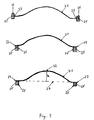
- Fig. 3 shows cross sections of three embodiments of a baffle with a carrier plate 21 having an outer perimeter 23, the carrier plate 21 being bent away from the mean plane 27 through the outer perimeter so that the point 22 on the central section of the carrier plate with the greatest distance from the mean plane 27 lies at a distance ("height") h above the mean plane.
- a "curvature ratio" c can be defined as follows: First, a "hydraulic radius” or “equivalent radius” R is defined. This is the radius of a (theoretical) circle having the same surface area as the central section of the carrier plate, projected onto the "mean plane".
- the "curvature ratio" in the sense of this invention is an indicator for the deviation of the central part of the carrier from being flat and is defined as the fraction h/R, i.e the maximum height h above the mean plane, divided by the hydraulic radius R.
- Different types of support structures 26 are integrally moulded onto the carrier plate 21 to hold the strand of heat expandable material 25.
- the central section of the carrier plate may have an uneven ("lumped") mass distribution. This means that the thickness of the carrier plate is different in various locations.
- the central section of the carrier plate has a lumped mass distribution (i.e. the greatest thickness) which is located at the centre of gravity of the central section or, if the centre of gravity of the central section lies outside of the plate, at the point on the plate which is closest to the centre of gravity of the central section.
- a “lumped mass distribution” in the sense of this invention is defined as an uneven distribution of the mass of the central section of the carrier plate.
- 2% to 50 %, preferably 5 % to 10 % of the total mass of the central section of the carrier plate is “lumped” (aggregated) in the central section of the carrier plate. This means that the mass of those parts of the central section of the carrier plate which have a thickness which is greater than the average thickness is by 2% to 50 %, preferably by 5 % to 10 % larger than it would be if the mass distribution of the central section of the carrier plate would be uniform.
- the carrier plate may be formed from metal or preferably from thermoplastics, in which case the thermoplastics may optionally be fiber-reinforced.
- Preferred thermoplastics are polyamides, polyimides, polyoxypropylene or polyethylene terephthalate.
- the thermoplast should have a melting point higher than the expansion temperature of the heat expandable material.
- the carrier plate, optionally including the support structure, is preferably made by injection moulding.
- the thermoplastic carrier plate and the heat expandable material are either formed in one co-extrusion process or in subsequent extrusion processes on the same injection moulding unit.
- the baffle comprises at least one attachment member or fastener for securing the baffle in the cavity.
- Any of the devices known in the art to be capable of securing a carrier bearing an expandable material to the interior wall of a structural member cavity may be utilized as an attachment member in the cavity filler inserts or baffles of the present invention, and the selection of a particular design is not believed to be particularly critical.
- the attachment member may include two or more resiliently deflectable barbs configured for secured receipt in an opening in the structural member. Each barb may comprise a shank bearing a retaining piece that protrudes at an angle to the shank so as to form a hook.
- Such an attachment member is inserted into the cavity wall opening with application of minor force, causing the barbs reversibly bend together and towards each other. After the barbs have passed through the opening, they return to their normal position apart from each other. This allows the retaining pieces to engage with the outer surface of the structural member wall around the periphery of the opening, thereby preventing the attachment member from being readily withdrawn through the opening and securing the cavity filler insert within the cavity. Affixing the baffle in this manner so as to prevent it from being easily displaced is highly desirable, since otherwise the handling that the structural member will normally encountered during assembly of the vehicle prior to heating and activating the expandable material is likely to cause the baffle to no longer be properly positioned in the desired location within the cavity.
- attachment members may also be used for this purpose, including, for example, a "Christmas tree"-type fastener (typically fabricated of a resilient plastic) having an elongated portion with multiple angled flanges.
- the cavity filler insert or baffle may have one attachment member or a plurality of attachment members, of the same type or different types.
- the attachment member projects radially from the baffle and may be generally parallel to the mean plane of the baffle or in the mean plane of the baffle.
- the attachment members (fasteners) are made of the same material as the carrier plate, and are integrally moulded together with the carrier plate in the same injection moulding step.
- the heat expandable material will usually be disposed in a way to surround the basis of the fastener (the section of the fastener which forms the connection with the carrier plate), so that the opening in the carrier wall into which the fastener is inserted will be closed and sealed by the expanded and cured heat expandable material.
- the heat expandable material can be made, for example, from ethylene/vinylacetate copolymers (EVA), copolymers of ethylene with (meth)acrylate esters, which optionally also contain (meth)acrylic acid incorporated proportionately by polymerization, random copolymers or block copolymers of styrene with butadiene or isoprene or the hydrogenation products thereof.
- EVA ethylene/vinylacetate copolymers
- copolymers of ethylene with (meth)acrylate esters which optionally also contain (meth)acrylic acid incorporated proportionately by polymerization
- random copolymers or block copolymers of styrene with butadiene or isoprene or the hydrogenation products thereof may also be tri-block copolymers of the SBS, SIS type or the hydrogenation products thereof, SEBS or SEPS.
- the polymer compositions may also contain cross-linking agents, coupling agents, plasticizers as well as further auxiliary
- these polymer compositions may also contain blowing agents.
- blowing agents are all known blowing agents such as, for example, the "chemical blowing agents” which release gases as a result of decomposition or "physical blowing agents", i.e. expanding hollow beads.
- blowing agents examples include azobisisobutyronitrile, azodicarbonamide, dinitroso pentamethylenetetramine, 4,4'-oxybis(benzenesulfonic acid hydrazide), diphenylsulfone-3,3'-disulfohydrazide, benzene-1,3-disulfohydrazide, p-toluene sufonylsemicarbazide.
- the physical blowing agents are expandable plastic hollow microbeads based on polyvinylidene-chloride copolymers or acrylonitrile/(meth)acrylate copolymers, such as are commercially available, for example, under the names "Dualite®” and “Expancel®” from Pierce & Stevens and Casco Nobel, respectively.
- the heat expandable material has an activation temperature above 120 °C and below 200°C.
- the thermally expandable (heat expandable) material completely surrounds the carrier plate and is preferably located in a U-shaped boundary or radial groove forming the support structure, whereby, as a rule, the thermally expandable material protrudes from the open side of the U-shaped part.
- L-shaped support structures are also possible. Three different non-limiting examples of support structures are shown in Fig. 2 .
- the heat expandable material preferably has a loss factor (or damping factor) of 0.2 to 1 and more.
- the loss factor (also sometimes referred to as the structural intrinsic damping or tan delta) is the ratio of the Young's loss modulus E" over Young's storage modulus E' for the damping in tension compression.
- the loss factor is the ratio of the shear loss modulus G" over the shear storage modulus G'.
- DMA Dynamic Mechanical Analysis
- Dynamic Mechanical Analysis can be performed either by an indirect method where the material is characterized on a carrier (Oberst's beam test) or by a direct method where the tested sample is made only from the material to be characterized (viscoanalyzer).
- Young's storage modulus (E') is defined as the ratio of tensile stress to tensile strain below the proportional limit of a material.
- Shear storage modulus G' is defined as the ratio of shearing stress to shearing strain within the proportional limit and is considered a measure of the equivalent energy stored elastically in a material.
- An automobile body is illustrated in figure 1 and includes several interconnected, hollow frame elements or "pillars” that define the passenger compartment P, the engine compartment E, the trunk T, the door ways D, the windows W and the wheel wells WW. It is common in automotive engineering to refer the pillars supporting the roof by letters with the front side pillars 2A being “A” pillars, the middle side pillars 2B being the “B” pillars and the side rear pillars 2C being the “C” pillars, etc.
- Each of the hollow frame elements or pillars encloses a cavity which is formed by the interconnected walls of the pillar. Examples of locations within the cavities of said hollow frame elements or pillars at which a sealing by a baffle may be desired are shown by dotted lines 30. These locations include both horizontal and vertical cavities and may be located at the lower or upper ends of the pillars as well as anywhere in between and in the cavity of the roof railing, door sills and fenders surrounding the wheel wells.
- the cross sectional shape of the baffle will be adapted to the cross section of the pillar or hollow frame element, whereby, in the unexpanded and uncured form, the cross section of the baffle carrier plus heat expandable material is smaller than the cross sectional opening of the hollow frame element or pillar.
- This allows the process fluids like degreasing fluids, phosphatizing fluids and electro coat paint to flow freely through the hollow frame elements and pillars and wetting their inner walls completely.
- the heat expandable polymer composition is activated in the e-coat oven (sometimes also referred to as "body-shop oven") during the curing of the electro coat. At this point the heat expandable ribbon expands radially round the perimeter of the baffle, possibly guided by the walls of the support structure, cures and adheres securely to the inner walls of the hollow frame elements or pillars, thereby effectively sealing these hollow elements.
- Figure 2 is a schematic drawing of a carrier plate illustrating how the mean plane of the outer perimeter 23 of the carrier plate 21 is defined.
- a line is drawn which connects those two points A and A' on the perimeter 23 which are as far apart from each other as possible. This is the line AA'.
- Two further lines are drawn which intersect the line AA' at its midpoint at an angle of 60 ° each. These intersect the perimeter 23 of the carrier plate 21 at points B and B' and C and C', respectively.
- the mean plane of the perimeter 23 is defined as the least squares plane through these points, i.e. the plane which is oriented in such a way that the sum of the squares of the perpendicular distance of these six points from the plane is as small as possible.
- the distance between the points A and A' is the maximum linear length of the carrier plate.
- FIG 4 shows a perspective view of a possible embodiment of the baffle according to the present invention.
- the carrier 21 is made from thermoplastic polymer compositions and extends out of the mean plane with the peak 22.
- the non planar part of the central portion of the carrier may have the shape of the sphere or of an ellipsoid, preferably an ellipsoid of revolution, or another vault-like shape.
- the peak 22 may, but need not coincide with the midpoint of the line AA' defined above.
- a support structure may be formed at or near (e.g. at a distance of not more than 2 cm away from) the perimeter 23 of the carrier plate.
- This support structure examples of which are shown in Figure 3 , may be a flat "race track" flange which is arranged perpendicular to the plane of the carrier plate 21, a radial flange, or a groove.
- the peripheral flange portion 23 of the carrier may also be in the form of a U-shaped channel to better secure the heat expandable material 25.
- the carrier plate and the support structure will be made of the same material. If the carrier plate and the support structure are made of the same thermoplastic material, they usually will be formed together in one single injection moulding step. Attached to the support structure is the heat expandable material 25 in the form of uniform ribbon or band. It may be integrally moulded to the support structure of the carrier plate.
- the fasteners 24 are integrally moulded with the carrier and protrude through the heat expandable material 25.
- the fasteners have typically clips in the form of "push pins" to secure the heat expandable baffle in a corresponding hole of the wall of the hollow frame element or pillar.
- FIG. 5 shows an essentially similar embodiment to figure 4 , it is rotated around the axis A-A in Fig 4 (which need not coincide with the line AA' of Figure 2 ).
- This baffle also comprises a carrier 31 with a non planar portion extending in the central part 32 in a curved fashion similar to a sphere or ellipsoid. Again the perimeter 33 of the carrier is designed as a flange type structure to hold the heat expandable material 35.
- the fasteners 34 can be seen in the background of figure 5 .
- a baffle may be fixed in a position according to figure 5 .
- the central point 32 may have a small hole (not shown in the figure) to allow any condensates from water or process fluids from the manufacturing process of the car to be drained from the baffle.
- FIG 6 is a cross sectional view of the baffle shown in figure 5 along the axis B-B (which need not coincide with line BB' of Figure 2 ).
- This figure shows the non planar central section of the carrier 41 with the curvature extending to the point 42.
- the heat expandable material 45 is mounted around the perimeter flange 43.
- the fasteners 44 are shown in the background.
- the efficiency of an activated cavity filler insert can be measured using the normal Sound Transmission Loss (STL), which corresponds to the ratio of the incident acoustic power "P inc " inside the cavity up-stream of the insert divided by the radiated power "P rad " down-stream of the insert.
- STL Sound Transmission Loss
- the lowest STL value (minimum value) is observed at the first vibration resonance of the insert. This low value can be close to 0 dB, which means no sound insulation around this frequency.
- the objective of the present invention is to avoid this weakness by increasing the STL at this specific frequency range.
- the resonance frequency of the first vibration mode of the carrier plate is shifted to higher frequencies and the sound transmission loss is significantly improved by about 3 dB.
- Figure 8 shows the effect of a planar carrier plate with lumped mass.
- the resonance frequency without lumped mass (which means 0% of additional mass as compared with the average mass) is the highest and the sound transmission loss is significantly lower than for carriers with a lumped mass.
- Figure 9 shows the influence of the damping factor d of the heat expendable material in the expanded form on the STL.
- the higher the damping factor the higher the sound transmission loss, e.g. about 17 dB for a heat expandable material with a damping factor of 0,88 vs. an STL of about 11 dB for a heat expandable material with a damping factor of 0,22.
- the resonance frequency is not significantly affected by the materials with different damping factors.
- all three factors can be combined by using a carrier with a high curvature ratio which additionally has at the central portion a lumped mass and where the heat expandable material has a damping factor of at least 0.7 to 0.9.
Landscapes
- Engineering & Computer Science (AREA)
- Mechanical Engineering (AREA)
- Acoustics & Sound (AREA)
- Chemical & Material Sciences (AREA)
- Combustion & Propulsion (AREA)
- Transportation (AREA)
- Structural Engineering (AREA)
- Physics & Mathematics (AREA)
- Architecture (AREA)
- Body Structure For Vehicles (AREA)
- Vehicle Interior And Exterior Ornaments, Soundproofing, And Insulation (AREA)
- Surgical Instruments (AREA)
- Fittings On The Vehicle Exterior For Carrying Loads, And Devices For Holding Or Mounting Articles (AREA)
- Ultra Sonic Daignosis Equipment (AREA)
- Glass Compositions (AREA)
- Percussion Or Vibration Massage (AREA)
- Laminated Bodies (AREA)
Priority Applications (1)
| Application Number | Priority Date | Filing Date | Title |
|---|---|---|---|
| PL07801691T PL2176113T3 (pl) | 2007-08-16 | 2007-08-16 | Przegroda akustyczna |
Applications Claiming Priority (1)
| Application Number | Priority Date | Filing Date | Title |
|---|---|---|---|
| PCT/EP2007/007234 WO2009021537A1 (en) | 2007-08-16 | 2007-08-16 | Acoustic baffle |
Publications (2)
| Publication Number | Publication Date |
|---|---|
| EP2176113A1 EP2176113A1 (en) | 2010-04-21 |
| EP2176113B1 true EP2176113B1 (en) | 2011-05-04 |
Family
ID=39293528
Family Applications (1)
| Application Number | Title | Priority Date | Filing Date |
|---|---|---|---|
| EP07801691A Not-in-force EP2176113B1 (en) | 2007-08-16 | 2007-08-16 | Acoustic baffle |
Country Status (10)
| Country | Link |
|---|---|
| US (1) | US8079442B2 (pl) |
| EP (1) | EP2176113B1 (pl) |
| KR (2) | KR101487149B1 (pl) |
| CN (1) | CN101848831B (pl) |
| AT (1) | ATE508035T1 (pl) |
| CA (1) | CA2695975C (pl) |
| DE (1) | DE602007014416D1 (pl) |
| ES (1) | ES2361242T3 (pl) |
| PL (1) | PL2176113T3 (pl) |
| WO (1) | WO2009021537A1 (pl) |
Cited By (10)
| Publication number | Priority date | Publication date | Assignee | Title |
|---|---|---|---|---|
| US8758535B2 (en) | 2008-03-17 | 2014-06-24 | Zephyros, Inc. | Insert with integrated fastener |
| US8790058B2 (en) | 2011-08-15 | 2014-07-29 | Zephyros, Inc. | Push-pin cavity sealer |
| US8801079B2 (en) | 2012-03-13 | 2014-08-12 | Zephyros, Inc. | Load actuated baffle |
| US8918983B2 (en) | 2011-06-21 | 2014-12-30 | Zephyros, Inc. | Integrated fastening system |
| US8926780B2 (en) | 2011-06-17 | 2015-01-06 | Zephyros, Inc. | Cavity sealing assembly |
| US8967327B2 (en) | 2012-03-20 | 2015-03-03 | Zephyros, Inc. | Baffle assembly |
| US9010843B2 (en) | 2012-06-08 | 2015-04-21 | Zephyros, Inc. | Partial-filled baffle |
| USD751887S1 (en) | 2015-01-26 | 2016-03-22 | Zephyros, Inc. | Sealer |
| US9713885B2 (en) | 2010-12-08 | 2017-07-25 | Zephyros, Inc. | Sealing assembly |
| US11654976B2 (en) | 2017-06-02 | 2023-05-23 | Zephyros, Inc. | Anti-flutter baffle |
Families Citing this family (13)
| Publication number | Priority date | Publication date | Assignee | Title |
|---|---|---|---|---|
| WO2009017674A2 (en) * | 2007-07-30 | 2009-02-05 | Henkel Ag & Co. Kgaa | Spacer sealant articles |
| JP5514833B2 (ja) | 2008-12-16 | 2014-06-04 | ヘンケル・アクチェンゲゼルシャフト・ウント・コムパニー・コマンディットゲゼルシャフト・アウフ・アクチェン | 向上した音響減衰特性を有するバフル |
| ES2524158T5 (es) | 2010-05-28 | 2018-07-27 | Henkel Ag & Co. Kgaa | Dispositivo de pantalla acústica |
| US8371634B2 (en) * | 2010-11-23 | 2013-02-12 | GM Global Technology Operations LLC | Vehicle hinge pillar and fender insulator |
| JP5673829B2 (ja) * | 2011-08-01 | 2015-02-18 | マツダ株式会社 | 車両の遮音構造 |
| CN105683031B (zh) | 2013-10-31 | 2019-05-07 | Sika技术股份公司 | 用于密封和/或加强腔体的挡板或加强元件以及用于生产这种挡板或加强元件的方法 |
| US9211664B2 (en) | 2013-11-13 | 2015-12-15 | Honda Motor Co., Ltd. | Multi-piece acoustic spray foam control system and method |
| DE102014201340A1 (de) * | 2014-01-24 | 2015-07-30 | Volkswagen Aktiengesellschaft | Schallschutzelement, Kraftfahrzeug |
| CN110062720B (zh) | 2016-12-09 | 2023-02-03 | Sika技术股份公司 | 打印的阻尼元件 |
| IT201700019746A1 (it) * | 2017-02-22 | 2018-08-22 | Sapa S R L | Metodo multifase di produzione di una componente composita per veicoli e prodotto così ottenuto. |
| WO2021069120A1 (de) * | 2019-10-08 | 2021-04-15 | Sika Technology Ag | Dämmelement |
| ES2992533T3 (es) * | 2020-08-28 | 2024-12-13 | Henkel Ag & Co Kgaa | Pieza de mamparo |
| EP3967579A1 (de) * | 2020-09-14 | 2022-03-16 | Sika Technology Ag | Dämmelement |
Family Cites Families (33)
| Publication number | Priority date | Publication date | Assignee | Title |
|---|---|---|---|---|
| US1084883A (en) * | 1913-05-20 | 1914-01-20 | Edward Holzwarth | Engine-muffler. |
| US2598756A (en) * | 1947-02-08 | 1952-06-03 | Jr Frederick C Brightly | Galvanized muffler with concavoconvex baffles |
| US3029895A (en) * | 1958-03-12 | 1962-04-17 | Lyon Inc | Muffler structure |
| US3851724A (en) * | 1974-02-25 | 1974-12-03 | Bomco | Acoustic damping structures |
| US4393631A (en) * | 1980-12-03 | 1983-07-19 | Krent Edward D | Three-dimensional acoustic ceiling tile system for dispersing long wave sound |
| GB2109855B (en) * | 1981-11-14 | 1985-05-22 | Shelburne Limited | Exhaust silencers for internal combustion engines |
| JPS58202321A (ja) * | 1982-05-20 | 1983-11-25 | Makoto Minamidate | 内燃機関の排気消音装置 |
| DE3347827A1 (de) * | 1983-05-10 | 1985-03-07 | Metzeler Kautschuk GmbH, 8000 München | Mitschwingender, volumenaendernder resonator in form eines silators |
| US4901395A (en) | 1989-02-27 | 1990-02-20 | General Motors Corporation | Self-sealing heat activated grommet |
| US5621701A (en) * | 1989-08-10 | 1997-04-15 | Lockheed Martin Tactical Systems, Inc. | Controlled compliance acoustic baffle |
| JP2941584B2 (ja) * | 1992-11-24 | 1999-08-25 | 道塲 みゆき | 遮音装置 |
| US5642914A (en) * | 1995-03-24 | 1997-07-01 | Neo-Ex Lab. Inc. | Support structure for supporting foamable material on hollow structural member |
| US6114004A (en) | 1998-01-26 | 2000-09-05 | Cydzik; Edward A. | Cavity sealing article |
| US6146565A (en) * | 1998-07-15 | 2000-11-14 | Noble Polymers, L.L.C. | Method of forming a heat expandable acoustic baffle |
| US6347799B1 (en) * | 1999-04-01 | 2002-02-19 | Tyco Electronics Corporation | Cavity sealing article having improved sag resistance |
| US6467834B1 (en) * | 2000-02-11 | 2002-10-22 | L&L Products | Structural reinforcement system for automotive vehicles |
| US6478110B1 (en) * | 2000-03-13 | 2002-11-12 | Graham P. Eatwell | Vibration excited sound absorber |
| US6482486B1 (en) * | 2000-03-14 | 2002-11-19 | L&L Products | Heat activated reinforcing sleeve |
| US6382635B1 (en) * | 2000-03-17 | 2002-05-07 | Sika Corporation | Double walled baffle |
| US6413611B1 (en) | 2000-05-01 | 2002-07-02 | Sika Corporation | Baffle and reinforcement assembly |
| JP2003534968A (ja) * | 2000-06-02 | 2003-11-25 | リーター アウトモーティブ(インターナツィオナール)アーゲー | 空洞部をシールするためのインサート要素 |
| FR2826621B1 (fr) * | 2001-07-02 | 2003-09-26 | Hutchinson | Dispositif d'isolation acoustique destine a etre monte dans une piece tubulaire, en particulier d'une piece de carrosserie automobile |
| GR1004186B (el) * | 2002-05-21 | 2003-03-12 | Διαχυτης ευρεως φασματος ηχου με ελεγχομενη απορροφηση χαμηλων συχνοτητων και η μεθοδος εγκαταστασης του | |
| FR2841848B1 (fr) * | 2002-07-03 | 2005-02-11 | Joint Francais | Assemblage d'isolation acoustique destine a etre monte dans une piece tubulaire et piece tubulaire equipee de tels assemblages, en particulier piece automobile |
| WO2004107313A1 (ja) * | 2003-05-29 | 2004-12-09 | Rion Co., Ltd. | 遮音・吸音構造体、並びにこれらを適用した構造物 |
| US20050082111A1 (en) * | 2003-10-18 | 2005-04-21 | Sika Technology Ag | Acoustic baffle |
| US7395898B2 (en) * | 2004-03-05 | 2008-07-08 | Rsm Technologies Limited | Sound attenuating structures |
| JP4162624B2 (ja) * | 2004-05-06 | 2008-10-08 | 日東電工株式会社 | 発泡充填部材 |
| JP4421389B2 (ja) * | 2004-06-17 | 2010-02-24 | 共和産業株式会社 | 中空構造物の遮断具 |
| US7621373B2 (en) * | 2004-12-15 | 2009-11-24 | Sika Technology Ag | Acoustic drain |
| EP1772480B1 (en) * | 2005-10-06 | 2013-12-04 | Henkel AG & Co. KGaA | Reduction of transfer of vibrations |
| WO2007146726A2 (en) * | 2006-06-09 | 2007-12-21 | Henkel Kommanditgesellschaft Auf Aktien | Cavity filler insert |
| US7823693B2 (en) * | 2008-06-28 | 2010-11-02 | Deere & Company | Vehicle interior panel assembly |
-
2007
- 2007-08-16 PL PL07801691T patent/PL2176113T3/pl unknown
- 2007-08-16 AT AT07801691T patent/ATE508035T1/de not_active IP Right Cessation
- 2007-08-16 ES ES07801691T patent/ES2361242T3/es active Active
- 2007-08-16 DE DE602007014416T patent/DE602007014416D1/de active Active
- 2007-08-16 CN CN2007801002727A patent/CN101848831B/zh not_active Expired - Fee Related
- 2007-08-16 KR KR1020147024101A patent/KR101487149B1/ko not_active Expired - Fee Related
- 2007-08-16 KR KR1020107002998A patent/KR20100051809A/ko not_active Ceased
- 2007-08-16 EP EP07801691A patent/EP2176113B1/en not_active Not-in-force
- 2007-08-16 WO PCT/EP2007/007234 patent/WO2009021537A1/en not_active Ceased
- 2007-08-16 CA CA2695975A patent/CA2695975C/en not_active Expired - Fee Related
-
2010
- 2010-02-08 US US12/701,902 patent/US8079442B2/en not_active Expired - Fee Related
Cited By (12)
| Publication number | Priority date | Publication date | Assignee | Title |
|---|---|---|---|---|
| US8758535B2 (en) | 2008-03-17 | 2014-06-24 | Zephyros, Inc. | Insert with integrated fastener |
| US10363975B2 (en) | 2008-03-17 | 2019-07-30 | Zephyros, Inc. | Insert with integrated fastener |
| US9713885B2 (en) | 2010-12-08 | 2017-07-25 | Zephyros, Inc. | Sealing assembly |
| US8926780B2 (en) | 2011-06-17 | 2015-01-06 | Zephyros, Inc. | Cavity sealing assembly |
| US8918983B2 (en) | 2011-06-21 | 2014-12-30 | Zephyros, Inc. | Integrated fastening system |
| US8790058B2 (en) | 2011-08-15 | 2014-07-29 | Zephyros, Inc. | Push-pin cavity sealer |
| US8801079B2 (en) | 2012-03-13 | 2014-08-12 | Zephyros, Inc. | Load actuated baffle |
| US8967327B2 (en) | 2012-03-20 | 2015-03-03 | Zephyros, Inc. | Baffle assembly |
| US9010843B2 (en) | 2012-06-08 | 2015-04-21 | Zephyros, Inc. | Partial-filled baffle |
| US9776368B2 (en) | 2012-06-08 | 2017-10-03 | Zephyros, Inc. | Partial-filled baffle |
| USD751887S1 (en) | 2015-01-26 | 2016-03-22 | Zephyros, Inc. | Sealer |
| US11654976B2 (en) | 2017-06-02 | 2023-05-23 | Zephyros, Inc. | Anti-flutter baffle |
Also Published As
| Publication number | Publication date |
|---|---|
| KR20100051809A (ko) | 2010-05-18 |
| CA2695975A1 (en) | 2009-02-19 |
| PL2176113T3 (pl) | 2011-09-30 |
| CA2695975C (en) | 2015-01-20 |
| US20100320028A1 (en) | 2010-12-23 |
| EP2176113A1 (en) | 2010-04-21 |
| CN101848831B (zh) | 2013-07-10 |
| KR101487149B1 (ko) | 2015-01-28 |
| DE602007014416D1 (de) | 2011-06-16 |
| ES2361242T3 (es) | 2011-06-15 |
| ATE508035T1 (de) | 2011-05-15 |
| KR20140114456A (ko) | 2014-09-26 |
| CN101848831A (zh) | 2010-09-29 |
| WO2009021537A1 (en) | 2009-02-19 |
| US8079442B2 (en) | 2011-12-20 |
Similar Documents
| Publication | Publication Date | Title |
|---|---|---|
| EP2176113B1 (en) | Acoustic baffle | |
| US8215704B2 (en) | Acoustic baffle | |
| US7597382B2 (en) | Noise reduction member and system | |
| JP5384340B2 (ja) | 構造補強材 | |
| KR101503546B1 (ko) | 중공 공간을 밀봉하기 위한 소리 흡수 배플 | |
| US7494179B2 (en) | Member for baffling, reinforcement or sealing | |
| US6199940B1 (en) | Tubular structural reinforcing member with thermally expansible foaming material | |
| KR101359240B1 (ko) | 전성 캐리어를 갖는 보강체, 배플 및 시일 | |
| US20060043772A1 (en) | Baffle and system formed therewith | |
| US20090001758A1 (en) | Expandable insert for hollow structure | |
| US8381403B2 (en) | Baffle for an automotive vehicle and method of use therefor | |
| US20070080559A1 (en) | Member for baffling, reinforcement of sealing | |
| US20070087848A1 (en) | Dampener | |
| US20200101822A1 (en) | Structural Reinforcement for Vehicle Door |
Legal Events
| Date | Code | Title | Description |
|---|---|---|---|
| PUAI | Public reference made under article 153(3) epc to a published international application that has entered the european phase |
Free format text: ORIGINAL CODE: 0009012 |
|
| 17P | Request for examination filed |
Effective date: 20100115 |
|
| AK | Designated contracting states |
Kind code of ref document: A1 Designated state(s): AT BE BG CH CY CZ DE DK EE ES FI FR GB GR HU IE IS IT LI LT LU LV MC MT NL PL PT RO SE SI SK TR |
|
| AX | Request for extension of the european patent |
Extension state: AL BA HR MK RS |
|
| 17Q | First examination report despatched |
Effective date: 20100622 |
|
| GRAP | Despatch of communication of intention to grant a patent |
Free format text: ORIGINAL CODE: EPIDOSNIGR1 |
|
| DAX | Request for extension of the european patent (deleted) | ||
| GRAS | Grant fee paid |
Free format text: ORIGINAL CODE: EPIDOSNIGR3 |
|
| GRAA | (expected) grant |
Free format text: ORIGINAL CODE: 0009210 |
|
| AK | Designated contracting states |
Kind code of ref document: B1 Designated state(s): AT BE BG CH CY CZ DE DK EE ES FI FR GB GR HU IE IS IT LI LT LU LV MC MT NL PL PT RO SE SI SK TR |
|
| REG | Reference to a national code |
Ref country code: GB Ref legal event code: FG4D |
|
| REG | Reference to a national code |
Ref country code: CH Ref legal event code: EP |
|
| REG | Reference to a national code |
Ref country code: IE Ref legal event code: FG4D |
|
| REG | Reference to a national code |
Ref country code: ES Ref legal event code: FG2A Ref document number: 2361242 Country of ref document: ES Kind code of ref document: T3 Effective date: 20110615 |
|
| REF | Corresponds to: |
Ref document number: 602007014416 Country of ref document: DE Date of ref document: 20110616 Kind code of ref document: P |
|
| REG | Reference to a national code |
Ref country code: DE Ref legal event code: R096 Ref document number: 602007014416 Country of ref document: DE Effective date: 20110616 |
|
| REG | Reference to a national code |
Ref country code: SE Ref legal event code: TRGR |
|
| REG | Reference to a national code |
Ref country code: NL Ref legal event code: VDEP Effective date: 20110504 |
|
| REG | Reference to a national code |
Ref country code: PL Ref legal event code: T3 |
|
| REG | Reference to a national code |
Ref country code: SK Ref legal event code: T3 Ref document number: E 9823 Country of ref document: SK |
|
| PG25 | Lapsed in a contracting state [announced via postgrant information from national office to epo] |
Ref country code: LT Free format text: LAPSE BECAUSE OF FAILURE TO SUBMIT A TRANSLATION OF THE DESCRIPTION OR TO PAY THE FEE WITHIN THE PRESCRIBED TIME-LIMIT Effective date: 20110504 Ref country code: PT Free format text: LAPSE BECAUSE OF FAILURE TO SUBMIT A TRANSLATION OF THE DESCRIPTION OR TO PAY THE FEE WITHIN THE PRESCRIBED TIME-LIMIT Effective date: 20110905 |
|
| PG25 | Lapsed in a contracting state [announced via postgrant information from national office to epo] |
Ref country code: CY Free format text: LAPSE BECAUSE OF FAILURE TO SUBMIT A TRANSLATION OF THE DESCRIPTION OR TO PAY THE FEE WITHIN THE PRESCRIBED TIME-LIMIT Effective date: 20110504 Ref country code: LV Free format text: LAPSE BECAUSE OF FAILURE TO SUBMIT A TRANSLATION OF THE DESCRIPTION OR TO PAY THE FEE WITHIN THE PRESCRIBED TIME-LIMIT Effective date: 20110504 Ref country code: AT Free format text: LAPSE BECAUSE OF FAILURE TO SUBMIT A TRANSLATION OF THE DESCRIPTION OR TO PAY THE FEE WITHIN THE PRESCRIBED TIME-LIMIT Effective date: 20110504 Ref country code: IS Free format text: LAPSE BECAUSE OF FAILURE TO SUBMIT A TRANSLATION OF THE DESCRIPTION OR TO PAY THE FEE WITHIN THE PRESCRIBED TIME-LIMIT Effective date: 20110904 Ref country code: BE Free format text: LAPSE BECAUSE OF FAILURE TO SUBMIT A TRANSLATION OF THE DESCRIPTION OR TO PAY THE FEE WITHIN THE PRESCRIBED TIME-LIMIT Effective date: 20110504 Ref country code: SI Free format text: LAPSE BECAUSE OF FAILURE TO SUBMIT A TRANSLATION OF THE DESCRIPTION OR TO PAY THE FEE WITHIN THE PRESCRIBED TIME-LIMIT Effective date: 20110504 Ref country code: FI Free format text: LAPSE BECAUSE OF FAILURE TO SUBMIT A TRANSLATION OF THE DESCRIPTION OR TO PAY THE FEE WITHIN THE PRESCRIBED TIME-LIMIT Effective date: 20110504 Ref country code: GR Free format text: LAPSE BECAUSE OF FAILURE TO SUBMIT A TRANSLATION OF THE DESCRIPTION OR TO PAY THE FEE WITHIN THE PRESCRIBED TIME-LIMIT Effective date: 20110805 |
|
| PG25 | Lapsed in a contracting state [announced via postgrant information from national office to epo] |
Ref country code: MT Free format text: LAPSE BECAUSE OF FAILURE TO SUBMIT A TRANSLATION OF THE DESCRIPTION OR TO PAY THE FEE WITHIN THE PRESCRIBED TIME-LIMIT Effective date: 20110504 Ref country code: NL Free format text: LAPSE BECAUSE OF FAILURE TO SUBMIT A TRANSLATION OF THE DESCRIPTION OR TO PAY THE FEE WITHIN THE PRESCRIBED TIME-LIMIT Effective date: 20110504 |
|
| PG25 | Lapsed in a contracting state [announced via postgrant information from national office to epo] |
Ref country code: EE Free format text: LAPSE BECAUSE OF FAILURE TO SUBMIT A TRANSLATION OF THE DESCRIPTION OR TO PAY THE FEE WITHIN THE PRESCRIBED TIME-LIMIT Effective date: 20110504 |
|
| PG25 | Lapsed in a contracting state [announced via postgrant information from national office to epo] |
Ref country code: DK Free format text: LAPSE BECAUSE OF FAILURE TO SUBMIT A TRANSLATION OF THE DESCRIPTION OR TO PAY THE FEE WITHIN THE PRESCRIBED TIME-LIMIT Effective date: 20110504 Ref country code: RO Free format text: LAPSE BECAUSE OF FAILURE TO SUBMIT A TRANSLATION OF THE DESCRIPTION OR TO PAY THE FEE WITHIN THE PRESCRIBED TIME-LIMIT Effective date: 20110504 |
|
| PLBE | No opposition filed within time limit |
Free format text: ORIGINAL CODE: 0009261 |
|
| STAA | Information on the status of an ep patent application or granted ep patent |
Free format text: STATUS: NO OPPOSITION FILED WITHIN TIME LIMIT |
|
| PG25 | Lapsed in a contracting state [announced via postgrant information from national office to epo] |
Ref country code: MC Free format text: LAPSE BECAUSE OF NON-PAYMENT OF DUE FEES Effective date: 20110831 |
|
| REG | Reference to a national code |
Ref country code: CH Ref legal event code: PL |
|
| 26N | No opposition filed |
Effective date: 20120207 |
|
| PG25 | Lapsed in a contracting state [announced via postgrant information from national office to epo] |
Ref country code: CH Free format text: LAPSE BECAUSE OF NON-PAYMENT OF DUE FEES Effective date: 20110831 Ref country code: LI Free format text: LAPSE BECAUSE OF NON-PAYMENT OF DUE FEES Effective date: 20110831 |
|
| REG | Reference to a national code |
Ref country code: IE Ref legal event code: MM4A |
|
| REG | Reference to a national code |
Ref country code: DE Ref legal event code: R097 Ref document number: 602007014416 Country of ref document: DE Effective date: 20120207 |
|
| PG25 | Lapsed in a contracting state [announced via postgrant information from national office to epo] |
Ref country code: IE Free format text: LAPSE BECAUSE OF NON-PAYMENT OF DUE FEES Effective date: 20110816 |
|
| PG25 | Lapsed in a contracting state [announced via postgrant information from national office to epo] |
Ref country code: LU Free format text: LAPSE BECAUSE OF NON-PAYMENT OF DUE FEES Effective date: 20110816 |
|
| PG25 | Lapsed in a contracting state [announced via postgrant information from national office to epo] |
Ref country code: BG Free format text: LAPSE BECAUSE OF FAILURE TO SUBMIT A TRANSLATION OF THE DESCRIPTION OR TO PAY THE FEE WITHIN THE PRESCRIBED TIME-LIMIT Effective date: 20110804 |
|
| PG25 | Lapsed in a contracting state [announced via postgrant information from national office to epo] |
Ref country code: HU Free format text: LAPSE BECAUSE OF FAILURE TO SUBMIT A TRANSLATION OF THE DESCRIPTION OR TO PAY THE FEE WITHIN THE PRESCRIBED TIME-LIMIT Effective date: 20110504 |
|
| PGFP | Annual fee paid to national office [announced via postgrant information from national office to epo] |
Ref country code: PL Payment date: 20140613 Year of fee payment: 8 |
|
| PGFP | Annual fee paid to national office [announced via postgrant information from national office to epo] |
Ref country code: CZ Payment date: 20140804 Year of fee payment: 8 Ref country code: DE Payment date: 20140813 Year of fee payment: 8 |
|
| PGFP | Annual fee paid to national office [announced via postgrant information from national office to epo] |
Ref country code: TR Payment date: 20140724 Year of fee payment: 8 Ref country code: ES Payment date: 20140711 Year of fee payment: 8 Ref country code: SE Payment date: 20140826 Year of fee payment: 8 Ref country code: GB Payment date: 20140813 Year of fee payment: 8 Ref country code: FR Payment date: 20140808 Year of fee payment: 8 Ref country code: SK Payment date: 20140717 Year of fee payment: 8 |
|
| PGFP | Annual fee paid to national office [announced via postgrant information from national office to epo] |
Ref country code: IT Payment date: 20140818 Year of fee payment: 8 |
|
| REG | Reference to a national code |
Ref country code: DE Ref legal event code: R119 Ref document number: 602007014416 Country of ref document: DE |
|
| REG | Reference to a national code |
Ref country code: SE Ref legal event code: EUG |
|
| GBPC | Gb: european patent ceased through non-payment of renewal fee |
Effective date: 20150816 |
|
| PG25 | Lapsed in a contracting state [announced via postgrant information from national office to epo] |
Ref country code: IT Free format text: LAPSE BECAUSE OF NON-PAYMENT OF DUE FEES Effective date: 20150816 Ref country code: SK Free format text: LAPSE BECAUSE OF NON-PAYMENT OF DUE FEES Effective date: 20150816 Ref country code: CZ Free format text: LAPSE BECAUSE OF NON-PAYMENT OF DUE FEES Effective date: 20150816 |
|
| REG | Reference to a national code |
Ref country code: SK Ref legal event code: MM4A Ref document number: E 9823 Country of ref document: SK Effective date: 20150816 |
|
| PG25 | Lapsed in a contracting state [announced via postgrant information from national office to epo] |
Ref country code: SE Free format text: LAPSE BECAUSE OF NON-PAYMENT OF DUE FEES Effective date: 20150817 |
|
| REG | Reference to a national code |
Ref country code: FR Ref legal event code: ST Effective date: 20160429 |
|
| PG25 | Lapsed in a contracting state [announced via postgrant information from national office to epo] |
Ref country code: DE Free format text: LAPSE BECAUSE OF NON-PAYMENT OF DUE FEES Effective date: 20160301 Ref country code: GB Free format text: LAPSE BECAUSE OF NON-PAYMENT OF DUE FEES Effective date: 20150816 |
|
| PG25 | Lapsed in a contracting state [announced via postgrant information from national office to epo] |
Ref country code: FR Free format text: LAPSE BECAUSE OF NON-PAYMENT OF DUE FEES Effective date: 20150831 |
|
| PG25 | Lapsed in a contracting state [announced via postgrant information from national office to epo] |
Ref country code: PL Free format text: LAPSE BECAUSE OF NON-PAYMENT OF DUE FEES Effective date: 20150816 |
|
| PG25 | Lapsed in a contracting state [announced via postgrant information from national office to epo] |
Ref country code: ES Free format text: LAPSE BECAUSE OF NON-PAYMENT OF DUE FEES Effective date: 20150817 |
|
| PG25 | Lapsed in a contracting state [announced via postgrant information from national office to epo] |
Ref country code: TR Free format text: LAPSE BECAUSE OF NON-PAYMENT OF DUE FEES Effective date: 20150816 |
|
| REG | Reference to a national code |
Ref country code: ES Ref legal event code: FD2A Effective date: 20180710 |