EP2176111B1 - Method for estimating the sliding of the wheels of a vehicle and device for implementing same - Google Patents
Method for estimating the sliding of the wheels of a vehicle and device for implementing same Download PDFInfo
- Publication number
- EP2176111B1 EP2176111B1 EP08827167A EP08827167A EP2176111B1 EP 2176111 B1 EP2176111 B1 EP 2176111B1 EP 08827167 A EP08827167 A EP 08827167A EP 08827167 A EP08827167 A EP 08827167A EP 2176111 B1 EP2176111 B1 EP 2176111B1
- Authority
- EP
- European Patent Office
- Prior art keywords
- slippage
- wheel
- state
- braking
- dij
- Prior art date
- Legal status (The legal status is an assumption and is not a legal conclusion. Google has not performed a legal analysis and makes no representation as to the accuracy of the status listed.)
- Not-in-force
Links
Images


Classifications
-
- B—PERFORMING OPERATIONS; TRANSPORTING
- B60—VEHICLES IN GENERAL
- B60T—VEHICLE BRAKE CONTROL SYSTEMS OR PARTS THEREOF; BRAKE CONTROL SYSTEMS OR PARTS THEREOF, IN GENERAL; ARRANGEMENT OF BRAKING ELEMENTS ON VEHICLES IN GENERAL; PORTABLE DEVICES FOR PREVENTING UNWANTED MOVEMENT OF VEHICLES; VEHICLE MODIFICATIONS TO FACILITATE COOLING OF BRAKES
- B60T8/00—Arrangements for adjusting wheel-braking force to meet varying vehicular or ground-surface conditions, e.g. limiting or varying distribution of braking force
- B60T8/17—Using electrical or electronic regulation means to control braking
- B60T8/172—Determining control parameters used in the regulation, e.g. by calculations involving measured or detected parameters
-
- B—PERFORMING OPERATIONS; TRANSPORTING
- B60—VEHICLES IN GENERAL
- B60W—CONJOINT CONTROL OF VEHICLE SUB-UNITS OF DIFFERENT TYPE OR DIFFERENT FUNCTION; CONTROL SYSTEMS SPECIALLY ADAPTED FOR HYBRID VEHICLES; ROAD VEHICLE DRIVE CONTROL SYSTEMS FOR PURPOSES NOT RELATED TO THE CONTROL OF A PARTICULAR SUB-UNIT
- B60W40/00—Estimation or calculation of non-directly measurable driving parameters for road vehicle drive control systems not related to the control of a particular sub unit, e.g. by using mathematical models
- B60W40/10—Estimation or calculation of non-directly measurable driving parameters for road vehicle drive control systems not related to the control of a particular sub unit, e.g. by using mathematical models related to vehicle motion
- B60W40/105—Speed
-
- B—PERFORMING OPERATIONS; TRANSPORTING
- B60—VEHICLES IN GENERAL
- B60T—VEHICLE BRAKE CONTROL SYSTEMS OR PARTS THEREOF; BRAKE CONTROL SYSTEMS OR PARTS THEREOF, IN GENERAL; ARRANGEMENT OF BRAKING ELEMENTS ON VEHICLES IN GENERAL; PORTABLE DEVICES FOR PREVENTING UNWANTED MOVEMENT OF VEHICLES; VEHICLE MODIFICATIONS TO FACILITATE COOLING OF BRAKES
- B60T2250/00—Monitoring, detecting, estimating vehicle conditions
- B60T2250/04—Vehicle reference speed; Vehicle body speed
-
- B—PERFORMING OPERATIONS; TRANSPORTING
- B60—VEHICLES IN GENERAL
- B60W—CONJOINT CONTROL OF VEHICLE SUB-UNITS OF DIFFERENT TYPE OR DIFFERENT FUNCTION; CONTROL SYSTEMS SPECIALLY ADAPTED FOR HYBRID VEHICLES; ROAD VEHICLE DRIVE CONTROL SYSTEMS FOR PURPOSES NOT RELATED TO THE CONTROL OF A PARTICULAR SUB-UNIT
- B60W2510/00—Input parameters relating to a particular sub-units
- B60W2510/10—Change speed gearings
- B60W2510/105—Output torque
-
- B—PERFORMING OPERATIONS; TRANSPORTING
- B60—VEHICLES IN GENERAL
- B60W—CONJOINT CONTROL OF VEHICLE SUB-UNITS OF DIFFERENT TYPE OR DIFFERENT FUNCTION; CONTROL SYSTEMS SPECIALLY ADAPTED FOR HYBRID VEHICLES; ROAD VEHICLE DRIVE CONTROL SYSTEMS FOR PURPOSES NOT RELATED TO THE CONTROL OF A PARTICULAR SUB-UNIT
- B60W2520/00—Input parameters relating to overall vehicle dynamics
- B60W2520/26—Wheel slip
-
- B—PERFORMING OPERATIONS; TRANSPORTING
- B60—VEHICLES IN GENERAL
- B60W—CONJOINT CONTROL OF VEHICLE SUB-UNITS OF DIFFERENT TYPE OR DIFFERENT FUNCTION; CONTROL SYSTEMS SPECIALLY ADAPTED FOR HYBRID VEHICLES; ROAD VEHICLE DRIVE CONTROL SYSTEMS FOR PURPOSES NOT RELATED TO THE CONTROL OF A PARTICULAR SUB-UNIT
- B60W2520/00—Input parameters relating to overall vehicle dynamics
- B60W2520/28—Wheel speed
-
- B—PERFORMING OPERATIONS; TRANSPORTING
- B60—VEHICLES IN GENERAL
- B60W—CONJOINT CONTROL OF VEHICLE SUB-UNITS OF DIFFERENT TYPE OR DIFFERENT FUNCTION; CONTROL SYSTEMS SPECIALLY ADAPTED FOR HYBRID VEHICLES; ROAD VEHICLE DRIVE CONTROL SYSTEMS FOR PURPOSES NOT RELATED TO THE CONTROL OF A PARTICULAR SUB-UNIT
- B60W2720/00—Output or target parameters relating to overall vehicle dynamics
- B60W2720/10—Longitudinal speed
Definitions
- the invention relates to a method for estimating the sliding of the wheels of a motor vehicle.
- One field of application of the invention is the motor vehicles in which this method is implemented by an onboard computer.
- the method can be used to calculate the longitudinal speed of the vehicle.
- the vehicle is thus equipped with wheel speed sensors.
- the speed of rotation of each wheel receives a coefficient (k) which is based on slip. It is not disclosed to calculate the vehicle speed only on the basis of the wheels whose slip is below a certain threshold.
- DE 10 2004 040 757 A discloses decoupling an axis of the vehicle for a certain time for a determination of the speed.
- the object of the invention is to obtain a method for estimating the sliding of the wheels of a motor vehicle from the wheel rotation speeds, which is reliable so that it can be used in real time on the vehicle, so that, if necessary, it can be used the estimated slips to calculate other information relevant to the behavior of the vehicle.
- the invention is described below for a motor vehicle rolling on two front wheels and two rear wheels, the two front wheels being for example driving, the two rear wheels possibly also being driving.
- a rotation speed sensor 1 On each wheel is provided a rotation speed sensor 1, able to output a measure of speed W of rotation of the associated wheel.
- the longitudinal direction is in the front-to-back direction.
- the method according to the invention is implemented in a device, comprising for example one or more digital computers to perform the processing and calculations.
- the longitudinal acceleration Al is provided by measuring a sensor 2 on board the vehicle.
- the traction torque Cmi and the gear ratio Clf, CLr are supplied by a motor calculator (not shown), as is known to those skilled in the art.
- the braking torque Cfij is calculated from the braking pressures Tfij for each wheel, by an estimator 3, for example of the ABS or ESP type.
- the radius R of the turn is calculated from the yaw rate and the steering angle ⁇ of the wheels, that is to say ⁇ d for the right front wheel and ⁇ g for the left front wheel.
- This steering wheel angle ⁇ d , ⁇ g and the yaw rate are measured by onboard sensors on the vehicle.
- the speeds ⁇ ij which are used subsequently have for example been filtered by a low-pass filter.
- An estimator 7 is provided for calculating a derivative dSxij of the sliding of the wheel ij from the rotational speed ⁇ ij of the wheel, the engine torque C mi , the braking torque Cfij (or the braking pressure Tfij), the engaged gear ratio CLf, CLr, which form inputs received on an input block 71 of the estimator 7.
- this estimator 7 is described below with reference to the figure 3 .
- Block 72 performs a discrete derivation and filtering of the speed of each wheel and provides an estimate of the acceleration of each wheel.
- Block 73 makes an estimation of the value of the torque applied to each wheel taking into account the braking pressure, the gearbox ratio engaged and the condition of the clutch.
- Block 75 estimates the inertia of the wheels for each of the front and rear axles of the vehicle.
- Block 74 which is connected to block 72, performs a geometric transformation of the estimation of the acceleration of each wheel made by block 72.
- the block 76 performs the estimation of the derivative of the slip of each wheel, from the values estimated by the blocks 74, 75 and 73.
- the acceleration of each wheel is obtained by discrete derivation and filtering of the wheel speed.
- the engine torque applied to each wheel can be obtained from the information from the actuators or by estimation.
- the torque supplied is well controlled and can be estimated thanks to the measurements of electric current and engine speed.
- an estimate of the engine torque gives information on the torque supplied with a medium but sufficient degree of precision.
- the torque at each wheel is calculated taking into consideration the gear ratio or the condition of the clutches (or clutch) between the actuator and the wheels.
- the differential is modeled simply but it is possible to improve the calculation of the torque to the wheel by using a more sophisticated differential model.
- An illustration of the invention consists in calculating the torque at the wheel thanks to the following expression (perfect differential).
- Cf fr Efficiency_Before x P fr
- Cf fl Efficiency_Before x P fl
- Block 74 performs a geometric transformation.
- the computing unit according to the invention can be used to very precisely control including a wheel anti-lock device and / or an anti-skid device of the wheels of a motor vehicle.
- a module 8 is provided for determining a method of calculating the longitudinal velocity of the vehicle for outputting a calculation mode indication MOD signal to an output.
- a module 5 globally represents the entity providing Sl, Sl1, Sl2.
- the front engine is the engine driving the front wheels.
- T mot_AV 0.
- the rear engine is the engine driving the rear wheels.
- T mot_AR 0.
- T mot_AV and T mot_AR are taken into account, as for example in the case of a 4x4 vehicle.
- Threshold word_AV ⁇ min . F z_AV . r
- Threshold mot_AR ⁇ min . F z_AR . r
- Thresholds Threshold word_AV and Threshold word_AV thus chosen represent the minimum motor torques (front or rear) for a coefficient of adhesion ⁇ min .
- the choice of thresholds Seui / mot_AV and Threshold word_AR is to choose the value of ⁇ min .
- an engine torque (front or back) of less than or mot_AV Threshold Threshold mot_AV is insufficient to drag the wheels.
- the speed Vest is generated on an output 6 of the estimator 9 and is furthermore sent to an input 12 of an estimator 10.
- the basic principle of calculating the reference speed Vest is to use the information of the speeds of the wheels that do not slip.
- the longitudinal speed Vest will be estimated by integrating the longitudinal acceleration Al, means being provided for this purpose in the estimator 9.
- a means is also provided, for example in the estimator 9, for providing on an output 19 a signal FIAB indicating reliability of the value V is longitudinal velocity and sliding S xij wheels.
- the signal NF takes the state 1 of unreliability when one does not want to take into account the signal Sxij to detect the sliding of a wheel.
- the drift derivative dS xij is optionally filtered in a bandpass filter. The signal resulting from this bandpass filtering is then used.
- the thresholds dS1, S2, S3, dS4 are prescribed at constant values in the module 10.
- the drift derivative dSxij is sent to the input of a module forming means 101 whose output is connected to a first input 102 of a comparator 103 whose second input 104 is connected to the first threshold dS1.
- the comparator 103 provides on its output 105 a DG1 slip detection signal taking the first slip state 1 in the case where the dSxij module is greater than dS1 and the second non-slip state 0 otherwise.
- dS1 dS4.
- a switching means 107 comprising a switching control input 110 connected to the signal NF, for switching the indicator supply output 111 dij, or on a first input 108 connected to the output 105 when the signal NF is equal at 1, or on a second input 109 when the signal NF is equal to 0.
- the input 109 is connected to the output of an OR logic operator 112, having a first input 113 connected to the output 105, a second input 114 connected to the output of a comparator 116 and a third input 115 connected to the output of a comparator 117.
- the comparator 116 comprises a first input 118 connected to the sliding signal Sxij and a second input 119 connected to the threshold S2, to provide on its output 114 a sliding state 1 when the signal on its first input 118 is greater than the signal on its second input 119, and a state 0 of no slip otherwise.
- the comparator 117 comprises a first input 120 connected to the sliding signal Sxij and a second input 121 connected to the threshold S3, to provide on its output 115 a sliding state 1 when the signal on its first input 120 is greater than the signal on its second input 121, and a state 0 of no slip otherwise.
- the signals Sxij and dSxij used for the slip detection are used.
- the size dSxij is for example filtered in a low-pass filter.
- the logic signal Sl of the braking of the driver is defined as input, which takes the braking value 1 when braking and takes the value 0 otherwise.
- an acceleration utilization signal UTACC is defined for calculating the next state of the indicators dij.
- This UTACC acceleration utilization signal is for example calculated by a module 17, for example of the estimator 10, having as inputs the indicators dij wheels, from the module 15, and 18 output signal UTACC.
- the signal UTACC takes the value 1, or otherwise takes the value 0.
- the reference speed is estimated in the module 9 by integrating the longitudinal acceleration value A1 supplied by the sensor 2, the module 9 comprising for this purpose an integrating module receiving this longitudinal acceleration Al.
- the indicator dij is rehabilitated in the state 0 of no slip in the following manner.
- each threshold on the modules or absolute values may include a positive threshold for the positive values and a negative threshold for the negative values.
- the input 205 is connected to the output of a switch 206 having a switching control input 207 connected to the braking signal Sl for switching the input 205, or on a first input 208 of the switch 206 in the case where the signal SL is at 1 in the presence of a braking of the driver, or on a second input 209 of the switch 206 in the case where the signal SL is at 0 in the absence of driver braking.
- the input 208 is connected to a RV signal of rehabilitation on the speed.
- the input 209 is connected to the output of an AND logic operator 210, having a first input 211 connected to the state output Q of an RS type flip-flop 213 and a second input 212 connected to the output of a
- the comparator 214 comprises a first input 217 connected to the output of an operator 218 forming the absolute value of the sliding signal Sxij applied to its input 14 and a second input 219 connected to the threshold S13.
- Inputs 204 and 216 are connected to a rehabilitation condition signal COND on dSxij.
- the output of the comparator 214 provides on the input 212 as well as on a branch 220 thereof a correction indication signal Sxc, which is equal to 1 when the value on the input 217 is less than or equal to the value on entry 219, which is equal to 0 otherwise.
- a means 221 for producing, on an output 222, the signal RV of rehabilitation on the speed comprises a logic AND operator 223 comprising a first input 224 connected to the signal Sxc and a second input 225 connected to the output of a delay unit 226 receiving on its input 227 the indicator dij.
- the output 228 of the logical operator ET 223 is connected to the input of a logical NOT operator 229 whose output is connected to a first input 230 of reset of an integrator 231 in discrete time, in order to reset zero the value present on the output 232 thereof when the input 230 is 1.
- the integrator 231 has a second signal input 233 to integrate, connected to the output of an operator 234 inverter of the present value on its input 235, itself connected to the duration T11, in order to supply at the end of this duration T11 a signal equal to 1 on the output 232 since the value present on the first input 230 is equal to 0.
- the output 232 is connected to a first input of a logic operator 236 of equality receiving on a second input 237 a constant value C1, equal to 1 in the previous example, to provide on the output 222 the signal RV of rehabilitation on the speed, which is equal to 1 in case of equality between the value present on the first input 232 and the value C1 present on the second input 237, and a value 0 otherwise.
- a means 241 for producing the conditional condition signal COND on the derivative of the slip comprises an integrator 242 of the same type as the integrator 231 described with reference to FIG. figure 7 , whose first reset input is designated 243, the second signal input to be integrated by 244, the output by 245, itself connected to the first input of a logic operator 246 equal of the same type as the operator 236 and having on its second input 247 a constant C2 for example equal to 1, this operator 246 providing on its output 248 the signal COND.
- the first input 243 is connected to the output of a logic operator NO 249, whose input 250 is connected to the output of an AND logic operator 251.
- the AND operator 251 comprises a first input 252 connected to the output of FIG.
- a comparator 253 which has a first input 254 connected by an operator 255 for forming the absolute value to an input 256 connected to the drift derivative signal dSxij, and a second input 257 connected to the threshold dS12.
- the AND operator 251 also has a second input 258 connected to the output of a delay unit 259, whose input 260 is connected to the indicator dij.
- the second signal input 244 of integration integrator 242 is connected to the output of an inverse value forming operator 261 whose input 262 is connected to the output of a switch 263.
- switching control input 264 connected to the braking signal Sl, for switching the output 262, either on a first input 265 connected to the duration T122 when the driver brakes when the signal S1 is equal to 1, or on a second input 266 connected to the duration T121 in the absence of braking of the driver when the signal Sl is equal to 0.
Abstract
Description
L'invention concerne un procédé d'estimation du glissement des roues d'un véhicule automobile.The invention relates to a method for estimating the sliding of the wheels of a motor vehicle.
Un domaine d'application de l'invention est les véhicules automobiles dans lesquels ce procédé est mis en oeuvre par un calculateur embarqué.One field of application of the invention is the motor vehicles in which this method is implemented by an onboard computer.
En particulier, le procédé peut être utilisé en vue de calculer la vitesse longitudinale du véhicule.In particular, the method can be used to calculate the longitudinal speed of the vehicle.
La sécurité routière est devenue un enjeu incontournable pour les constructeurs automobiles, et notamment la sécurité active. Les fournisseurs de systèmes de freinage proposent déjà de nombreuses solutions : ABS, ESP, REF, AFU.Road safety has become a key issue for car manufacturers, including active safety. The suppliers of braking systems already offer many solutions: ABS, ESP, REF, AFU.
Afin d'améliorer le comportement du véhicule et d'assurer la sécurité du conducteur, il est nécessaire de posséder en temps réel un certain nombre d'informations concernant le véhicule. Le véhicule est ainsi doté de capteurs de vitesses de rotation des roues.In order to improve the behavior of the vehicle and to ensure the safety of the driver, it is necessary to have in real time a certain amount of information concerning the vehicle. The vehicle is thus equipped with wheel speed sensors.
Un problème rencontré est que les vitesses de rotation des roues ne reflètent pas correctement le comportement du véhicule en cas de glissement.A problem encountered is that the wheel rotation speeds do not correctly reflect the behavior of the vehicle in case of slipping.
Le document
L'invention vise à obtenir un procédé d'estimation du glissement des roues d'un véhicule automobile à partir des vitesses de rotation des roues, qui soit fiable pour pouvoir être utilisé en temps réel sur le véhicule, afin le cas échéant de pouvoir utiliser les glissements estimés pour calculer d'autres informations pertinentes pour le comportement du véhicule.The object of the invention is to obtain a method for estimating the sliding of the wheels of a motor vehicle from the wheel rotation speeds, which is reliable so that it can be used in real time on the vehicle, so that, if necessary, it can be used the estimated slips to calculate other information relevant to the behavior of the vehicle.
A cet effet, un premier objet de l'invention est un procédé d'estimation du glissement des roues d'un véhicule automobile sur roues, à l'aide d'au moins un calculateur embarqué sur le véhicule, dans lequel
- on mesure par au moins un capteur la vitesse de rotation de chaque roue du véhicule,
- une vitesse de déplacement longitudinal du véhicule est obtenue,
- caractérisé en ce que
- on calcule pour chaque roue le glissement de la roue à partir de la vitesse de rotation de la roue et de la vitesse de déplacement longitudinal obtenue,
- on calcule pour chaque roue à partir au moins de la vitesse de rotation de roue mesurée et d'au moins une autre grandeur une dérivée de glissement de la roue,
- on calcule un signal de non - fiabilité des glissements des roues, prenant un premier état d'absence de fiabilité dans le cas où, pour toutes les roues, un indicateur de glissement est dans un premier état de glissement, et au moins un deuxième état sinon,
- dans le cas où le signal de non - fiabilité est dans le deuxième état, pour chaque roue, l'indicateur de glissement de roue prend le premier état de glissement, lorsque la dérivée de glissement de la roue est supérieure à un premier seuil positif prescrit ou lorsque la dérivée de glissement de la roue est inférieure à un deuxième seuil négatif prescrit ou lorsque le glissement de la roue est supérieur à un troisième seuil positif prescrit ou lorsque le glissement de la roue est inférieur à un quatrième seuil négatif prescrit, et prend sinon un deuxième état d'absence de glissement de la roue,
- dans le cas où le signal de non - fiabilité est dans le premier état, l'indicateur de glissement de roue prend le premier état de glissement lorsque la dérivée de glissement de la roue est supérieure à un cinquième seuil positif prescrit ou lorsque la dérivée de glissement de la roue est inférieure à un sixième seuil négatif prescrit.
- the speed of rotation of each wheel of the vehicle is measured by at least one sensor,
- a longitudinal displacement speed of the vehicle is obtained,
- characterized in that
- the wheel slip is calculated for each wheel from the speed of rotation of the wheel and from the longitudinal displacement speed obtained,
- for each wheel is calculated from at least the measured wheel rotation speed and at least one other variable a slip derivative of the wheel,
- a signal of unreliability of the wheel slips is calculated, taking a first state of unreliability in the case where, for all the wheels, a sliding indicator is in a first sliding state, and at least a second state if not,
- in the case where the unreliability signal is in the second state, for each wheel, the wheel slip indicator takes the first slip state, when the slip derivative of the wheel is greater than a first prescribed positive threshold. or when the slip derivative of the wheel is less than a prescribed second negative threshold or when the sliding of the wheel is greater than a prescribed third positive threshold or when the sliding of the wheel is less than a prescribed fourth negative threshold, and takes otherwise a second state of absence of slip of the wheel,
- in the case where the signal of unreliability is in the first state, the wheel slip indicator takes the first slip state when the slip derivative of the wheel is greater than a prescribed fifth positive threshold or when the derivative of slip of the wheel is less than a prescribed sixth negative threshold.
Suivant d'autres caractéristiques de l'invention :
- On obtient à partir d'au moins un organe d'actionnement de freinage par le conducteur un signal d'indication de freinage, apte à se trouver dans un premier état de freinage ou dans un deuxième état d'absence de freinage,
on réhabilite l'indicateur de glissement de roue de son premier état de glissement à son deuxième état d'absence de glissement, lorsque à la fois les indicateurs de glissement des roues ne sont pas tous dans le premier état de glissement, le signal de freinage se trouve dans le premier état de freinage et le glissement associé est inférieur à un septième seuil positif prescrit et supérieur à un huitième seuil négatif prescrit pendant une première durée prescrite. - On obtient à partir d'au moins un organe d'actionnement de freinage par le conducteur un signal d'indication de freinage, apte à se trouver dans un premier état de freinage ou dans un deuxième état d'absence de freinage,
on réhabilite l'indicateur de glissement de roue de son premier état de glissement à son deuxième état d'absence de glissement, lorsque à la fois les indicateurs de glissement des roues ne se trouvent pas tous dans le premier état de glissement, le signal de freinage se trouve dans le deuxième état d'absence de détection de freinage, la dérivée de glissement est inférieure à un neuvième seuil positif prescrit et supérieure à un dixième seuil négatif prescrit pendant une deuxième durée, le glissement est inférieur à un onzième seuil positif prescrit et supérieur à un douzième seuil négatif prescrit à la fin de ladite deuxième durée. - On obtient à partir d'au moins un organe d'actionnement de freinage par le conducteur un signal d'indication de freinage, apte à se trouver dans un premier état de freinage ou dans un deuxième état d'absence de freinage,
on réhabilite l'indicateur de glissement de roue de son premier état de glissement à son deuxième état d'absence de glissement, lorsque à la fois les indicateurs de glissement des roues se trouvent tous dans le premier état de glissement, le signal de freinage se trouve dans le premier état de détection de freinage et la dérivée de glissement est inférieure à un treizième seuil positif prescrit et supérieure à un quatorzième seuil négatif prescrit pendant une troisième durée prescrite. - On obtient à partir d'au moins un organe d'actionnement de freinage par le conducteur un signal d'indication de freinage, apte à se trouver dans un premier état de freinage ou dans un deuxième état d'absence de freinage,
on réhabilite l'indicateur de glissement de roue de son premier état de glissement à son deuxième état d'absence de glissement, lorsque à la fois les indicateurs de glissement des roues sont tous dans le premier état de glissement, le signal de freinage se trouve dans le deuxième état d'absence de détection de freinage, la dérivée de glissement est inférieure à un quinzième seuil positif prescrit et supérieure à un seizième seuil négatif prescrit pendant une deuxième durée. - Le calcul de la dérivée de glissement comprend les étapes suivantes :
- a) la saisie de données sur la vitesse de rotation des roues, des couples moteurs appliqués sur les roues, des pressions de freinage, du rapport de boîte de vitesses engagé,
- b) l'estimation de l'accélération de chaque roue en effectuant une dérivation discrète et un filtrage de la vitesse de rotation de chaque roue,
- c) l'estimation du couple appliqué à chaque roue en tenant compte, de la pression de freinage, du rapport de boîte de vitesses engagé et de l'état de l'embrayage,
- d) l'estimation de l'inertie des roues pour chacun des essieux avant et arrière du véhicule,
- e) la mise en oeuvre d'une transformation géométrique de l'estimation de l'accélération de chaque roue estimée en b),
- f) l'estimation de la dérivée du glissement de chaque roue, à partir des valeurs estimées en c), d) et e).
- Le calcul du glissement de la roue est obtenu par multiplication de la vitesse de rotation de la roue par son rayon délivrant la vitesse linéaire de la roue, puis par soustraction de ladite vitesse linéaire ainsi obtenue à la vitesse de déplacement longitudinal obtenue.
- La vitesse de déplacement longitudinal du véhicule est obtenue par calcul à partir des vitesses de rotation de roues mesurées pour lesquelles l'indicateur de glissement de roue est dans le deuxième état d'absence de glissement de la roue, sans tenir compte des vitesses de rotation de roues mesurées pour lesquelles l'indicateur de glissement de roue est dans le premier état de glissement.
- Dans le cas où l'indicateur de glissement de toutes les roues se trouve dans le premier état de glissement, la vitesse de déplacement longitudinal du véhicule est obtenue par intégration d'une accélération longitudinale mesurée par un capteur d'accélération longitudinale.
- On obtient à partir d'au moins un organe d'actionnement de freinage par le conducteur un signal d'indication de freinage, apte à se trouver dans un premier état de freinage ou dans un deuxième état d'absence de freinage,
lorsqu'à la fois le glissement d'une roue est négatif et le signal d'indication de freinage est dans le premier état de freinage, la vitesse de déplacement longitudinal du véhicule est obtenue à partir du maximum des vitesses de rotation des roues. - On obtient à partir d'au moins un organe d'actionnement de freinage par le conducteur un signal d'indication de freinage, apte à se trouver dans un premier état de freinage ou dans un deuxième état d'absence de freinage,
lorsqu'à la fois le glissement d'une roue est positif et le signal d'indication de freinage est dans le deuxième état d'absence de freinage, la vitesse de déplacement longitudinal du véhicule est obtenue à partir du minimum des vitesses de rotation des roues. - On obtient une valeur de couple du ou des moteur(s) sur les roues avant et /ou arrière,
une pluralité de modes de calcul de la vitesse de déplacement longitudinal du véhicule sont définis : - un premier mode de calcul, lorsque, à la fois le couple sur les roues avant est inférieur à un premier seuil positif prescrit et supérieur à un deuxième seuil négatif prescrit, le couple sur les roues arrière est supérieur à un troisième seuil positif prescrit ou inférieur à un quatrième seuil négatif prescrit,
- un deuxième mode de calcul, lorsque à la fois le couple sur les roues arrière est inférieur à un cinquième seuil positif prescrit et supérieur à un sixième seuil négatif prescrit, le couple sur les roues avant est supérieur à un septième seuil positif prescrit ou inférieur à un huitième seuil négatif prescrit,
- un troisième mode de calcul, lorsque les conditions correspondant aux premier et deuxièmes modes de calcul ne sont pas remplies.
- Dans le premier mode de calcul, la vitesse de déplacement longitudinal du véhicule est calculée :
- à partir de la vitesse de rotation des roues avant, dont l'indicateur de glissement se trouvant dans le deuxième état d'absence de glissement, ou
- si toutes les roues avant ont chacune leur indicateur de glissement se trouvant dans le premier état de glissement, à partir de la vitesse de rotation des roues arrière se trouvant dans le deuxième état d'absence de glissement.
- Dans le deuxième mode de calcul, la vitesse de déplacement longitudinal du véhicule est calculée :
- à partir de la vitesse de rotation des roues arrière, dont l'indicateur de glissement se trouvant dans le deuxième état d'absence de glissement, ou
- si toutes les roues arrière ont chacune leur indicateur de glissement se trouvant dans le premier état de glissement, à partir de la vitesse de rotation des roues avant se trouvant dans le deuxième état d'absence de glissement.
- Dans le troisième mode de calcul, la vitesse de déplacement longitudinal du véhicule est calculée à partir de la vitesse de rotation des roues arrière et des roues avant se trouvant dans le deuxième état d'absence de glissement.
- On obtient à partir d'au moins un organe d'actionnement de freinage par le conducteur un premier signal d'indication de freinage, apte à se trouver dans un premier état de freinage ou dans un deuxième état d'absence de freinage, et
pour remplir les conditions des premier et deuxième modes de calcul le premier signal d'indication de freinage du conducteur doit en plus se trouver dans le deuxième état d'absence de freinage. - On obtient à partir d'un système de régulation de freinage sur les roues avant et sur les roues arrière au moins un deuxième signal d'indication de freinage sur les roues avant, apte à se trouver dans un premier état de freinage ou dans un deuxième état d'absence de freinage, et au moins un troisième signal d'indication de freinage sur les roues arrière, apte à se trouver dans un premier état de freinage ou dans un deuxième état d'absence de freinage,
- pour remplir les conditions du premier mode de calcul, à la fois le couple sur les roues avant est inférieur à un premier seuil positif prescrit et supérieur à un deuxième seuil négatif prescrit, le deuxième signal d'indication de freinage sur les roues avant se trouve dans le deuxième état d'absence de freinage, le couple sur les roues arrière est supérieur à un troisième seuil positif prescrit ou inférieur à un quatrième seuil négatif prescrit, ou le troisième signal d'indication de freinage sur les roues arrière se trouve dans le premier état de freinage,
- pour remplir les conditions du deuxième mode de calcul, à la fois le couple sur les roues arrière est inférieur à un cinquième seuil positif prescrit et supérieur à un sixième seuil négatif prescrit, le troisième signal d'indication de freinage sur les roues arrière se trouve dans le deuxième état d'absence de freinage, le couple sur les roues avant est supérieur à un septième seuil positif prescrit ou inférieur à un huitième seuil négatif prescrit, ou le deuxième signal d'indication de freinage sur les roues avant se trouve dans le premier état de freinage.
- Les seuils sont fixés de manière proportionnelle à une répartition de poids prédéterminée du véhicule sur au moins un essieu avant supportant les roues avant et sur au moins un essieu arrière supportant les roues arrière.
- On fait la moyenne arithmétique des vitesses de rotation de roue retenues dans les modes de calcul, multipliée par un rayon prescrit de roue, pour calculer la vitesse de déplacement longitudinal du véhicule.
- A braking indication signal is obtained from at least one braking actuator by the driver, capable of being in a first state of braking or in a second state of absence of braking,
the wheel slip indicator is reset from its first slip state to its second slip state when both the slip indicators of the wheels are not in the first slip state, the braking signal is in the first braking state and the associated slip is less than a seventh threshold positive prescribed and above an eighth negative threshold prescribed for a first prescribed period. - A braking indication signal is obtained from at least one braking actuator by the driver, capable of being in a first state of braking or in a second state of absence of braking,
the wheel slip indicator is reset from its first slip state to its second slip state, when not all the wheel slip indicators are in the first slip state, the braking is in the second state of absence of braking detection, the slip derivative is less than a ninth prescribed positive threshold and greater than a tenth negative threshold prescribed during a second duration, the slip is less than an eleventh prescribed positive threshold and greater than a twelfth negative threshold prescribed at the end of said second duration. - A braking indication signal is obtained from at least one braking actuator by the driver, capable of being in a first state of braking or in a second state of absence of braking,
the wheel slip indicator is reset from its first slip state to its second slip state, when both the wheel slip indicators are all in the first slip state, the braking signal is is in the first state of braking detection and the slip derivative is less than a thirteenth prescribed positive threshold and greater than a fourteenth negative threshold prescribed for a third prescribed duration. - A braking indication signal is obtained from at least one braking actuator by the driver, capable of being in a first state of braking or in a second state of absence of braking,
the wheel slip indicator is reinstated from its first sliding state to its second slip-free state, when at the once the wheel slip indicators are all in the first slip state, the brake signal is in the second state of no braking detection, the slip derivative is less than a fifteenth prescribed positive threshold and greater than one Sixteenth negative threshold prescribed for a second duration. - The calculation of the slip derivative comprises the following steps:
- (a) entering data on the speed of rotation of the wheels, the driving torque applied to the wheels, the braking pressures, the engaged gear ratio,
- b) estimating the acceleration of each wheel by performing a discrete bypass and filtering the rotational speed of each wheel,
- c) the estimation of the torque applied to each wheel, taking into account the braking pressure, the engaged gear ratio and the condition of the clutch,
- (d) the estimated wheel inertia for each of the front and rear axles of the vehicle,
- e) the implementation of a geometric transformation of the estimation of the acceleration of each wheel estimated in b),
- f) the estimation of the slip derivative of each wheel, from the values estimated in c), d) and e).
- The calculation of the sliding of the wheel is obtained by multiplying the speed of rotation of the wheel by its radius delivering the linear velocity of the wheel, then by subtraction of said linear velocity thus obtained to the longitudinal velocity obtained.
- The longitudinal displacement speed of the vehicle is obtained by calculation from the measured wheel rotation speeds for which the wheel slip indicator is in the second state of no slip of the wheel, without taking into account the rotational speeds. of measured wheels for which the wheel slip indicator is in the first sliding state.
- In the case where the sliding indicator of all the wheels is in the first sliding state, the longitudinal displacement speed of the vehicle is obtained by integrating a longitudinal acceleration measured by a longitudinal acceleration sensor.
- A braking indication signal is obtained from at least one braking actuator by the driver, capable of being in a first state of braking or in a second state of absence of braking,
when both the slip of a wheel is negative and the braking indication signal is in the first braking state, the longitudinal traveling speed of the vehicle is obtained from the maximum of the rotational speeds of the wheels. - A braking indication signal is obtained from at least one braking actuator by the driver, capable of being in a first state of braking or in a second state of absence of braking,
when both the slip of a wheel is positive and the braking indication signal is in the second state of no braking, the longitudinal traveling speed of the vehicle is obtained from the minimum speed of rotation of the wheels. wheels. - We obtain a torque value of the motor (s) on the front and / or rear wheels,
a plurality of modes of calculating the longitudinal displacement speed of the vehicle are defined: - a first method of calculation, when, both the torque on the front wheels is less than a prescribed first positive threshold and greater than a second prescribed negative threshold, the torque on the rear wheels is greater than a prescribed third or lower positive threshold at a fourth prescribed negative threshold,
- a second method of calculation, when both the torque on the rear wheels is less than a prescribed fifth positive threshold and greater than a sixth prescribed negative threshold, the torque on the front wheels is greater than at a seventh positive threshold prescribed or less than an eighth prescribed negative threshold,
- a third calculation mode, when the conditions corresponding to the first and second calculation modes are not met.
- In the first calculation mode, the longitudinal displacement speed of the vehicle is calculated:
- from the speed of rotation of the front wheels, whose slip indicator is in the second state of no slip, or
- if all the front wheels each have their sliding indicator in the first sliding state, based on the speed of rotation of the rear wheels in the second state of no slip.
- In the second calculation mode, the longitudinal displacement speed of the vehicle is calculated:
- from the speed of rotation of the rear wheels, the slip indicator of which is in the second state of no slip, or
- if all the rear wheels each have their sliding indicator in the first sliding state, from the speed of rotation of the front wheels in the second state of no slip.
- In the third mode of calculation, the longitudinal displacement speed of the vehicle is calculated from the speed of rotation of the rear wheels and the front wheels being in the second state of absence of slip.
- A first braking indication signal is obtained from at least one braking actuator by the driver, able to be in a first braking state or in a second state of no braking, and
to fulfill the conditions of the first and second calculation modes the first brake indication signal of the driver must also be in the second state of absence of braking. - From a braking control system on the front wheels and on the rear wheels, at least a second braking indication signal is obtained on the front wheels, able to be in a first braking state or in a second braking state. state of absence of braking, and at least a third braking indication signal on the rear wheels, able to be in a first braking state or in a second state of absence of braking,
- to fulfill the conditions of the first calculation mode, both the torque on the front wheels is less than a prescribed first positive threshold and greater than a second prescribed negative threshold, the second braking indication signal on the front wheels is in the second state of no braking, the torque on the rear wheels is greater than a third positive threshold prescribed or less than a fourth prescribed negative threshold, or the third braking indication signal on the rear wheels is in the first braking state,
- to fulfill the conditions of the second method of calculation, both the torque on the rear wheels is less than a prescribed fifth positive threshold and greater than a sixth negative threshold prescribed, the third braking indication signal on the rear wheels is located in the second state of no braking, the torque on the front wheels is greater than a seventh positive threshold prescribed or less than an eighth prescribed negative threshold, or the second braking indication signal on the front wheels is in the first braking state.
- The thresholds are set proportionally to a predetermined weight distribution of the vehicle on at least one front axle supporting the front wheels and on at least one rear axle supporting the rear wheels.
- The arithmetic mean of the wheel rotation speeds retained in the calculation modes, multiplied by a prescribed wheel radius, is used to calculate the longitudinal travel speed of the vehicle.
Un deuxième objet de l'invention est un dispositif pour la mise en oeuvre du procédé tel que décrit ci-dessus, destiné à être embarqué sur un véhicule automobile sur roues, caractérisé en ce qu'il comprend :
- au moins un capteur de la vitesse de rotation de chaque roue du véhicule,
- un moyen d'obtention d'une vitesse de déplacement longitudinal du véhicule,
- un moyen de calcul du glissement de chaque roue à partir de la vitesse de rotation de la roue et de la vitesse de déplacement longitudinal obtenue,
- un moyen de calcul, pour chaque roue, à partir au moins de la vitesse de rotation de roue mesurée et d'au moins une autre grandeur d'une dérivée de glissement de la roue,
- un moyen de calcul d'un signal de non - fiabilité des glissements des roues, prenant un premier état d'absence de fiabilité dans le cas où, pour toutes les roues, un indicateur de glissement est dans un premier état de glissement, et au moins un deuxième état sinon,
- un moyen de génération de l'indicateur de glissement de chaque roue, pour que
- dans le cas où le signal de non - fiabilité est dans le deuxième état, l'indicateur de glissement de roue prend le premier état de glissement, lorsque la dérivée de glissement de la roue est supérieure à un premier seuil positif prescrit ou lorsque la dérivée de glissement de la roue est inférieure à un deuxième seuil négatif prescrit ou lorsque le glissement de la roue est supérieur à un troisième seuil positif prescrit ou lorsque le glissement de la roue est inférieur à un quatrième seuil négatif prescrit, et prend sinon un deuxième état d'absence de glissement de la roue,
- dans le cas où le signal de non - fiabilité est dans le premier état, l'indicateur de glissement de roue prend le premier état de glissement lorsque la dérivée de glissement de la roue est supérieure à un cinquième seuil positif prescrit ou lorsque la dérivée de glissement de la roue est inférieure à un sixième seuil négatif prescrit.
- at least one sensor for the rotational speed of each wheel of the vehicle,
- means for obtaining a longitudinal displacement speed of the vehicle,
- means for calculating the sliding of each wheel from the rotational speed of the wheel and the longitudinal displacement speed obtained,
- calculating means, for each wheel, from at least the measured wheel rotation speed and at least one other amount of a slip derivative of the wheel,
- means for calculating a wheel slip unreliability signal, taking a first state of unreliability in the case where, for all the wheels, a slip indicator is in a first sliding state, and minus a second state otherwise,
- means for generating the slip indicator of each wheel, so that
- in the case where the unreliability signal is in the second state, the wheel slip indicator takes the first slip state, when the slip derivative of the wheel is greater than a first prescribed positive threshold or when the derivative of sliding of the wheel is less than a prescribed second negative threshold or when the sliding of the wheel is greater than a prescribed third positive threshold or when the sliding of the wheel is less than a prescribed fourth negative threshold, and otherwise takes a second state no slip of the wheel,
- in the case where the signal of unreliability is in the first state, the wheel slip indicator takes the first slip state when the slip derivative of the wheel is greater than a prescribed fifth positive threshold or when the slip derivative of the wheel is less than a prescribed sixth negative threshold.
L'invention sera mieux comprise à la lecture de la description qui va suivre, donnée uniquement à titre d'exemple non limitatif en référence aux dessins annexés, sur lesquels :
- la
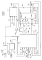
figure 1 représente un synoptique modulaire d'un dispositif pour la mise en oeuvre du procédé suivant l'invention, - la
figure 2 est une vue schématique de dessus d'un véhicule, sur lequel est mis en oeuvre le procédé suivant l'invention, - la
figure 3 est un synoptique modulaire d'un dispositif pour calculer une dérivée de glissement, utilisée dans le procédé suivant l'invention, - les
figures 4 représentent un mode de réalisation d'un moyen de génération d'un indicateur de glissement,et 5 - les
figures 6 à 8 représentent un mode de réalisation d'un moyen de réhabilitation de l'indicateur de glissement, - la
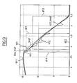
figure 9 représente un chronogramme de différents signaux apparaissant dans le dispositif en ordonnée, en fonction du temps en abscisse.
- the
figure 1 represents a modular block diagram of a device for implementing the method according to the invention, - the
figure 2 is a schematic view from above of a vehicle, on which is implemented the method according to the invention, - the
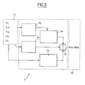
figure 3 is a modular block diagram of a device for calculating a slip derivative, used in the method according to the invention, - the
Figures 4 and 5 represent an embodiment of a means for generating a slip indicator, - the
Figures 6 to 8 represent an embodiment of a means of rehabilitation of the sliding indicator, - the
figure 9 represents a chronogram of different signals appearing in the device on the ordinate, as a function of time on the abscissa.
L'invention est décrite ci-dessous pour un véhicule automobile roulant sur deux roues avant et deux roues arrière, les deux roues avant étant par exemple motrices, les deux roues arrière pouvant éventuellement également être motrices. Sur chaque roue est prévu un capteur 1 de vitesse de rotation, apte à fournir en sortie une mesure W de vitesse de rotation de la roue associée.The invention is described below for a motor vehicle rolling on two front wheels and two rear wheels, the two front wheels being for example driving, the two rear wheels possibly also being driving. On each wheel is provided a
Dans ce qui suit, chacune des quatre roues du véhicule, ainsi que les grandeurs associées à cette roue R, sont désignées par un couple d'indice ij selon la convention suivante :
- 11 ou fl désigne la roue avant gauche,
- 12 ou fr désigne la roue avant droite,
- 21 ou rl désigne la roue arrière gauche,
- 22 ou rr désigne la roue arrière droite.
- 11 or fl designates the left front wheel,
- 12 or fr denotes the right front wheel,
- 21 or rl denotes the left rear wheel,
- 22 or RR stands for the right rear wheel.
Le sens longitudinal s'entend dans le sens avant-arrière.The longitudinal direction is in the front-to-back direction.
Le procédé suivant l'invention est mis en oeuvre dans un dispositif, comprenant par exemple un ou plusieurs calculateurs numériques pour effectuer les traitements et calculs.The method according to the invention is implemented in a device, comprising for example one or more digital computers to perform the processing and calculations.
Le dispositif comporte les entrées suivantes :
- les vitesses Wij de rotation des roues ij,
- le ou les couples moteurs (Cmi) sur le ou les essieux de traction du véhicule,
- le couple Cfij de freinage sur chaque roue ij,
- le rapport Clf = CLf_status, Clr = CLr_status de boîte de vitesses,
- un signal Sl d'indication de l'actionnement des freins ou de l'absence de l'actionnement des freins,
- une accélération longitudinale Al.
- the speeds Wij of rotation of the wheels ij,
- the driving torque (s) (Cmi) on the traction axle (s) of the vehicle,
- the braking torque Cfij on each wheel ij,
- the ratio Clf = CLf_status, Clr = CLr_status of gearbox,
- a signal Sl indicating the actuation of the brakes or the absence of the actuation of the brakes,
- a longitudinal acceleration Al.
L'accélération longitudinale Al est fournie par la mesure d'un capteur 2 embarqué sur le véhicule.The longitudinal acceleration Al is provided by measuring a
Le couple Cmi de traction et le rapport Clf, CLr de boîte de vitesses sont fournis par un calculateur moteur non représenté, ainsi que cela est connu de l'homme du métier.The traction torque Cmi and the gear ratio Clf, CLr are supplied by a motor calculator (not shown), as is known to those skilled in the art.
Le couple Cfij de freinage est calculé à partir des pressions Tfij de freinage pour chaque roue, par un estimateur 3 par exemple du type ABS ou ESP.The braking torque Cfij is calculated from the braking pressures Tfij for each wheel, by an
Un module 4 est prévu pour traiter les vitesses Wij de rotation des roues fournies par les capteurs 1, afin de corriger la différence de vitesse entre les roues dans les virages. Ce module 4 calcule pour chaque roue la vitesse ramenée au centre de l'essieu arrière constituant un centre CR de rotation pour des roues directrices situées à l'avant, ainsi que cela est représenté à la 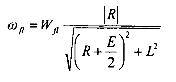


- ω ij :
- Vitesse roue ij centrée
- ψ :
- Vitesse de lacet
- R :
- Rayon du virage
- L :
- Empattement du véhicule
- Wij :
- Information vitesse roue issue du capteur
- E :
- Voie du véhicule
- r :
- Rayon roue
- ω ij :
- Wheel speed ij centered
- ψ:
- Yaw rate
- R :
- Turn radius
- L :
- Wheelbase of the vehicle
- W ij :
- Wheel speed information from the sensor
- E :
- Vehicle lane
- r :
- Wheel radius
Le rayon R du virage est calculé à partir de la vitesse de lacet et de l'angle α de braquage des roues, c'est-à-dire αd pour la roue avant droite et αg pour la roue avant gauche. Cet angle αd, αg de volant et la vitesse de lacet sont mesurés par des capteurs embarqués sur le véhicule.The radius R of the turn is calculated from the yaw rate and the steering angle α of the wheels, that is to say α d for the right front wheel and αg for the left front wheel. This steering wheel angle α d , α g and the yaw rate are measured by onboard sensors on the vehicle.
Les vitesses ωij qui sont utilisées par la suite ont par exemple été filtrées par un filtre passe-bas.The speeds ω ij which are used subsequently have for example been filtered by a low-pass filter.
Un estimateur 7 est prévu pour calculer une dérivée dSxij du glissement de la roue ij à partir de la vitesse de rotation ωij de la roue, des couples moteurs Cmi , des couples de freinage Cfij (ou des pressions de freinage Tfij), du rapport de boîte de vitesses engagées CLf, CLr, qui forment des entrées reçues sur un bloc 71 d'entrée de l'estimateur 7.An
Un mode de réalisation de cet estimateur 7 est décrit ci-dessous en référence à la
Le bloc 72 effectue une dérivation discrète et un filtrage de la vitesse de chaque roue et fournit une estimation de l'accélération de chaque roue.
Le bloc 73 effectue une estimation de la valeur du couple appliqué à chaque roue en tenant compte de la pression de freinage, du rapport de boîte de vitesses engagé et de l'état de l'embrayage.
Le bloc 75 effectue une estimation de l'inertie des roues pour chacun des essieux avant et arrière du véhicule.
Le bloc 74 qui est relié au bloc 72 effectue une transformation géométrique de l'estimation de l'accélération de chaque roue effectuée par le bloc 72.
Le bloc 76 effectue l'estimation de la dérivée du glissement de chaque roue, à partir des valeurs estimées par les blocs 74, 75 et 73.The
On détaillera ci-après les calculs effectués par chacun des blocs ci-dessus.The calculations made by each of the blocks above will be detailed below.
On notera également Jij l'inertie équivalente à la roue, r le rayon de la roue, N le rapport de réduction globale, Tmj le couple moteur sur les essieux du véhicule (i=f, r pour représenter le couple moteur à l'essieu avant (front) ou arrière (rear) du véhicule), Pij les pressions de frein à la roue (i=f, r et j=d, g pour représenter une roue droite ou gauche du véhicule), Fij les efforts extérieurs appliqués à la roue, M la masse du véhicule, et V la vitesse du véhicule.We also note Jij the inertia equivalent to the wheel, r the radius of the wheel, N the overall reduction ratio, Tm j the engine torque on the axles of the vehicle (i = f, r to represent the engine torque to the front (front) or rear (rear) axle of the vehicle), P ij the wheel brake pressures (i = f, r and j = d, g to represent a right or left wheel of the vehicle), F ij the forces applied to the wheel, M the mass of the vehicle, and V the speed of the vehicle.
Dans le bloc 72, l'accélération de chaque roue est obtenue par dérivation discrète et filtrage de la vitesse de roue.In
Dans le bloc 73, le couple moteur appliqué à chaque roue peut être obtenu à partir des informations issues des actionneurs ou par estimation.In
Pour un actionneur électrique, le couple fourni est bien maîtrisé et peut être estimé grâce aux mesures de courant électrique et de régime moteur. Pour un moteur thermique, une estimation du couple moteur donne une information sur le couple fourni avec un degré de précision moyen mais suffisant.For an electric actuator, the torque supplied is well controlled and can be estimated thanks to the measurements of electric current and engine speed. For a heat engine, an estimate of the engine torque gives information on the torque supplied with a medium but sufficient degree of precision.
Ensuite, le couple à chaque roue est calculé en prenant en considération le rapport de boîte ou l'état des embrayages (ou crabot) entre l'actionneur et les roues. Le différentiel est modélisé simplement mais il est envisageable d'améliorer le calcul du couple à la roue en utilisant un modèle de différentiel plus sophistiqué.Then, the torque at each wheel is calculated taking into consideration the gear ratio or the condition of the clutches (or clutch) between the actuator and the wheels. The differential is modeled simply but it is possible to improve the calculation of the torque to the wheel by using a more sophisticated differential model.
Dans la suite Cmij représente le couple moteur à la roue (i=f, r pour représenter le couple moteur à l'essieu avant ou arrière du véhicule, j=r, l pour représenter une roue droite ou gauche du véhicule), Pfij les pressions de frein à la roue (i, j décrit précédemment) et Cfij les couples de frein correspondant.In the following Cm ij represents the engine torque at the wheel (i = f, r to represent the engine torque at the front or rear axle of the vehicle, j = r, l to represent a right or left wheel of the vehicle), Pf ij the pressures brake on the wheel (i, j described above) and Cf ij the corresponding brake torques.
Une illustration de l'invention consiste à calculer le couple à la roue grâce à l'expression suivante (différentiel parfait).An illustration of the invention consists in calculating the torque at the wheel thanks to the following expression (perfect differential).
Pour le couple aux roues avant droit et gauche : ![]()
![]()
![]()
![]()
![]()
![]()
![]()
![]()
Pour le couple aux roues arrières droite et gauche : ![]()
![]()
![]()
![]()
![]()
![]()
![]()
![]()
« Efficacité_Arrière et Efficacité_Avant» désignent les efficacités des freins (grandeur connue et identifiée par ailleurs) et Cli_status (i=f, r pour front, rear) le rapport engagé, cette valeur étant égale à 0, lorsque l'embrayage est ouvert."Efficiency_Rear and Efficiency_Avant" denote the efficiencies of the brakes (quantity known and identified elsewhere) and Cli_status (i = f, r for front, rear) the engaged ratio, this value being equal to 0, when the clutch is open.
Des variantes sont possibles pour améliorer l'estimation des couples moteurs et freins notamment pour :
- prendre en compte les variations de l'efficacité des freins à l'aide de techniques d'observations et
- mieux représenter le différentiel.
- take into account variations in brake efficiency using observation techniques and
- better represent the differential.
Le bloc 75 estime l'inertie des roues d'un même essieu, par exemple Jfi pour l'essieu avant cette inertie est fonction de l'inertie moteur Jmot et de l'inertie pont+roue Jpont selon l'équation suivante : 
avec CLi_status (f, r pour front, rear) le rapport engagé (0 si l'embrayage est ouvert).with CLi_status (f, r for front, rear) the gear engaged (0 if the clutch is open).
Le bloc 74 effectue une transformation géométrique.
Dans le contexte d'un véhicule à 2 ou 4 roues motrices, les équations suivantes sont vérifiées pour chaque roue du véhicule : 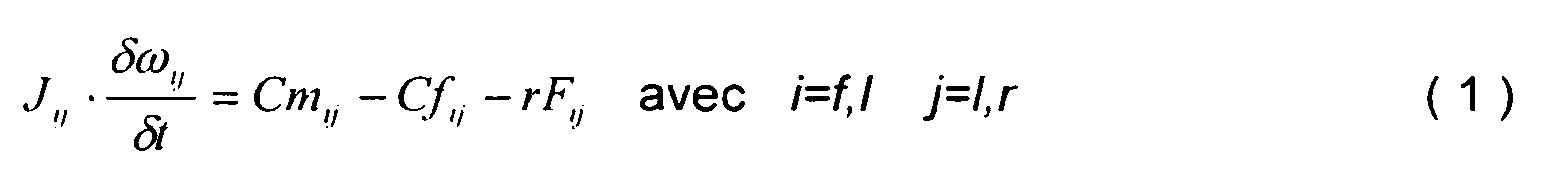

On supposera que la contribution de la force aérodynamique (- CxV2) est négligeable dans le calcul de la dynamique de glissement. De ce fait le terme aérodynamique disparaît dans la suite du calcul.It will be assumed that the contribution of the aerodynamic force (- C x V 2 ) is negligible in the calculation of the sliding dynamics. As a result, the aerodynamic term disappears in the rest of the calculation.
On appelle Sxij le glissement de la roue ij défini de la façon suivante : ![]()
![]()
En multipliant les deux termes de l'équation (2) par le rayon de la roue r et en sommant terme à terme l'équation ainsi obtenue avec l'équation (1), on obtient l'équation suivante : 
En dérivant par rapport au temps t les deux termes de l'équation (3) on obtient : 
On peut maintenant remplacer le terme ![]()

![]()
L'estimation de la dérivée du glissement pour chacune des quatre roues est alors donnée par : 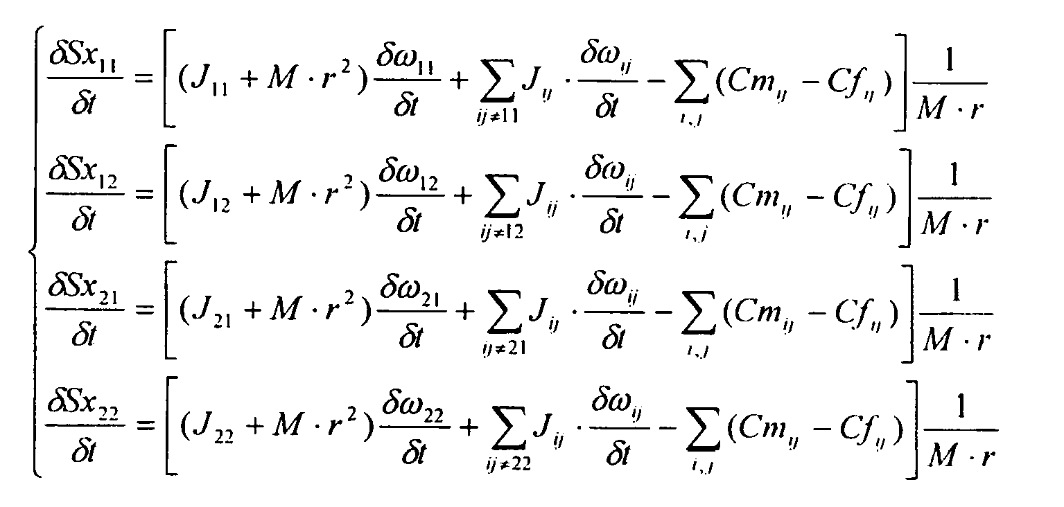
On note dans cette expression que le calcul de la dérivée du glissement est exact, difiérente pour une roue droite et une roue gauche et ne dépend plus des efforts extérieurs.We note in this expression that the calculation of the derivative of the slip is exact, difierent for a right wheel and a left wheel and no longer depends on external forces.
La sortie du système (bloc 77) est notée 
Les essais ont montré qu'il existait un écart très faible entre la valeur calculée de la dérivée du glissement et la valeur réelle de cette dérivée.The tests showed that there was a very small difference between the calculated value of the slip derivative and the actual value of this derivative.
Ainsi, l'unité de calcul selon l'invention peut être utilisée pour contrôler de façon très précise notamment un dispositif d'anti-blocage des roues et/ou un dispositif d'anti-patinage des roues d'un véhicule automobile.Thus, the computing unit according to the invention can be used to very precisely control including a wheel anti-lock device and / or an anti-skid device of the wheels of a motor vehicle.
L'estimateur 7 met ainsi en oeuvre un procédé pour estimer la dérivée du glissement des roues d'un véhicule automobile équipé de deux ou quatre roues motrices et d'une unité de calcul pour mettre en oeuvre ce procédé, comprenant les étapes suivantes :
- a) la saisie de données sur la vitesse des roues, des couples moteurs appliqués sur les roues, des pressions de freinage, du rapport de boîte de vitesses engagé,
- b) l'estimation de l'accélération de chaque roue en effectuant une dérivation discrète et un filtrage de la vitesse de chaque roue,
- c) l'estimation du couple appliqué à chaque roue en tenant compte, de la pression de freinage, du rapport de boîte de vitesses engagé et de l'état de l'embrayage,
- d) l'estimation de l'inertie des roues pour chacun des essieux avant et arrière du véhicule,
- e) la mise en oeuvre d'une transformation géométrique de l'estimation de l'accélération de chaque roue estimée en b),
- f) l'estimation de la dérivée du glissement de chaque roue, à partir des valeurs estimées en c), d) et e).
- (a) capturing data on wheel speed, engine torque applied to the wheels, braking pressures, engaged gear ratio,
- b) estimating the acceleration of each wheel by performing a discrete bypass and filtering the speed of each wheel,
- c) the estimation of the torque applied to each wheel, taking into account the braking pressure, the engaged gear ratio and the condition of the clutch,
- (d) the estimated wheel inertia for each of the front and rear axles of the vehicle,
- e) the implementation of a geometric transformation of the estimation of the acceleration of each wheel estimated in b),
- f) the estimation of the slip derivative of each wheel, from the values estimated in c), d) and e).
Un module 8 est prévu pour déterminer un mode de calcul de la vitesse longitudinale du véhicule pour fournir sur une sortie un signal MOD d'indication de mode de calcul.A
Ce module 8 comporte les entrées suivantes :
- C ml = Tmot_AV : Couple fourni par le moteur avant (Cml pour i = 1 à l'avant) ;
- Cm2 = Tmot_AR : Couple fournir par le moteur arrière (Cml pour i = 2 à l'arrière) ;
- Sl = Freinconducteur : ce signal est obtenu de la façon suivante :
- 1 si le conducteur appuie sur la pédale de frein
- 0 sinon ;
- Sl2 = FreinESP_AV : ce signal est obtenu de la façon suivante :
- 1 si au moins une roue avant est freinée par une régulation du type ABS/ASR/ESP
- 0 sinon ;
- Sl3 = FreinESP_AR : Ce signal est obtenu de la façon suivante :
- 1 si au moins une roue arrière est freinée par une régulation du type ABS/ASR/ESP
- 0 sinon.
- C m l = T mot_AV : Torque supplied by the front engine ( C ml for i = 1 at the front);
- C m2 = T mot_AR : Torque supplied by the rear engine ( C ml for i = 2 at the rear);
- Sl = Driver brake : this signal is obtained as follows:
- 1 if the driver depresses the brake pedal
- 0 otherwise;
- Sl2 = Brake ESP_AV : this signal is obtained in the following way:
- 1 if at least one front wheel is braked by a regulation of the ABS / ASR / ESP type
- 0 otherwise;
- Sl3 = Brake ESP_AR : This signal is obtained in the following way:
- 1 if at least one rear wheel is braked by a regulation of the ABS / ASR / ESP type
- 0 otherwise.
Un module 5 représente globalement l'entité fournissant Sl, Sl1, Sl2.A
Le moteur avant est le moteur entraînant les roues avant. Dans le cas où les roues arrière sont entraînées par un moteur et où les roues avant ne sont pas entraînées, Tmot_AV = 0.The front engine is the engine driving the front wheels. In the case where the rear wheels are driven by a motor and where the front wheels are not driven, T mot_AV = 0.
Le moteur arrière est le moteur entraînant les roues arrière. Dans le cas où les roues avant sont entraînées par un moteur et où les roues arrière ne sont pas entraînées, Tmot_AR = 0.The rear engine is the engine driving the rear wheels. In the case where the front wheels are driven by a motor and where the rear wheels are not driven, T mot_AR = 0.
Dans le cas où à la fois les roues avant et les roues arrière sont entraînées par un même moteur ou par deux moteurs différents, Tmot_AV et Tmot_AR sont pris en compte, comme par exemple dans le cas d'un véhicule 4x4.In the case where both the front wheels and the rear wheels are driven by the same motor or by two different engines, T mot_AV and T mot_AR are taken into account, as for example in the case of a 4x4 vehicle.
Dans un mode de réalisation, le signal MOD de mode de calcul de la vitesse longitudinale prend l'un parmi trois états 1, 2, 3, de la manière suivante :
- MOD = 2 Sl

- MOD = 3 Sl
- MOD = 1 SINON.
- MOD = 2 Sl
- MOD = 3 Sl
- MOD = 1 ELSE.
En outre, en cas de glissement Sx négatif en situation de freinage du conducteur, MOD = 4 et Vest sera obtenue à partir du maximum des vitesses ωij des roues, multiplié par un rayon de roue.In addition, in case of slip Sx negative braking situation of the driver, MOD = 4 and Vest will be obtained from the maximum velocities ω ij wheels, multiplied by a wheel radius.
En outre, en cas de glissement Sx positif en situation de non freinage du conducteur en traction, MOD = 5 et Vest sera obtenue à partir du minimum des vitesses ωij des roues, multiplié par un rayon de roue.In addition, in the case of positive slip Sx in a non-braking situation of the driver in traction, MOD = 5 and Vest will be obtained from the minimum speed ω ij of the wheels, multiplied by a wheel radius.
Seuilmot_AV et Seuilmot_AR représentent des valeurs seuils sur les couples moteurs avant et arrière. Ils peuvent être choisis de la façon suivante :
- on se fixe une valeur d'adhérence µ min ,
- on suppose que le poids du véhicule Fz_tot est réparti de façon fixe sur les essieux avant et arrière :

- we set a bond value μ min ,
- it is assumed that the weight of the vehicle F z_tot is distributed in a fixed manner on the front and rear axles:
On peut poser par exemple x = 2/3.One can ask, for example x = 2/3.
Les seuils Seuilmot_AV et Seuilmot_AR sont alors fixés de la façon suivante : 
Les seuils Seuilmot_AV et Seuilmot_AV ainsi choisis représentent donc les couples moteurs minima (avant ou arrière) pour un coefficient d'adhérence µmin.Thresholds Threshold word_AV and Threshold word_AV thus chosen represent the minimum motor torques (front or rear) for a coefficient of adhesion μ min .
Avec cette méthode, le choix des seuils Seui/ mot_AV et Seuilmot_AR revient à choisir la valeur de µmin. Pour une adhérence supérieure ou égale à µmin, un couple moteur (avant ou arrière) inférieur à Seuilmot_AV ou Seuilmot_AV est insuffisant pour faire glisser les roues.With this method, the choice of thresholds Seui / mot_AV and Threshold word_AR is to choose the value of μ min . For greater than or equal adhesion μ min, an engine torque (front or back) of less than or mot_AV Threshold Threshold mot_AV is insufficient to drag the wheels.
Un estimateur 9 calcule une vitesse longitudinale estimée V=Vest du véhicule, également appelée vitesse de référence. La vitesse Vest est générée sur une sortie 6 de l'estimateur 9 et est en outre envoyé à une entrée 12 d'un estimateur 10.An
Le principe de base de calcul de la vitesse de référence Vest est d'utiliser l'information des vitesses des roues qui ne glissent pas.The basic principle of calculating the reference speed Vest is to use the information of the speeds of the wheels that do not slip.
Cet estimateur 9 comporte les entrées suivantes :
une entrée 22 pour le signal MOD de mode de calcul issu dumodule 8,- des entrées 23 pour les vitesses de rotation ω ij des roues,
- pour les différentes roues ij, des entrées 24 pour l'indicateur dij de glissement de la roue ij, qui prend un premier état dij = 1 de glissement si la roue est glissante, par exemple dans le cas d'un patinage ou d'un blocage, ou un deuxième état dij = 0 d'absence de glissement de la roue ij si l'état de la roue est normal, c'est-à-dire si sa vitesse est cohérente avec la vitesse du véhicule,
une entrée 20 pour un signal UTACC d'utilisation d'accélération,une entrée 21 pour l'accélération AL issue du capteur 2.
- an
input 22 for the calculation mode signal MOD frommodule 8, -
inputs 23 for the rotational speeds ω ij of the wheels, - for the different wheels ij,
inputs 24 for the dij sliding indicator of the wheel ij, which takes a first state dij = 1 slip if the wheel is slippery, for example in the case of a skate or a blocking, or a second state dij = 0 of no slip of the wheel ij if the state of the wheel is normal, that is to say if its speed is consistent with the speed of the vehicle, - an
input 20 for a UTACC acceleration utilization signal, - an
input 21 for the acceleration AL from thesensor 2.
Le signal Vest est obtenu de la façon suivante :
- . Sl MOD = 1 alors

- . Sl MOD = 2 alors

- Sl MOD = 3 alors

- . Sl MOD = 1 then
- . Sl MOD = 2 then
- Sl MOD = 3 then
Les considérations qui sont à la base de cette estimation sont les suivantes :
- 1. Les roues soumises à un faible couple (le signal MOD contient cette information) sont les mieux adaptées à estimer la vitesse longitudinale du véhicule. On appelle ici "faible couple" un couple insuffisant à faire glisser les roues si l'adhérence est supérieure à la valeur µmin choisie. Si par exemple le couple à l'essieu arrière du véhicule est nul (véhicule en mode traction avant) et que le conducteur du véhicule ne freine pas et qu'il n'y a pas d'intervention des systèmes actifs de sécurité alors MOD = 3 et on utilisera de préférence les vitesses des roues arrière pour estimer la vitesse de référence.
- 2. Les roues caractérisées par un dij = 1 (roues estimées glissantes) ne doivent pas être utilisés pour l'estimation ;
- 3. Une moyenne arithmétique des vitesses des roues préconisées au
point 1. et autorisées aupoint 2. fournit la meilleure estimation de la vitesse longitudinale du véhicule : - 4. Si les 4 roues glissent, on ne peut pas estimer la vitesse longitudinale du véhicule avec l'information de vitesse roues ωij.
- 1. Wheels subjected to a low torque (the MOD signal contains this information) are best suited to estimate the longitudinal speed of the vehicle. We call here "low torque" insufficient torque to slide the wheels if the adhesion is greater than the value μ min chosen. If for example the torque at the rear axle of the vehicle is zero (vehicle in front-wheel drive mode) and the driver of the vehicle does not brake and there is no intervention of the active safety systems then MOD = 3 and it will be preferable to use the speeds of the rear wheels to estimate the speed of reference.
- 2. Wheels characterized by a dij = 1 (estimated sliding wheels) shall not be used for the estimation;
- 3. An arithmetic average of the wheel speeds recommended in
point 1. and authorized inpoint 2. provides the best estimate of the longitudinal speed of the vehicle: - 4. If the 4 wheels slip, the longitudinal speed of the vehicle can not be estimated with wheel speed information ωij.
Le fait que toutes les roues glissent est détecté par le fait qu'un signal UTACC d'utilisation d'accélération est dans un premier état d'utilisation d'accélération. Dans ce cas, la vitesse longitudinale Vest sera estimée en intégrant l'accélération longitudinale Al, des moyens étant prévus à cet effet dans l'estimateur 9.The fact that all the wheels are sliding is detected by the fact that an acceleration utilization UTACC signal is in a first state of use of acceleration. In this case, the longitudinal speed Vest will be estimated by integrating the longitudinal acceleration Al, means being provided for this purpose in the
Un moyen est également prévu, par exemple dans l'estimateur 9, pour fournir sur une sortie 19 un signal FIAB d'indication de fiabilité de la valeur Vest de vitesse longitudinale et du glissement Sxij des roues.A means is also provided, for example in the
Dans un mode de réalisation, ce signal FIAB est binaire et obtenu de la façon suivante : 
le signal fiabilité ne peut prendre alors que deux valeurs :
- 0 : Vest. n'est pas fiable, donc les quatre roues sont considérées glissantes (dij = 1 pour toutes les roues),
- 1 : Vest est fiable, donc au moins une roue ne glisse pas.
the signal reliability can only take two values:
- 0: V is. is not reliable, so the four wheels are considered slippery (dij = 1 for all the wheels),
- 1: V is reliable, so at least one wheel does not slip.
Un autre mode de réalisation est le suivant : 
Le signal fiabilité peut prendre alors trois valeurs :
- 0 : Vest n'est pas fiable, donc les quatre roues sont considérées glissantes (dij = 1 ∀ ij ).
- 2 : Vest , est "très" fiable, donc les quatre roues ne glissent pas ou les deux roues d'un même essieu sont soumises à un faible couple et ne glissent pas.
- 1 : Vest, est "assez" fiable.
- 0: V is not reliable, so the four wheels are considered slippery ( d ij = 1 ∀ ij ).
- 2: V is , is "very" reliable, so the four wheels do not slip or the two wheels of the same axle are subject to a low torque and do not slip.
- 1: V is , is "pretty" reliable.
Dans un mode de réalisation, il est prévu, par exemple dans l'estimateur 9, un moyen pour calculer un signal NF d'indication de non fiabilité des glissements Sxij des roues en fonction des indicateurs dij de glissement des roues ij de la manière suivante :
- NF = 1 (1 étant un état d'absence de fiabilité) si pour toutes les roues, dij = 1, correspondant au fait que toutes les roues glissent,
- NF = 0 sinon, correspondant à un deuxième état de présence de fiabilité.
- NF = 1 (1 being a state of unreliability) if for all the wheels, dij = 1, corresponding to the fact that all the wheels slip,
- NF = 0 otherwise, corresponding to a second state of presence of reliability.
Le signal NF prend l'état 1 d'absence de fiabilité lorsque l'on ne veut pas prendre en compte le signal Sxij pour détecter le glissement d'une roue.The signal NF takes the
Un estimateur 10 est prévu pour calculer les indicateurs dij de glissement des roues ij. L'estimateur 10 comporte les entrées suivantes :
- la dérivée dSxij de glissement des roues ij,
- la vitesse longitudinale estimée Vest, également appelée vitesse de référence Vest,
- le signal NF d'absence de fiabilité.
- the derivative dSxij of sliding wheels ij,
- the estimated longitudinal velocity V is , also called the reference speed Vest,
- the NF signal of unreliability.
Un moyen 11 est prévu, par exemple dans l'estimateur 10, pour calculer le glissement absolu Sxij de la roue ij suivant la formule : ![]()
avec ![]()
- Vest et ωij étant en entrées 12, 13 du
module 11, Sxij étant en sortie 14 du moyen 11. - Vroue ij représente la vitesse linéaire de la roue ij.
with
- Vest and ωij being in
inputs module 11, Sxij being at theoutput 14 of themeans 11. - V wheel ij represents the linear speed of the wheel ij.
Dans le module 10, la dérivée dSxij de glissement est éventuellement filtrée dans un filtre passe-bande. Le signal issu de ce filtrage passe-bande étant ensuite utilisé.In the
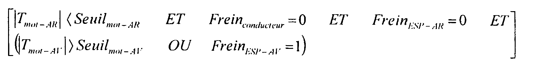
Dans le cas où le signal NF est dans l'état NF = 0 de présence de fiabilité, l'indicateur dij de glissement de roue est mis dans le premier état dij=1 de glissement lorsque les conditions suivantes sont remplies : ![]()
![]()
Dans le cas où le signal NF se trouve dans l'état NF = 1 d'absence de fiabilité, l'indicateur dij de glissement est mis dans l'état de glissement dij = 1, lorsque les conditions suivantes sont remplies : ![]()
- dS1 est un seuil positif de détection de glissement pour dSx (un premier seuil positif pour les valeurs positives de dSxij et un deuxième seuil négatif pour les valeurs négatives de dSxij pourrait également être prévu),
- S2 est un troisième seuil positif de glissement,
- S3 est un quatrième seuil négatif de glissement,
- dS4 est un seuil positif de dérivée de glissement (un premier seuil positif pour les valeurs positives de dSxij et un deuxième seuil négatif pour les valeurs négatives de dSxij pourrait également être prévu).
- dS1 is a positive slip detection threshold for dSx (a positive first threshold for positive values of dSxij and a second negative threshold for negative values of dSxij could also be expected),
- S2 is a third positive slip threshold,
- S3 is a fourth negative slip threshold,
- dS4 is a slip derivative positive threshold (a positive first threshold for positive values of dSxij and a second negative threshold for negative values of dSxij could also be expected).
Les seuils dS1, S2, S3, dS4 sont prescrits à des valeurs constantes dans le module 10.The thresholds dS1, S2, S3, dS4 are prescribed at constant values in the
On décrit ci-dessous en référence aux
La dérivé dSxij de glissement est envoyée à l'entrée d'un moyen 101 de formation du module, dont la sortie est reliée à une première entrée 102 d'un comparateur 103, dont la deuxième entrée 104 est reliée au premier seuil dS1. Le comparateur 103 fournit sur sa sortie 105 un signal DG1 de détection de glissement prenant le premier état 1 de glissement dans le cas où le module de dSxij est supérieur à dS1 et le deuxième état 0 d'absence de glissement sinon.The drift derivative dSxij is sent to the input of a module forming means 101 whose output is connected to a
Dans ce mode de réalisation, dS1 = dS4.In this embodiment, dS1 = dS4.
Un moyen 107 de commutation est prévu, comportant une entrée 110 de commande de commutation reliée au signal NF, pour commuter la sortie 111 de fourniture d'indicateur dij, soit sur une première entrée 108 reliée à la sortie 105 lorsque le signal NF est égal à 1, soit sur une deuxième entrée 109 lorsque le signal NF est égal à 0. L'entrée 109 est reliée à la sortie d'un opérateur logique OU 112, comportant une première entrée 113 reliée à la sortie 105, une deuxième entrée 114 reliée à la sortie d'un comparateur 116 et une troisième entrée 115 reliée à la sortie d'un comparateur 117.A switching means 107 is provided, comprising a switching
Le comparateur 116 comporte une première entrée 118 reliée au signal Sxij de glissement et une deuxième entrée 119 reliée au seuil S2, pour fournir sur sa sortie 114 un état 1 de glissement lorsque le signal sur sa première entrée 118 est supérieur au signal sur sa deuxième entrée 119, et un état 0 d'absence de glissement sinon.The
Le comparateur 117 comporte une première entrée 120 reliée au signal Sxij de glissement et une deuxième entrée 121 reliée au seuil S3, pour fournir sur sa sortie 115 un état 1 de glissement lorsque le signal sur sa première entrée 120 est supérieure au signal sur sa deuxième entrée 121, et un état 0 d'absence de glissement sinon.The
Pour la réhabilitation d'une roue, on utilise les signaux Sxij et dSxij utilisés pour la détection de glissement. La grandeur dSxij est par exemple filtrée dans un filtre passe-bas. On définit en entrée le signal logique Sl de freinage du conducteur, qui prend la valeur 1 de freinage lorsqu'on est en situation de freinage et prend la valeur 0 sinon.For the rehabilitation of a wheel, the signals Sxij and dSxij used for the slip detection are used. The size dSxij is for example filtered in a low-pass filter. The logic signal Sl of the braking of the driver is defined as input, which takes the
On décrit ci-dessous des moyens de réhabilitation d'une roue pour faire passer l'indicateur dij de l'état 1 de glissement à l'état 0 d'absence de glissement lorsque certaines conditions sont respectées. On définit à partir des indicateurs dij dans leur état actuel un signal UTACC d'utilisation d'accélération pour le calcul de l'état suivant des indicateurs dij. Ce signal UTACC d'utilisation d'accélération est par exemple calculé par un module 17, par exemple de l'estimateur 10, comportant en entrées les indicateurs dij des roues, issus du module 15, et en sortie 18 le signal UTACC.The following is a description of means for rehabilitating a wheel in order to change the indicator dij from the
Lorsque pour toutes les roues, les indicateurs dij sont dans l'état 1 de glissement, le signal UTACC prend la valeur 1, ou sinon prend la valeur 0.When for all the wheels, the indicators dij are in the
Dans le cas particulier où toutes les roues glissent et que le signal UTACC d'utilisation est à 1, la vitesse de référence est estimée dans le module 9 en intégrant la valeur d'accélération longitudinale Al fournie par le capteur 2, le module 9 comportant à cet effet un module intégrateur recevant cette accélération longitudinale Al.In the particular case where all the wheels slip and the use UTACC signal is at 1, the reference speed is estimated in the
Dans le cas où le signal UTACC est dans l'état 0 de non utilisation de l'accélération, l'indicateur dij est réhabilité dans l'état 0 d'absence de glissement de la manière suivante. ![]()
alors dij=0.
Si ![]()
et ![]()
alors dij=0.In the case where the UTACC signal is in the ![]()
then dij = 0.
Yes ![]()
and ![]()
then dij = 0.
Dans le cas où le signal UTACC est dans l'état 1 d'utilisation de l'accélération, l'indicateur dij est réhabilité dans l'état 0 d'absence de glissement de la manière suivante : ![]()
![]()
- dS12 est un seuil positif prescrit de réhabilitation pour la dérivée de glissement,
- T121 est une durée prescrite pendant laquelle la valeur absolue du signal dSxj doit se trouver en dessous du seuil dS12. Cette temporisation peut être différente dans le cas d'un glissement négatif ou positif. Dans le cas d'un freinage, correspondant à un glissement négatif, une durée prescrite différente T122 est définie.
- S11 est un seuil positif prescrit de réhabilitation pour le glissement, dans le cas d'un freinage du conducteur,
- T11 est une durée prescrite pendant laquelle la valeur absolue du signal Sxij doit se trouver en-dessous du seuil S11,
- S13 est un seuil positif prescrit de réhabilitation pour le glissement Sx, dans le cas où il n'y a pas de freinage du conducteur.
- dS12 is a prescribed positive threshold of rehabilitation for the slip derivative,
- T121 is a prescribed duration during which the absolute value of the signal dSxj must be below the threshold dS12. This time delay may be different in the case of a negative or positive slip. In the case of braking, corresponding to a negative slip, a different prescribed time T122 is defined.
- S11 is a prescribed positive threshold of rehabilitation for sliding, in the case of driver braking,
- T11 is a prescribed time during which the absolute value of the signal Sxij must be below the threshold S11,
- S13 is a prescribed positive threshold of rehabilitation for slip Sx, in the case where there is no braking of the driver.
Comme précédemment, chaque seuil sur les modules ou valeurs absolues peut comprendre un seuil positif pour les valeurs positives et un seuil négatif pour les valeurs négatives.As before, each threshold on the modules or absolute values may include a positive threshold for the positive values and a negative threshold for the negative values.
On décrit ci-dessous en référence aux
Le moyen 200 de réhabilitation comporte un commutateur 201 comportant une sortie 202 de fourniture de l'indicateur dij = 0 de fin de glissement, et une entrée 203 de commande de commutation reliée au signal UTACC d'utilisation d'accélération pour commuter la sortie 202, soit sur une première entrée 204 dans le cas où l'accélération est utilisée (UTACC = 1), soit sur une deuxième entrée 205 dans le cas où l'accélération n'est pas utilisée (UTACC = 0). L'entrée 205 est reliée à la sortie d'un commutateur 206 comportant une entrée 207 de commande de commutation reliée au signal Sl de freinage pour commuter l'entrée 205, soit sur une première entrée 208 du commutateur 206 dans le cas où le signal SL est à 1 en présence d'un freinage du conducteur, soit sur une deuxième entrée 209 du commutateur 206 dans le cas où le signal SL est à 0 en l'absence de freinage du conducteur. L'entrée 208 est reliée à un signal RV de réhabilitation sur la vitesse. L'entrée 209 est reliée à la sortie d'un opérateur logique ET 210, comportant une première entrée 211 reliée à la sortie Q d'état d'une bascule 213 de type RS et une deuxième entrée 212 reliée à la sortie d'un comparateur 214. La bascule 213 est à l'état initial Q0=0 et comporte une entrée 215 de réinitialisation reliée à la sortie 111 de détection de glissement et une entrée S 216 de réglage. Le comparateur 214 comporte une première entrée 217 reliée à la sortie d'un opérateur 218 formant la valeur absolue du signal Sxij de glissement appliqué sur son entrée 14 et une deuxième entrée 219 reliée au seuil S13. Les entrées 204 et 216 sont reliées à un signal COND de condition de réhabilitation sur dSxij. La sortie du comparateur 214 fournit sur l'entrée 212 ainsi que sur une dérivation 220 de celle-ci un signal Sxc d'indication de correction, qui est égal à 1 lorsque la valeur sur l'entrée 217 est inférieure ou égale à la valeur sur l'entrée 219, et qui est égal à 0 sinon.The rehabilitation means 200 comprises a
A la
A la
La
Claims (20)
- Method for estimating a reference speed of a motor vehicle with wheels, with the aid of at least one computer embedded onboard the vehicle, in which the speed (Wij) of rotation of each wheel (ij) of the vehicle is measured by at least one sensor (1), a speed (Vest) of longitudinal displacement of the vehicle being obtained,
characterized in that
for each wheel, the slippage (Sxij) of the wheel is computed on the basis of the speed (Wij) of rotation of the wheel and of the speed (Vest) of longitudinal displacement obtained,
for each wheel, a derivative (dSxij) of slippage of the wheel is computed on the basis at least of the measured wheel rotation speed (Wij) and of at least one other quantity,
a signal (NF) of non-reliability of the slippages of the wheels is computed, taking a first state (NF=1) of absence of reliability in the case where, for all the wheels, a slippage indicator (dij) is in a first slippage state (dij=1), and at least one second state otherwise,- in the case where the signal (NF) of non-reliability is in the second state, for each wheel, the wheel slippage indicator (dij) takes the first slippage state (dij=1) when the derivative (dSxij) of slippage of the wheel is greater than a first prescribed positive threshold (dS1) or when the derivative (dSxij) of slippage of the wheel is less than a second prescribed negative threshold (dS1) or when the slippage (Sxij) of the wheel is greater than a third prescribed positive threshold (S2) or when the slippage (Sxij) of the wheel is less than a fourth prescribed negative threshold (S3), and otherwise takes a second state (dij=0) of absence of slippage of the wheel,- in the case where the signal (NF) of non-reliability is in the first state (NF=1), the wheel slippage indicator (dij) takes the first slippage state (dij=1) when the derivative (Sxij) of slippage of the wheel is greater than a fifth prescribed positive threshold (dS4) or when the derivative (dSxij) of slippage of the wheel is less than a sixth prescribed negative threshold (dS4). - Method of estimation in accordance with Claim 1, characterised in that a braking indication signal (SI), able to be in a first braking state or in a second absence of braking state, is obtained on the basis of at least one driver-operated braking actuation member,
the wheel slippage indicator (dij) is returned from its first slippage state to its second absence of slippage state when at one and the same time the indicators (dij) of slippage of the wheels are not all in the first slippage state (dij = 1), the braking signal (SI) is in the first braking state and the associated slippage (Sxij) is less than a seventh prescribed positive threshold (S11) and greater than an eighth prescribed negative threshold (S11) for a first prescribed duration (T11). - Method of estimation in accordance with any one of the preceding claims, characterised in that a braking indication signal (SI), able to be in a first braking state or in a second absence of braking state, is obtained on the basis of at least one driver-operated braking actuation member,
the wheel slippage indicator (dij) is returned from its first slippage state to its second absence of slippage state when at one and the same time the indicators (dij) of slippage of the wheels are not all in the first slippage state (dij = 1), the braking signal (SI) is in the second absence of braking detection state (SI = 0), the slippage derivative (dSxij) is less than a ninth prescribed positive threshold (dS12) and greater than a tenth prescribed negative threshold (dS12) for a second duration (T121), the slippage (Sxij) is less than an eleventh prescribed positive threshold (S13) and greater than a twelfth prescribed negative threshold (S13) at the end of the said second duration (T121). - Method of estimation in accordance with any one of the preceding claims, characterized in that a braking indication signal (SI), able to be in a first braking state or in a second absence of braking state, is obtained on the basis of at least one driver-operated braking actuation member,
the wheel slippage indicator (dij) is returned from its first slippage state to its second absence of slippage state, when at one and the same time the indicators (dij) of slippage of the wheels are all in the first slippage state (dij = 1), the braking signal (SI) is in the first braking detection state and the slippage derivative (dSxij) is less than a thirteenth prescribed positive threshold (dS12) and greater than a fourteenth prescribed negative threshold (dS12) for third prescribed duration (T122). - Method of estimation in accordance with any one of the preceding claims, characterized in that a braking indication signal (SI), able to be in a first braking state or in a second absence of braking state, is obtained on the basis of at least one driver-operated braking actuation member,
the wheel slippage indicator (dij) is rehabilitated from its first slippage state to its second absence of slippage state when at one and the same time the indicators (dij) of slippage of the wheels are all in the first slippage state, the braking signal (SI) is in the second absence of braking detection state, the slippage derivative (dSxij) is less than a fifteenth prescribed positive threshold (dS12) and greater than a sixteenth prescribed negative threshold (dS12) for a second duration (T121). - Method in accordance with any one of the preceding claims, characterized in that the computation of the slippage derivative (dSxij) comprises the following steps:g) the entry of data relating to the speed of rotation of the wheels, of the motor torques applied to the wheels, of the braking pressures, of the gearbox ratio engaged,h) the estimation of the acceleration of each wheel by performing a discrete differentiation and a filtering of the speed of rotation of each wheel,i) the estimation of the torque applied to each wheel by taking account of the braking pressure, of the gearbox ratio enraged and of the state of the clutch,j) the estimation of the inertia of the wheels for each of the front and rear axles of the vehicle,k) the implementation or a geometric transformation of the estimation of the acceleration of each wheel estimated in b),l) the estimation of the derivative of the slippage of each wheel, on the basis of the values estimated in c), d) and e).
- Method in accordance with any one of the preceding claims, characterized in that the computation of the slippage (Sxij) of the wheel is obtained by multiplying the rotation speed (ωij) of the wheel by its radius delivering the linear speed (Vij) of the wheel, and then by subtracting the said linear speed thus obtained from the speed of longitudinal displacement (Vest) obtained.
- Method in accordance with any one of the preceding claims, characterised in that the speed (Vest) of longitudinal displacement of the vehicle is obtained by computation on the basis of the measured speeds (Wij) of rotation of wheels for which the wheel slippage indicator (dij) is in the second state (dij=0) of absence of slippage of the wheel, without taking account of the measured speeds (Wij) of rotation of wheels for which the wheel slippage indicator (dij) is in the first slippage state (dij=1).
- Method in accordance with any one of the preceding claims, characterized in that in the case where the indicator (dij) of slippage of all the wheels is in the first slippage state (dij=1), the speed (Vest) of longitudinal displacement of the vehicle is obtained by integration of a longitudinal acceleration (Al) measured, by a sensor (2) of longitudinal acceleration.
- Method in accordance with any one of the preceding claims, characterized in that a braking indication signal (SI), able to be in a first braking state or in a second absence of braking state, is obtained on the basis of at least one driver-operated braking actuation member,
when at one and the same time the slippage of a. wheel is negative and the braking indication signal (SI) is the first braking state, the speed (Vest) of longitudinal displacement of the vehicle is obtained on the basis of the maximum of the speeds of rotation of the wheels. - Method in accordance with any one of the preceding claims, characterized in that a braking indication signal (SI), able to be in a first braking state or in a second absence of braking state, is obtained on the basis of at least one driver-operated braking actuation member,
when at one and the same time the slippage of a wheel is positive and the braking indication signal (SI) is in the second absence of braking state, the speed (Vest) of longitudinal displacement of the vehicle is obtained on the basis of the minimum of the speeds of rotation of the wheels. - Method in accordance with any one of the preceding claims, characterized in that
a torque value (Cmi) for the motor (or motors) on the front and/or rear wheels is obtained,
a plurality of modes (MOD) of computation of the speed (Vest) of longitudinal displacement of vehicle are defined:- a first mode of computation (HOD=2), when, at one and the same time the torque on the front wheels is less than a first prescribed positive threshold and greater than a second prescribed negative threshold, the torque on the rear wheels is greater than a third prescribed positive threshold or less than a fourth prescribed negative threshold,- a second mode of computation (MOD=3), when at one and the same time the torque on the rear wheels is less than a fifth prescribed positive threshold and greater than a sixth prescribed negative threshold, the torque on the front wheels is greater than a seventh prescribed positive threshold or less than an eighth prescribed negative threshold,- a third mode of computation (MOD=1), when the conditions corresponding to the first and second modes of computation are not fulfilled. - Method in accordance with Claim 12, characterized in that- in the first mode of computation (MOD=2), the speed (Vest) of longitudinal displacement of the vehicle is computed:• on the basis of the speed of rotation of the front wheels, whose slippage indicator (dij) is in the second absence of slippage state (dij=0), or• if all the front wheels each have their slippage indicator in the first slippage state, on the basis of the speed of rotation of the rear wheels in the second absence of slippage state (dij=0).
- Method in accordance with either one of Claims 12 and 13, characterized in that- in the second mode of computation (MOD=3), the speed (Vest) of longitudinal displacement of the vehicle is computed:• on the basis of the speed of rotation of the rear wheels, whose slippage indicator (dij) is in the second state (dij=0) of absence of slippage, or• if all the rear wheels each have their slippage indicator in the first slippage state, on the basis or the speed of rotation of the front wheels in the second state (dij=0) of absence of slippage.
- Method in accordance with any one of Claims 12 to 14, characterized in that- in the third mode of computation (MOD=1), the speed (Vest) of longitudinal displacement of vehicle is computed on the basis of the speed of rotation of the rear wheels and of the front wheels in the second state (dij=0) of absence of slippage.
- Method in accordance with any one of Claims 12 to 15, characterized in that
a first braking indication signal (SI), able to be in a first braking state or in a second absence of braking state, is obtained on the basis of at least one driver-operated braking actuation member, and
to fulfil the conditions or the first and second modes of computation the first driver braking indication signal (SI) must additionally be in the second absence of braking state. - Method in accordance with any one of Claims 12 to 16, characterized in that
at least one second braking indication signal (SI2) relating to the front wheels, able to be in a first braking state or in a second absence of braking state, and at least one third braking indication signal (SI3) relating to the rear wheels, able to be in a first braking state or in a second absence of braking state, are obtained on the basis of a braking regulation system relating to the front wheels and to the rear wheels,- to fulfil the conditions of the first mode (MOD=2) of computation, at one and the same time the torque on the front wheels is less than a first prescribed positive threshold and greater than a second prescribed negative threshold, the second braking indication signal (SI2) relating to the front wheels is in the second absence of braking state, the torque on the rear wheels is greater than a third prescribed positive threshold or less than a fourth prescribed negative threshold, or the third braking indication signal (SI3) relating to the rear wheels is in the first braking state,- to fulfil the conditions of the second mode (MOD=3) of computation, at one and the same time the torque on the rear wheels is less than a fifth prescribed positive threshold and greater than a sixth prescribed negative threshold, the third braking indication signal (SI3) relating to the rear wheels is in the second absence of braking state, the torque on the front wheels is greater than a seventh prescribed positive threshold or less than an eighth prescribed negative threshold, or the second braking indication signal (SI2) relating to the front wheels is in the first braking state. - Method in accordance with any one or Claims 12 to 17, characterized in that the thresholds are fixed in a manner proportional to a predetermined distribution of weight of the vehicle on at least one front axle supporting the front wheels and on at least one rear axle supporting the rear wheels.
- Method in accordance with any one of Claim 12 to 18, characterized in that to compute the speed (Vest) of longitudinal displacement of the vehicle, the arithmetic average of the wheel rotation speeds employed in the modes of computation is multiplied by a prescribed wheel radius.
- Device for the implementation of the method in accordance with any one of the preceding claims, intended to be embedded onboard a. motor vehicle with wheels, characterized in that it comprises:at least one sensor (1) of the speed (Wij) of rotation of each wheel (ij) of the vehicle,a means (9) for obtaining a speed (Vest) of longitudinal displacement of the vehicle,a means (11) for computing the slippage (Sxij) of each wheel on the basis of the speed (Wij) of rotation of the wheel and of the speed (Vest) of longitudinal displacement obtained,a means (7) for computing, for each wheel, on the basis at least of the measured wheel rotation speed (Wij) and of at least one other quantity, a derivative (dSxij) of slippage of the wheel,a means (9) for computing a signal (NF) of non-reliability of the slippages of the wheels, taking a first state (NF=1) of absence of reliability in the case where, for all the wheels, a slippage indicator (dij) is in a first slippage state (dij=1), and at least one second state otherwise,- a means (15) for generating the indicator (dij) of slippage of each wheel, so that- in the case where the signal (NF) of non-reliability is in the second state, the wheel slippage indicator (dij) takes the first slippage state (dij=1) when the derivative (dSxij) of slippage of the wheel is greater than a first prescribed positive threshold (dS1) or when the derivative (dSxij) of slippage of the wheel is less than a second prescribed negative threshold (dS1) or when the slippage (Sxij) of the wheel is greater than a third prescribed positive threshold (S2) or when the slippage (Sxij) of the wheel is less than a fourth prescribed negative threshold (S3), and otherwise takes a second state (dij=0) of absence of slippage of the wheel,- in the case where the signal (NF) of non-reliability is in the first state (NF=1), the wheel slippage indicator (dij) takes the first slippage state (dij=1) when the derivative (Sxij) of slippage of the wheel is greater than a fifth prescribed positive threshold (dS4) or when the derivative (dSxij) of slippage of the wheel is less than a sixth prescribed negative threshold (dS4).
Applications Claiming Priority (2)
| Application Number | Priority Date | Filing Date | Title |
|---|---|---|---|
| FR0705739A FR2919930B1 (en) | 2007-08-06 | 2007-08-06 | METHOD FOR ESTIMATING THE LONGITUDINAL SPEED OF A VEHICLE AND DEVICE FOR IMPLEMENTING SAID METHOD |
| PCT/FR2008/051371 WO2009019392A2 (en) | 2007-08-06 | 2008-07-21 | Method for estimating the sliding of the wheels of a vehicle and device for implementing same |
Publications (2)
| Publication Number | Publication Date |
|---|---|
| EP2176111A2 EP2176111A2 (en) | 2010-04-21 |
| EP2176111B1 true EP2176111B1 (en) | 2011-09-07 |
Family
ID=39272461
Family Applications (1)
| Application Number | Title | Priority Date | Filing Date |
|---|---|---|---|
| EP08827167A Not-in-force EP2176111B1 (en) | 2007-08-06 | 2008-07-21 | Method for estimating the sliding of the wheels of a vehicle and device for implementing same |
Country Status (4)
| Country | Link |
|---|---|
| EP (1) | EP2176111B1 (en) |
| AT (1) | ATE523404T1 (en) |
| FR (1) | FR2919930B1 (en) |
| WO (1) | WO2009019392A2 (en) |
Cited By (1)
| Publication number | Priority date | Publication date | Assignee | Title |
|---|---|---|---|---|
| EP3900990B1 (en) * | 2018-12-18 | 2024-02-07 | NISSAN MOTOR Co., Ltd. | Vehicle speed estimation method and vehicle speed estimation device for four-wheel drive vehicle |
Family Cites Families (6)
| Publication number | Priority date | Publication date | Assignee | Title |
|---|---|---|---|---|
| DE3545012A1 (en) * | 1985-12-19 | 1987-07-02 | Audi Ag | SLIP DETECTION METHOD |
| DE3762109D1 (en) * | 1986-07-11 | 1990-05-10 | Audi Ag | METHOD FOR DETECTING THE SLIP CONDITION. |
| DE3722049A1 (en) * | 1986-07-11 | 1988-02-04 | Audi Ag | Method for detecting slip |
| DE102004040757A1 (en) * | 2003-12-12 | 2005-07-28 | Continental Teves Ag & Co. Ohg | Method for determination of reference speed level for four wheel drive with buck-eye coupling and torque regulation system |
| DE102005053666A1 (en) * | 2005-11-10 | 2007-05-16 | Hella Kgaa Hueck & Co | Method and device for correcting a vehicle speed |
| FR2896467B1 (en) * | 2006-01-20 | 2008-03-07 | Renault Sas | METHOD FOR ESTIMATING THE LONGITUDINAL SPEED OF A MOTOR VEHICLE |
-
2007
- 2007-08-06 FR FR0705739A patent/FR2919930B1/en not_active Expired - Fee Related
-
2008
- 2008-07-21 WO PCT/FR2008/051371 patent/WO2009019392A2/en active Application Filing
- 2008-07-21 AT AT08827167T patent/ATE523404T1/en not_active IP Right Cessation
- 2008-07-21 EP EP08827167A patent/EP2176111B1/en not_active Not-in-force
Cited By (1)
| Publication number | Priority date | Publication date | Assignee | Title |
|---|---|---|---|---|
| EP3900990B1 (en) * | 2018-12-18 | 2024-02-07 | NISSAN MOTOR Co., Ltd. | Vehicle speed estimation method and vehicle speed estimation device for four-wheel drive vehicle |
Also Published As
| Publication number | Publication date |
|---|---|
| EP2176111A2 (en) | 2010-04-21 |
| FR2919930A1 (en) | 2009-02-13 |
| WO2009019392A2 (en) | 2009-02-12 |
| ATE523404T1 (en) | 2011-09-15 |
| FR2919930B1 (en) | 2009-10-02 |
| WO2009019392A3 (en) | 2009-03-26 |
Similar Documents
| Publication | Publication Date | Title |
|---|---|---|
| EP3452792B1 (en) | Method and device for determining an estimate of the total mass of a motor vehicle | |
| EP1642096B1 (en) | Method and device for estimating the total mass of a motor vehicle | |
| EP3030449B1 (en) | Control of regenerative braking in an electric or hybrid vehicle | |
| EP2758257B1 (en) | Method for estimating the rolling resistance of a vehicle wheel | |
| EP2855228A1 (en) | Method of detecting an untimely acceleration of a motor vehicle | |
| EP2176110B1 (en) | Method for estimating the longitudinal speed of a vehicle and device for implementing same | |
| EP2176111B1 (en) | Method for estimating the sliding of the wheels of a vehicle and device for implementing same | |
| EP2307253B1 (en) | Device for evaluating the transverse acceleration of a motor vehicle and corresponding method | |
| FR2902048A1 (en) | SYSTEM AND METHOD FOR CONTROLLING EFFORTS APPLIED TO FRONT AND REAR AXLES OF A FOUR-WHEEL DRIVEN HYBRID MOTOR VEHICLE | |
| EP1940662B1 (en) | Method for determining the condition of a motor vehicle wheels and device therefor | |
| FR2932878A1 (en) | Terrain inclination estimating device for four-wheel drive motor vehicle, has calculator providing inclination of terrain from instantaneous acceleration signals provided by accelerometers | |
| EP1996437B1 (en) | Method for estimating the derivative of a motor vehicle wheel slippage and computing unit for performing said estimation | |
| EP1538042B1 (en) | System and method for controlling the acceleration of a vehicle on a slope | |
| FR2903063A1 (en) | Wheel sliding detecting method for e.g. rear wheel drive motor vehicle, involves detecting reliable nature of absolute sliding of wheel of vehicle from estimated speed of vehicle, based on information about detected vehicle wheel sliding | |
| FR2906518A1 (en) | Wheel`s adherence resumption detecting method for e.g. four-wheel-drive vehicle, involves determining rehabilitation conditions of vehicle`s wheel and detecting instant of resuming adherence to ground of wheel based on sliding reliability | |
| FR2922026A3 (en) | Motor vehicle e.g. four-wheel drive vehicle, longitudinal speed estimating method for e.g. wheel anti-blocking system, involves estimating speed of any non sliding wheels when wheels do not slide | |
| FR2921036A1 (en) | Wheel adherence coefficient estimating method for e.g. hybrid car, involves averaging values of instantaneous adherence coefficient to obtain estimated adherence coefficient, and validating value of estimated coefficient by set point | |
| FR2988645A1 (en) | METHOD FOR ESTIMATING THE ROLLING RESISTANCE OF WHEELS EQUIPPED WITH A TRAIN OF A VEHICLE | |
| EP1522861A1 (en) | Method for determining the linear speed of a vehicl from vertical movements of the wheels, and vehicle equipped with such sensor | |
| FR2979077A1 (en) | METHOD FOR ESTIMATING THE ROLLING RESISTANCE OF A MOTOR VEHICLE WHEEL AND DEVICE FOR CARRYING OUT SAID METHOD | |
| FR2922653A1 (en) | Longitudinal speed i.e. reference speed, estimating method for motor vehicle e.g. rear wheel drive car, involves estimating longitudinal speed of motor vehicle from longitudinal acceleration value when four wheels of vehicle slide | |
| FR2920707A3 (en) | Adhesion detecting method for wheel of e.g. hybrid car, involves comparing speed value measured at level of wheel with another speed value to deduce adhesion state of wheel with ground according to coherence of compared speed values | |
| FR2972411A3 (en) | Braking method for e.g. electric car, involves utilizing value of indicator to select brake actuator or traction actuator in electrical generator mode, or both actuators with variable distribution for realizing braking phase of car |
Legal Events
| Date | Code | Title | Description |
|---|---|---|---|
| PUAI | Public reference made under article 153(3) epc to a published international application that has entered the european phase |
Free format text: ORIGINAL CODE: 0009012 |
|
| 17P | Request for examination filed |
Effective date: 20100129 |
|
| AK | Designated contracting states |
Kind code of ref document: A2 Designated state(s): AT BE BG CH CY CZ DE DK EE ES FI FR GB GR HR HU IE IS IT LI LT LU LV MC MT NL NO PL PT RO SE SI SK TR |
|
| AX | Request for extension of the european patent |
Extension state: AL BA MK RS |
|
| GRAP | Despatch of communication of intention to grant a patent |
Free format text: ORIGINAL CODE: EPIDOSNIGR1 |
|
| DAX | Request for extension of the european patent (deleted) | ||
| GRAS | Grant fee paid |
Free format text: ORIGINAL CODE: EPIDOSNIGR3 |
|
| GRAA | (expected) grant |
Free format text: ORIGINAL CODE: 0009210 |
|
| REG | Reference to a national code |
Ref country code: GB Ref legal event code: FG4D Free format text: NOT ENGLISH |
|
| REG | Reference to a national code |
Ref country code: CH Ref legal event code: EP |
|
| REG | Reference to a national code |
Ref country code: IE Ref legal event code: FG4D Free format text: LANGUAGE OF EP DOCUMENT: FRENCH |
|
| REG | Reference to a national code |
Ref country code: DE Ref legal event code: R096 Ref document number: 602008009643 Country of ref document: DE Effective date: 20111201 |
|
| REG | Reference to a national code |
Ref country code: NL Ref legal event code: VDEP Effective date: 20110907 |
|
| PG25 | Lapsed in a contracting state [announced via postgrant information from national office to epo] |
Ref country code: SE Free format text: LAPSE BECAUSE OF FAILURE TO SUBMIT A TRANSLATION OF THE DESCRIPTION OR TO PAY THE FEE WITHIN THE PRESCRIBED TIME-LIMIT Effective date: 20110907 Ref country code: NO Free format text: LAPSE BECAUSE OF FAILURE TO SUBMIT A TRANSLATION OF THE DESCRIPTION OR TO PAY THE FEE WITHIN THE PRESCRIBED TIME-LIMIT Effective date: 20111207 Ref country code: LT Free format text: LAPSE BECAUSE OF FAILURE TO SUBMIT A TRANSLATION OF THE DESCRIPTION OR TO PAY THE FEE WITHIN THE PRESCRIBED TIME-LIMIT Effective date: 20110907 Ref country code: FI Free format text: LAPSE BECAUSE OF FAILURE TO SUBMIT A TRANSLATION OF THE DESCRIPTION OR TO PAY THE FEE WITHIN THE PRESCRIBED TIME-LIMIT Effective date: 20110907 Ref country code: HR Free format text: LAPSE BECAUSE OF FAILURE TO SUBMIT A TRANSLATION OF THE DESCRIPTION OR TO PAY THE FEE WITHIN THE PRESCRIBED TIME-LIMIT Effective date: 20110907 |
|
| LTIE | Lt: invalidation of european patent or patent extension |
Effective date: 20110907 |
|
| PG25 | Lapsed in a contracting state [announced via postgrant information from national office to epo] |
Ref country code: CY Free format text: LAPSE BECAUSE OF FAILURE TO SUBMIT A TRANSLATION OF THE DESCRIPTION OR TO PAY THE FEE WITHIN THE PRESCRIBED TIME-LIMIT Effective date: 20110907 Ref country code: AT Free format text: LAPSE BECAUSE OF FAILURE TO SUBMIT A TRANSLATION OF THE DESCRIPTION OR TO PAY THE FEE WITHIN THE PRESCRIBED TIME-LIMIT Effective date: 20110907 Ref country code: LV Free format text: LAPSE BECAUSE OF FAILURE TO SUBMIT A TRANSLATION OF THE DESCRIPTION OR TO PAY THE FEE WITHIN THE PRESCRIBED TIME-LIMIT Effective date: 20110907 Ref country code: GR Free format text: LAPSE BECAUSE OF FAILURE TO SUBMIT A TRANSLATION OF THE DESCRIPTION OR TO PAY THE FEE WITHIN THE PRESCRIBED TIME-LIMIT Effective date: 20111208 Ref country code: SI Free format text: LAPSE BECAUSE OF FAILURE TO SUBMIT A TRANSLATION OF THE DESCRIPTION OR TO PAY THE FEE WITHIN THE PRESCRIBED TIME-LIMIT Effective date: 20110907 |
|
| REG | Reference to a national code |
Ref country code: AT Ref legal event code: MK05 Ref document number: 523404 Country of ref document: AT Kind code of ref document: T Effective date: 20110907 |
|
| REG | Reference to a national code |
Ref country code: IE Ref legal event code: FD4D |
|
| PG25 | Lapsed in a contracting state [announced via postgrant information from national office to epo] |
Ref country code: SK Free format text: LAPSE BECAUSE OF FAILURE TO SUBMIT A TRANSLATION OF THE DESCRIPTION OR TO PAY THE FEE WITHIN THE PRESCRIBED TIME-LIMIT Effective date: 20110907 Ref country code: IE Free format text: LAPSE BECAUSE OF FAILURE TO SUBMIT A TRANSLATION OF THE DESCRIPTION OR TO PAY THE FEE WITHIN THE PRESCRIBED TIME-LIMIT Effective date: 20110907 Ref country code: IS Free format text: LAPSE BECAUSE OF FAILURE TO SUBMIT A TRANSLATION OF THE DESCRIPTION OR TO PAY THE FEE WITHIN THE PRESCRIBED TIME-LIMIT Effective date: 20120107 Ref country code: CZ Free format text: LAPSE BECAUSE OF FAILURE TO SUBMIT A TRANSLATION OF THE DESCRIPTION OR TO PAY THE FEE WITHIN THE PRESCRIBED TIME-LIMIT Effective date: 20110907 |
|
| PG25 | Lapsed in a contracting state [announced via postgrant information from national office to epo] |
Ref country code: NL Free format text: LAPSE BECAUSE OF FAILURE TO SUBMIT A TRANSLATION OF THE DESCRIPTION OR TO PAY THE FEE WITHIN THE PRESCRIBED TIME-LIMIT Effective date: 20110907 Ref country code: RO Free format text: LAPSE BECAUSE OF FAILURE TO SUBMIT A TRANSLATION OF THE DESCRIPTION OR TO PAY THE FEE WITHIN THE PRESCRIBED TIME-LIMIT Effective date: 20110907 Ref country code: EE Free format text: LAPSE BECAUSE OF FAILURE TO SUBMIT A TRANSLATION OF THE DESCRIPTION OR TO PAY THE FEE WITHIN THE PRESCRIBED TIME-LIMIT Effective date: 20110907 Ref country code: PL Free format text: LAPSE BECAUSE OF FAILURE TO SUBMIT A TRANSLATION OF THE DESCRIPTION OR TO PAY THE FEE WITHIN THE PRESCRIBED TIME-LIMIT Effective date: 20110907 Ref country code: IT Free format text: LAPSE BECAUSE OF FAILURE TO SUBMIT A TRANSLATION OF THE DESCRIPTION OR TO PAY THE FEE WITHIN THE PRESCRIBED TIME-LIMIT Effective date: 20110907 Ref country code: PT Free format text: LAPSE BECAUSE OF FAILURE TO SUBMIT A TRANSLATION OF THE DESCRIPTION OR TO PAY THE FEE WITHIN THE PRESCRIBED TIME-LIMIT Effective date: 20120109 |
|
| PLBE | No opposition filed within time limit |
Free format text: ORIGINAL CODE: 0009261 |
|
| STAA | Information on the status of an ep patent application or granted ep patent |
Free format text: STATUS: NO OPPOSITION FILED WITHIN TIME LIMIT |
|
| PG25 | Lapsed in a contracting state [announced via postgrant information from national office to epo] |
Ref country code: DK Free format text: LAPSE BECAUSE OF FAILURE TO SUBMIT A TRANSLATION OF THE DESCRIPTION OR TO PAY THE FEE WITHIN THE PRESCRIBED TIME-LIMIT Effective date: 20110907 |
|
| 26N | No opposition filed |
Effective date: 20120611 |
|
| REG | Reference to a national code |
Ref country code: DE Ref legal event code: R097 Ref document number: 602008009643 Country of ref document: DE Effective date: 20120611 |
|
| BERE | Be: lapsed |
Owner name: RENAULT S.A.S. Effective date: 20120731 |
|
| PG25 | Lapsed in a contracting state [announced via postgrant information from national office to epo] |
Ref country code: MC Free format text: LAPSE BECAUSE OF NON-PAYMENT OF DUE FEES Effective date: 20120731 |
|
| REG | Reference to a national code |
Ref country code: CH Ref legal event code: PL |
|
| PG25 | Lapsed in a contracting state [announced via postgrant information from national office to epo] |
Ref country code: CH Free format text: LAPSE BECAUSE OF NON-PAYMENT OF DUE FEES Effective date: 20120731 Ref country code: ES Free format text: LAPSE BECAUSE OF FAILURE TO SUBMIT A TRANSLATION OF THE DESCRIPTION OR TO PAY THE FEE WITHIN THE PRESCRIBED TIME-LIMIT Effective date: 20111218 Ref country code: LI Free format text: LAPSE BECAUSE OF NON-PAYMENT OF DUE FEES Effective date: 20120731 |
|
| PG25 | Lapsed in a contracting state [announced via postgrant information from national office to epo] |
Ref country code: BE Free format text: LAPSE BECAUSE OF NON-PAYMENT OF DUE FEES Effective date: 20120731 |
|
| PG25 | Lapsed in a contracting state [announced via postgrant information from national office to epo] |
Ref country code: BG Free format text: LAPSE BECAUSE OF FAILURE TO SUBMIT A TRANSLATION OF THE DESCRIPTION OR TO PAY THE FEE WITHIN THE PRESCRIBED TIME-LIMIT Effective date: 20111207 |
|
| PG25 | Lapsed in a contracting state [announced via postgrant information from national office to epo] |
Ref country code: MT Free format text: LAPSE BECAUSE OF FAILURE TO SUBMIT A TRANSLATION OF THE DESCRIPTION OR TO PAY THE FEE WITHIN THE PRESCRIBED TIME-LIMIT Effective date: 20110907 |
|
| PG25 | Lapsed in a contracting state [announced via postgrant information from national office to epo] |
Ref country code: TR Free format text: LAPSE BECAUSE OF FAILURE TO SUBMIT A TRANSLATION OF THE DESCRIPTION OR TO PAY THE FEE WITHIN THE PRESCRIBED TIME-LIMIT Effective date: 20110907 |
|
| PG25 | Lapsed in a contracting state [announced via postgrant information from national office to epo] |
Ref country code: LU Free format text: LAPSE BECAUSE OF NON-PAYMENT OF DUE FEES Effective date: 20120721 |
|
| PG25 | Lapsed in a contracting state [announced via postgrant information from national office to epo] |
Ref country code: HU Free format text: LAPSE BECAUSE OF FAILURE TO SUBMIT A TRANSLATION OF THE DESCRIPTION OR TO PAY THE FEE WITHIN THE PRESCRIBED TIME-LIMIT Effective date: 20080721 |
|
| REG | Reference to a national code |
Ref country code: FR Ref legal event code: PLFP Year of fee payment: 8 |
|
| REG | Reference to a national code |
Ref country code: FR Ref legal event code: PLFP Year of fee payment: 9 |
|
| REG | Reference to a national code |
Ref country code: FR Ref legal event code: PLFP Year of fee payment: 10 |
|
| PGFP | Annual fee paid to national office [announced via postgrant information from national office to epo] |
Ref country code: DE Payment date: 20170724 Year of fee payment: 10 Ref country code: GB Payment date: 20170719 Year of fee payment: 10 Ref country code: FR Payment date: 20170724 Year of fee payment: 10 |
|
| REG | Reference to a national code |
Ref country code: DE Ref legal event code: R119 Ref document number: 602008009643 Country of ref document: DE |
|
| GBPC | Gb: european patent ceased through non-payment of renewal fee |
Effective date: 20180721 |
|
| PG25 | Lapsed in a contracting state [announced via postgrant information from national office to epo] |
Ref country code: GB Free format text: LAPSE BECAUSE OF NON-PAYMENT OF DUE FEES Effective date: 20180721 Ref country code: FR Free format text: LAPSE BECAUSE OF NON-PAYMENT OF DUE FEES Effective date: 20180731 Ref country code: DE Free format text: LAPSE BECAUSE OF NON-PAYMENT OF DUE FEES Effective date: 20190201 |