EP3030449B1 - Control of regenerative braking in an electric or hybrid vehicle - Google Patents
Control of regenerative braking in an electric or hybrid vehicle Download PDFInfo
- Publication number
- EP3030449B1 EP3030449B1 EP14748241.8A EP14748241A EP3030449B1 EP 3030449 B1 EP3030449 B1 EP 3030449B1 EP 14748241 A EP14748241 A EP 14748241A EP 3030449 B1 EP3030449 B1 EP 3030449B1
- Authority
- EP
- European Patent Office
- Prior art keywords
- wheel
- value
- braking
- regenerative braking
- speed value
- Prior art date
- Legal status (The legal status is an assumption and is not a legal conclusion. Google has not performed a legal analysis and makes no representation as to the accuracy of the status listed.)
- Active
Links
- 230000001172 regenerating effect Effects 0.000 title claims description 55
- 238000000034 method Methods 0.000 claims description 16
- 238000004364 calculation method Methods 0.000 claims description 4
- 238000004590 computer program Methods 0.000 claims description 3
- 238000012545 processing Methods 0.000 claims description 3
- 230000015572 biosynthetic process Effects 0.000 claims 1
- 230000000295 complement effect Effects 0.000 description 3
- 238000004891 communication Methods 0.000 description 2
- 238000010586 diagram Methods 0.000 description 2
- 238000005259 measurement Methods 0.000 description 2
- 238000012360 testing method Methods 0.000 description 2
- 229920000297 Rayon Polymers 0.000 description 1
- 230000005540 biological transmission Effects 0.000 description 1
- 230000000903 blocking effect Effects 0.000 description 1
- 238000000576 coating method Methods 0.000 description 1
- 230000009849 deactivation Effects 0.000 description 1
- 230000003247 decreasing effect Effects 0.000 description 1
- 238000001514 detection method Methods 0.000 description 1
- 238000002156 mixing Methods 0.000 description 1
- 239000002964 rayon Substances 0.000 description 1
- 239000007858 starting material Substances 0.000 description 1
- 230000002459 sustained effect Effects 0.000 description 1
Images


Classifications
-
- B—PERFORMING OPERATIONS; TRANSPORTING
- B60—VEHICLES IN GENERAL
- B60L—PROPULSION OF ELECTRICALLY-PROPELLED VEHICLES; SUPPLYING ELECTRIC POWER FOR AUXILIARY EQUIPMENT OF ELECTRICALLY-PROPELLED VEHICLES; ELECTRODYNAMIC BRAKE SYSTEMS FOR VEHICLES IN GENERAL; MAGNETIC SUSPENSION OR LEVITATION FOR VEHICLES; MONITORING OPERATING VARIABLES OF ELECTRICALLY-PROPELLED VEHICLES; ELECTRIC SAFETY DEVICES FOR ELECTRICALLY-PROPELLED VEHICLES
- B60L3/00—Electric devices on electrically-propelled vehicles for safety purposes; Monitoring operating variables, e.g. speed, deceleration or energy consumption
- B60L3/10—Indicating wheel slip ; Correction of wheel slip
- B60L3/106—Indicating wheel slip ; Correction of wheel slip for maintaining or recovering the adhesion of the drive wheels
- B60L3/108—Indicating wheel slip ; Correction of wheel slip for maintaining or recovering the adhesion of the drive wheels whilst braking, i.e. ABS
-
- B—PERFORMING OPERATIONS; TRANSPORTING
- B60—VEHICLES IN GENERAL
- B60L—PROPULSION OF ELECTRICALLY-PROPELLED VEHICLES; SUPPLYING ELECTRIC POWER FOR AUXILIARY EQUIPMENT OF ELECTRICALLY-PROPELLED VEHICLES; ELECTRODYNAMIC BRAKE SYSTEMS FOR VEHICLES IN GENERAL; MAGNETIC SUSPENSION OR LEVITATION FOR VEHICLES; MONITORING OPERATING VARIABLES OF ELECTRICALLY-PROPELLED VEHICLES; ELECTRIC SAFETY DEVICES FOR ELECTRICALLY-PROPELLED VEHICLES
- B60L15/00—Methods, circuits, or devices for controlling the traction-motor speed of electrically-propelled vehicles
- B60L15/20—Methods, circuits, or devices for controlling the traction-motor speed of electrically-propelled vehicles for control of the vehicle or its driving motor to achieve a desired performance, e.g. speed, torque, programmed variation of speed
- B60L15/2009—Methods, circuits, or devices for controlling the traction-motor speed of electrically-propelled vehicles for control of the vehicle or its driving motor to achieve a desired performance, e.g. speed, torque, programmed variation of speed for braking
-
- B—PERFORMING OPERATIONS; TRANSPORTING
- B60—VEHICLES IN GENERAL
- B60L—PROPULSION OF ELECTRICALLY-PROPELLED VEHICLES; SUPPLYING ELECTRIC POWER FOR AUXILIARY EQUIPMENT OF ELECTRICALLY-PROPELLED VEHICLES; ELECTRODYNAMIC BRAKE SYSTEMS FOR VEHICLES IN GENERAL; MAGNETIC SUSPENSION OR LEVITATION FOR VEHICLES; MONITORING OPERATING VARIABLES OF ELECTRICALLY-PROPELLED VEHICLES; ELECTRIC SAFETY DEVICES FOR ELECTRICALLY-PROPELLED VEHICLES
- B60L3/00—Electric devices on electrically-propelled vehicles for safety purposes; Monitoring operating variables, e.g. speed, deceleration or energy consumption
- B60L3/10—Indicating wheel slip ; Correction of wheel slip
- B60L3/104—Indicating wheel slip ; Correction of wheel slip by indirect measurement of vehicle speed
-
- B—PERFORMING OPERATIONS; TRANSPORTING
- B60—VEHICLES IN GENERAL
- B60L—PROPULSION OF ELECTRICALLY-PROPELLED VEHICLES; SUPPLYING ELECTRIC POWER FOR AUXILIARY EQUIPMENT OF ELECTRICALLY-PROPELLED VEHICLES; ELECTRODYNAMIC BRAKE SYSTEMS FOR VEHICLES IN GENERAL; MAGNETIC SUSPENSION OR LEVITATION FOR VEHICLES; MONITORING OPERATING VARIABLES OF ELECTRICALLY-PROPELLED VEHICLES; ELECTRIC SAFETY DEVICES FOR ELECTRICALLY-PROPELLED VEHICLES
- B60L7/00—Electrodynamic brake systems for vehicles in general
- B60L7/10—Dynamic electric regenerative braking
- B60L7/18—Controlling the braking effect
-
- B—PERFORMING OPERATIONS; TRANSPORTING
- B60—VEHICLES IN GENERAL
- B60L—PROPULSION OF ELECTRICALLY-PROPELLED VEHICLES; SUPPLYING ELECTRIC POWER FOR AUXILIARY EQUIPMENT OF ELECTRICALLY-PROPELLED VEHICLES; ELECTRODYNAMIC BRAKE SYSTEMS FOR VEHICLES IN GENERAL; MAGNETIC SUSPENSION OR LEVITATION FOR VEHICLES; MONITORING OPERATING VARIABLES OF ELECTRICALLY-PROPELLED VEHICLES; ELECTRIC SAFETY DEVICES FOR ELECTRICALLY-PROPELLED VEHICLES
- B60L7/00—Electrodynamic brake systems for vehicles in general
- B60L7/24—Electrodynamic brake systems for vehicles in general with additional mechanical or electromagnetic braking
- B60L7/26—Controlling the braking effect
-
- B—PERFORMING OPERATIONS; TRANSPORTING
- B60—VEHICLES IN GENERAL
- B60T—VEHICLE BRAKE CONTROL SYSTEMS OR PARTS THEREOF; BRAKE CONTROL SYSTEMS OR PARTS THEREOF, IN GENERAL; ARRANGEMENT OF BRAKING ELEMENTS ON VEHICLES IN GENERAL; PORTABLE DEVICES FOR PREVENTING UNWANTED MOVEMENT OF VEHICLES; VEHICLE MODIFICATIONS TO FACILITATE COOLING OF BRAKES
- B60T8/00—Arrangements for adjusting wheel-braking force to meet varying vehicular or ground-surface conditions, e.g. limiting or varying distribution of braking force
- B60T8/17—Using electrical or electronic regulation means to control braking
- B60T8/176—Brake regulation specially adapted to prevent excessive wheel slip during vehicle deceleration, e.g. ABS
- B60T8/1761—Brake regulation specially adapted to prevent excessive wheel slip during vehicle deceleration, e.g. ABS responsive to wheel or brake dynamics, e.g. wheel slip, wheel acceleration or rate of change of brake fluid pressure
- B60T8/17616—Microprocessor-based systems
-
- B—PERFORMING OPERATIONS; TRANSPORTING
- B60—VEHICLES IN GENERAL
- B60W—CONJOINT CONTROL OF VEHICLE SUB-UNITS OF DIFFERENT TYPE OR DIFFERENT FUNCTION; CONTROL SYSTEMS SPECIALLY ADAPTED FOR HYBRID VEHICLES; ROAD VEHICLE DRIVE CONTROL SYSTEMS FOR PURPOSES NOT RELATED TO THE CONTROL OF A PARTICULAR SUB-UNIT
- B60W10/00—Conjoint control of vehicle sub-units of different type or different function
- B60W10/04—Conjoint control of vehicle sub-units of different type or different function including control of propulsion units
- B60W10/08—Conjoint control of vehicle sub-units of different type or different function including control of propulsion units including control of electric propulsion units, e.g. motors or generators
-
- B—PERFORMING OPERATIONS; TRANSPORTING
- B60—VEHICLES IN GENERAL
- B60W—CONJOINT CONTROL OF VEHICLE SUB-UNITS OF DIFFERENT TYPE OR DIFFERENT FUNCTION; CONTROL SYSTEMS SPECIALLY ADAPTED FOR HYBRID VEHICLES; ROAD VEHICLE DRIVE CONTROL SYSTEMS FOR PURPOSES NOT RELATED TO THE CONTROL OF A PARTICULAR SUB-UNIT
- B60W10/00—Conjoint control of vehicle sub-units of different type or different function
- B60W10/18—Conjoint control of vehicle sub-units of different type or different function including control of braking systems
- B60W10/184—Conjoint control of vehicle sub-units of different type or different function including control of braking systems with wheel brakes
-
- B—PERFORMING OPERATIONS; TRANSPORTING
- B60—VEHICLES IN GENERAL
- B60W—CONJOINT CONTROL OF VEHICLE SUB-UNITS OF DIFFERENT TYPE OR DIFFERENT FUNCTION; CONTROL SYSTEMS SPECIALLY ADAPTED FOR HYBRID VEHICLES; ROAD VEHICLE DRIVE CONTROL SYSTEMS FOR PURPOSES NOT RELATED TO THE CONTROL OF A PARTICULAR SUB-UNIT
- B60W30/00—Purposes of road vehicle drive control systems not related to the control of a particular sub-unit, e.g. of systems using conjoint control of vehicle sub-units, or advanced driver assistance systems for ensuring comfort, stability and safety or drive control systems for propelling or retarding the vehicle
- B60W30/18—Propelling the vehicle
- B60W30/18009—Propelling the vehicle related to particular drive situations
- B60W30/18109—Braking
- B60W30/18127—Regenerative braking
-
- B—PERFORMING OPERATIONS; TRANSPORTING
- B60—VEHICLES IN GENERAL
- B60L—PROPULSION OF ELECTRICALLY-PROPELLED VEHICLES; SUPPLYING ELECTRIC POWER FOR AUXILIARY EQUIPMENT OF ELECTRICALLY-PROPELLED VEHICLES; ELECTRODYNAMIC BRAKE SYSTEMS FOR VEHICLES IN GENERAL; MAGNETIC SUSPENSION OR LEVITATION FOR VEHICLES; MONITORING OPERATING VARIABLES OF ELECTRICALLY-PROPELLED VEHICLES; ELECTRIC SAFETY DEVICES FOR ELECTRICALLY-PROPELLED VEHICLES
- B60L2240/00—Control parameters of input or output; Target parameters
- B60L2240/10—Vehicle control parameters
- B60L2240/24—Steering angle
-
- B—PERFORMING OPERATIONS; TRANSPORTING
- B60—VEHICLES IN GENERAL
- B60L—PROPULSION OF ELECTRICALLY-PROPELLED VEHICLES; SUPPLYING ELECTRIC POWER FOR AUXILIARY EQUIPMENT OF ELECTRICALLY-PROPELLED VEHICLES; ELECTRODYNAMIC BRAKE SYSTEMS FOR VEHICLES IN GENERAL; MAGNETIC SUSPENSION OR LEVITATION FOR VEHICLES; MONITORING OPERATING VARIABLES OF ELECTRICALLY-PROPELLED VEHICLES; ELECTRIC SAFETY DEVICES FOR ELECTRICALLY-PROPELLED VEHICLES
- B60L2240/00—Control parameters of input or output; Target parameters
- B60L2240/40—Drive Train control parameters
- B60L2240/46—Drive Train control parameters related to wheels
- B60L2240/461—Speed
-
- B—PERFORMING OPERATIONS; TRANSPORTING
- B60—VEHICLES IN GENERAL
- B60L—PROPULSION OF ELECTRICALLY-PROPELLED VEHICLES; SUPPLYING ELECTRIC POWER FOR AUXILIARY EQUIPMENT OF ELECTRICALLY-PROPELLED VEHICLES; ELECTRODYNAMIC BRAKE SYSTEMS FOR VEHICLES IN GENERAL; MAGNETIC SUSPENSION OR LEVITATION FOR VEHICLES; MONITORING OPERATING VARIABLES OF ELECTRICALLY-PROPELLED VEHICLES; ELECTRIC SAFETY DEVICES FOR ELECTRICALLY-PROPELLED VEHICLES
- B60L2240/00—Control parameters of input or output; Target parameters
- B60L2240/40—Drive Train control parameters
- B60L2240/46—Drive Train control parameters related to wheels
- B60L2240/465—Slip
-
- B—PERFORMING OPERATIONS; TRANSPORTING
- B60—VEHICLES IN GENERAL
- B60T—VEHICLE BRAKE CONTROL SYSTEMS OR PARTS THEREOF; BRAKE CONTROL SYSTEMS OR PARTS THEREOF, IN GENERAL; ARRANGEMENT OF BRAKING ELEMENTS ON VEHICLES IN GENERAL; PORTABLE DEVICES FOR PREVENTING UNWANTED MOVEMENT OF VEHICLES; VEHICLE MODIFICATIONS TO FACILITATE COOLING OF BRAKES
- B60T2270/00—Further aspects of brake control systems not otherwise provided for
- B60T2270/60—Regenerative braking
- B60T2270/604—Merging friction therewith; Adjusting their repartition
-
- B—PERFORMING OPERATIONS; TRANSPORTING
- B60—VEHICLES IN GENERAL
- B60T—VEHICLE BRAKE CONTROL SYSTEMS OR PARTS THEREOF; BRAKE CONTROL SYSTEMS OR PARTS THEREOF, IN GENERAL; ARRANGEMENT OF BRAKING ELEMENTS ON VEHICLES IN GENERAL; PORTABLE DEVICES FOR PREVENTING UNWANTED MOVEMENT OF VEHICLES; VEHICLE MODIFICATIONS TO FACILITATE COOLING OF BRAKES
- B60T2270/00—Further aspects of brake control systems not otherwise provided for
- B60T2270/60—Regenerative braking
- B60T2270/608—Electronic brake distribution (EBV/EBD) features related thereto
-
- B—PERFORMING OPERATIONS; TRANSPORTING
- B60—VEHICLES IN GENERAL
- B60W—CONJOINT CONTROL OF VEHICLE SUB-UNITS OF DIFFERENT TYPE OR DIFFERENT FUNCTION; CONTROL SYSTEMS SPECIALLY ADAPTED FOR HYBRID VEHICLES; ROAD VEHICLE DRIVE CONTROL SYSTEMS FOR PURPOSES NOT RELATED TO THE CONTROL OF A PARTICULAR SUB-UNIT
- B60W2520/00—Input parameters relating to overall vehicle dynamics
- B60W2520/26—Wheel slip
- B60W2520/263—Slip values between front and rear axle
-
- B—PERFORMING OPERATIONS; TRANSPORTING
- B60—VEHICLES IN GENERAL
- B60W—CONJOINT CONTROL OF VEHICLE SUB-UNITS OF DIFFERENT TYPE OR DIFFERENT FUNCTION; CONTROL SYSTEMS SPECIALLY ADAPTED FOR HYBRID VEHICLES; ROAD VEHICLE DRIVE CONTROL SYSTEMS FOR PURPOSES NOT RELATED TO THE CONTROL OF A PARTICULAR SUB-UNIT
- B60W2710/00—Output or target parameters relating to a particular sub-units
- B60W2710/08—Electric propulsion units
- B60W2710/083—Torque
-
- Y—GENERAL TAGGING OF NEW TECHNOLOGICAL DEVELOPMENTS; GENERAL TAGGING OF CROSS-SECTIONAL TECHNOLOGIES SPANNING OVER SEVERAL SECTIONS OF THE IPC; TECHNICAL SUBJECTS COVERED BY FORMER USPC CROSS-REFERENCE ART COLLECTIONS [XRACs] AND DIGESTS
- Y02—TECHNOLOGIES OR APPLICATIONS FOR MITIGATION OR ADAPTATION AGAINST CLIMATE CHANGE
- Y02T—CLIMATE CHANGE MITIGATION TECHNOLOGIES RELATED TO TRANSPORTATION
- Y02T10/00—Road transport of goods or passengers
- Y02T10/60—Other road transportation technologies with climate change mitigation effect
- Y02T10/64—Electric machine technologies in electromobility
-
- Y—GENERAL TAGGING OF NEW TECHNOLOGICAL DEVELOPMENTS; GENERAL TAGGING OF CROSS-SECTIONAL TECHNOLOGIES SPANNING OVER SEVERAL SECTIONS OF THE IPC; TECHNICAL SUBJECTS COVERED BY FORMER USPC CROSS-REFERENCE ART COLLECTIONS [XRACs] AND DIGESTS
- Y02—TECHNOLOGIES OR APPLICATIONS FOR MITIGATION OR ADAPTATION AGAINST CLIMATE CHANGE
- Y02T—CLIMATE CHANGE MITIGATION TECHNOLOGIES RELATED TO TRANSPORTATION
- Y02T10/00—Road transport of goods or passengers
- Y02T10/60—Other road transportation technologies with climate change mitigation effect
- Y02T10/72—Electric energy management in electromobility
Definitions
- the invention relates to the control of regenerative braking in a vehicle equipped with a first braking means, regenerative, and a second braking means, distinct from the first braking means, for example a hydraulic braking means.
- the vehicle may for example be an electric or hybrid vehicle.
- the vehicle may for example comprise a distribution module ("Torque Blending" in English) arranged to distribute a global braking command, issued from the brake pedal, between an electric actuator and an actuator hydraulic. This is called complementary braking instructions.
- a distribution module (“Torque Blending" in English) arranged to distribute a global braking command, issued from the brake pedal, between an electric actuator and an actuator hydraulic. This is called complementary braking instructions.
- a vehicle may comprise a braking management module ("Torque Manager") arranged to generate an electric braking setpoint according to the setpoint driver, for example proportional to this driver instruction.
- the electric braking setpoint is then an additional braking setpoint, in addition to the conventional hydraulic braking, obtained directly from the brake pedal.
- the regenerative braking setpoint is developed according not only to the driver setpoint, resulting from a brake pedal, and also according to other parameters, including a signal indicative of the stability of the brake. vehicle.
- the electric braking applies only to the drive wheels, that is to say to the wheel (s) before (s) in the case of a traction vehicle, or to the wheel or wheels ( s) rear (s) in the case of a propulsion vehicle.
- the regenerative braking potential is therefore more limited than braking applied on all the wheels.
- This regenerative braking may therefore cause greater slippage on the wheels concerned, or even cause a wheel lock when the adhesion conditions are relatively precarious, for example in the case of a wet pavement or covered with ice or ice. snow.
- an active safety system for example an anti-lock system for wheels, for example ABS (from the German “AntiBlockerSystem") and / or an anti-lock system.
- wheel traction such as for example an ESC (Electronic Stability Control) system, detects a risk situation, for example when a flag signal produced by this active safety system passes to 1.
- These active safety systems are in communication with one or more sensors able to provide information on the condition of the wheels.
- the US Patent 7,077,484 describes a braking control method with a consideration more fine than a simple deactivation of the regenerative braking.
- a blocking risk value is calculated based on a value of an estimated slip rate.
- the slip rate for a wheel is a function of the speed in the center of the wheel, which can be measured relatively accurately, and a reference speed value. In this document, this reference speed and this slip rate are extracted from a pre-loaded table.
- the US Patent 2006/055240 describes a regenerative braking control method taking into account the slip related to regenerative braking, using the calculation of an estimate of the speed that the rear wheels would have if they were on the same trajectory as the front wheels. There is a need for more precise control of regenerative braking.
- the reference speed of the vehicle can indeed be distinct from the speed in the center of the wheel, in particular due to the deformation of the tire and the presence of micro slip.
- the slip is zero, that is to say that the speed in the center and the periphery of the wheel are equal.
- the slip in the case of a wheel undergoing both a regenerative braking and a hydraulic braking, can be written as the sum of a slip value due to regenerative braking and a slip value due to hydraulic braking.
- This regenerative braking setpoint value can be transmitted to the regenerative braking means, in order to be applied to the first wheel or to this at least one first wheel.
- This regenerative braking setpoint value can be estimated from speed values of a single first wheel and a single second wheel, or of several first wheels and several second wheels.
- the method may comprise a step of comparing the parameter value representative of the slip related to the regenerative braking at a slip threshold. If this value is greater than or equal to this threshold, it is possible to control a decrease in the regenerative braking setpoint value.
- these steps for estimating a comparison slip value at a threshold and control can be repeated regularly.
- a closed loop is set up to control the regenerative braking setpoint.
- the value of the parameter representative of the slip related to the regenerative braking can be enslaved, so that this value remains below the threshold.
- the value of the representative parameter of the slip related to the regenerative braking for a first wheel can be estimated as a function of a speed value of the second wheel located on the same side of the vehicle as this first wheel.
- the value of the regenerative braking of the right rear wheel will be estimated as a function of the center right wheel center speed, and as a function of the center speed of the right front wheel.
- estimate the slip due to regenerative braking for one wheel from a speed value of another wheel on the same side of the vehicle may allow a more precise steering, especially in the so-called " ⁇ -split" situations Where one side of the vehicle experiences more slippage than the other side.
- w 2 ' w 2 . 1 - 1 2 ⁇ v K 2
- W 2 and the speed value at the center of the second wheel, ⁇ v is a steering angle value derived from a steering wheel angle sensor
- K is a value of a reduction factor of the steering column.
- this pseudo-speed value is an estimate of the speed that the second wheel would have if it were on the same trajectory as the first wheel.
- the pseudo-speed value is thus equal to the speed value in the center.
- the regenerative braking setpoint may for example be complementary to a non-regenerative braking setpoint applied by the second braking means, additional to the braking applied by the second braking means, or the like.
- the invention can find an application on all vehicles which have a torque actuator for recovering energy, that is to say in particular electric or hybrid vehicles, and also the thermal vehicles equipped with an alternator, for example. example an alternator-starter allowing a significant braking torque.
- This computer program can for example be stored on a hard disk type media, be downloaded or other.
- a regenerative braking control device can make it possible to implement the method described above.
- This device can for example include or be integrated in one or more processors, for example a microcontroller, a microprocessor or other.
- the receiving means may for example comprise an input port, an input pin, or the like.
- the first and second means of treatment may be distinct or not. It may for example be CPU cores or CPU (Central Processing Unit English).
- the device may further comprise transmission means, for example an output port, an output pin, or the like, for sending the regenerative braking setpoint value to the first braking means.
- the speed values received may be from respective sensors.
- a vehicle for example a motor vehicle, for example electric or hybrid, comprising the control device described above.
- a vehicle 1 comprises a heat engine not shown, and an electric motor 10 adapted to drive the rear wheels 11 RL, 11 RR .
- the vehicle further comprises front wheels 11 FL and 11 FR .
- the front wheels and the rear wheels all undergo hydraulic braking.
- the electric braking as applied via the electric motor 10 is only sustained by the rear wheels 11 RL , 11 RR .
- An ESC 12 module receives measurement values from shaft rotation sensors for measuring speeds at the centers of the front wheels and the rear wheels.
- This ESC module is in communication, for example via a CAN bus (the "Controller Area Network") with the electric actuator 10.
- the figure 2 shows more precisely how the ESC 12 works.
- the ESC 12 comprises a stability module 20 receiving rotation values in the center of the front and rear wheels, as well as a braking pressure value P and a flying angle value ⁇ v , resulting from a sensor of steering wheel angle of the vehicle.
- This module 20 makes it possible to generate an IS flag value and two parameter values representative of the electric braking glide of the left and right rear wheels respectively g L and g R.
- a calculation module 21 of the driver setpoint Cg makes it possible, from signals that are not shown and notably including a stop contact signal and a master cylinder pressure signal, to generate a global setpoint value Cg corresponding to an estimate of the will braking of the driver. This type of calculation module is known per se and will not be detailed further.
- a torque management module (“torque manager” in English) receives the IS flag value, the parameter values representative of the slippage related to the electric braking g L g R , and the setpoint value of overall braking Cg, and generates an electric braking setpoint C el in particular according to these received values.
- the electric braking is deactivated, ie the set point C el is zero.
- the electric braking setpoint value C el is chosen proportional to the global braking setpoint value Cg, for example equal to 10 or 20% of this value.
- the additional electrical braking set value C el is sent to the electrical machine referenced 10 on the figure 1 .
- the figure 3 is a logic diagram illustrating schematically an example of a method implemented by the ESC module.
- the method comprises a step 30 for receiving the values of the rotational speeds of the wheels and the flying angle value.
- the test is positive if one of the values is greater than the threshold THR.
- the electric braking set value C el is decreased, for example decremented by 10%, during a step 33.
- the loop may further comprise a not shown step of transmitting the electric braking set value C el to the electric actuator, so that a braking force corresponding to this set value is applied to the rear wheels.
- This threshold THR can be chosen so that the slip remains in an adhesion zone in which the adhesion, that is to say the ratio between the drag force and the weight, varies linearly with the slip. In other words, the vehicle is maintained in this zone of adhesion.
- the stability indicator module 20 will develop an IS flag with a value equal to 1, which deactivates the regenerative braking.
- the vehicle is a propulsion vehicle, that is to say that the electric braking applies to the rear wheels. It goes without saying that this method could be adapted in the case of a traction vehicle.
Description
L'invention concerne le contrôle du freinage régénératif dans un véhicule équipé d'un premier moyen de freinage, régénératif, et d'un deuxième moyen de freinage, distinct du premier moyen de freinage, par exemple un moyen de freinage hydraulique.The invention relates to the control of regenerative braking in a vehicle equipped with a first braking means, regenerative, and a second braking means, distinct from the first braking means, for example a hydraulic braking means.
Le véhicule peut par exemple être un véhicule électrique ou hybride.The vehicle may for example be an electric or hybrid vehicle.
Sur un véhicule équipé d'au moins un moteur de traction ou de propulsion électrique, il est possible, sous certaines conditions, d'utiliser le moteur électrique comme générateur et d'obtenir ainsi un moyen de freinage électrique. Une telle utilisation est avantageuse, car, régénérative, elle permet de récupérer une partie de l'énergie cinétique du véhicule afin de recharger les batteries.On a vehicle equipped with at least one traction motor or electric propulsion, it is possible, under certain conditions, to use the electric motor as a generator and thus to obtain an electric braking means. Such a use is advantageous because, regenerative, it can recover some of the kinetic energy of the vehicle to recharge the batteries.
Dans le cas d'un freinage découplé, le véhicule peut par exemple comporter un module de répartition (« Torque Blending » en anglais) agencé pour répartir une commande de freinage globale, issue de la pédale de frein, entre un actionneur électrique et un actionneur hydraulique. On parle alors de consignes de freinage complémentaires.In the case of a decoupled braking, the vehicle may for example comprise a distribution module ("Torque Blending" in English) arranged to distribute a global braking command, issued from the brake pedal, between an electric actuator and an actuator hydraulic. This is called complementary braking instructions.
Selon un autre exemple, et en particulier dans le cas d'un véhicule à freinage non découplé, un véhicule peut comprendre un module de gestion de freinage (« Torque Manager» en anglais) agencé pour générer une consigne de freinage électrique fonction de la consigne conducteur, par exemple proportionnelle à cette consigne conducteur. La consigne de freinage électrique est alors une consigne de freinage supplémentaire, venant s'ajouter au freinage hydraulique classique, obtenu directement de la pédale de frein.According to another example, and in particular in the case of a non decoupled braking vehicle, a vehicle may comprise a braking management module ("Torque Manager") arranged to generate an electric braking setpoint according to the setpoint driver, for example proportional to this driver instruction. The electric braking setpoint is then an additional braking setpoint, in addition to the conventional hydraulic braking, obtained directly from the brake pedal.
La consigne de freinage régénérative, qu'elle soit complémentaire ou supplémentaire, est élaborée en fonction non seulement de la consigne conducteur, issue d'une pédale de frein, et également en fonction d'autres paramètres, dont un signal indicatif de la stabilité du véhicule.The regenerative braking setpoint, whether complementary or supplementary, is developed according not only to the driver setpoint, resulting from a brake pedal, and also according to other parameters, including a signal indicative of the stability of the brake. vehicle.
En effet, le freinage électrique s'applique uniquement aux roues motrices, c'est-à-dire à la ou les roue(s) avant(s) dans le cas d'un véhicule à traction, ou à la ou les roue(s) arrière(s) dans le cas d'un véhicule en propulsion. Le potentiel de freinage régénératif est donc plus limité qu'un freinage appliqué sur l'ensemble des roues.Indeed, the electric braking applies only to the drive wheels, that is to say to the wheel (s) before (s) in the case of a traction vehicle, or to the wheel or wheels ( s) rear (s) in the case of a propulsion vehicle. The regenerative braking potential is therefore more limited than braking applied on all the wheels.
Ce freinage régénératif risque donc de provoquer des glissements plus importants sur les roues concernées, voire même de provoquer un blocage des roues lorsque les conditions d'adhérence sont relativement précaires, par exemple dans le cas d'une chaussée mouillée ou recouverte de glace ou de neige.This regenerative braking may therefore cause greater slippage on the wheels concerned, or even cause a wheel lock when the adhesion conditions are relatively precarious, for example in the case of a wet pavement or covered with ice or ice. snow.
Il est connu de désactiver le freinage régénératif lorsqu'un système de sécurité actif, par exemple un système d'anti-blocage des roues, par exemple l'ABS (de l'allemand « AntiBlockerSystem ») et/ou un système d'anti-patinage des roues, comme par exemple un système ESC (de l'anglais « Electronic Stability Control »), détecte une situation à risque, par exemple lorsqu'un signal de drapeau élaboré par ce système de sécurité actif passe à 1.It is known to deactivate regenerative braking when an active safety system, for example an anti-lock system for wheels, for example ABS (from the German "AntiBlockerSystem") and / or an anti-lock system. wheel traction, such as for example an ESC (Electronic Stability Control) system, detects a risk situation, for example when a flag signal produced by this active safety system passes to 1.
Ces systèmes de sécurité actifs sont en communication avec un ou plusieurs capteurs aptes à fournir des informations sur l'état des roues.These active safety systems are in communication with one or more sensors able to provide information on the condition of the wheels.
Le
La vitesse de référence du véhicule peut en effet être distincte de la vitesse au centre de la roue, notamment du fait de la déformation du pneu et de la présence de micro glissements.The reference speed of the vehicle can indeed be distinct from the speed in the center of the wheel, in particular due to the deformation of the tire and the presence of micro slip.
Dans le cas d'une roue libre, le glissement est nul, c'est-à-dire que la vitesse au centre et en périphérie de la roue sont égales.In the case of a free wheel, the slip is zero, that is to say that the speed in the center and the periphery of the wheel are equal.
On pourrait donc envisager, pour déterminer une valeur de vitesse de référence, d'équiper un véhicule d'une cinquième roue libre, et de mesurer la vitesse de rotation au centre de cette roue, ou bien encore d'utiliser des données issues d'un système navigation du type GPS (de l'anglais « Global Positionning System »).One could therefore consider, in order to determine a reference speed value, to equip a vehicle with a fifth free wheel, and to measure the speed of rotation at the center of this wheel, or else to use data derived from a GPS navigation system (of the "Global Positioning System").
Il existe néanmoins un besoin pour un contrôle du freinage régénératif permettant de concilier précision et simplicité.Nevertheless, there is a need for regenerative braking control to reconcile precision and simplicity.
Il est proposé un procédé de contrôle du freinage régénératif dans un véhicule selon la revendication 1. Dit autrement, plutôt que d'estimer une valeur de vitesse de référence globale du véhicule, laquelle permettrait d'estimer le glissement de chacune des roues, ce glissement étant susceptible d'être dû au freinage hydraulique et au freinage régénératif le cas échéant, on préfère estimer une valeur d'un paramètre représentatif de glissement partiel, c'est-à-dire ici lié au freinage régénératif, à partir d'une mesure de vitesse prise au niveau d'au moins une roue du véhicule qui ne subit pas le freinage régénératif.There is provided a method for controlling regenerative braking in a vehicle according to
Ainsi, on fait en quelques sortes l'hypothèse que le glissement, dans le cas d'une roue subissant à la fois un freinage régénératif et un freinage hydraulique, peut s'écrire comme la somme d'une valeur de glissement dû au freinage régénératif et d'une valeur de glissement dû au freinage hydraulique. En comparant les vitesses au centre d'une roue ne subissant pas le freinage régénératif à la vitesse au centre d'une roue subissant ce freinage régénératif, on peut ainsi évaluer le glissement dû au freinage régénératif, et donc piloter le freinage régénératif de façon à maintenir ce glissement dans une zone d'adhérence.Thus, it is assumed in some cases that the slip, in the case of a wheel undergoing both a regenerative braking and a hydraulic braking, can be written as the sum of a slip value due to regenerative braking and a slip value due to hydraulic braking. By comparing the speeds in the center of a wheel not undergoing regenerative braking at the speed at the center of a wheel undergoing this regenerative braking, it is thus possible to evaluate the slip due to regenerative braking, and thus to drive the regenerative braking so as to maintain this slip in an adhesion zone.
Cette valeur de consigne de freinage régénératif peut être transmise vers le moyen de freinage régénératif, afin d'être appliquée à la première roue ou à cette au moins une première roue.This regenerative braking setpoint value can be transmitted to the regenerative braking means, in order to be applied to the first wheel or to this at least one first wheel.
Cette valeur de consigne de freinage régénératif peut être estimée à partir de valeurs de vitesse d'une seule première roue et d'une seule deuxième roue, ou bien de plusieurs premières roues et de plusieurs deuxièmes roues.This regenerative braking setpoint value can be estimated from speed values of a single first wheel and a single second wheel, or of several first wheels and several second wheels.
Avantageusement et de façon non limitative, le procédé peut comprendre une étape de comparaison de la valeur de paramètre représentatif du glissement lié au freinage régénératif à un seuil de glissement. Si cette valeur est supérieure ou égale à ce seuil, on peut commander une diminution de la valeur de consigne de freinage régénératif.Advantageously and without limitation, the method may comprise a step of comparing the parameter value representative of the slip related to the regenerative braking at a slip threshold. If this value is greater than or equal to this threshold, it is possible to control a decrease in the regenerative braking setpoint value.
Avantageusement et de façon non limitative, ces étapes d'estimation d'une valeur de glissement de comparaison à un seuil et de commande peuvent être répétées régulièrement. Dit autrement, on met en place une boucle fermée pour asservir la consigne de freinage régénératif. On pourra asservir la valeur du paramètre représentatif du glissement lié au freinage régénératif, de sorte que cette valeur reste en-deçà du seuil.Advantageously and in a nonlimiting manner, these steps for estimating a comparison slip value at a threshold and control can be repeated regularly. In other words, a closed loop is set up to control the regenerative braking setpoint. The value of the parameter representative of the slip related to the regenerative braking can be enslaved, so that this value remains below the threshold.
Avantageusement et de façon non limitative, la valeur du paramètre représentatif du glissement lié au freinage régénératif pour une première roue, peut être estimée en fonction d'une valeur de vitesse de la deuxième roue située du même côté du véhicule que cette première roue.Advantageously and in a nonlimiting manner, the value of the representative parameter of the slip related to the regenerative braking for a first wheel, can be estimated as a function of a speed value of the second wheel located on the same side of the vehicle as this first wheel.
Par exemple, pour un véhicule à propulsion à quatre roues, on estimera la valeur du freinage régénératif de la roue arrière droite en fonction de la vitesse au centre de roue arrière droite, et en fonction de la vitesse au centre de la roue avant droite.For example, for a four-wheel drive vehicle, the value of the regenerative braking of the right rear wheel will be estimated as a function of the center right wheel center speed, and as a function of the center speed of the right front wheel.
On peut en effet supposer que les roues situées d'un même côté d'un véhicule sont en général amenées à être en contact avec des revêtements plus proches que les roues de part et d'autre du véhicule.It can indeed be assumed that the wheels located on the same side of a vehicle are generally brought into contact with coatings closer than the wheels on either side of the vehicle.
En outre, estimer le glissement dû au freinage régénératif pour une roue à partir d'une valeur de vitesse d'une autre roue située du même côté du véhicule, plutôt qu'à partir d'une valeur de vitesse moyenne des deux roues avants, dans le cas d'un véhicule à propulsion (ou d'une valeur de vitesse moyenne des deux roues arrières dans le cas d'un véhicule à traction), peut permettre un pilotage plus précis, notamment dans les situations dites de « µ-split » où un côté du véhicule subit davantage de glissement que l'autre côté.In addition, estimate the slip due to regenerative braking for one wheel from a speed value of another wheel on the same side of the vehicle, rather than from an average speed value of the two front wheels, in the case of a propulsion vehicle (or an average speed value of the two rear wheels in the case of a traction vehicle), may allow a more precise steering, especially in the so-called "μ-split" situations Where one side of the vehicle experiences more slippage than the other side.
Avantageusement et de façon non limitative, on peut prévoir de calculer une valeur de pseudo-vitesse de la deuxième roue W 2 à partir de la valeur de vitesse au centre de cette deuxième roue, selon : 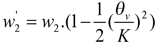
Ainsi, cette valeur de pseudo-vitesse est une estimation de la vitesse que la deuxième roue aurait si elle était sur la même trajectoire que la première roue.Thus, this pseudo-speed value is an estimate of the speed that the second wheel would have if it were on the same trajectory as the first wheel.
Lorsque le véhicule est en ligne droite, la valeur de pseudo-vitesse est ainsi égale à la valeur de vitesse au centre.When the vehicle is in a straight line, the pseudo-speed value is thus equal to the speed value in the center.
Avantageusement et de façon non limitative, on peut prévoir d'appliquer la formule ci-dessus par défaut, et éventuellement de détecter les situations de ligne droite, et de choisir alors des valeurs de pseudo-vitesses directement égales à la valeur de vitesse au centre.Advantageously and in a nonlimiting manner, provision may be made to apply the above formula by default, and possibly to detect the straight line situations, and then to choose values of pseudo-speeds directly equal to the value of speed in the center. .
Alternativement, on peut prévoir de détecter les situations de virage, et d'appliquer la formule ci-dessus seulement en cas de détection d'une situation de virage.Alternatively, it is possible to detect the turning situations, and to apply the above formula only in case of detection of a turning situation.
La consigne de freinage régénérative peut par exemple être complémentaire d'une consigne de freinage non-régénérative appliquée par le deuxième moyen de freinage, supplémentaire par rapport au freinage appliqué par ce deuxième moyen de freinage, ou autre.The regenerative braking setpoint may for example be complementary to a non-regenerative braking setpoint applied by the second braking means, additional to the braking applied by the second braking means, or the like.
L'invention peut trouver une application sur tous les véhicules qui possèdent un actionneur de couple permettant de récupérer de l'énergie, c'est-à-dire notamment les véhicules électriques ou hybrides, et également les véhicules thermiques équipés avec un alternateur, par exemple un alterno-démarreur permettant un couple de freinage important.The invention can find an application on all vehicles which have a torque actuator for recovering energy, that is to say in particular electric or hybrid vehicles, and also the thermal vehicles equipped with an alternator, for example. example an alternator-starter allowing a significant braking torque.
Il est en outre proposé un produit programme d'ordinateur comprenant des instructions pour effectuer les étapes du procédé décrit ci-dessus, lorsque ces instructions sont exécutées par un processeur.There is further provided a computer program product comprising instructions for performing the steps of the method described above, when these instructions are executed by a processor.
Ce programme d'ordinateur peut par exemple être stocké sur un support de type disque dur, être téléchargé ou autre.This computer program can for example be stored on a hard disk type media, be downloaded or other.
Il est en outre proposé un dispositif de contrôle du freinage régénératif selon la revendication 6. Ainsi, ce dispositif peut permettre de mettre en oeuvre le procédé décrit ci-dessus. Ce dispositif peut par exemple comprendre ou être intégré dans un ou plusieurs processeurs, par exemple un microcontrôleur, un microprocesseur ou autre. Les moyens de réception peuvent par exemple comprendre un port d'entrée, une broche d'entrée, ou autre. Les premiers et les deuxièmes moyens de traitement peuvent être distincts ou non. Il peut par exemple s'agir de coeurs de processeur ou CPU (de l'anglais « Central Processing Unit »). Le dispositif peut comprendre en outre des moyens de transmission, par exemple un port de sortie, une broche de sortie, ou autre, pour envoyer la valeur de consigne de freinage régénératif vers le premier moyen de freinage.In addition, a regenerative braking control device according to claim 6 is provided. Thus, this device can make it possible to implement the method described above. This device can for example include or be integrated in one or more processors, for example a microcontroller, a microprocessor or other. The receiving means may for example comprise an input port, an input pin, or the like. The first and second means of treatment may be distinct or not. It may for example be CPU cores or CPU (Central Processing Unit English). The device may further comprise transmission means, for example an output port, an output pin, or the like, for sending the regenerative braking setpoint value to the first braking means.
Les valeurs de vitesse reçues peuvent être issues de capteurs respectifs.The speed values received may be from respective sensors.
Il est en outre proposé un véhicule, par exemple un véhicule automobile, par exemple électrique ou hybride, comprenant le dispositif de contrôle décrit ci-dessus.There is further provided a vehicle, for example a motor vehicle, for example electric or hybrid, comprising the control device described above.
L'invention sera mieux comprise en référence aux figures, lesquelles illustrent des modes de réalisation donnés à titre d'exemple et non limitatifs.
- La
figure 1 est une vue, de dessus et très schématique, d'un exemple de véhicule, selon un mode de réalisation de l'invention. - La
figure 2 représente schématiquement un exemple de dispositif de contrôle selon un mode de réalisation de l'invention. - La
figure 3 est un logigramme d'un exemple de procédé selon un mode de réalisation de l'invention.
- The
figure 1 is a view, from above and very schematic, of an exemplary vehicle, according to one embodiment of the invention. - The
figure 2 schematically represents an example of a control device according to one embodiment of the invention. - The
figure 3 is a logic diagram of an exemplary method according to one embodiment of the invention.
En référence à la
Un module ESC 12 reçoit des valeurs de mesure de capteurs de rotation d'arbres permettant de mesurer des vitesses aux centres des roues avants et des roues arrières. Ce module ESC est en communication, par exemple via un bus CAN (de l'anglais « Controller Area Network ») avec l'actionneur électrique 10.An
La
L'ESC 12 comporte un module de stabilité 20 recevant des valeurs de rotation au centre des roues avants et arrières, ainsi qu'une valeur de pression de freinage P et une valeur d'angle volant θv , issue d'un capteur d'angle volant du véhicule.The
Ce module 20 permet de générer une valeur de drapeau IS et deux valeurs de paramètres représentatifs des glissements liés au freinage électrique des roues arrières gauche et droite respectivement gL et gR.This
Un module de calcul 21 de la consigne conducteur Cg permet, à partir de signaux non représentés et incluant notamment un signal de contacteur stop et un signal de pression maître-cylindre, de générer de valeur de consigne globale Cg correspondant à une estimation de la volonté de freinage du conducteur. Ce type de module de calcul est connu en soi et ne sera pas détaillé davantage.A
Un module de gestion de freinage (« torque manager» en anglais) reçoit la valeur de drapeau IS, les valeurs de paramètre représentatifs des glissements liés au freinage électrique gL gR, et la valeur de consigne de freinage globale Cg, et génère une consigne de freinage électrique Cel en fonction notamment de ces valeurs reçues.A torque management module ("torque manager" in English) receives the IS flag value, the parameter values representative of the slippage related to the electric braking g L g R , and the setpoint value of overall braking Cg, and generates an electric braking setpoint C el in particular according to these received values.
Par exemple lorsque le drapeau IS est à 1, le freinage électrique est désactivé c'est-à-dire que la consigne Cel est nulle.For example, when the IS flag is at 1, the electric braking is deactivated, ie the set point C el is zero.
Lorsque les valeurs gL, gR sont inférieures à un seuil, la valeur de consigne de freinage électrique Cel est choisie proportionnelle à la valeur de consigne de freinage globale Cg par exemple égale à 10 ou 20% de cette valeur.When the values g L , g R are below a threshold, the electric braking setpoint value C el is chosen proportional to the global braking setpoint value Cg, for example equal to 10 or 20% of this value.
La valeur de consigne de freinage électrique supplémentaire Cel est envoyée vers la machine électrique référencée 10 sur la
La
Le procédé comporte une étape 30 de réception des valeurs de vitesses de rotation des roues et de la valeur d'angle volant.The method comprises a
Au cours d'une étape 31 on calcule des valeurs des paramètres gL, gR de glissement liées au freinage régénératif pour les roues arrière gauche et droite respectivement, en appliquant les formules ci-dessous : ![]()
![]()
- R est le rayon des roues supposées identiques d'une roue à l'autre,
- WRL est la vitesse angulaire de rotation au centre de la roue arrière gauche,
- WFL est la vitesse angulaire de rotation au centre de la roue avant gauche,
- WRR est la vitesse angulaire de rotation au centre de la roue arrière droite,
- WFR est la vitesse angulaire de rotation au centre de la roue avant droite,
- θv est la valeur d'angle au volant reçue à l'étape 30, et
- K est une valeur d'un facteur de démultiplication de la colonne de direction.
- R is the radius of the wheels supposed to be identical from one wheel to another,
- W RL is the rotational angular velocity at the center of the left rear wheel,
- W FL is the rotational angular velocity at the center of the left front wheel,
- W RR is the rotational angular velocity at the center of the right rear wheel,
- W FR is the rotational angular velocity at the center of the right front wheel,
- θ v is the steering wheel angle value received in
step 30, and - K is a value of a reduction factor of the steering column.
Puis au cours d'une étape de test 32, on compare ces valeurs gL, gR à un seuil THR.Then during a
Dans cet exemple le test est positif si une des valeurs est supérieure au seuil THR.In this example, the test is positive if one of the values is greater than the threshold THR.
Dans ce cas, la valeur de consigne de freinage électrique Cel est diminuée, par exemple décrémentée de 10%, au cours d'une étape 33.In this case, the electric braking set value C el is decreased, for example decremented by 10%, during a
Puis, après une étape d'attente 34, ces différentes étapes 31, 32, 33 sont réitérées. Une telle boucle fermée permet ainsi d'asservir la valeur de consigne électrique de sorte que le glissement lié au freinage électrique reste en-deçà du seuil THR.Then, after a waiting
La boucle peut comprendre en outre une étape non représentée de transmission de la valeur de consigne de freinage électrique Cel vers l'actionneur électrique, afin qu'une force de freinage correspondant à cette valeur de consigne soit appliquée aux roues arrières.The loop may further comprise a not shown step of transmitting the electric braking set value C el to the electric actuator, so that a braking force corresponding to this set value is applied to the rear wheels.
Ce seuil THR peut être choisi de sorte que le glissement reste dans une zone d'adhérence dans laquelle l'adhérence, c'est-à-dire le rapport entre la force de trainée et le poids, varie linéairement avec le glissement. Dit autrement, on maintient le véhicule dans cette zone d'adhérence.This threshold THR can be chosen so that the slip remains in an adhesion zone in which the adhesion, that is to say the ratio between the drag force and the weight, varies linearly with the slip. In other words, the vehicle is maintained in this zone of adhesion.
Pour revenir à la
Dans le mode de réalisation représenté, le véhicule est un véhicule à propulsion, c'est-à-dire que le freinage électrique s'applique aux roues arrière. Il va de soi que ce procédé pourrait être adapté dans le cas d'un véhicule à traction.In the embodiment shown, the vehicle is a propulsion vehicle, that is to say that the electric braking applies to the rear wheels. It goes without saying that this method could be adapted in the case of a traction vehicle.
Claims (9)
- Method for controlling regenerative braking for a vehicle equipped with a first, regenerative, braking means and with a second braking means separate from the first braking means, the vehicle comprising at least one first wheel and at least one second wheel, the second braking means being applied to said at least one first wheel and to said at least one second wheel, and the first braking means being applied to said at least one first wheel only, the method comprising reception (30) of a speed value of the first wheel and a speed value of the second wheel,
estimation (31) of a value of a parameter representing the slip associated with the regenerative braking as a function of the speed value of the first wheel and as a function of the speed value of the second wheel, the estimation step (31) comprising a calculation of a pseudo-speed value of the second wheel on the basis of the speed value at the center of this second wheel according to:
formation (32, 33) of a regenerative braking setpoint value as a function of the estimated value of the parameter representing slip associated with the regenerative braking. - Method according to Claim 1, comprising comparison (32) of the parameter value representing the slip associated with the regenerative braking with a slip threshold, and
if this value is greater than or equal to this threshold, instigation (33) of a decrease of the regenerative braking setpoint value. - Method according to Claim 2, wherein the steps of reception (30), of estimation (31) of the value of the parameter representing the slip associated with the regenerative braking, of comparison (32) of said value with the slip threshold, and of instigation (33) of a decrease of the regenerative braking setpoint value are optionally repeated regularly.
- Method according to any one of Claims 1 to 3, wherein the value of the parameter representing the slip associated with the regenerative braking for a first wheel is estimated as a function of a speed value of the second wheel lying on the same side of the vehicle as this first wheel.
- Computer program product comprising instructions for carrying out the steps of the method according to any one of Claims 1 to 4 when these instructions are executed by a processor.
- Device (12) for controlling regenerative braking for a vehicle equipped with a first, regenerative, braking means and with a second braking means separate from the first braking means, the vehicle comprising at least one first wheel and at least one second wheel, one first wheel and to said at least one second wheel, and the first braking means being applied to said at least one first wheel only, the control device comprising:reception means (20) for receiving a speed value of the first wheel and a speed value of the second wheel, first processing means (20) for estimating a value of a parameter representing the slip associated with the regenerative braking as a function of the speed value of the first wheel and as a function of the speed value of the second wheel, this estimation being carried out by calculating a pseudo-speed value of the second wheel on the basis of the speed value at the center of this second wheel according to:

second processing means (22) for forming a regenerative braking setpoint value as a function of the estimated value of the parameter representing slip associated with the regenerative braking. - Motor vehicle (1) equipped with a first, regenerative, braking means (10) and with a second braking means separate from the first braking means, the vehicle comprising at least one first wheel (11RL, 11RR) and at least one second wheel (11FL, 11FR), the second braking means being applied to said at least one first wheel and to said at least one second wheel, and the first braking means being applied to said at least one first wheel only, and comprising the control device (12) according to Claim 7.
- Motor vehicle (1) according to Claim 7, comprising an electrical actuator (10).
- Motor vehicle (1) according to one of Claims 7 and 8, wherein the first wheels are the rear wheels (11RL, 11RR)
Applications Claiming Priority (2)
| Application Number | Priority Date | Filing Date | Title |
|---|---|---|---|
| FR1357803A FR3009524B1 (en) | 2013-08-06 | 2013-08-06 | CONTROL OF REGENERATIVE BRAKING IN AN ELECTRIC OR HYBRID VEHICLE |
| PCT/FR2014/051732 WO2015018994A2 (en) | 2013-08-06 | 2014-07-04 | Control of regenerative braking in an electric or hybrid vehicle |
Publications (2)
| Publication Number | Publication Date |
|---|---|
| EP3030449A2 EP3030449A2 (en) | 2016-06-15 |
| EP3030449B1 true EP3030449B1 (en) | 2017-08-30 |
Family
ID=49578435
Family Applications (1)
| Application Number | Title | Priority Date | Filing Date |
|---|---|---|---|
| EP14748241.8A Active EP3030449B1 (en) | 2013-08-06 | 2014-07-04 | Control of regenerative braking in an electric or hybrid vehicle |
Country Status (7)
| Country | Link |
|---|---|
| US (1) | US10052957B2 (en) |
| EP (1) | EP3030449B1 (en) |
| JP (1) | JP6396465B2 (en) |
| KR (1) | KR102030714B1 (en) |
| CN (1) | CN105593052B (en) |
| FR (1) | FR3009524B1 (en) |
| WO (1) | WO2015018994A2 (en) |
Families Citing this family (9)
| Publication number | Priority date | Publication date | Assignee | Title |
|---|---|---|---|---|
| ITTO20130307A1 (en) | 2013-04-17 | 2014-10-18 | Itt Italia Srl | METHOD TO REALIZE A BRAKE ELEMENT, IN PARTICULAR A BRAKE PAD, SENSORIZED, SENSORED BRAKE PAD, VEHICLE BRAKE SYSTEM AND ASSOCIATED METHOD |
| US9939035B2 (en) | 2015-05-28 | 2018-04-10 | Itt Italia S.R.L. | Smart braking devices, systems, and methods |
| ITUB20153709A1 (en) | 2015-09-17 | 2017-03-17 | Itt Italia Srl | DATA ANALYSIS AND MANAGEMENT DEVICE GENERATED BY A SENSORIZED BRAKE SYSTEM FOR VEHICLES |
| ITUB20153706A1 (en) | 2015-09-17 | 2017-03-17 | Itt Italia Srl | BRAKING DEVICE FOR HEAVY VEHICLE AND METHOD OF PREVENTING BRAKE OVERHEATING IN A HEAVY VEHICLE |
| ITUA20161336A1 (en) * | 2016-03-03 | 2017-09-03 | Itt Italia Srl | DEVICE AND METHOD FOR IMPROVING THE PERFORMANCE OF A VEHICLE ANTI-LOCK AND ANTI-SLIP SYSTEM |
| IT201600077944A1 (en) | 2016-07-25 | 2018-01-25 | Itt Italia Srl | DEVICE FOR DETECTION OF RESIDUAL BRAKING TORQUE IN A VEHICLE EQUIPPED WITH DISC BRAKES |
| IT201900015839A1 (en) | 2019-09-06 | 2021-03-06 | Itt Italia Srl | BRAKE PAD FOR VEHICLES AND ITS PRODUCTION PROCESS |
| CN113071326B (en) * | 2021-05-06 | 2022-05-03 | 东风汽车集团股份有限公司 | Method and system for distributing regenerated energy recovery torque of four-wheel drive new energy automobile |
| CN117377603A (en) | 2021-05-25 | 2024-01-09 | 意大利Itt有限责任公司 | Method and device for estimating the residual torque between a braked element and a braking element of a vehicle |
Family Cites Families (37)
| Publication number | Priority date | Publication date | Assignee | Title |
|---|---|---|---|---|
| US5615933A (en) * | 1995-05-31 | 1997-04-01 | General Motors Corporation | Electric vehicle with regenerative and anti-lock braking |
| JP3622395B2 (en) * | 1997-01-17 | 2005-02-23 | トヨタ自動車株式会社 | Braking device |
| JP3442266B2 (en) * | 1997-09-16 | 2003-09-02 | トヨタ自動車株式会社 | Vehicle braking system |
| JP2001526151A (en) * | 1997-12-20 | 2001-12-18 | コンティネンタル・テーベス・アクチエンゲゼルシヤフト・ウント・コンパニー・オッフェネ・ハンデルスゲゼルシヤフト | Method and apparatus for improving the running characteristics of a vehicle during a braking curve |
| JP3763231B2 (en) * | 1999-06-04 | 2006-04-05 | トヨタ自動車株式会社 | Braking device |
| US6575870B2 (en) * | 2000-07-21 | 2003-06-10 | Honda Giken Kogyo Kabushiki Kaisha | Driving force control system for front-and-rear wheel drive vehicles |
| JP4108258B2 (en) * | 2000-07-27 | 2008-06-25 | 本田技研工業株式会社 | Driving force control device for front and rear wheel drive vehicle |
| JP3811372B2 (en) * | 2001-05-30 | 2006-08-16 | トヨタ自動車株式会社 | Braking force control device for vehicle |
| JP4039146B2 (en) * | 2001-09-27 | 2008-01-30 | 日産自動車株式会社 | Braking control device |
| JP2004155390A (en) * | 2002-11-08 | 2004-06-03 | Nissan Motor Co Ltd | Braking device for vehicle |
| US7159954B2 (en) * | 2003-12-29 | 2007-01-09 | Bendix Commercial Vehicle Systems, Llc | ABS control system for off-road driving conditions |
| US8066339B2 (en) * | 2004-03-09 | 2011-11-29 | Ford Global Technologies, Llc | Vehicle and method for controlling regenerative braking |
| JP2006081343A (en) * | 2004-09-10 | 2006-03-23 | Nissan Motor Co Ltd | Regenerative braking control device for vehicle |
| JP4631477B2 (en) * | 2005-03-04 | 2011-02-16 | 日産自動車株式会社 | Vehicle regenerative braking control device |
| KR101006987B1 (en) * | 2005-12-07 | 2011-01-12 | 주식회사 만도 | Regenerative Brake Control Method for Vehicle equipped with the Electric Motor |
| US8315751B2 (en) * | 2008-02-29 | 2012-11-20 | GM Global Technology Operations LLC | Methods, program products, and systems for controlling braking in a hybrid vehicle |
| JP2009278840A (en) * | 2008-05-19 | 2009-11-26 | Nissan Motor Co Ltd | Regenerative braking control unit of electric vehicle |
| US8239112B2 (en) * | 2008-07-16 | 2012-08-07 | Ford Global Technologies | Pressure, tire force and friction estimation during antilock control |
| US8700241B2 (en) * | 2009-10-19 | 2014-04-15 | Toyota Jidosha Kabushiki Kaisha | Drive control device for standby four-wheel drive vehicle |
| EP2543536B1 (en) * | 2010-03-02 | 2019-05-01 | Toyota Jidosha Kabushiki Kaisha | Regeneration control system for vehicle |
| DE102010033496B4 (en) * | 2010-08-05 | 2024-03-28 | Zf Active Safety Gmbh | Technique for operating a braking system in a μ-split situation |
| US9175701B2 (en) * | 2010-09-02 | 2015-11-03 | Kelsey-Hayes Company | Speed control strategy |
| JP5768352B2 (en) * | 2010-10-08 | 2015-08-26 | 日産自動車株式会社 | Brake control device for electric vehicle |
| US8639402B2 (en) * | 2010-11-04 | 2014-01-28 | Caterpillar Inc. | System and method for controlling wheel motor torque in an electric drive system |
| US20120133202A1 (en) * | 2010-11-29 | 2012-05-31 | Gm Global Technology Operations, Inc. | Dynamic regenerative braking torque control |
| JP5387597B2 (en) * | 2011-03-02 | 2014-01-15 | トヨタ自動車株式会社 | Vehicle control device |
| JP5699041B2 (en) * | 2011-06-15 | 2015-04-08 | 日立オートモティブシステムズ株式会社 | Brake control device |
| KR20140053701A (en) * | 2012-10-26 | 2014-05-08 | 현대자동차주식회사 | System for controlling of e-4wd hybrid electricity vehicle and method thereof |
| US8862358B2 (en) * | 2013-03-15 | 2014-10-14 | Ford Global Technologies, Llc | Vehicle and method for controlling regenerative braking |
| JP6115944B2 (en) * | 2013-05-27 | 2017-04-19 | 日立オートモティブシステムズ株式会社 | Brake device and brake system |
| JP6049540B2 (en) * | 2013-05-31 | 2016-12-21 | 日立オートモティブシステムズ株式会社 | Brake control device |
| JP6063824B2 (en) * | 2013-06-21 | 2017-01-18 | 日立オートモティブシステムズ株式会社 | Brake control device |
| JP6167364B2 (en) * | 2013-09-17 | 2017-07-26 | 日立オートモティブシステムズ株式会社 | Brake control device and brake control method |
| KR101519227B1 (en) * | 2013-10-18 | 2015-05-11 | 현대자동차주식회사 | Controlling method and system for operating Anti-lock Brake System of vehicle |
| US9457777B2 (en) * | 2014-07-16 | 2016-10-04 | Ford Global Technologies, Llc | System and method for applying regenerative braking during high friction coefficient braking |
| US9308824B1 (en) * | 2014-10-31 | 2016-04-12 | GM Global Technology Operations LLC | Active brake retraction during regeneration |
| ITUA20161336A1 (en) * | 2016-03-03 | 2017-09-03 | Itt Italia Srl | DEVICE AND METHOD FOR IMPROVING THE PERFORMANCE OF A VEHICLE ANTI-LOCK AND ANTI-SLIP SYSTEM |
-
2013
- 2013-08-06 FR FR1357803A patent/FR3009524B1/en active Active
-
2014
- 2014-07-04 WO PCT/FR2014/051732 patent/WO2015018994A2/en active Application Filing
- 2014-07-04 KR KR1020167005765A patent/KR102030714B1/en active IP Right Grant
- 2014-07-04 JP JP2016532713A patent/JP6396465B2/en active Active
- 2014-07-04 US US14/909,206 patent/US10052957B2/en active Active
- 2014-07-04 CN CN201480051505.9A patent/CN105593052B/en active Active
- 2014-07-04 EP EP14748241.8A patent/EP3030449B1/en active Active
Also Published As
| Publication number | Publication date |
|---|---|
| EP3030449A2 (en) | 2016-06-15 |
| WO2015018994A3 (en) | 2015-04-16 |
| CN105593052A (en) | 2016-05-18 |
| JP2016527867A (en) | 2016-09-08 |
| CN105593052B (en) | 2018-06-05 |
| FR3009524B1 (en) | 2016-11-18 |
| JP6396465B2 (en) | 2018-09-26 |
| WO2015018994A2 (en) | 2015-02-12 |
| US20160257204A1 (en) | 2016-09-08 |
| US10052957B2 (en) | 2018-08-21 |
| KR20160040667A (en) | 2016-04-14 |
| FR3009524A1 (en) | 2015-02-13 |
| KR102030714B1 (en) | 2019-10-10 |
Similar Documents
| Publication | Publication Date | Title |
|---|---|---|
| EP3030449B1 (en) | Control of regenerative braking in an electric or hybrid vehicle | |
| EP2217476B1 (en) | System for controlling a vehicle with determination of the speed thereof relative to the ground | |
| EP2758257B1 (en) | Method for estimating the rolling resistance of a vehicle wheel | |
| EP2895826B1 (en) | Device and method for estimating the charge of a motor vehicle | |
| CN104470783B (en) | The method for detecting the out of season acceleration of motor vehicles | |
| EP3030447B1 (en) | Control of regenerative braking in an electric or hybrid vehicle | |
| EP2870038B1 (en) | System and method for monitoring the trajectory of a vehicle | |
| EP2307253B1 (en) | Device for evaluating the transverse acceleration of a motor vehicle and corresponding method | |
| EP2082939B1 (en) | Method and system for estimating grip in an automobile | |
| FR2902048A1 (en) | SYSTEM AND METHOD FOR CONTROLLING EFFORTS APPLIED TO FRONT AND REAR AXLES OF A FOUR-WHEEL DRIVEN HYBRID MOTOR VEHICLE | |
| EP2766232B1 (en) | Regenerative braking setpoint matching | |
| EP2528788B1 (en) | System and method for tracking the path of a vehicle | |
| WO2007045787A1 (en) | Method for validating the measurement supplied by an accelerometer in a motor vehicle and use for estimating slope | |
| EP1940662B1 (en) | Method for determining the condition of a motor vehicle wheels and device therefor | |
| EP2830895B1 (en) | Method for estimating the rolling resistance of a vehicle wheel | |
| EP1538042B1 (en) | System and method for controlling the acceleration of a vehicle on a slope | |
| EP2069173B1 (en) | Method and system for controlling a vehicle equipped with a controlled braking system and with a four-wheel steering system | |
| FR2932878A1 (en) | Terrain inclination estimating device for four-wheel drive motor vehicle, has calculator providing inclination of terrain from instantaneous acceleration signals provided by accelerometers | |
| EP2176111B1 (en) | Method for estimating the sliding of the wheels of a vehicle and device for implementing same | |
| FR2932892A1 (en) | Speed i.e. displacement speed, estimation device for four motorized wheeled motor vehicle, has logic controller providing speed of vehicle from acceleration signals provided by accelerometers | |
| FR2922026A3 (en) | Motor vehicle e.g. four-wheel drive vehicle, longitudinal speed estimating method for e.g. wheel anti-blocking system, involves estimating speed of any non sliding wheels when wheels do not slide | |
| WO2007045788A1 (en) | Device for measuring acceleration in a motor vehicle |
Legal Events
| Date | Code | Title | Description |
|---|---|---|---|
| PUAI | Public reference made under article 153(3) epc to a published international application that has entered the european phase |
Free format text: ORIGINAL CODE: 0009012 |
|
| 17P | Request for examination filed |
Effective date: 20160119 |
|
| AK | Designated contracting states |
Kind code of ref document: A2 Designated state(s): AL AT BE BG CH CY CZ DE DK EE ES FI FR GB GR HR HU IE IS IT LI LT LU LV MC MK MT NL NO PL PT RO RS SE SI SK SM TR |
|
| AX | Request for extension of the european patent |
Extension state: BA ME |
|
| DAX | Request for extension of the european patent (deleted) | ||
| GRAJ | Information related to disapproval of communication of intention to grant by the applicant or resumption of examination proceedings by the epo deleted |
Free format text: ORIGINAL CODE: EPIDOSDIGR1 |
|
| GRAP | Despatch of communication of intention to grant a patent |
Free format text: ORIGINAL CODE: EPIDOSNIGR1 |
|
| STAA | Information on the status of an ep patent application or granted ep patent |
Free format text: STATUS: REQUEST FOR EXAMINATION WAS MADE |
|
| RIC1 | Information provided on ipc code assigned before grant |
Ipc: B60W 10/184 20120101ALI20161213BHEP Ipc: B60L 3/10 20060101AFI20161213BHEP Ipc: B60T 8/1761 20060101ALI20161213BHEP Ipc: B60W 30/18 20120101ALI20161213BHEP Ipc: B60W 10/08 20060101ALI20161213BHEP Ipc: B60L 7/26 20060101ALI20161213BHEP Ipc: B60L 7/18 20060101ALI20161213BHEP Ipc: B60L 15/20 20060101ALI20161213BHEP |
|
| GRAP | Despatch of communication of intention to grant a patent |
Free format text: ORIGINAL CODE: EPIDOSNIGR1 |
|
| STAA | Information on the status of an ep patent application or granted ep patent |
Free format text: STATUS: GRANT OF PATENT IS INTENDED |
|
| INTG | Intention to grant announced |
Effective date: 20170125 |
|
| GRAS | Grant fee paid |
Free format text: ORIGINAL CODE: EPIDOSNIGR3 |
|
| GRAA | (expected) grant |
Free format text: ORIGINAL CODE: 0009210 |
|
| STAA | Information on the status of an ep patent application or granted ep patent |
Free format text: STATUS: THE PATENT HAS BEEN GRANTED |
|
| AK | Designated contracting states |
Kind code of ref document: B1 Designated state(s): AL AT BE BG CH CY CZ DE DK EE ES FI FR GB GR HR HU IE IS IT LI LT LU LV MC MK MT NL NO PL PT RO RS SE SI SK SM TR |
|
| REG | Reference to a national code |
Ref country code: GB Ref legal event code: FG4D Free format text: NOT ENGLISH |
|
| REG | Reference to a national code |
Ref country code: CH Ref legal event code: EP |
|
| REG | Reference to a national code |
Ref country code: AT Ref legal event code: REF Ref document number: 923170 Country of ref document: AT Kind code of ref document: T Effective date: 20170915 |
|
| REG | Reference to a national code |
Ref country code: IE Ref legal event code: FG4D Free format text: LANGUAGE OF EP DOCUMENT: FRENCH |
|
| REG | Reference to a national code |
Ref country code: DE Ref legal event code: R096 Ref document number: 602014013880 Country of ref document: DE |
|
| REG | Reference to a national code |
Ref country code: NL Ref legal event code: MP Effective date: 20170830 |
|
| REG | Reference to a national code |
Ref country code: LT Ref legal event code: MG4D |
|
| REG | Reference to a national code |
Ref country code: AT Ref legal event code: MK05 Ref document number: 923170 Country of ref document: AT Kind code of ref document: T Effective date: 20170830 |
|
| PG25 | Lapsed in a contracting state [announced via postgrant information from national office to epo] |
Ref country code: LT Free format text: LAPSE BECAUSE OF FAILURE TO SUBMIT A TRANSLATION OF THE DESCRIPTION OR TO PAY THE FEE WITHIN THE PRESCRIBED TIME-LIMIT Effective date: 20170830 Ref country code: NO Free format text: LAPSE BECAUSE OF FAILURE TO SUBMIT A TRANSLATION OF THE DESCRIPTION OR TO PAY THE FEE WITHIN THE PRESCRIBED TIME-LIMIT Effective date: 20171130 Ref country code: SE Free format text: LAPSE BECAUSE OF FAILURE TO SUBMIT A TRANSLATION OF THE DESCRIPTION OR TO PAY THE FEE WITHIN THE PRESCRIBED TIME-LIMIT Effective date: 20170830 Ref country code: AT Free format text: LAPSE BECAUSE OF FAILURE TO SUBMIT A TRANSLATION OF THE DESCRIPTION OR TO PAY THE FEE WITHIN THE PRESCRIBED TIME-LIMIT Effective date: 20170830 Ref country code: FI Free format text: LAPSE BECAUSE OF FAILURE TO SUBMIT A TRANSLATION OF THE DESCRIPTION OR TO PAY THE FEE WITHIN THE PRESCRIBED TIME-LIMIT Effective date: 20170830 Ref country code: HR Free format text: LAPSE BECAUSE OF FAILURE TO SUBMIT A TRANSLATION OF THE DESCRIPTION OR TO PAY THE FEE WITHIN THE PRESCRIBED TIME-LIMIT Effective date: 20170830 |
|
| PG25 | Lapsed in a contracting state [announced via postgrant information from national office to epo] |
Ref country code: ES Free format text: LAPSE BECAUSE OF FAILURE TO SUBMIT A TRANSLATION OF THE DESCRIPTION OR TO PAY THE FEE WITHIN THE PRESCRIBED TIME-LIMIT Effective date: 20170830 Ref country code: LV Free format text: LAPSE BECAUSE OF FAILURE TO SUBMIT A TRANSLATION OF THE DESCRIPTION OR TO PAY THE FEE WITHIN THE PRESCRIBED TIME-LIMIT Effective date: 20170830 Ref country code: RS Free format text: LAPSE BECAUSE OF FAILURE TO SUBMIT A TRANSLATION OF THE DESCRIPTION OR TO PAY THE FEE WITHIN THE PRESCRIBED TIME-LIMIT Effective date: 20170830 Ref country code: GR Free format text: LAPSE BECAUSE OF FAILURE TO SUBMIT A TRANSLATION OF THE DESCRIPTION OR TO PAY THE FEE WITHIN THE PRESCRIBED TIME-LIMIT Effective date: 20171201 Ref country code: BG Free format text: LAPSE BECAUSE OF FAILURE TO SUBMIT A TRANSLATION OF THE DESCRIPTION OR TO PAY THE FEE WITHIN THE PRESCRIBED TIME-LIMIT Effective date: 20171130 Ref country code: IS Free format text: LAPSE BECAUSE OF FAILURE TO SUBMIT A TRANSLATION OF THE DESCRIPTION OR TO PAY THE FEE WITHIN THE PRESCRIBED TIME-LIMIT Effective date: 20171230 |
|
| PG25 | Lapsed in a contracting state [announced via postgrant information from national office to epo] |
Ref country code: NL Free format text: LAPSE BECAUSE OF FAILURE TO SUBMIT A TRANSLATION OF THE DESCRIPTION OR TO PAY THE FEE WITHIN THE PRESCRIBED TIME-LIMIT Effective date: 20170830 |
|
| PG25 | Lapsed in a contracting state [announced via postgrant information from national office to epo] |
Ref country code: CZ Free format text: LAPSE BECAUSE OF FAILURE TO SUBMIT A TRANSLATION OF THE DESCRIPTION OR TO PAY THE FEE WITHIN THE PRESCRIBED TIME-LIMIT Effective date: 20170830 Ref country code: DK Free format text: LAPSE BECAUSE OF FAILURE TO SUBMIT A TRANSLATION OF THE DESCRIPTION OR TO PAY THE FEE WITHIN THE PRESCRIBED TIME-LIMIT Effective date: 20170830 Ref country code: PL Free format text: LAPSE BECAUSE OF FAILURE TO SUBMIT A TRANSLATION OF THE DESCRIPTION OR TO PAY THE FEE WITHIN THE PRESCRIBED TIME-LIMIT Effective date: 20170830 Ref country code: RO Free format text: LAPSE BECAUSE OF FAILURE TO SUBMIT A TRANSLATION OF THE DESCRIPTION OR TO PAY THE FEE WITHIN THE PRESCRIBED TIME-LIMIT Effective date: 20170830 |
|
| PG25 | Lapsed in a contracting state [announced via postgrant information from national office to epo] |
Ref country code: IT Free format text: LAPSE BECAUSE OF FAILURE TO SUBMIT A TRANSLATION OF THE DESCRIPTION OR TO PAY THE FEE WITHIN THE PRESCRIBED TIME-LIMIT Effective date: 20170830 Ref country code: SM Free format text: LAPSE BECAUSE OF FAILURE TO SUBMIT A TRANSLATION OF THE DESCRIPTION OR TO PAY THE FEE WITHIN THE PRESCRIBED TIME-LIMIT Effective date: 20170830 Ref country code: SK Free format text: LAPSE BECAUSE OF FAILURE TO SUBMIT A TRANSLATION OF THE DESCRIPTION OR TO PAY THE FEE WITHIN THE PRESCRIBED TIME-LIMIT Effective date: 20170830 Ref country code: EE Free format text: LAPSE BECAUSE OF FAILURE TO SUBMIT A TRANSLATION OF THE DESCRIPTION OR TO PAY THE FEE WITHIN THE PRESCRIBED TIME-LIMIT Effective date: 20170830 |
|
| REG | Reference to a national code |
Ref country code: DE Ref legal event code: R097 Ref document number: 602014013880 Country of ref document: DE |
|
| PLBE | No opposition filed within time limit |
Free format text: ORIGINAL CODE: 0009261 |
|
| STAA | Information on the status of an ep patent application or granted ep patent |
Free format text: STATUS: NO OPPOSITION FILED WITHIN TIME LIMIT |
|
| REG | Reference to a national code |
Ref country code: FR Ref legal event code: PLFP Year of fee payment: 5 |
|
| 26N | No opposition filed |
Effective date: 20180531 |
|
| PG25 | Lapsed in a contracting state [announced via postgrant information from national office to epo] |
Ref country code: SI Free format text: LAPSE BECAUSE OF FAILURE TO SUBMIT A TRANSLATION OF THE DESCRIPTION OR TO PAY THE FEE WITHIN THE PRESCRIBED TIME-LIMIT Effective date: 20170830 |
|
| PG25 | Lapsed in a contracting state [announced via postgrant information from national office to epo] |
Ref country code: MT Free format text: LAPSE BECAUSE OF FAILURE TO SUBMIT A TRANSLATION OF THE DESCRIPTION OR TO PAY THE FEE WITHIN THE PRESCRIBED TIME-LIMIT Effective date: 20170830 |
|
| REG | Reference to a national code |
Ref country code: CH Ref legal event code: PL |
|
| PG25 | Lapsed in a contracting state [announced via postgrant information from national office to epo] |
Ref country code: LU Free format text: LAPSE BECAUSE OF NON-PAYMENT OF DUE FEES Effective date: 20180704 Ref country code: MC Free format text: LAPSE BECAUSE OF FAILURE TO SUBMIT A TRANSLATION OF THE DESCRIPTION OR TO PAY THE FEE WITHIN THE PRESCRIBED TIME-LIMIT Effective date: 20170830 |
|
| REG | Reference to a national code |
Ref country code: BE Ref legal event code: MM Effective date: 20180731 |
|
| REG | Reference to a national code |
Ref country code: IE Ref legal event code: MM4A |
|
| PG25 | Lapsed in a contracting state [announced via postgrant information from national office to epo] |
Ref country code: IE Free format text: LAPSE BECAUSE OF NON-PAYMENT OF DUE FEES Effective date: 20180704 Ref country code: LI Free format text: LAPSE BECAUSE OF NON-PAYMENT OF DUE FEES Effective date: 20180731 Ref country code: CH Free format text: LAPSE BECAUSE OF NON-PAYMENT OF DUE FEES Effective date: 20180731 |
|
| PG25 | Lapsed in a contracting state [announced via postgrant information from national office to epo] |
Ref country code: BE Free format text: LAPSE BECAUSE OF NON-PAYMENT OF DUE FEES Effective date: 20180731 |
|
| PG25 | Lapsed in a contracting state [announced via postgrant information from national office to epo] |
Ref country code: TR Free format text: LAPSE BECAUSE OF FAILURE TO SUBMIT A TRANSLATION OF THE DESCRIPTION OR TO PAY THE FEE WITHIN THE PRESCRIBED TIME-LIMIT Effective date: 20170830 |
|
| PG25 | Lapsed in a contracting state [announced via postgrant information from national office to epo] |
Ref country code: PT Free format text: LAPSE BECAUSE OF FAILURE TO SUBMIT A TRANSLATION OF THE DESCRIPTION OR TO PAY THE FEE WITHIN THE PRESCRIBED TIME-LIMIT Effective date: 20170830 |
|
| PG25 | Lapsed in a contracting state [announced via postgrant information from national office to epo] |
Ref country code: MK Free format text: LAPSE BECAUSE OF NON-PAYMENT OF DUE FEES Effective date: 20170830 Ref country code: HU Free format text: LAPSE BECAUSE OF FAILURE TO SUBMIT A TRANSLATION OF THE DESCRIPTION OR TO PAY THE FEE WITHIN THE PRESCRIBED TIME-LIMIT; INVALID AB INITIO Effective date: 20140704 Ref country code: CY Free format text: LAPSE BECAUSE OF FAILURE TO SUBMIT A TRANSLATION OF THE DESCRIPTION OR TO PAY THE FEE WITHIN THE PRESCRIBED TIME-LIMIT Effective date: 20170830 |
|
| PG25 | Lapsed in a contracting state [announced via postgrant information from national office to epo] |
Ref country code: AL Free format text: LAPSE BECAUSE OF FAILURE TO SUBMIT A TRANSLATION OF THE DESCRIPTION OR TO PAY THE FEE WITHIN THE PRESCRIBED TIME-LIMIT Effective date: 20170830 |
|
| P01 | Opt-out of the competence of the unified patent court (upc) registered |
Effective date: 20230608 |
|
| PGFP | Annual fee paid to national office [announced via postgrant information from national office to epo] |
Ref country code: GB Payment date: 20230721 Year of fee payment: 10 |
|
| PGFP | Annual fee paid to national office [announced via postgrant information from national office to epo] |
Ref country code: FR Payment date: 20230726 Year of fee payment: 10 Ref country code: DE Payment date: 20230719 Year of fee payment: 10 |