EP1538042B1 - System and method for controlling the acceleration of a vehicle on a slope - Google Patents
System and method for controlling the acceleration of a vehicle on a slope Download PDFInfo
- Publication number
- EP1538042B1 EP1538042B1 EP04300835A EP04300835A EP1538042B1 EP 1538042 B1 EP1538042 B1 EP 1538042B1 EP 04300835 A EP04300835 A EP 04300835A EP 04300835 A EP04300835 A EP 04300835A EP 1538042 B1 EP1538042 B1 EP 1538042B1
- Authority
- EP
- European Patent Office
- Prior art keywords
- vehicle
- acceleration
- braking
- algebraic
- transmitted
- Prior art date
- Legal status (The legal status is an assumption and is not a legal conclusion. Google has not performed a legal analysis and makes no representation as to the accuracy of the status listed.)
- Not-in-force
Links
Images

Classifications
-
- B—PERFORMING OPERATIONS; TRANSPORTING
- B60—VEHICLES IN GENERAL
- B60T—VEHICLE BRAKE CONTROL SYSTEMS OR PARTS THEREOF; BRAKE CONTROL SYSTEMS OR PARTS THEREOF, IN GENERAL; ARRANGEMENT OF BRAKING ELEMENTS ON VEHICLES IN GENERAL; PORTABLE DEVICES FOR PREVENTING UNWANTED MOVEMENT OF VEHICLES; VEHICLE MODIFICATIONS TO FACILITATE COOLING OF BRAKES
- B60T7/00—Brake-action initiating means
- B60T7/12—Brake-action initiating means for automatic initiation; for initiation not subject to will of driver or passenger
- B60T7/122—Brake-action initiating means for automatic initiation; for initiation not subject to will of driver or passenger for locking of reverse movement
-
- B—PERFORMING OPERATIONS; TRANSPORTING
- B60—VEHICLES IN GENERAL
- B60T—VEHICLE BRAKE CONTROL SYSTEMS OR PARTS THEREOF; BRAKE CONTROL SYSTEMS OR PARTS THEREOF, IN GENERAL; ARRANGEMENT OF BRAKING ELEMENTS ON VEHICLES IN GENERAL; PORTABLE DEVICES FOR PREVENTING UNWANTED MOVEMENT OF VEHICLES; VEHICLE MODIFICATIONS TO FACILITATE COOLING OF BRAKES
- B60T2201/00—Particular use of vehicle brake systems; Special systems using also the brakes; Special software modules within the brake system controller
- B60T2201/04—Hill descent control
-
- B—PERFORMING OPERATIONS; TRANSPORTING
- B60—VEHICLES IN GENERAL
- B60W—CONJOINT CONTROL OF VEHICLE SUB-UNITS OF DIFFERENT TYPE OR DIFFERENT FUNCTION; CONTROL SYSTEMS SPECIALLY ADAPTED FOR HYBRID VEHICLES; ROAD VEHICLE DRIVE CONTROL SYSTEMS FOR PURPOSES NOT RELATED TO THE CONTROL OF A PARTICULAR SUB-UNIT
- B60W2510/00—Input parameters relating to a particular sub-units
- B60W2510/06—Combustion engines, Gas turbines
- B60W2510/0657—Engine torque
-
- B—PERFORMING OPERATIONS; TRANSPORTING
- B60—VEHICLES IN GENERAL
- B60W—CONJOINT CONTROL OF VEHICLE SUB-UNITS OF DIFFERENT TYPE OR DIFFERENT FUNCTION; CONTROL SYSTEMS SPECIALLY ADAPTED FOR HYBRID VEHICLES; ROAD VEHICLE DRIVE CONTROL SYSTEMS FOR PURPOSES NOT RELATED TO THE CONTROL OF A PARTICULAR SUB-UNIT
- B60W2520/00—Input parameters relating to overall vehicle dynamics
- B60W2520/10—Longitudinal speed
-
- B—PERFORMING OPERATIONS; TRANSPORTING
- B60—VEHICLES IN GENERAL
- B60W—CONJOINT CONTROL OF VEHICLE SUB-UNITS OF DIFFERENT TYPE OR DIFFERENT FUNCTION; CONTROL SYSTEMS SPECIALLY ADAPTED FOR HYBRID VEHICLES; ROAD VEHICLE DRIVE CONTROL SYSTEMS FOR PURPOSES NOT RELATED TO THE CONTROL OF A PARTICULAR SUB-UNIT
- B60W2540/00—Input parameters relating to occupants
- B60W2540/12—Brake pedal position
-
- B—PERFORMING OPERATIONS; TRANSPORTING
- B60—VEHICLES IN GENERAL
- B60W—CONJOINT CONTROL OF VEHICLE SUB-UNITS OF DIFFERENT TYPE OR DIFFERENT FUNCTION; CONTROL SYSTEMS SPECIALLY ADAPTED FOR HYBRID VEHICLES; ROAD VEHICLE DRIVE CONTROL SYSTEMS FOR PURPOSES NOT RELATED TO THE CONTROL OF A PARTICULAR SUB-UNIT
- B60W2552/00—Input parameters relating to infrastructure
- B60W2552/15—Road slope
-
- B—PERFORMING OPERATIONS; TRANSPORTING
- B60—VEHICLES IN GENERAL
- B60W—CONJOINT CONTROL OF VEHICLE SUB-UNITS OF DIFFERENT TYPE OR DIFFERENT FUNCTION; CONTROL SYSTEMS SPECIALLY ADAPTED FOR HYBRID VEHICLES; ROAD VEHICLE DRIVE CONTROL SYSTEMS FOR PURPOSES NOT RELATED TO THE CONTROL OF A PARTICULAR SUB-UNIT
- B60W2710/00—Output or target parameters relating to a particular sub-units
- B60W2710/18—Braking system
-
- B—PERFORMING OPERATIONS; TRANSPORTING
- B60—VEHICLES IN GENERAL
- B60W—CONJOINT CONTROL OF VEHICLE SUB-UNITS OF DIFFERENT TYPE OR DIFFERENT FUNCTION; CONTROL SYSTEMS SPECIALLY ADAPTED FOR HYBRID VEHICLES; ROAD VEHICLE DRIVE CONTROL SYSTEMS FOR PURPOSES NOT RELATED TO THE CONTROL OF A PARTICULAR SUB-UNIT
- B60W2720/00—Output or target parameters relating to overall vehicle dynamics
- B60W2720/10—Longitudinal speed
- B60W2720/106—Longitudinal acceleration
Definitions
- the present invention relates to a system and method for controlling the acceleration of a motor vehicle in a slope.
- the invention must assist the driver in the maneuvers he undertakes on a slope, to make his vehicle as easy to maneuver on steep slopes as on low slopes.
- WO99 / 29531 discloses a parking assistance system for a vehicle, In this patent application, it is intended to determine a maneuvering situation mainly by means of a detection of the speed of movement of the vehicle. No indication is given as to whether the acceleration of the vehicle is taken into account or whether the road is sloped.
- a system for controlling the acceleration of a motor vehicle in a slope comprising a controllable braking system and an electronic control unit.
- the system comprises a sensor for measuring the longitudinal speed of the vehicle, means for measuring the engine torque transmitted to the vehicle, a position sensor for the brake pedal, measuring means or estimating the slope of the roadway on which the vehicle is engaged, processing means capable of calculating a braking command limiting the acceleration of the vehicle according to said slope, and control means able to apply said control of braking to brake actuators.
- system further comprises auxiliary devices for slowing down, said processing means being able respectively to calculate brake commands for said auxiliary slowing devices, and said control means being able to respectively apply to the auxiliary devices slowing said braking commands.
- the system includes a clutch pedal position sensor and means for providing the engaged gear.
- the means for measuring the engine torque transmitted to the vehicle comprise one or more clutch position sensors and an engine rotation speed sensor, or a gear ratio sensor engaged.
- the pre-processing block when the vehicle is further equipped with an anti-lock braking system of wheels, the pre-processing block further receives at the input a signal indicating whether the anti-lock brake system is active or inactive, and if it is active, stops the processing means.
- the preprocessing block is able to calculate an acceleration setpoint intended for the block, for processing, by an estimation means, or on the basis of a given information, by a sensor of acceleration, and to calculate a brake command using the position of the brake pedal.
- the pre-processing block is able to calculate information indicative of the position of the gear lever, in order to be able to recalculate the longitudinal force transmitted to the driving wheels, during a gear change.
- the preprocessing block is able to calculate said disturbance by integrating the difference between the estimated speed by means of calculation of the the speed of the vehicle and the measured speed, by the method of Forward Euler.
- a braking setpoint is calculated which limits the acceleration of the vehicle as a function of the slope of the roadway on which the vehicle is engaged, on the basis of data comprising the vehicle's algebraic speed, the position of the brake pedal, the position of the vehicle. the clutch pedal, the torque transmitted to the drive wheels, and a value indicative of the engaged ratio and applies said braking setpoint to the brake actuators.
- the vehicle 1 comprises a controllable braking system for applying a braking torque independently to each wheel by means of the brake actuators 2.
- the system further comprises an electronic control unit or ECU 3, connected to a sensor 4 of measurement the longitudinal speed of the vehicle capable of providing the speed algebraic vehicle, and means 5 for measuring the engine torque transmitted to the vehicle 1, respectively by connections 6 and 7.
- Each brake actuator 2 is connected to the electronic control unit 3 by a connection 8.
- the system comprises also a position sensor 9 of the brake pedal and a position sensor 10 of the clutch pedal, connected to the ECU 3 respectively by connections 11 and 12 to the ECU 3.
- Means 13, capable of providing the engaged ratio are connected to the ECU 3 by a connection 14.
- the ECU 3 is able to control an application of a braking torque independently on each wheel 15 by means of control means 16 able to apply a braking command 17 developed by processing means 18 and transmitted to the control means 16.
- the processing means 18 are capable of calculating the brake control 17 limiting the acceleration of the vehicle 1 as a function of the slope of the roadway on which the vehicle 1 is engaged.
- the slope of the roadway is measured or estimated by means 19 connected to the electronic control unit 3 by a connection 20.
- the system may further comprise auxiliary slowdown devices 21 connected to the ECU 3 via a connection 22.
- auxiliary slowdown means 21 may, for example, comprise an eddy current electromagnetic deceleration device, a slowing down by closing the exhaust, a slowing device by resistance to lifting the valves, or more of these devices.
- the processing means 18 are then further capable of calculating braking commands respectively for said auxiliary slowdown devices 21, and said control means 16 are capable of respectively applying to the auxiliary slowing devices 21 said braking commands 17.
- the means 5 for measuring the motor torque transmitted to the vehicle 1 comprise, for example, one or more sensors of position of a clutch and a motor rotation speed sensor, or a gear ratio sensor engaged.
- the system may further comprise an anti-lock wheel system or ABS 23, connected to the ECU 3 via a connection 24.
- ABS 23 anti-lock wheel system
- the electronic control unit 3 receives information from the sensor 4 for measuring the longitudinal speed of the vehicle, means 5 for measuring the engine torque transmitted to the vehicle 1, the brake pedal position sensor 9, the sensor 10 of the vehicle. position of the clutch pedal, means 13 capable of providing the gear engaged, and possibly the ABS system 23.
- the signal from the ABS system 23 indicates whether the ABS system 23 is active or inactive, and if it is active, the processing means 18 stop the process according to the invention.
- the processing means 18 evaluate, from these data, a control of the acceleration of the vehicle 1, and applies it to the vehicle 1.
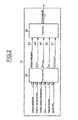
- the figure 2 illustrates the operation of the processing means 11 of a system according to the invention.
- the processing means 18 comprise a pre-treatment block 25 and a treatment block 26.
- the speed of the vehicle is transmitted to the pre-processing block 25 by a connection 27, the position of the brake pedal is transmitted to the pre-processing block 25 by a connection 28, and the position of the clutch pedal is transmitted to the pre-treatment block 25 by a connection 29.
- the torque C emb supplied by the motor is transmitted by a connection 30, and the engaged ratio of the gearbox is transmitted to the pre-processing block 25 by a connection 31.
- the engaged report information is not available on the vehicle 1, means can estimate it, for example, from sensors located at the shifter.
- An optional input 32 may be connected to the pre-processing block 25 to provide a signal to determine whether the anti-lock brake system, for example an ABS system.
- the preprocessing block 25 transmits data via the processing block 26.
- a connection 33 transmits the algebraic speed of the vehicle 1
- a connection 34 transmits an acceleration setpoint A setpoint of the vehicle 1
- a connection 35 transmits a disturbance A disturbance
- a connection 36 transmits a longitudinal force applied to the drive wheels F wheels
- a connection 37 transmits a force F grisngae_conducteur representative of the will of the driver, and due to the action of the driver on the brake pedal.
- the predetermined values of R box , R bridge , and Ray r_m are stored in memory by not shown storage means of the preprocessing block 25.
- the preprocessing block 25 uses an internal function to know when the gear lever passes through the neutral position, to be able to recalculate the longitudinal force applied to the driving wheels during a gear change.
- gbc An example of a function internal to the preprocessing block 25 for providing information representative of the position of the shifter is a function called gbc.
- This function gbc is computed from two entries of type all or nothing or Boolean, b_report_engaged, and b_marche_arrière, not represented on the figure 2 .
- Entry b_report_engage is zero when the gear lever is in neutral, and one when a gear is engaged.
- the entry b_marche_arrière is worth one when the reverse gear is engaged and zero otherwise.
- gbc b_report _engaged- 2 ⁇ b_marche_ bitter
- One possible realization for estimating the perturbation disturbance can be made by means of a model of the braking system, and an estimation of the speed of the vehicle from the value provided by a speed sensor and the command sent to brake actuators.
- the difference between the estimated speed and measured by the sensor makes it possible to deduce the disturbance A integration disturbance known as Forward-Euler.
- the preprocessing block 25 then transmits to the processing block 26, the algebraic speed of the vehicle via a connection 33, the acceleration setpoint A set by a connection 34, the disruption A disturbed by a connection 35, the longitudinal force.
- the processing block 26 limits the acceleration of the vehicle 1 during the maneuvering phases, including when changing the direction of the vehicle 1.
- the processing block 26 continuously compares the set A set acceleration transmitted via the connection 34 and the disturbance A disturbance.
- the set A set acceleration acting only on the brake, is only possible under several conditions: the setpoint acceleration A consinge and disturbance A disturbance must have the same sign, and the absolute value of the setpoint acceleration A setpoint must be lower than the absolute value of the perturbation A perturbation . Indeed, the acceleration of vehicle 1 can not be greater than that which would have been obtained naturally in freewheels.
- a set accelerating the set must have the same sign as the speed of the vehicle 1. This condition allows the system to remain active only when the speed, acceleration and the set A set acceleration have the same sign , that is to say when the vehicle goes down the slope.
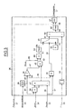
- the figure 3 illustrates an exemplary embodiment of the processing block (26).
- the result of this multiplication is transmitted to an adder / subtractor module 41 via a connection 42.
- the adder / subtractor module 41 subtracts from the result transmitted by the connection 42, the disturbance A disturbance transmitted by the connection 35, and transmits the result to a multiplication module 43 by a connection 44.
- the sign of the speed is transmitted from the memory 38 to an inverter module 45 by a connection 46, which changes the sign of the algebraic speed to its opposite, and transmits the result to the multiplication module 43 by a connection 47.
- the multiplication module 43 then multiplies the two values received by the connections 44 and 47, and transmits the result to a multiplication module 48 by a connection 49.
- a connection 50 also transmits to the multiplication module 48 the vehicle mass M vehicle that multiplied by the acceleration transmitted by the connection 49 gives a force, transmitted by a connection 51 to a filter 52 which transmits the input value if it is positive and a value otherwise zero.
- the output of the filter 52 is transmitted to a selection element 53 via a connection 54.
- the sign of the algebraic speed is transmitted to a multiplication module 55 by a connection 56, and disturbance A disturbance by a connection 57.
- the module 57 performs the product of its two inputs, and transmits the result to the module.
- selection 53 by a connection 58. If the value transmitted by the connection 58 is positive, then the selection module 53 selects and transmits the input transmitted by the connection 54, and otherwise transmits the null value stored in a memory 59 and transmitted by a connection 60.
- the output of the selection module 53 is transmitted by a connection 61 to an adder / subtractor module 62, which will subtract from this value the absolute value of the longitudinal force applied to the driving wheels F wheels .
- the absolute value of the longitudinal force applied to the driving wheels F wheels is calculated by a module 63, which receives as input the longitudinal force applied to the drive wheels F wheels by the connection 36, and is transmitted by a connection 64 to the adder / subtractor module 62.
- the result of the computation performed by the subtractor adder module 62 is transmitted to a filter 65 by a connection 66.
- the filter 65 transmits the input value if it is positive and a value otherwise zero.
- the output of the filter 65 is transmitted to a selection element of maximum 67 by a connection 68.
- the maximum selection element 67 also receives the input, via the connection 37, the force F braking driver due to the action of the driver on the brake pedal, and outputs the maximum of the two values received by the inputs 37 and 68 the brake control 17 for the brake actuators 2.
- the invention thus makes it possible to assist the driver of a vehicle when he performs sloping maneuvers, making the vehicle as easy to drive on a steep slope as on a low slope or in the absence of a slope.
Abstract
Description
La présente invention porte sur un système et un procédé de commande de l'accélération d'un véhicule automobile dans une pente.The present invention relates to a system and method for controlling the acceleration of a motor vehicle in a slope.
Il existe des systèmes permettant d'appliquer des actions de freinage indépendamment de l'action et de la volonté du conducteur. Ces systèmes ont pour objectif d'améliorer le confort et la sécurité des occupants du véhicule et d'assister le conducteur dans les différentes phases de roulage.There are systems for applying braking actions independently of the action and the will of the driver. These systems aim to improve the comfort and safety of the occupants of the vehicle and assist the driver in the various phases of driving.
L'invention doit assister le conducteur dans les manoeuvres qu'il entreprend sur une pente, afin de rendre son véhicule aussi aisé à manoeuvrer sur de fortes pentes que sur de faibles pentes.The invention must assist the driver in the maneuvers he undertakes on a slope, to make his vehicle as easy to maneuver on steep slopes as on low slopes.
En effet, sur une pente, le véhicule est soumis, en dehors de toute action de la part du conducteur, à une accélération due à la pesanteur. Plus la pente est forte, et plus cette accélération due à la pesanteur est importante, amenant une prise de vitesse de plus en plus grande, plus le conducteur doit réagir rapidement.Indeed, on a slope, the vehicle is subjected, apart from any action on the part of the driver, to acceleration due to gravity. The steeper the slope, and the greater this acceleration due to gravity is important, leading to an increase in speed, the more the driver must react quickly.
La demande de
Aussi, selon l'invention, il est proposé un système de commande de l'accélération d'un véhicule automobile dans une pente, comprenant un système de freinage pilotable et une unité de commande électronique. Le système comprend un capteur de mesure de la vitesse longitudinale du véhicule, des moyens de mesure du couple moteur transmis au véhicule, un capteur de position de la pédale de frein, des moyens de mesure ou d'estimation de la pente de la chaussée sur laquelle est engagé le véhicule, des moyens de traitement aptes à calculer une commande de freinage limitant l'accélération du véhicule en fonction de ladite pente, et des moyens de commande aptes à appliquer ladite commande de freinage aux actionneurs de frein.Also, according to the invention, there is provided a system for controlling the acceleration of a motor vehicle in a slope, comprising a controllable braking system and an electronic control unit. The system comprises a sensor for measuring the longitudinal speed of the vehicle, means for measuring the engine torque transmitted to the vehicle, a position sensor for the brake pedal, measuring means or estimating the slope of the roadway on which the vehicle is engaged, processing means capable of calculating a braking command limiting the acceleration of the vehicle according to said slope, and control means able to apply said control of braking to brake actuators.
Dans un mode réalisation préféré, le système comprend en outre des dispositifs auxiliaires de ralentissement, lesdits moyens de traitement étant aptes à calculer respectivement des commandes de freinage pour lesdits dispositifs auxiliaires de ralentissement, et lesdits moyens de commande étant aptes à appliquer respectivement aux dispositifs auxiliaires de ralentissement lesdites commandes de freinage.In a preferred embodiment, the system further comprises auxiliary devices for slowing down, said processing means being able respectively to calculate brake commands for said auxiliary slowing devices, and said control means being able to respectively apply to the auxiliary devices slowing said braking commands.
En outre, le système comprend un capteur de position de la pédale d'embrayage et des moyens pour fournir le rapport engagé.In addition, the system includes a clutch pedal position sensor and means for providing the engaged gear.
Dans un mode de réalisation avantageux, les moyens de mesure du couple moteur transmis au véhicule comprennent un ou plusieurs capteurs de position d'un embrayage et un capteur de vitesse de rotation du moteur, ou un capteur de rapport de transmission engagé.In an advantageous embodiment, the means for measuring the engine torque transmitted to the vehicle comprise one or more clutch position sensors and an engine rotation speed sensor, or a gear ratio sensor engaged.
Dans un mode réalisation préféré, les moyens de traitement comprennent :
- un bloc de pré-traitement recevant en entrée des données comprenant la vitesse algébrique du véhicule, la position de la pédale de frein, la position de la pédale d'embrayage, le couple transmis aux roues motrices, et une valeur indicative du rapport engagé ; et
- un bloc de traitement recevant en entrée des données, transmises par ledit bloc de pré-traitement, comprenant la vitesse algébrique du véhicule, une consigne d'accélération, une force représentative de la volonté du conducteur due à l'action du conducteur sur la pédale de frein, une perturbation de freinage, et la force longitudinale transmises aux roues motrices.
- a pre-processing block receiving input data including the algebraic speed of the vehicle, the position of the brake pedal, the position of the clutch pedal, the torque transmitted to the driving wheels, and a value indicative of the gear engaged; and
- a processing block receiving, as input, data transmitted by said pre-processing block, comprising the algebraic speed of the vehicle, an acceleration setpoint, a force representative of the driver's will due to the action of the driver on the pedal brake, braking disturbance, and longitudinal force transmitted to the drive wheels.
Dans un mode de réalisation avantageux, lorsque le véhicule est en outre équipé d'un système de freinage anti-blocage de roues, le bloc de pré-traitement reçoit en outre en entrée un signal indiquant si le système de freinage anti-blocage de roues est actif ou inactif, et s'il est actif, stoppe les moyens de traitement.In an advantageous embodiment, when the vehicle is further equipped with an anti-lock braking system of wheels, the pre-processing block further receives at the input a signal indicating whether the anti-lock brake system is active or inactive, and if it is active, stops the processing means.
Dans un mode de réalisation préféré, le bloc de pré-traitement est apte à calculer la force longitudinale transmise aux roues motrices et à transmettre le résultat au bloc de traitement, ledit calcul utilisant la relation suivante pour une boîte de vitesse mécanique :
- Froues
- représente la force longitudinale transmises aux roues motrices, en N ;
- Cemb
- est le couple transmis aux roues motrices transmis au bloc de pré-traitement, en Nm ;
- Rboîte
- est le rapport des vitesses de rotation de sortie et d'entrée de l'arbre de transmission, dépendant de manière prédéterminée du rapport engagé transmis au bloc de pré-traitement, adimensionnel ;
- Rpont
- est le rapport des rayons prédéterminés des engrenages du pont de transmission des roues motrices, adimensionnel ; et
- Rayonr_m
- est le rayon prédéterminé des roues motrices, en m.
- F wheels
- represents the longitudinal force transmitted to the drive wheels, in N;
- C emb
- is the torque transmitted to the driving wheels transmitted to the pre-treatment block, in Nm;
- R box
- is the ratio of the output and input rotational speeds of the transmission shaft, depending in a predetermined manner on the engaged ratio transmitted to the non-dimensional pre-processing block;
- R bridge
- is the ratio of the predetermined radii of the gears of the transmission bridge of the drive wheels, dimensionless; and
- Ray r_m
- is the predetermined radius of the driving wheels, in m.
Dans un mode de réalisation avantageux, le bloc de pré-traitement est apte à calculer une consigne d'accélération à destination du bloc, de traitement, par un moyen d'estimation, ou à partir d'une information fournie, par un capteur d'accélération, et à calculer une commande de freinage en utilisant la position de la pédale de frein.In an advantageous embodiment, the preprocessing block is able to calculate an acceleration setpoint intended for the block, for processing, by an estimation means, or on the basis of a given information, by a sensor of acceleration, and to calculate a brake command using the position of the brake pedal.
Dans un mode de réalisation préfère, le bloc de pré-traitement est apte à calculer une information indicative de la position du levier de vitesse, afin de pouvoir recalculer la force longitudinale transmises aux roues motrices, lors d'un changement de vitesse.In a preferred embodiment, the pre-processing block is able to calculate information indicative of the position of the gear lever, in order to be able to recalculate the longitudinal force transmitted to the driving wheels, during a gear change.
Par exemple, le bloc de pré-traitement (25) comprend deux entrées booléennes pour calculer ladite information indicative de la position du levier de vitesses au moyen de la relation suivante :![]()
- gbc représente l'information indicative de la position du levier de vitesse ;
- Engagements-apport est une entrée booléenne représentant l'engagement ou non d'un rapport ; et
- Engagement_marche_arrière représentant si oui ou non la marche arrière est enclenchée.
- gbc represents the information indicative of the position of the gear lever;
- Commitments-intake is a Boolean entry representing the commitment or not of a report; and
- Rear_market_commitment representing whether or not reverse gear is engaged.
Dans un mode de réalisation avantageux, le bloc de pré-traitement est apte à estimer la perturbation de freinage, ladite perturbation de freinage étant une accélération définie par la relation algébrique suivante :![]()
- Aconsigne
- est l'accélération longitudinale algébrique du véhicule mesurée ou estimée, transmise par le bloc de pré-traitement au bloc de traitement, en m/s2 ;
- Amoteur
- est l'accélération longitudinale algébrique, calculée par le bloc de pré-traitement, due aux forces motrices, c'est-àdire le rapport des forces motrices et de la masse du véhicule mesurée ou estimée, en m/s2 ;
- Afreinage
- est l'accélération longitudinale algébrique relative à la force représentative de la volonté du conducteur et due à l'action du conducteur sur la pédale de frein, en m/s2 ; et
- Aperturbation
- est l'accélération longitudinale algébrique due à des perturbations agissant sur le freinage et calcules par le bloc de pré-traitement, en m/s2.
- A deposit
- is the algebraic longitudinal acceleration of the vehicle measured or estimated, transmitted by the pre-treatment block to the processing block, in m / s 2 ;
- Motor
- is the longitudinal algebraic acceleration, calculated by the pre-treatment block, due to the driving forces, that is to say the ratio of the driving forces and the measured or estimated vehicle mass, in m / s 2 ;
- Braking
- is the longitudinal algebraic acceleration relative to the representative force of the driver's will and due to the action of the driver on the brake pedal, in m / s 2 ; and
- A disturbance
- is the longitudinal algebraic acceleration due to disturbances acting on braking and calculated by the pre-treatment block, in m / s 2 .
Dans un mode de réalisation préféré, le bloc de pré-traitement est apte à calculer ladite perturbation par intégration de la différence entre la vitesse estimée par des moyens de calcul de la vitesse du véhicule et la vitesse mesurée, par la méthode de Forward Euler.In a preferred embodiment, the preprocessing block is able to calculate said disturbance by integrating the difference between the estimated speed by means of calculation of the the speed of the vehicle and the measured speed, by the method of Forward Euler.
Dans un mode de réalisation avantageux, le bloc de traitement est apte à limiter l'accélération du véhicule lorsque la force représentative de la volonté du conducteur, calculée par le bloc de pré-traitement, à partir d'une demande du conducteur, est inférieure à une consigne de freinage calculée par lesdits moyens de traitement, nécessaire pour maintenir l'accélération du véhicule inférieure à celle due à la pente,
en comparant la consigne d'accélération à la perturbation de freinage, lorsque la consigne d'accélération, la perturbation, et la vitesse sont de même signe, et la valeur absolue de la consigne d'accélération est inférieure à la valeur absolue de la perturbation, et en calculant ladite commande de freinage pour maintenir l'accélération du véhicule inférieure à celle due à la pesanteur au moyen des équations suivantes :
- Aconsigne
- est l'accélération longitudinale algébrique du véhicule transmise par le bloc de pré-traitement au bloc de traitement, en m/s2 ;
- Amoteur
- est l'accélération longitudinale algébrique, calculée par le bloc de pré-traitement, due aux forces motrices, c'est à dire le rapport des forces motrices et de la masse du véhicule mesurée ou estimée, en m/s2 ;
- Afreinage
- est l'accélération longitudinale algébrique relative à la force représentative de la volonté du conducteur et due à l'action du conducteur sur la pédale de frein, en m/s2 ; et
- Aperturbation
- est l'accélération longitudinale algébrique due à des perturbations agissant sur le véhicule et calculées par le bloc de pré-traitement, en m/s2 ;
- Ffreinage
- est la commande de freinage estimée par le bloc de traitement pour maintenir l'accélération du véhicule inférieure à celle due à la pesanteur, en N ; et
- Mvéhicule
- est la masse du véhicule (1), mesure ou estimée, en kg ;
by comparing the acceleration setpoint with the braking disturbance, when the acceleration setpoint, the perturbation, and the speed are of the same sign, and the absolute value of the acceleration setpoint is lower than the absolute value of the perturbation , and calculating said brake command to maintain the acceleration of the vehicle less than that due to gravity by means of the following equations:
- A deposit
- is the longitudinal algebraic acceleration of the vehicle transmitted by the pre-treatment block to the treatment block, in m / s 2 ;
- Motor
- is the longitudinal algebraic acceleration, calculated by the pre-treatment block, due to the driving forces, ie the ratio of the driving forces and the measured or estimated vehicle mass, in m / s 2 ;
- A braking
- is the longitudinal algebraic acceleration relative to the representative force of the driver's will and due to the action of the driver on the brake pedal, in m / s 2 ; and
- A disturbance
- is the longitudinal algebraic acceleration due to disturbances acting on the vehicle and calculated by the pre-treatment block, in m / s 2 ;
- F braking
- is the brake control estimated by the processing block to keep the acceleration of the vehicle lower than that due to gravity, in N; and
- M vehicle
- is the mass of the vehicle (1), measured or estimated, in kg;
Selon l'invention, il est également proposé un procédé de commande de l'accélération d'un véhicule automobile. On calcule une consigne de freinage limitant l'accélération du véhicule en fonction de la pente de la chaussée sur laquelle le véhicule est engagé, à partir de données comprenant la vitesse, algébrique du véhicule, la position de la pédale de frein, la position de la pédale d'embrayage, le couple transmis aux roues motrices, et une valeur indicative du rapport engagé et on applique ladite consigne de freinage aux actionneurs de frein.According to the invention, there is also provided a method for controlling the acceleration of a motor vehicle. A braking setpoint is calculated which limits the acceleration of the vehicle as a function of the slope of the roadway on which the vehicle is engaged, on the basis of data comprising the vehicle's algebraic speed, the position of the brake pedal, the position of the vehicle. the clutch pedal, the torque transmitted to the drive wheels, and a value indicative of the engaged ratio and applies said braking setpoint to the brake actuators.
D'autres buts, caractéristiques et avantages de l'invention apparaîtront à la lecture de la description suivante, donnée uniquement à titre d'exemple nullement limitatif, et faite en référence aux dessins annexés sur lesquels :
- la
figure 1 est un schéma général d'un système selon un aspect de l'invention ; - la
figure 2 illustre les moyens de traitement d'un système selon l'invention ; et - la
figure 3 est un exemple de réalisation du bloc de traitement.
- the
figure 1 is a general scheme of a system according to one aspect of the invention; - the
figure 2 illustrates the processing means of a system according to the invention; and - the
figure 3 is an embodiment of the processing block.
Sur la
Le système peut en outre comprendre des dispositifs auxiliaires de ralentissement 21 connectés à l'UCE 3 par une connexion 22. Ces moyens auxiliaires de ralentissement 21 peuvent, par exemple, comprendre un dispositif de ralentissement par effet électromagnétique à courants de Foucault, un dispositif de ralentissement par fermeture de l'échappement, un dispositif de ralentissement par résistance au lever des soupapes, ou plusieurs de ces dits dispositifs. Les moyens de traitement 18 sont alors en outre capables de calculer respectivement des commandes de freinage pour lesdits dispositifs auxiliaires de ralentissement 21, et lesdits moyens de commande 16 sont capables d'appliquer respectivement aux dispositifs auxiliaires de ralentissement 21 lesdites commandes de freinage 17.The system may further comprise
Les moyens 5 de mesure du couple moteur transmis au véhicule 1 comprennent, par exemple, un ou plusieurs capteurs de position d'un embrayage et un capteur de vitesse de rotation du moteur, ou un capteur de rapport de transmission engagé.The
Le système peut en outre comprendre un système anti-blocage de roues ou ABS 23, connecté à l'UCE 3 par une connexion 24.The system may further comprise an anti-lock wheel system or
L'unité électronique de commande 3 reçoit des informations du capteur 4 de mesure de la vitesse longitudinale du véhicule, des moyens 5 de mesure du couple moteur transmis au véhicule 1, du capteur 9 de position de la pédale de frein, du capteur 10 de position de la pédale d'embrayage, des moyens 13 capables de fournir le rapport engagé, et éventuellement du système ABS 23.The
Si on ne dispose pas de moyen apte à fournir le rapport engagé, on peut le recalculer, comme indiqué plus loin.If no means is available to provide the committed report, it can be recalculated, as indicated below.
Le signal en provenance du système ABS 23 indique si le système ABS 23 est actif ou inactif, et s'il est actif, les moyens de traitement 18 arrêtent le procédé selon l'invention.The signal from the
Les moyens de traitement 18 évaluent, à partir de ces données, une commande de l'accélération du véhicule 1, et l'applique au véhicule 1.The processing means 18 evaluate, from these data, a control of the acceleration of the
La
Les moyens de traitement 18 comprennent un bloc de pré-traitement 25 et un bloc de traitement 26.The processing means 18 comprise a
La vitesse du véhicule est transmise au bloc de pré-traitement 25 par une connexion 27, la position de la pédale de frein est transmise au bloc de pré-traitement 25 par une connexion 28, et la position de la pédale d'embrayage est transmise au bloc de pré-traitement 25 par une connexion 29. En outre, le couple Cemb fourni par le moteur est transmis par une connexion 30, et le rapport engagé de la boîte de vitesse est transmis au bloc de pré-traitement 25 par une connexion 31.The speed of the vehicle is transmitted to the
Si l'information du rapport engage n'est pas disponible sur le véhicule 1, des moyens peuvent l'estimer, par exemple, à partir de capteurs situés au niveau du levier de vitesses.If the engaged report information is not available on the
Une entrée optionnelle 32 peut être connectée au bloc de pré-traitement 25 pour fournir un signal permettant de déterminer si le système de freinage anti-blocage de roues, par exemple un système ABS.An
Le bloc de pré-traitement 25 transmet des données par des au bloc de traitement 26. Une connexion 33 transmet la vitesse algébrique du véhicule 1, une connexion 34 transmet une consigne d'accélération Aconsigne du véhicule 1, une connexion 35 transmet une perturbation Aperturbation, une connexion 36 transmet une force longitudinale appliquée aux roues motrices Froues, et une connexion 37 transmet une force Ffreingae_conducteur représentative de la volonté du conducteur, et due à l'action du conducteur sur la pédale de frein.The
Le bloc de pré-traitement 25 calcule la force longitudinale Froues appliquée aux roues motrices qui apparaît sur la sortie 36 du bloc de pré-traitement 25, dans le cas d'une boîte de vitesse mécanique, au moyen de la relation :![]()
- Froues
- représente la force longitudinale transmises aux roues motrices, en N ;
- Cemb
- est le couple transmis aux roues motrices transmis au bloc de pré-
traitement 25 par l'entrée 27, en Nm ; - Rboîte
- est le rapport des vitesses de rotation de sortie et d'entrée de l'arbre de transmission, dépendant de manière prédéterminée du rapport engagé transmis au bloc de pré-
traitement 25par l'entrée 31, adimensionnel ; - Rpont
- est le rapport des rayons prédéterminés des engrenages du pont de transmission des roues motrices, adimensionnel ; et
- Rayonr_m
- est le rayon prédéterminé des roues motrices, en m.
- F wheels
- represents the longitudinal force transmitted to the drive wheels, in N;
- C emb
- is the torque transmitted to the driving wheels transmitted to the
pre-treatment block 25 through the inlet 27, in Nm; - R box
- is the ratio of the output and input rotational speeds of the transmission shaft, depending in a predetermined manner on the engaged ratio transmitted to the
pre-processing block 25 by theadimensional input 31; - R bridge
- is the ratio of the predetermined radii of the gears of the transmission bridge of the drive wheels, dimensionless; and
- Ray r_m
- is the predetermined radius of the driving wheels, in m.
Les valeurs prédéterminées de Rboîte, Rpont, et Rayonr_m sont stockées en mémoire par des moyens de mémorisation non représentés du bloc de pré-traitement 25.The predetermined values of R box , R bridge , and Ray r_m are stored in memory by not shown storage means of the
En outre, le bloc de pré-traitement 25 utilise une fonction interne lui permettant de savoir quand le levier de vitesse passe par le point mort, pour pouvoir recalculer la force longitudinale appliquée aux roues motrices lors d'un changement de vitesse.In addition, the
Un exemple de fonction interne au bloc de pré-traitement 25 permettant de fournir une information représentative de la position du levier de vitesses est une fonction appelée gbc. Cette fonction gbc est calculée à partir de deux entrées de type tout ou rien ou booléennes, b_rapport_engagé, et b_marche_arrière, non représentées sur la
La fonction gbc est définie par la relation suivante : gbc = b_rapport _engagé- 2 × b_marche_ amèreThe function gbc is defined by the following relation: gbc = b_report _engaged- 2 × b_marche_ bitter
Au point mort, on a alors gbc=0, en marche arrière gbc=-1, et quand une des vitesses autre que la marche arrière est enclenchée, gbc=1.In the neutral position, then gbc = 0, in reverse gear gbc = -1, and when one of the speeds other than the reverse gear is engaged, gbc = 1.
De plus, le bloc de pré-traitement 25 estime une perturbation Aperturbation définie par la relation suivante :![]()
- Aconsigne
- est l'accélération longitudinale algébrique du véhicule transmise par
la connexion 34 au bloc de traitement 26, en m/s2; - Amoteur
- est l'accélération longitudinale algébrique, calculée. par le bloc de pré-
traitement 25, due aux forces motrices Froues, c'est à dire le rapport des forces motrices Froues et de la masse du véhicule Mvéhicule mesurée ou estimée par des moyens non représentés, en m/s2 ; - Afreinage
- est l'accélération longitudinale algébrique relative à la force Ffreinage_conducteur représentative de la volonté du conducteur et due à l'action du conducteur sur la pédale de frein, en m/s2 ; et
- Aperturbation
- est l'accélération longitudinale algébrique due à des perturbations agissant sur le véhicule et calculées par le bloc de pré-
traitement 25, en m/s2 .
- A deposit
- is the longitudinal algebraic acceleration of the vehicle transmitted by the
connection 34 to theprocessing block 26, in m / s 2 ; - Motor
- is the algebraic longitudinal acceleration, calculated. by the
pre-treatment block 25, due to the driving forces F wheels , ie the ratio of the driving forces F wheels and the mass of the vehicle M vehicle measured or estimated by means not shown, in m / s 2 ; - Braking
- is the algebraic longitudinal acceleration relative to the force F freinage_conducteur representative of the desire of the driver and due to the action of the driver on the brake pedal, in m / s 2; and
- A disturbance
- is the longitudinal algebraic acceleration due to disturbances acting on the vehicle and calculated by the
pre-processing block 25, in m / s 2 .
Une réalisation possible pour estimer la perturbation Aperturbation peut être faite au moyen d'un modèle du système de freinage, et d'une estimation de la vitesse du véhicule à partir de la valeur fournie par un capteur de vitesse et de la commande envoyée aux actionneurs de freins.One possible realization for estimating the perturbation disturbance can be made by means of a model of the braking system, and an estimation of the speed of the vehicle from the value provided by a speed sensor and the command sent to brake actuators.
La différence entre la vitesse estimée et mesurée par le capteur permet de déduire la perturbation Aperturbation par intégration dite de Forward-Euler.The difference between the estimated speed and measured by the sensor makes it possible to deduce the disturbance A integration disturbance known as Forward-Euler.
Le bloc de pré-traitement 25 transmet alors au bloc de traitement 26, la vitesse algébrique du véhicule par une connexion 33, la consigne d'accélération Aconsigne par une connexion 34, la perturbation Aperturbation par une connexion 35, la force longitudinale. Froues appliquée aux roues motrices par une connexion 36, et la force Ffreinage_conducteur représentative de la volonté du conducteur et due à l'action du conducteur sur la pédale de frein, par une connexion 37.The
Le bloc de traitement 26 limite l'accélération du véhicule 1 lors des phases de manoeuvre, y compris lors de changement du sens de marche du véhicule 1.The
Le bloc de traitement 26 compare en permanence la consigne d'accélération Aconsigne transmise par la connexion 34 et la perturbation Aperturbation. La consigne d'accélération Aconsigne, n'agissant que sur le freinage, n'est réalisable que sous plusieurs conditions : la consigne d'accélération Aconsinge et la perturbation Aperturbation doivent être de même signe, et la valeur absolue de la consigne d'accélération Aconsigne doit être inférieure à la valeur absolue de la perturbation Aperturbation. En effet, l'accélération du véhicule 1 ne peut pas être supérieure à celle qui aurait été obtenue naturellement en roues libres. En outre, la consigne d'accélération Aconsigne doit avoir le même signe que la vitesse du véhicule 1. Cette condition permet au système de rester actif uniquement lorsque la vitesse, l'accélération et la consigne d'accélération Aconsigne sont de même signe, c'est-à-dire lorsque le véhicule dévale la pente.The
Le calcul de la commande de freinage 17 effectué par le bloc de traitement 26, lorsqu'il est valide par rapport aux conditions précédemment citées, utilise les relations suivantes :
- Aconsigne
- est l'accélération longitudinale algébrique du véhicule transmise par
la connexion 34 au bloc de traitement 26, en m/s2 ; - Amoteur
- est l'accélération longitudinale algébrique, calculée par le bloc de pré-
traitement 25, due aux forces motrices Froues, c'est à dire le rapport des forces motrices Froues et de la masse du véhicule mesurée ou estimée par des moyens non représentés, en m/s2 ; - Afreinage
- est l'accélération longitudinale algébrique relative à la force Ffreinage_conducteur représentative de la volonté du conducteur et due à l'action du conducteur sur la pédale de frein, en m/s2 ; et
- Aperturbation
- est l'accélération longitudinale algébrique due à des perturbations calculées par le bloc de pré-
traitement 25, en m/s2 ; - Ffreinage
- est la commande de freinage estimée par les moyens de traitement 26 pour maintenir l'accélération du véhicule inférieure à celle due à la pesanteur, en N ; et
- Mvéhicule
- est la masse du véhicule 1, mesuré ou estimée par des moyens non représentés sur les figures, en kg ;
- A deposit
- is the longitudinal algebraic acceleration of the vehicle transmitted by the
connection 34 to theprocessing block 26, in m / s 2 ; - Motor
- is the longitudinal algebraic acceleration, calculated by the
pre-treatment block 25, due to the driving forces F wheels , ie the ratio of the driving forces F wheels and the vehicle mass measured or estimated by unrepresented means in m / s 2 ; - Braking
- is the algebraic longitudinal acceleration relative to the force F freinage_conducteur representative of the desire of the driver and due to the action of the driver on the brake pedal, in m / s 2; and
- A disturbance
- is the longitudinal algebraic acceleration due to perturbations calculated by the
preprocessing block 25, in m / s 2 ; - F braking
- is the brake control estimated by the processing means 26 to maintain the acceleration of the vehicle less than that due to gravity, N; and
- M vehicle
- is the mass of the
vehicle 1, measured or estimated by means not shown in the figures, in kg;
En variante, la consigne Aconsigne peut être calculée au moyen de la relation suivante :![]()
- Ffreinage
- est la commande de freinage, enN,
- Fpente
- est la force longitudinale exercée par la pente sur le véhicule 1, en N,
- Froues
- est la force longitudinale motrice transmises aux roues motrices, en N, et
- Ffreinage_conducteur
- est la force représentative de la volonté du conducteur et due à l'action du conducteur sur la pédale de frein, en N,
- F braking
- is the braking command, enN,
- F slope
- is the longitudinal force exerted by the slope on the
vehicle 1, in N, - F wheels
- is the longitudinal driving force transmitted to the drive wheels, in N, and
- F braking_conductor
- is the representative force of the driver's will and due to the action of the driver on the brake pedal, in N,
La
En outre, le signe de la vitesse algébrique est transmis à un module de multiplication 55 par une connexion 56, et la perturbation Aperturbatuion par une connexion 57. Le module 57 effectue le produit de ses deux entrées, et transmet le résultat au module de sélection 53 par une connexion 58. Si la valeur transmise par la connexion 58 est positive, alors le module de sélection 53 sélectionne et transmet l'entré transmise par la connexion 54, et transmet sinon la valeur nulle stockée dans une mémoire 59 et transmise par une connexion 60. La sortie du module de sélection 53 est transmise par une connexion 61 à un module additionneur/soustracteur 62, qui va soustraire à cette valeur la valeur absolue de la force longitudinale appliquée aux roues motrices Froues. La valeur absolue de la force longitudinale appliquée aux roues motrices Froues est calculée par un module 63, qui reçoit en entrée la force longitudinale appliquée aux roues motrices Froues par la connexion 36, et est transmise par une connexion 64 au module additionneur/soustracteur 62. Le résultat du calcul effectué par le module additionneur soustracteur 62 est transmis à un filtre 65 par une connexion 66. Le filtre 65 transmet la valeur en entrée si elle est positive et une valeur nulle sinon. La sortie du filtre 65 est transmise à un élément de sélection de maximum 67 par une connexion 68. L'élément de sélection de maximum 67 reçoit également en entrée, par la connexion 37, la force Ffreinage_conducteur due à l'action du conducteur sur la pédale de frein, et transmet en sortie le maximum des deux valeurs reçues par les entrées 37 et 68 la commande de freinage 17 destinée aux actionneurs de freins 2.In addition, the sign of the algebraic speed is transmitted to a
L'invention permet donc d'assister le conducteur d'un véhicule lorsqu'il effectue des manoeuvres en pente, en rendant le véhicule aussi aisé à conduire sur une forte pente que sur une faible pente ou en l'absence de pente.The invention thus makes it possible to assist the driver of a vehicle when he performs sloping maneuvers, making the vehicle as easy to drive on a steep slope as on a low slope or in the absence of a slope.
Claims (14)
- System for controlling the acceleration of a motor vehicle (1) on a slope, comprising a controllable braking system and an electronic control unit (3), characterized in that it comprises a sensor (4) for measuring the longitudinal speed of the vehicle, means (5) of measuring the engine torque transmitted to the wheels of the vehicle (1), a brake pedal position sensor (9), a clutch pedal position sensor (10), means (13) capable of supplying the engaged ratio, means (19) of measuring or estimating the slope of the carriageway on which the vehicle (1) is engaged, processing means (18) capable of calculating a braking command (17) limiting the acceleration of the vehicle (1) according to said slope, based on data comprising the algebraic speed of the vehicle, the position of the brake pedal, the position of the clutch pedal, the torque transmitted to the drive wheels, and a value indicative of the ratio engaged, and control means (16) able to apply said braking command to the brake actuators (2).
- System according to Claim 1, characterized in that it also comprises auxiliary slowing-down devices (21), said processing means (18) being able to calculate respectively braking commands for said auxiliary slowing-down devices (21), and said control means (16) being able to apply said braking commands respectively to the auxiliary slowing-down devices (21).
- System according to Claim 1 or 2, characterized in that it also comprises a clutch pedal position sensor (10) and means (13) for supplying the engaged ratio.
- System according to any one of Claims 1 to 3, characterized in that the means (5) of measuring the engine torque transmitted to the vehicle (1) comprise one or more clutch position sensors and an engine rotation speed sensor, or an engaged transmission ratio sensor.
- System according to Claim 3 or 4, characterized in that the processing means (18) comprise:a preprocessing block (25) receiving as input data comprising the algebraic speed of the vehicle, the position of the brake pedal, the position of the clutch pedal, the torque transmitted to the drive wheels, and a value indicative of the engaged ratio; anda processing block (26) receiving as input data, transmitted by said preprocessing block, comprising the algebraic speed of the vehicle, an acceleration set point, a force representative of the will of the driver due to the action of the driver on the brake pedal, a braking disturbance, and the longitudinal force transmitted to the drive wheels.
- System according to Claim 5, characterized in that, when the vehicle (1) is also equipped with a wheel anti-lock braking system (15), the preprocessing block (25) also receives as input a signal indicating whether the wheel anti-lock braking system is active or inactive, and, if it is active, stops the processing means (18).
- System according to Claim 5 or 6, characterized in that the preprocessing block (25) is able to calculate the longitudinal force (Fwheels) transmitted to the drive wheels and to transmit the result to the processing block (26), said calculation using the following relation for a mechanical gearbox:

in which:Fwneels represents the longitudinal force transmitted to the drive wheels, in N;Cclutch is the torque transmitted to the drive wheels transmitted to the preprocessing block (25), in Nm;Rbox is the ratio of the output and input rotation speeds of the transmission shaft, dependent in a predetermined manner on the engaged ratio transmitted to the preprocessing block (25), adimensional;Rbridge is the ratio of the predetermined radii of the gears of the drive wheel transmission bridge, adimensional; andRadiusr_m is the predetermined radius of the drive wheels, in m. - System according to any one of Claims 5 to 7, characterized in that the preprocessing block (25) is able to calculate an acceleration set point for the processing block (26), by an estimation means, or from information supplied by an acceleration sensor, and to calculate a braking command by using the position of the brake pedal (9).
- System according to any one of Claims 5 to 8, characterized in that the preprocessing block (25) is able to calculate information indicative of the position of the gear lever, in order to be able to recalculate the longitudinal force (Fwheels) transmitted to the drive wheels, upon a change of speed.
- System according to Claim 9, characterized in that the preprocessing block (25) comprises two Boolean inputs for calculating said information indicative of the position of the gear lever by means of the following relation:
 gbc represents the information indicative of the position of the gear lever;Ratio_engagement is a Boolean input representing the engagement or nonengagement of a ratio; andReverse_engagement representing whether or not reverse gear is engaged.
 - System according to any one of Claims 5 to 9, characterized in that the preprocessing block (25) is able to estimate the disturbance, said disturbance being an acceleration defined by the following algebraic relation:

in whichAsetpoint is the algebraic longitudinal acceleration of the vehicle transmitted by the preprocessing block (25) to the processing block (26), in m/s2;Aengine is the algebraic longitudinal acceleration, calculated by the preprocessing block (25), due to the drive forces (Fwheels), that is to say, the ratio of the drive forces (Fwheels) and the weight of the vehicle (Mvenicle) measured or estimated, in m/s2;Abraking is the algebraic longitudinal acceleration relative to the force representative of the will of the driver and due to the action of the driver on the brake pedal, in m/s2; andAdisturbance is the algebraic longitudinal acceleration due to disturbances acting on the vehicle and calculated by the preprocessing block (25), in m/s2. - System according to Claim 10, characterized in that the preprocessing block (25) is able to calculate said disturbance by integrating the difference between the speed estimated by means of calculating the speed of the vehicle (1) and the measured speed, by the Forward Euler method.
- System according to Claim 10 or 11, characterized in that the processing block (26) is able to limit the acceleration of the vehicle (1) when the force representative of the will of the driver, calculated by the preprocessing block (25), is below a braking set point calculated by said processing block (26), necessary to keep the acceleration of the vehicle (1) less than that due to the slope,
by comparing the acceleration set point to the disturbance, when the acceleration set point, the disturbance, and the speed are of the same sign, and the absolute value of the acceleration set point is less than the absolute value of the disturbance, and by calculating said braking command to keep the acceleration of the vehicle below that due to the slope by means of the following equations:
in which:Aset point is the algebraic longitudinal acceleration of the vehicle transmitted by the preprocessing block (25) to the processing block (26), in m/s2;Aengine is the algebraic longitudinal acceleration, calculated by the preprocessing block (25), due to the drive forces (Fwheels), that is to say, the ratio of the drive forces (Fwheels) and the weight of the vehicle (Mvenicle) measured or estimated, in m/s2;Abraking is the algebraic longitudinal acceleration relative to the force representative of the will of the driver and due to the action of theAdisturbance driver on the brake pedal, in m/s2; and is the algebraic longitudinal acceleration due to disturbances acting on the vehicle and calculated by the preprocessing block (25), in m/s2;Fbraking is the braking command estimated by the processing block (26) to keep the acceleration of the vehicle below that due to gravity, in N; andMvehicle is the weight of the vehicle (1), measured or estimated, in kg;and by ordering a braking command equal to the maximum of the force representative of the will of the driver calculated by the preprocessing block (25) and of the braking command estimated by the processing block (26) to keep the acceleration of the vehicle below that due to the slope. - Method of controlling the acceleration of a motor vehicle (1), characterized in that a braking command limiting the acceleration of the vehicle (1) is calculated according to the slope of the carriageway on which the vehicle (1) is engaged, from data comprising the algebraic speed of the vehicle, the position of the brake pedal, the position of the clutch pedal, the torque transmitted to the drive wheels, and a value indicative of the engaged ratio, and said braking command is applied to the brake actuators.
Applications Claiming Priority (2)
| Application Number | Priority Date | Filing Date | Title |
|---|---|---|---|
| FR0314049 | 2003-12-01 | ||
| FR0314049A FR2862930B1 (en) | 2003-12-01 | 2003-12-01 | SYSTEM AND METHOD FOR CONTROLLING THE ACCELERATION OF A MOTOR VEHICLE IN A SLOPE |
Publications (2)
| Publication Number | Publication Date |
|---|---|
| EP1538042A1 EP1538042A1 (en) | 2005-06-08 |
| EP1538042B1 true EP1538042B1 (en) | 2010-09-01 |
Family
ID=34451697
Family Applications (1)
| Application Number | Title | Priority Date | Filing Date |
|---|---|---|---|
| EP04300835A Not-in-force EP1538042B1 (en) | 2003-12-01 | 2004-12-01 | System and method for controlling the acceleration of a vehicle on a slope |
Country Status (4)
| Country | Link |
|---|---|
| EP (1) | EP1538042B1 (en) |
| AT (1) | ATE479585T1 (en) |
| DE (1) | DE602004028899D1 (en) |
| FR (1) | FR2862930B1 (en) |
Families Citing this family (2)
| Publication number | Priority date | Publication date | Assignee | Title |
|---|---|---|---|---|
| FR2929908B1 (en) * | 2008-04-14 | 2010-05-14 | Renault Sas | SYSTEM AND METHOD FOR CLOSED LOOP CONTROL OF SLOPE ACCELERATION OF A DECOUPLED BRAKE VEHICLE. |
| GB2483720B (en) * | 2010-09-20 | 2017-10-25 | Jaguar Land Rover Ltd | Improvements relating to brake control |
Family Cites Families (3)
| Publication number | Priority date | Publication date | Assignee | Title |
|---|---|---|---|---|
| DE4420116A1 (en) * | 1994-06-09 | 1995-12-14 | Zahnradfabrik Friedrichshafen | Retarder control |
| DE19835937A1 (en) * | 1998-08-08 | 2000-02-10 | Wabco Gmbh | Procedure for controlling the rate of descent of an off-road vehicle |
| DE10039458A1 (en) * | 1999-08-24 | 2001-07-26 | Continental Teves Ag & Co Ohg | Method and device for supporting an HDC control while starting and / or driving a vehicle downhill |
-
2003
- 2003-12-01 FR FR0314049A patent/FR2862930B1/en not_active Expired - Fee Related
-
2004
- 2004-12-01 DE DE602004028899T patent/DE602004028899D1/en active Active
- 2004-12-01 AT AT04300835T patent/ATE479585T1/en not_active IP Right Cessation
- 2004-12-01 EP EP04300835A patent/EP1538042B1/en not_active Not-in-force
Also Published As
| Publication number | Publication date |
|---|---|
| FR2862930A1 (en) | 2005-06-03 |
| FR2862930B1 (en) | 2006-01-20 |
| EP1538042A1 (en) | 2005-06-08 |
| DE602004028899D1 (en) | 2010-10-14 |
| ATE479585T1 (en) | 2010-09-15 |
Similar Documents
| Publication | Publication Date | Title |
|---|---|---|
| EP1642096B1 (en) | Method and device for estimating the total mass of a motor vehicle | |
| EP3030449B1 (en) | Control of regenerative braking in an electric or hybrid vehicle | |
| EP2895826B1 (en) | Device and method for estimating the charge of a motor vehicle | |
| EP2758257B1 (en) | Method for estimating the rolling resistance of a vehicle wheel | |
| FR2858092A1 (en) | Motor vehicle managing method, involves activating function e.g. security function such as anti-accident function according to vehicle displacement speed and plot of trip as vehicle travels along predefined route set by navigation system | |
| EP1894800B1 (en) | Vehicle comprising means for determining the slope on which it moves | |
| FR2901762A1 (en) | DEVICE AND METHOD FOR CONTROLLING EFFORTS ON A FOUR-WHEELED VEHICLE | |
| EP2163449B1 (en) | System for optimising fuel consumption for an automobile vehicle based on measuring distances and/or speeds of the vehicle preceding the equipped vehicle | |
| EP2870038B1 (en) | System and method for monitoring the trajectory of a vehicle | |
| EP1538042B1 (en) | System and method for controlling the acceleration of a vehicle on a slope | |
| EP2307253B1 (en) | Device for evaluating the transverse acceleration of a motor vehicle and corresponding method | |
| EP2082939B1 (en) | Method and system for estimating grip in an automobile | |
| FR2797668A1 (en) | METHOD FOR CONTROLLING AN AUTOMATIC CLUTCH AND CORRESPONDING MOTOR VEHICLE DRIVE SYSTEM | |
| FR2902048A1 (en) | SYSTEM AND METHOD FOR CONTROLLING EFFORTS APPLIED TO FRONT AND REAR AXLES OF A FOUR-WHEEL DRIVEN HYBRID MOTOR VEHICLE | |
| EP2176110B1 (en) | Method for estimating the longitudinal speed of a vehicle and device for implementing same | |
| FR2954256A1 (en) | METHOD FOR IDENTIFYING A DIRECTOR WHEEL ADHERENCE LOSS PHASE OF A VEHICLE | |
| EP2176111B1 (en) | Method for estimating the sliding of the wheels of a vehicle and device for implementing same | |
| FR2971221A1 (en) | Method for controlling power steering of motor vehicle, involves controlling level of power steering by taking into account reference speed, which is highest of values of vehicle speed and nominal speed | |
| EP1996437B1 (en) | Method for estimating the derivative of a motor vehicle wheel slippage and computing unit for performing said estimation | |
| FR2832359A1 (en) | Diagnostic circuit for traction bias on motor vehicle braking or acceleration, has computers to produce mean data values from wheels for comparison to set values | |
| WO2024052602A1 (en) | Method and device for saturating a steering wheel angle variation setpoint | |
| FR2921036A1 (en) | Wheel adherence coefficient estimating method for e.g. hybrid car, involves averaging values of instantaneous adherence coefficient to obtain estimated adherence coefficient, and validating value of estimated coefficient by set point | |
| WO2008099101A1 (en) | System and method for controlling an anti-roll device for a motor vehicle | |
| FR2890027A1 (en) | Brake caliper`s hydraulic braking oil pressure controlling device for motor vehicle wheel, has control module delivering, to caliper, pressure estimated from estimation of force transmitted to tire and measurement of action on brake pedal | |
| FR2922026A3 (en) | Motor vehicle e.g. four-wheel drive vehicle, longitudinal speed estimating method for e.g. wheel anti-blocking system, involves estimating speed of any non sliding wheels when wheels do not slide |
Legal Events
| Date | Code | Title | Description |
|---|---|---|---|
| PUAI | Public reference made under article 153(3) epc to a published international application that has entered the european phase |
Free format text: ORIGINAL CODE: 0009012 |
|
| AK | Designated contracting states |
Kind code of ref document: A1 Designated state(s): AT BE BG CH CY CZ DE DK EE ES FI FR GB GR HU IE IS IT LI LT LU MC NL PL PT RO SE SI SK TR |
|
| AX | Request for extension of the european patent |
Extension state: AL BA HR LV MK YU |
|
| 17P | Request for examination filed |
Effective date: 20050726 |
|
| AKX | Designation fees paid |
Designated state(s): AT BE BG CH CY CZ DE DK EE ES FI FR GB GR HU IE IS IT LI LT LU MC NL PL PT RO SE SI SK TR |
|
| 17Q | First examination report despatched |
Effective date: 20070323 |
|
| GRAP | Despatch of communication of intention to grant a patent |
Free format text: ORIGINAL CODE: EPIDOSNIGR1 |
|
| GRAC | Information related to communication of intention to grant a patent modified |
Free format text: ORIGINAL CODE: EPIDOSCIGR1 |
|
| GRAS | Grant fee paid |
Free format text: ORIGINAL CODE: EPIDOSNIGR3 |
|
| GRAA | (expected) grant |
Free format text: ORIGINAL CODE: 0009210 |
|
| AK | Designated contracting states |
Kind code of ref document: B1 Designated state(s): AT BE BG CH CY CZ DE DK EE ES FI FR GB GR HU IE IS IT LI LT LU MC NL PL PT RO SE SI SK TR |
|
| REG | Reference to a national code |
Ref country code: GB Ref legal event code: FG4D Free format text: NOT ENGLISH |
|
| REG | Reference to a national code |
Ref country code: CH Ref legal event code: EP |
|
| REG | Reference to a national code |
Ref country code: IE Ref legal event code: FG4D Free format text: LANGUAGE OF EP DOCUMENT: FRENCH |
|
| REF | Corresponds to: |
Ref document number: 602004028899 Country of ref document: DE Date of ref document: 20101014 Kind code of ref document: P |
|
| REG | Reference to a national code |
Ref country code: NL Ref legal event code: VDEP Effective date: 20100901 |
|
| PG25 | Lapsed in a contracting state [announced via postgrant information from national office to epo] |
Ref country code: FI Free format text: LAPSE BECAUSE OF FAILURE TO SUBMIT A TRANSLATION OF THE DESCRIPTION OR TO PAY THE FEE WITHIN THE PRESCRIBED TIME-LIMIT Effective date: 20100901 Ref country code: AT Free format text: LAPSE BECAUSE OF FAILURE TO SUBMIT A TRANSLATION OF THE DESCRIPTION OR TO PAY THE FEE WITHIN THE PRESCRIBED TIME-LIMIT Effective date: 20100901 Ref country code: LT Free format text: LAPSE BECAUSE OF FAILURE TO SUBMIT A TRANSLATION OF THE DESCRIPTION OR TO PAY THE FEE WITHIN THE PRESCRIBED TIME-LIMIT Effective date: 20100901 |
|
| LTIE | Lt: invalidation of european patent or patent extension |
Effective date: 20100901 |
|
| PG25 | Lapsed in a contracting state [announced via postgrant information from national office to epo] |
Ref country code: SI Free format text: LAPSE BECAUSE OF FAILURE TO SUBMIT A TRANSLATION OF THE DESCRIPTION OR TO PAY THE FEE WITHIN THE PRESCRIBED TIME-LIMIT Effective date: 20100901 Ref country code: PL Free format text: LAPSE BECAUSE OF FAILURE TO SUBMIT A TRANSLATION OF THE DESCRIPTION OR TO PAY THE FEE WITHIN THE PRESCRIBED TIME-LIMIT Effective date: 20100901 Ref country code: CY Free format text: LAPSE BECAUSE OF FAILURE TO SUBMIT A TRANSLATION OF THE DESCRIPTION OR TO PAY THE FEE WITHIN THE PRESCRIBED TIME-LIMIT Effective date: 20100901 |
|
| REG | Reference to a national code |
Ref country code: IE Ref legal event code: FD4D |
|
| PG25 | Lapsed in a contracting state [announced via postgrant information from national office to epo] |
Ref country code: NL Free format text: LAPSE BECAUSE OF FAILURE TO SUBMIT A TRANSLATION OF THE DESCRIPTION OR TO PAY THE FEE WITHIN THE PRESCRIBED TIME-LIMIT Effective date: 20100901 Ref country code: SE Free format text: LAPSE BECAUSE OF FAILURE TO SUBMIT A TRANSLATION OF THE DESCRIPTION OR TO PAY THE FEE WITHIN THE PRESCRIBED TIME-LIMIT Effective date: 20100901 Ref country code: GR Free format text: LAPSE BECAUSE OF FAILURE TO SUBMIT A TRANSLATION OF THE DESCRIPTION OR TO PAY THE FEE WITHIN THE PRESCRIBED TIME-LIMIT Effective date: 20101202 |
|
| PG25 | Lapsed in a contracting state [announced via postgrant information from national office to epo] |
Ref country code: IE Free format text: LAPSE BECAUSE OF FAILURE TO SUBMIT A TRANSLATION OF THE DESCRIPTION OR TO PAY THE FEE WITHIN THE PRESCRIBED TIME-LIMIT Effective date: 20100901 |
|
| PG25 | Lapsed in a contracting state [announced via postgrant information from national office to epo] |
Ref country code: CZ Free format text: LAPSE BECAUSE OF FAILURE TO SUBMIT A TRANSLATION OF THE DESCRIPTION OR TO PAY THE FEE WITHIN THE PRESCRIBED TIME-LIMIT Effective date: 20100901 Ref country code: EE Free format text: LAPSE BECAUSE OF FAILURE TO SUBMIT A TRANSLATION OF THE DESCRIPTION OR TO PAY THE FEE WITHIN THE PRESCRIBED TIME-LIMIT Effective date: 20100901 Ref country code: IS Free format text: LAPSE BECAUSE OF FAILURE TO SUBMIT A TRANSLATION OF THE DESCRIPTION OR TO PAY THE FEE WITHIN THE PRESCRIBED TIME-LIMIT Effective date: 20110101 Ref country code: SK Free format text: LAPSE BECAUSE OF FAILURE TO SUBMIT A TRANSLATION OF THE DESCRIPTION OR TO PAY THE FEE WITHIN THE PRESCRIBED TIME-LIMIT Effective date: 20100901 Ref country code: IT Free format text: LAPSE BECAUSE OF FAILURE TO SUBMIT A TRANSLATION OF THE DESCRIPTION OR TO PAY THE FEE WITHIN THE PRESCRIBED TIME-LIMIT Effective date: 20100901 Ref country code: PT Free format text: LAPSE BECAUSE OF FAILURE TO SUBMIT A TRANSLATION OF THE DESCRIPTION OR TO PAY THE FEE WITHIN THE PRESCRIBED TIME-LIMIT Effective date: 20110103 Ref country code: RO Free format text: LAPSE BECAUSE OF FAILURE TO SUBMIT A TRANSLATION OF THE DESCRIPTION OR TO PAY THE FEE WITHIN THE PRESCRIBED TIME-LIMIT Effective date: 20100901 |
|
| BERE | Be: lapsed |
Owner name: RENAULT Effective date: 20101231 |
|
| PG25 | Lapsed in a contracting state [announced via postgrant information from national office to epo] |
Ref country code: ES Free format text: LAPSE BECAUSE OF FAILURE TO SUBMIT A TRANSLATION OF THE DESCRIPTION OR TO PAY THE FEE WITHIN THE PRESCRIBED TIME-LIMIT Effective date: 20101212 |
|
| PLBE | No opposition filed within time limit |
Free format text: ORIGINAL CODE: 0009261 |
|
| STAA | Information on the status of an ep patent application or granted ep patent |
Free format text: STATUS: NO OPPOSITION FILED WITHIN TIME LIMIT |
|
| PG25 | Lapsed in a contracting state [announced via postgrant information from national office to epo] |
Ref country code: MC Free format text: LAPSE BECAUSE OF NON-PAYMENT OF DUE FEES Effective date: 20101231 |
|
| REG | Reference to a national code |
Ref country code: CH Ref legal event code: PL |
|
| 26N | No opposition filed |
Effective date: 20110606 |
|
| PG25 | Lapsed in a contracting state [announced via postgrant information from national office to epo] |
Ref country code: DK Free format text: LAPSE BECAUSE OF FAILURE TO SUBMIT A TRANSLATION OF THE DESCRIPTION OR TO PAY THE FEE WITHIN THE PRESCRIBED TIME-LIMIT Effective date: 20100901 |
|
| PG25 | Lapsed in a contracting state [announced via postgrant information from national office to epo] |
Ref country code: BE Free format text: LAPSE BECAUSE OF NON-PAYMENT OF DUE FEES Effective date: 20101231 |
|
| REG | Reference to a national code |
Ref country code: DE Ref legal event code: R097 Ref document number: 602004028899 Country of ref document: DE Effective date: 20110606 |
|
| PG25 | Lapsed in a contracting state [announced via postgrant information from national office to epo] |
Ref country code: LI Free format text: LAPSE BECAUSE OF NON-PAYMENT OF DUE FEES Effective date: 20101231 Ref country code: CH Free format text: LAPSE BECAUSE OF NON-PAYMENT OF DUE FEES Effective date: 20101231 |
|
| PG25 | Lapsed in a contracting state [announced via postgrant information from national office to epo] |
Ref country code: BG Free format text: LAPSE BECAUSE OF FAILURE TO SUBMIT A TRANSLATION OF THE DESCRIPTION OR TO PAY THE FEE WITHIN THE PRESCRIBED TIME-LIMIT Effective date: 20100901 Ref country code: HU Free format text: LAPSE BECAUSE OF FAILURE TO SUBMIT A TRANSLATION OF THE DESCRIPTION OR TO PAY THE FEE WITHIN THE PRESCRIBED TIME-LIMIT Effective date: 20110302 Ref country code: LU Free format text: LAPSE BECAUSE OF NON-PAYMENT OF DUE FEES Effective date: 20101201 |
|
| PG25 | Lapsed in a contracting state [announced via postgrant information from national office to epo] |
Ref country code: TR Free format text: LAPSE BECAUSE OF FAILURE TO SUBMIT A TRANSLATION OF THE DESCRIPTION OR TO PAY THE FEE WITHIN THE PRESCRIBED TIME-LIMIT Effective date: 20100901 |
|
| PG25 | Lapsed in a contracting state [announced via postgrant information from national office to epo] |
Ref country code: BG Free format text: LAPSE BECAUSE OF FAILURE TO SUBMIT A TRANSLATION OF THE DESCRIPTION OR TO PAY THE FEE WITHIN THE PRESCRIBED TIME-LIMIT Effective date: 20101201 |
|
| REG | Reference to a national code |
Ref country code: FR Ref legal event code: PLFP Year of fee payment: 12 |
|
| REG | Reference to a national code |
Ref country code: FR Ref legal event code: PLFP Year of fee payment: 13 |
|
| PGFP | Annual fee paid to national office [announced via postgrant information from national office to epo] |
Ref country code: GB Payment date: 20161222 Year of fee payment: 13 Ref country code: DE Payment date: 20161213 Year of fee payment: 13 |
|
| PGFP | Annual fee paid to national office [announced via postgrant information from national office to epo] |
Ref country code: FR Payment date: 20161222 Year of fee payment: 13 |
|
| REG | Reference to a national code |
Ref country code: DE Ref legal event code: R119 Ref document number: 602004028899 Country of ref document: DE |
|
| GBPC | Gb: european patent ceased through non-payment of renewal fee |
Effective date: 20171201 |
|
| REG | Reference to a national code |
Ref country code: FR Ref legal event code: ST Effective date: 20180831 |
|
| PG25 | Lapsed in a contracting state [announced via postgrant information from national office to epo] |
Ref country code: DE Free format text: LAPSE BECAUSE OF NON-PAYMENT OF DUE FEES Effective date: 20180703 Ref country code: FR Free format text: LAPSE BECAUSE OF NON-PAYMENT OF DUE FEES Effective date: 20180102 |
|
| PG25 | Lapsed in a contracting state [announced via postgrant information from national office to epo] |
Ref country code: GB Free format text: LAPSE BECAUSE OF NON-PAYMENT OF DUE FEES Effective date: 20171201 |