EP2176111B1 - Verfahren zur schätzung des gleitverhaltens der räder eines fahrzeugs und vorrichtung zur anwendung dieses verfahrens - Google Patents
Verfahren zur schätzung des gleitverhaltens der räder eines fahrzeugs und vorrichtung zur anwendung dieses verfahrens Download PDFInfo
- Publication number
- EP2176111B1 EP2176111B1 EP08827167A EP08827167A EP2176111B1 EP 2176111 B1 EP2176111 B1 EP 2176111B1 EP 08827167 A EP08827167 A EP 08827167A EP 08827167 A EP08827167 A EP 08827167A EP 2176111 B1 EP2176111 B1 EP 2176111B1
- Authority
- EP
- European Patent Office
- Prior art keywords
- slippage
- wheel
- state
- braking
- dij
- Prior art date
- Legal status (The legal status is an assumption and is not a legal conclusion. Google has not performed a legal analysis and makes no representation as to the accuracy of the status listed.)
- Not-in-force
Links
Images


Classifications
-
- B—PERFORMING OPERATIONS; TRANSPORTING
- B60—VEHICLES IN GENERAL
- B60T—VEHICLE BRAKE CONTROL SYSTEMS OR PARTS THEREOF; BRAKE CONTROL SYSTEMS OR PARTS THEREOF, IN GENERAL; ARRANGEMENT OF BRAKING ELEMENTS ON VEHICLES IN GENERAL; PORTABLE DEVICES FOR PREVENTING UNWANTED MOVEMENT OF VEHICLES; VEHICLE MODIFICATIONS TO FACILITATE COOLING OF BRAKES
- B60T8/00—Arrangements for adjusting wheel-braking force to meet varying vehicular or ground-surface conditions, e.g. limiting or varying distribution of braking force
- B60T8/17—Using electrical or electronic regulation means to control braking
- B60T8/172—Determining control parameters used in the regulation, e.g. by calculations involving measured or detected parameters
-
- B—PERFORMING OPERATIONS; TRANSPORTING
- B60—VEHICLES IN GENERAL
- B60W—CONJOINT CONTROL OF VEHICLE SUB-UNITS OF DIFFERENT TYPE OR DIFFERENT FUNCTION; CONTROL SYSTEMS SPECIALLY ADAPTED FOR HYBRID VEHICLES; ROAD VEHICLE DRIVE CONTROL SYSTEMS FOR PURPOSES NOT RELATED TO THE CONTROL OF A PARTICULAR SUB-UNIT
- B60W40/00—Estimation or calculation of non-directly measurable driving parameters for road vehicle drive control systems not related to the control of a particular sub unit, e.g. by using mathematical models
- B60W40/10—Estimation or calculation of non-directly measurable driving parameters for road vehicle drive control systems not related to the control of a particular sub unit, e.g. by using mathematical models related to vehicle motion
- B60W40/105—Speed
-
- B—PERFORMING OPERATIONS; TRANSPORTING
- B60—VEHICLES IN GENERAL
- B60T—VEHICLE BRAKE CONTROL SYSTEMS OR PARTS THEREOF; BRAKE CONTROL SYSTEMS OR PARTS THEREOF, IN GENERAL; ARRANGEMENT OF BRAKING ELEMENTS ON VEHICLES IN GENERAL; PORTABLE DEVICES FOR PREVENTING UNWANTED MOVEMENT OF VEHICLES; VEHICLE MODIFICATIONS TO FACILITATE COOLING OF BRAKES
- B60T2250/00—Monitoring, detecting, estimating vehicle conditions
- B60T2250/04—Vehicle reference speed; Vehicle body speed
-
- B—PERFORMING OPERATIONS; TRANSPORTING
- B60—VEHICLES IN GENERAL
- B60W—CONJOINT CONTROL OF VEHICLE SUB-UNITS OF DIFFERENT TYPE OR DIFFERENT FUNCTION; CONTROL SYSTEMS SPECIALLY ADAPTED FOR HYBRID VEHICLES; ROAD VEHICLE DRIVE CONTROL SYSTEMS FOR PURPOSES NOT RELATED TO THE CONTROL OF A PARTICULAR SUB-UNIT
- B60W2510/00—Input parameters relating to a particular sub-units
- B60W2510/10—Change speed gearings
- B60W2510/105—Output torque
-
- B—PERFORMING OPERATIONS; TRANSPORTING
- B60—VEHICLES IN GENERAL
- B60W—CONJOINT CONTROL OF VEHICLE SUB-UNITS OF DIFFERENT TYPE OR DIFFERENT FUNCTION; CONTROL SYSTEMS SPECIALLY ADAPTED FOR HYBRID VEHICLES; ROAD VEHICLE DRIVE CONTROL SYSTEMS FOR PURPOSES NOT RELATED TO THE CONTROL OF A PARTICULAR SUB-UNIT
- B60W2520/00—Input parameters relating to overall vehicle dynamics
- B60W2520/26—Wheel slip
-
- B—PERFORMING OPERATIONS; TRANSPORTING
- B60—VEHICLES IN GENERAL
- B60W—CONJOINT CONTROL OF VEHICLE SUB-UNITS OF DIFFERENT TYPE OR DIFFERENT FUNCTION; CONTROL SYSTEMS SPECIALLY ADAPTED FOR HYBRID VEHICLES; ROAD VEHICLE DRIVE CONTROL SYSTEMS FOR PURPOSES NOT RELATED TO THE CONTROL OF A PARTICULAR SUB-UNIT
- B60W2520/00—Input parameters relating to overall vehicle dynamics
- B60W2520/28—Wheel speed
-
- B—PERFORMING OPERATIONS; TRANSPORTING
- B60—VEHICLES IN GENERAL
- B60W—CONJOINT CONTROL OF VEHICLE SUB-UNITS OF DIFFERENT TYPE OR DIFFERENT FUNCTION; CONTROL SYSTEMS SPECIALLY ADAPTED FOR HYBRID VEHICLES; ROAD VEHICLE DRIVE CONTROL SYSTEMS FOR PURPOSES NOT RELATED TO THE CONTROL OF A PARTICULAR SUB-UNIT
- B60W2720/00—Output or target parameters relating to overall vehicle dynamics
- B60W2720/10—Longitudinal speed
Definitions
- the invention relates to a method for estimating the sliding of the wheels of a motor vehicle.
- One field of application of the invention is the motor vehicles in which this method is implemented by an onboard computer.
- the method can be used to calculate the longitudinal speed of the vehicle.
- the vehicle is thus equipped with wheel speed sensors.
- the speed of rotation of each wheel receives a coefficient (k) which is based on slip. It is not disclosed to calculate the vehicle speed only on the basis of the wheels whose slip is below a certain threshold.
- DE 10 2004 040 757 A discloses decoupling an axis of the vehicle for a certain time for a determination of the speed.
- the object of the invention is to obtain a method for estimating the sliding of the wheels of a motor vehicle from the wheel rotation speeds, which is reliable so that it can be used in real time on the vehicle, so that, if necessary, it can be used the estimated slips to calculate other information relevant to the behavior of the vehicle.
- the invention is described below for a motor vehicle rolling on two front wheels and two rear wheels, the two front wheels being for example driving, the two rear wheels possibly also being driving.
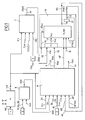
- a rotation speed sensor 1 On each wheel is provided a rotation speed sensor 1, able to output a measure of speed W of rotation of the associated wheel.
- the longitudinal direction is in the front-to-back direction.
- the method according to the invention is implemented in a device, comprising for example one or more digital computers to perform the processing and calculations.
- the longitudinal acceleration Al is provided by measuring a sensor 2 on board the vehicle.
- the traction torque Cmi and the gear ratio Clf, CLr are supplied by a motor calculator (not shown), as is known to those skilled in the art.
- the braking torque Cfij is calculated from the braking pressures Tfij for each wheel, by an estimator 3, for example of the ABS or ESP type.
- the radius R of the turn is calculated from the yaw rate and the steering angle ⁇ of the wheels, that is to say ⁇ d for the right front wheel and ⁇ g for the left front wheel.
- This steering wheel angle ⁇ d , ⁇ g and the yaw rate are measured by onboard sensors on the vehicle.
- the speeds ⁇ ij which are used subsequently have for example been filtered by a low-pass filter.
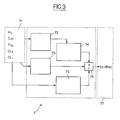
- An estimator 7 is provided for calculating a derivative dSxij of the sliding of the wheel ij from the rotational speed ⁇ ij of the wheel, the engine torque C mi , the braking torque Cfij (or the braking pressure Tfij), the engaged gear ratio CLf, CLr, which form inputs received on an input block 71 of the estimator 7.
- this estimator 7 is described below with reference to the figure 3 .
- Block 72 performs a discrete derivation and filtering of the speed of each wheel and provides an estimate of the acceleration of each wheel.
- Block 73 makes an estimation of the value of the torque applied to each wheel taking into account the braking pressure, the gearbox ratio engaged and the condition of the clutch.
- Block 75 estimates the inertia of the wheels for each of the front and rear axles of the vehicle.
- Block 74 which is connected to block 72, performs a geometric transformation of the estimation of the acceleration of each wheel made by block 72.
- the block 76 performs the estimation of the derivative of the slip of each wheel, from the values estimated by the blocks 74, 75 and 73.
- the acceleration of each wheel is obtained by discrete derivation and filtering of the wheel speed.
- the engine torque applied to each wheel can be obtained from the information from the actuators or by estimation.
- the torque supplied is well controlled and can be estimated thanks to the measurements of electric current and engine speed.
- an estimate of the engine torque gives information on the torque supplied with a medium but sufficient degree of precision.
- the torque at each wheel is calculated taking into consideration the gear ratio or the condition of the clutches (or clutch) between the actuator and the wheels.
- the differential is modeled simply but it is possible to improve the calculation of the torque to the wheel by using a more sophisticated differential model.
- An illustration of the invention consists in calculating the torque at the wheel thanks to the following expression (perfect differential).
- Cf fr Efficiency_Before x P fr
- Cf fl Efficiency_Before x P fl
- Block 74 performs a geometric transformation.
- the computing unit according to the invention can be used to very precisely control including a wheel anti-lock device and / or an anti-skid device of the wheels of a motor vehicle.
- a module 8 is provided for determining a method of calculating the longitudinal velocity of the vehicle for outputting a calculation mode indication MOD signal to an output.
- a module 5 globally represents the entity providing Sl, Sl1, Sl2.
- the front engine is the engine driving the front wheels.
- T mot_AV 0.
- the rear engine is the engine driving the rear wheels.
- T mot_AR 0.
- T mot_AV and T mot_AR are taken into account, as for example in the case of a 4x4 vehicle.
- Threshold word_AV ⁇ min . F z_AV . r
- Threshold mot_AR ⁇ min . F z_AR . r
- Thresholds Threshold word_AV and Threshold word_AV thus chosen represent the minimum motor torques (front or rear) for a coefficient of adhesion ⁇ min .
- the choice of thresholds Seui / mot_AV and Threshold word_AR is to choose the value of ⁇ min .
- an engine torque (front or back) of less than or mot_AV Threshold Threshold mot_AV is insufficient to drag the wheels.
- the speed Vest is generated on an output 6 of the estimator 9 and is furthermore sent to an input 12 of an estimator 10.
- the basic principle of calculating the reference speed Vest is to use the information of the speeds of the wheels that do not slip.
- the longitudinal speed Vest will be estimated by integrating the longitudinal acceleration Al, means being provided for this purpose in the estimator 9.
- a means is also provided, for example in the estimator 9, for providing on an output 19 a signal FIAB indicating reliability of the value V is longitudinal velocity and sliding S xij wheels.
- the signal NF takes the state 1 of unreliability when one does not want to take into account the signal Sxij to detect the sliding of a wheel.
- the drift derivative dS xij is optionally filtered in a bandpass filter. The signal resulting from this bandpass filtering is then used.
- the thresholds dS1, S2, S3, dS4 are prescribed at constant values in the module 10.
- the drift derivative dSxij is sent to the input of a module forming means 101 whose output is connected to a first input 102 of a comparator 103 whose second input 104 is connected to the first threshold dS1.
- the comparator 103 provides on its output 105 a DG1 slip detection signal taking the first slip state 1 in the case where the dSxij module is greater than dS1 and the second non-slip state 0 otherwise.
- dS1 dS4.
- a switching means 107 comprising a switching control input 110 connected to the signal NF, for switching the indicator supply output 111 dij, or on a first input 108 connected to the output 105 when the signal NF is equal at 1, or on a second input 109 when the signal NF is equal to 0.
- the input 109 is connected to the output of an OR logic operator 112, having a first input 113 connected to the output 105, a second input 114 connected to the output of a comparator 116 and a third input 115 connected to the output of a comparator 117.
- the comparator 116 comprises a first input 118 connected to the sliding signal Sxij and a second input 119 connected to the threshold S2, to provide on its output 114 a sliding state 1 when the signal on its first input 118 is greater than the signal on its second input 119, and a state 0 of no slip otherwise.
- the comparator 117 comprises a first input 120 connected to the sliding signal Sxij and a second input 121 connected to the threshold S3, to provide on its output 115 a sliding state 1 when the signal on its first input 120 is greater than the signal on its second input 121, and a state 0 of no slip otherwise.
- the signals Sxij and dSxij used for the slip detection are used.
- the size dSxij is for example filtered in a low-pass filter.
- the logic signal Sl of the braking of the driver is defined as input, which takes the braking value 1 when braking and takes the value 0 otherwise.
- an acceleration utilization signal UTACC is defined for calculating the next state of the indicators dij.
- This UTACC acceleration utilization signal is for example calculated by a module 17, for example of the estimator 10, having as inputs the indicators dij wheels, from the module 15, and 18 output signal UTACC.
- the signal UTACC takes the value 1, or otherwise takes the value 0.
- the reference speed is estimated in the module 9 by integrating the longitudinal acceleration value A1 supplied by the sensor 2, the module 9 comprising for this purpose an integrating module receiving this longitudinal acceleration Al.
- the indicator dij is rehabilitated in the state 0 of no slip in the following manner.
- each threshold on the modules or absolute values may include a positive threshold for the positive values and a negative threshold for the negative values.
- the input 205 is connected to the output of a switch 206 having a switching control input 207 connected to the braking signal Sl for switching the input 205, or on a first input 208 of the switch 206 in the case where the signal SL is at 1 in the presence of a braking of the driver, or on a second input 209 of the switch 206 in the case where the signal SL is at 0 in the absence of driver braking.
- the input 208 is connected to a RV signal of rehabilitation on the speed.
- the input 209 is connected to the output of an AND logic operator 210, having a first input 211 connected to the state output Q of an RS type flip-flop 213 and a second input 212 connected to the output of a
- the comparator 214 comprises a first input 217 connected to the output of an operator 218 forming the absolute value of the sliding signal Sxij applied to its input 14 and a second input 219 connected to the threshold S13.
- Inputs 204 and 216 are connected to a rehabilitation condition signal COND on dSxij.
- the output of the comparator 214 provides on the input 212 as well as on a branch 220 thereof a correction indication signal Sxc, which is equal to 1 when the value on the input 217 is less than or equal to the value on entry 219, which is equal to 0 otherwise.
- a means 221 for producing, on an output 222, the signal RV of rehabilitation on the speed comprises a logic AND operator 223 comprising a first input 224 connected to the signal Sxc and a second input 225 connected to the output of a delay unit 226 receiving on its input 227 the indicator dij.
- the output 228 of the logical operator ET 223 is connected to the input of a logical NOT operator 229 whose output is connected to a first input 230 of reset of an integrator 231 in discrete time, in order to reset zero the value present on the output 232 thereof when the input 230 is 1.
- the integrator 231 has a second signal input 233 to integrate, connected to the output of an operator 234 inverter of the present value on its input 235, itself connected to the duration T11, in order to supply at the end of this duration T11 a signal equal to 1 on the output 232 since the value present on the first input 230 is equal to 0.
- the output 232 is connected to a first input of a logic operator 236 of equality receiving on a second input 237 a constant value C1, equal to 1 in the previous example, to provide on the output 222 the signal RV of rehabilitation on the speed, which is equal to 1 in case of equality between the value present on the first input 232 and the value C1 present on the second input 237, and a value 0 otherwise.
- a means 241 for producing the conditional condition signal COND on the derivative of the slip comprises an integrator 242 of the same type as the integrator 231 described with reference to FIG. figure 7 , whose first reset input is designated 243, the second signal input to be integrated by 244, the output by 245, itself connected to the first input of a logic operator 246 equal of the same type as the operator 236 and having on its second input 247 a constant C2 for example equal to 1, this operator 246 providing on its output 248 the signal COND.
- the first input 243 is connected to the output of a logic operator NO 249, whose input 250 is connected to the output of an AND logic operator 251.
- the AND operator 251 comprises a first input 252 connected to the output of FIG.
- a comparator 253 which has a first input 254 connected by an operator 255 for forming the absolute value to an input 256 connected to the drift derivative signal dSxij, and a second input 257 connected to the threshold dS12.
- the AND operator 251 also has a second input 258 connected to the output of a delay unit 259, whose input 260 is connected to the indicator dij.
- the second signal input 244 of integration integrator 242 is connected to the output of an inverse value forming operator 261 whose input 262 is connected to the output of a switch 263.
- switching control input 264 connected to the braking signal Sl, for switching the output 262, either on a first input 265 connected to the duration T122 when the driver brakes when the signal S1 is equal to 1, or on a second input 266 connected to the duration T121 in the absence of braking of the driver when the signal Sl is equal to 0.
Claims (20)
- Verfahren zum Schätzen einer Referenzgeschwindigkeit eines Kraftfahrzeugs auf Rädern mit Hilfe eines Rechners an Bord des Fahrzeugs, wobei durch wenigstens einen Sensor (1) die Drehgeschwindigkeit (Wij) jedes Rades (ij) des Fahrzeugs gemessen wird, wobei eine longitudinale Verlagerungsgeschwindigkeit (Vest) des Fahrzeugs erhalten wird,
dadurch gekennzeichnet, dass
für jedes Rad der Schlupf (Sxij) des Rades anhand der Drehgeschwindigkeit (Wij) des Rades und der erhaltenen longitudinalen Verlagerungsgeschwindigkeit (Vest) berechnet wird,
für jedes Rad anhand wenigstens der gemessenen Drehgeschwindigkeit (Wij) des Rades und wenigstens einer anderen Größe eine Ableitung (dSxij) des Rades berechnet wird,
ein Unzuverlässigkeitssignal (NF) der Schlupfe der Räder berechnet wird, das einen ersten Zustand (NF = 1) fehlender Zuverlässigkeit in dem Fall annimmt, in dem für alle Räder ein Schlupfindikator (dij) in einem ersten Zustand (dij = 1) mit Schlupf ist, und andernfalls wenigstens einen zweiten Zustand annimmt,- in dem Fall, in dem das Unzuverlässigkeitssignal (NF) in dem zweiten Zustand ist, für jedes Rad der Radschlupfindikator (dij) den ersten Zustand (dij = 1) mit Schlupf annimmt, wenn die Ableitung (dSxij) des Radschlupfes größer als ein erster, vorgeschriebener, positiver Schwellenwert (dS1) ist oder wenn die Ableitung (dSxij) des Radschlupfes kleiner als ein zweiter, vorgeschriebener, negativer Schwellenwert (dS1) ist oder wenn der Schlupf (Sxij) des Rades größer als ein dritter, vorgeschriebener, positiver Schwellenwert (S2) ist oder wenn der Schlupf (Sxij) des Rades kleiner als ein vierter, vorgeschriebener, negativer Schwellenwert (S3) ist, und andernfalls einen zweiten Zustand (dij = 0) ohne Radschlupf annimmt,- in dem Fall, in dem das Unzuverlässigkeitssignal (NF) in dem ersten Zustand (NF = 1) ist, der Indikator (dij) des Radschlupfes den ersten Zustand (dij = 1) mit Schlupf annimmt, wenn die Ableitung (dSxij) des Radschlupfes größer als ein fünfter, vorgeschriebener, positiver Schwellenwert (dS4) ist oder wenn die Ableitung (dSxij) des Radschlupfes kleiner als ein sechster, vorgeschriebener, negativer Schwellenwert (dS4) ist. - Schätzverfahren nach Anspruch 1, dadurch gekennzeichnet, dass von wenigstens einem Organ für die Betätigung der Bremse durch den Fahrer ein Bremsangabesignal (SI) erhalten wird, das in einem ersten Zustand mit Bremsen oder in einem zweiten Zustand ohne Bremsen sein kann,
der Radschlupfindikator (dij) von seinem ersten Zustand mit Schlupf wieder in seinen zweiten Zustand ohne Schlupf versetzt wird, wenn während einer vorgeschriebenen ersten Dauer (T11) zugleich alle Radschlupfindikatoren (dij) nicht im ersten Zustand (dij = 1) mit Schlupf sind, das Bremssignal (SI) im ersten Zustand mit Bremsen ist und der zugeordnete Schlupf (Sxij) kleiner als ein siebter, vorgeschriebener, positiver Schwellenwert (S11) und größer als ein achter, vorgeschriebener, negativer Schwellenwert (S11) ist. - Schätzverfahren nach einem der vorhergehenden Ansprüche, dadurch gekennzeichnet, dass von wenigstens einem Organ für die Betätigung der Bremse durch den Fahrer ein Bremsangabesignal (SI) erhalten wird, das in einem ersten Zustand mit Bremsen oder in einem zweiten Zustand ohne Bremsen sein kann,
der Radschlupfindikator (dij) von seinem ersten Zustand mit Schlupf wieder in seinen zweiten Zustand ohne Schlupf versetzt wird, wenn während einer zweiten Dauer (T121) zugleich alle Radschlupfindikatoren (dij) nicht im ersten Zustand (dij = 1) mit Schlupf sind, das Bremssignal (SI) im zweiten Zustand ohne Bremsdetektion (SI = 0) ist, die Ableitung (dSxij) des Schlupfes kleiner als ein neunter, vorgeschriebener, positiver Schwellenwert (dS12) und größer als ein zehnter, vorgeschriebener, negativer Schwellenwert (dS12) ist und wenn am Ende der zweiten Dauer (T121) der Schlupf (Sxij) kleiner als ein elfter, vorgeschriebener, positiver Schwellenwert (S13) und größer als ein zwölfter, vorgeschriebener, negativer Schwellenwert (S13) ist. - Schätzverfahren nach einem der vorhergehenden Ansprüche, dadurch gekennzeichnet, dass von wenigstens einem Organ für die Betätigung der Bremse durch den Fahrer ein Bremsangabesignal (SI) erhalten wird, das in einem ersten Zustand mit Bremsen oder in einem zweiten Zustand ohne Bremsen sein kann,
der Radschlupfindikator (dij) von seinem ersten Zustand mit Schlupf wieder in seinen zweiten Zustand ohne Schlupf versetzt wird, wenn während einer dritten vorgeschriebenen Dauer (T122) zugleich alle Radschlupfindikatoren (dij) im ersten Zustand (dij = 1) mit Schlupf sind, das Bremssignal (SI) im ersten Zustand mit Bremsdetektion ist und die Ableitung (dSxij) des Schlupfes kleiner als ein dreizehnter, vorgeschriebener, positiver Schwellenwert (dS12) und größer als ein vierzehnter, vorgeschriebener, negativer Schwellenwert (dS12) ist. - Schätzverfahren nach einem der vorhergehenden Ansprüche, dadurch gekennzeichnet, dass von wenigstens einem Organ für die Betätigung der Bremse durch den Fahrer ein Bremsangabesignal (SI) erhalten wird, das in einem ersten Zustand mit Bremsen oder in einem zweiten Zustand ohne Bremsen sein kann,
der Radschlupfindikator (dij) von seinem ersten Zustand mit Schlupf wieder in seinen zweiten Zustand ohne Schlupf versetzt wird, wenn während einer zweiten Dauer (T121) zugleich alle Radschlupfindikatoren (dij) im ersten Zustand mit Schlupf sind, das Bremssignal (SI) im zweiten Zustand ohne Bremsdetektion ist, die Ableitung (dSxij) des Schlupfes kleiner als ein fünfzehnter, vorgeschriebener, positiver Schwellenwert (dS12) und größer als ein sechzehnter, vorgeschriebener, negativer Schwellenwert (dS12) ist. - Verfahren nach einem der vorhergehenden Ansprüche, dadurch gekennzeichnet, dass die Berechnung der Ableitung (dSxij) des Schlupfes die folgenden Schritte umfasst:g) Erfassen von Daten bezüglich der Drehgeschwindigkeit der Räder, der an die Räder angelegten Motordrehmomente, der Bremsdrücke und des eingelegten Getriebeübersetzungsverhältnisses,h) Schätzen der Beschleunigung jedes Rades durch Ausführen eine diskreten Ableitung und einer Filterung der Drehgeschwindigkeit jedes Rades,i) Schätzen des an jedes Rad angelegten Drehmoments unter Berücksichtigung des Bremsdrucks, des eingelegten Getriebeübersetzungsverhältnisses und des Kupplungszustandes,j) Schätzen der Trägheit der Räder sowohl für die Vorderachse als auch für die Hinterachse des Fahrzeugs,k) Ausführen einer geometrischen Transformation der Schätzung der Beschleunigung jedes Rades, die in b) geschätzt wird,l) Schätzen der Ableitung des Schlupfes jedes Rades anhand der Werte, die in c), d) und e) geschätzt werden.
- Verfahren nach einem der vorhergehenden Ansprüche, dadurch gekennzeichnet, dass die Berechnung des Schlupfes (Sxij) des Rades durch Multiplizieren der Drehgeschwindigkeit (ωij) des Rades mit seinem Radius, was die Lineargeschwindigkeit (Vij) des Rades ergibt, und dann durch Subtraktion der somit erhaltenen Lineargeschwindigkeit von der erhaltenen longitudinalen Verlagerungsgeschwindigkeit (Vest) erhalten wird.
- Verfahren nach einem der vorhergehenden Ansprüche, dadurch gekennzeichnet, dass die longitudinale Verlagerungsgeschwindigkeit (Vest) des Fahrzeugs durch Berechnen anhand der gemessenen Raddrehgeschwindigkeiten (Wij), für die der Indikator (dij) des Radschlupfes im zweiten Zustand (dij = 0) ohne Radschlupf ist, ohne die gemessenen Raddrehgeschwindigkeiten (Wij) zu berücksichtigen, für die der Indikator (dij) des Radschlupfes im ersten Zustand (dij = 1) mit Schlupf ist, erhalten wird.
- Verfahren nach einem der vorhergehenden Ansprüche, dadurch gekennzeichnet, dass in dem Fall, in dem der Schlupfindikator (dij) aller Räder im ersten Zustand (dij = 1) mit Schlupf ist, die longitudinale Verlagerungsgeschwindigkeit (Vest) des Fahrzeugs durch Integration einer longitudinalen Beschleunigung (Al), die durch einen Längsbeschleunigungssensor (2) gemessen wird, erhalten wird.
- Verfahren nach einem der vorhergehenden Ansprüche, dadurch gekennzeichnet, dass von wenigstens einem Organ für die Betätigung der Bremse durch den Fahrer ein Bremsangabesignal (SI) erhalten wird, das in einem ersten Zustand mit Bremsen oder in einem zweiten Zustand ohne Bremsen sein kann,
dann, wenn zugleich der Schlupf eines Rades negativ ist und das Bremsangabesignal (SI) im ersten Zustand mit Bremsen ist, die longitudinale Verlagerungsgeschwindigkeit (Vest) des Fahrzeugs anhand der größten Raddrehgeschwindigkeit erhalten wird. - Verfahren nach einem der vorhergehenden Ansprüche, dadurch gekennzeichnet, dass von wenigstens einem Organ für die Betätigung der Bremse durch den Fahrer ein Bremsangabesignal (SI) erhalten wird, das in einem ersten Zustand mit Bremsen oder in einem zweiten Zustand ohne Bremsen sein kann,
dann, wenn zugleich der Schlupf eines Rades positiv ist und das Bremsangabesignal (SI) im zweiten Zustand ohne Bremsen ist, die longitudinale Verlagerungsgeschwindigkeit (Vest) des Fahrzeugs anhand der kleinsten Raddrehgeschwindigkeit erhalten wird. - Verfahren nach einem der vorhergehenden Ansprüche, dadurch gekennzeichnet, dass
ein Drehmomentwert (Cmi) des oder der Motoren an den Vorderrädern und/oder den Hinterrädern erhalten wird,
mehrere Arten (MOD) für die Berechnung der longitudinalen Verlagerungsgeschwindigkeit (Vest) des Fahrzeugs definiert sind:- eine erste Berechnungsart (MOD = 2), wenn zugleich das Drehmoment an den Vorderrädern kleiner als ein erster, vorgeschriebener, positiver Schwellenwert und größer als ein zweiter, vorgeschriebener, negativer Schwellenwert ist und das Drehmoment an den Hinterrädern größer als ein dritter, vorgeschriebener, positiver Schwellenwert oder kleiner als ein vierter, vorgeschriebener, negativer Schwellenwert ist,- eine zweite Berechnungsart (MOD = 3), wenn zugleich das Drehmoment an den Hinterrädern kleiner als ein fünfter, vorgeschriebener, positiver Schwellenwert und größer als ein sechster, vorgeschriebener, negativer Schwellenwert ist und das Drehmoment an den Vorderrädern größer als ein siebter, vorgeschriebener, positiver Schwellenwert oder kleiner als ein achter, vorgeschriebener, negativer Schwellenwert ist,- eine dritte Berechnungsart (MOD = 1), wenn die Bedingungen, die der ersten und der zweiten Berechnungsart entsprechen, nicht erfüllt sind. - Verfahren nach Anspruch 12, dadurch gekennzeichnet, dass- in der ersten Berechnungsart (MOD = 2) die longitudinale Verlagerungsgeschwindigkeit (Vest) des Fahrzeugs berechnet wird:· anhand der Drehgeschwindigkeit der Vorderräder, deren Schlupfindikator (dij) im zweiten Zustand (dij = 0) ohne Schlupf ist, oder· anhand der Drehgeschwindigkeit der Hinterräder, die sich im zweiten Zustand (dij = 0) ohne Schlupf befinden, falls alle Vorderräder einen Schlupfindikator besitzen, der im ersten Zustand mit Schlupf ist.
- Verfahren nach einem der Ansprüche 12 und 13, dadurch gekennzeichnet, dass- in der zweiten Berechnungsart (MOD = 3) die longitudinale Verlagerungsgeschwindigkeit (Vest) des Fahrzeugs berechnet wird:· anhand der Drehgeschwindigkeit der Hinterräder, deren Schlupfindikator (dij) im zweiten Zustand (dij = 0) ohne Schlupf ist, oder· anhand der Drehgeschwindigkeit der Vorderräder, die sich im zweiten Zustand (dij = 0) ohne Schlupf befinden, falls alle Hinterräder einen Schlupfindikator haben, der im ersten Zustand mit Schlupf ist.
- Verfahren nach einem der Ansprüche 12 bis 14, dadurch gekennzeichnet, dass- in der dritten Berechnungsart (MOD = 1) die longitudinale Verlagerungsgeschwindigkeit (Vest) des Fahrzeugs anhand der Drehgeschwindigkeit der Hinterräder und der Vorderräder, die im zweiten Zustand (dij = 0) ohne Schlupf sind, berechnet wird.
- Verfahren nach einem der Ansprüche 12 bis 15, dadurch gekennzeichnet, dass
wenigstens von einem Organ für die Betätigung der Bremse durch den Fahrer ein erstes Bremsangabesignal (SI) erhalten wird, das in einem ersten Zustand mit Bremsen oder in einem zweiten Zustand ohne Bremsen sein kann, und
um die Bedingungen der ersten und der zweiten Berechnungsart zu erfüllen, das erste Signal (SI) für die Angabe eines Bremsens durch den Fahrer außerdem im zweiten Zustand ohne Bremsen sein muss. - Verfahren nach einem der Ansprüche 12 bis 16, dadurch gekennzeichnet, dass
anhand eines Bremsregulierungssystems an den Vorderrädern und an den Hinterrädern wenigstens ein zweites Signal (SI2) für die Angabe eines Bremsens an den Vorderrädern, das in einem ersten Zustand mit Bremsen oder in einem zweiten Zustand ohne Bremsen sein kann, und wenigstens ein drittes Signal (SI3) für die Angabe des Bremsens an den Hinterrädern, das in einem ersten Zustand mit Bremsen oder in einem zweiten Zustand ohne Bremsen sein kann, erhalten werden,- um die Bedingungen der ersten Berechnungsart (MOD = 2) zu erfüllen, zugleich das Drehmoment an den Vorderrädern kleiner als ein erster, vorgeschriebener, positiver Schwellenwert und größer als ein zweiter, vorgeschriebener, negativer Schwellenwert ist, das zweite Signal (SI2) für die Angabe des Bremsens an den Vorderrädern im zweiten Zustand ohne Bremsen ist, das Drehmoment an den Hinterrädern größer als ein dritter, vorgeschriebener, positiver Schwellenwert oder kleiner als ein vierter, vorgeschriebener, negativer Schwellenwert ist oder das dritte Signal (SI3) für die Angabe des Bremsens an den Hinterrädern in dem ersten Zustand mit Bremsen ist,- um die Bedingungen der zweiten Berechnungsart (MOD = 3) zu erfüllen, zugleich das Drehmoment an den Hinterrädern kleiner als ein fünfter, vorgeschriebener, positiver Schwellenwert und größer als ein sechster, vorgeschriebener negativer Schwellenwert ist, das dritte Signal (SI3) für die Angabe des Bremsens an den Hinterrädern in dem zweiten Zustand ohne Bremsen ist, das Drehmoment an den Vorderrädern größer als ein siebter, vorgeschriebener, positiver Schwellenwert oder kleiner als ein achter, vorgeschriebener, negativer Schwellenwert ist oder das zweite Signal (SI2) für die Angabe des Bremsens an den Vorderrädern in dem ersten Zustand mit Bremsen ist. - Verfahren nach einem der Ansprüche 12 bis 17, dadurch gekennzeichnet, dass die Schwellenwerte proportional zu einer vorgegebenen Gewichtsverteilung des Fahrzeugs an wenigstens einer Vorderachse, die die Vorderräder trägt, und an wenigstens einer Hinterachse, die die Hinterräder trägt, festgelegt sind.
- Verfahren nach einem der Ansprüche 12 bis 18, dadurch gekennzeichnet, dass der arithmetische Mittelwert der Raddrehgeschwindigkeiten, die in den Berechnungsarten gehalten werden, gebildet wird und mit einem vorgeschriebenen Radius des Rades multipliziert wird, um die longitudinale Verlagerungsgeschwindigkeit (Vest) des Fahrzeugs zu berechnen.
- Vorrichtung für die Ausführung des Verfahrens nach einem der vorhergehenden Ansprüche, die dazu vorgesehen ist, an Bord eines Kraftfahrzeugs auf Rädern angeordnet zu sein, dadurch gekennzeichnet, dass sie umfasst:wenigstens einen Sensor (1) für die Drehgeschwindigkeit (Wij) jedes Rades (ij) des Fahrzeugs,ein Mittel (9) zum Erhalten einer longitudinalen Verlagerungsgeschwindigkeit (Vest) des Fahrzeugs,ein Mittel (11) zum Berechnen des Schlupfes (Sxij) jedes Rades anhand der Drehgeschwindigkeit (Wij) des Rades und der erhaltenen longitudinalen Verlagerungsgeschwindigkeit (Vest),ein Mittel (7) zum Berechnen einer Ableitung (dSxij) des Radschlupfs wenigstens anhand der gemessenen Drehgeschwindigkeit (Wij) des Rades und wenigstens einer anderen Größe für jedes Rad,ein Mittel (9) zum Berechnen eines Unzuverlässigkeitssignals (NF) der Schlupfe der Räder, das einen ersten Zustand (NF = 1) fehlender Zuverlässigkeit in dem Fall annimmt, in dem für alle Räder ein Schlupfindikator (dij) in einem ersten Zustand (dij = 1) mit Schlupf ist, und andernfalls wenigstens einen zweiten Zustand annimmt,ein Mittel (15) zum Erzeugen des Schlupfindikators (dij) für jedes Rad, damit- in dem Fall, in dem das Unzuverlässigkeitssignal (NF) im zweiten Zustand ist, der Radschlupfindikator (dij) den ersten Zustand (dij = 1) mit Schlupf annimmt, wenn die Ableitung (dSxij) des Radschlupfs größer als ein erster, vorgeschriebener, positiver Schwellenwert (dS1) ist oder wenn die Ableitung (dSxij) des Radschlupfs kleiner als ein zweiter, vorgeschriebener, negativer Schwellenwert (dS1) ist oder wenn der Schlupf (Sxij) des Rades größer als ein dritter, vorgeschriebener, positiver Schwellenwert (S2) ist oder wenn der Schlupf (Sxij) des Rades kleiner als ein vierter, vorgeschriebener, negativer Schwellenwert (S3) ist, und andernfalls einen zweiten Zustand (dij = 0) ohne Radschlupf annimmt,- in dem Fall, in dem das Unzuverlässigkeitssignal (NF) in dem ersten Zustand (NF = 1) ist, der Radschlupfindikator (dij) den ersten Zustand (dij = 1) mit Schlupf annimmt, wenn die Ableitung (dSxij) des Radschlupfes größer als ein fünfter, vorgeschriebener, positiver Schwellenwert (dS4) ist oder wenn die Ableitung (dSxij) des Radschlupfes kleiner als ein sechster, vorgeschriebener, negativer Schwellenwert (dS4) ist.
Applications Claiming Priority (2)
| Application Number | Priority Date | Filing Date | Title |
|---|---|---|---|
| FR0705739A FR2919930B1 (fr) | 2007-08-06 | 2007-08-06 | Procede d'estimation de la vitesse longitudinale d'un vehicule et dispositif pour sa mise en oeuvre |
| PCT/FR2008/051371 WO2009019392A2 (fr) | 2007-08-06 | 2008-07-21 | Procede d ' estimation du glissement des roues d ' un vehicule et dispositif pour sa mise en oeuvre |
Publications (2)
| Publication Number | Publication Date |
|---|---|
| EP2176111A2 EP2176111A2 (de) | 2010-04-21 |
| EP2176111B1 true EP2176111B1 (de) | 2011-09-07 |
Family
ID=39272461
Family Applications (1)
| Application Number | Title | Priority Date | Filing Date |
|---|---|---|---|
| EP08827167A Not-in-force EP2176111B1 (de) | 2007-08-06 | 2008-07-21 | Verfahren zur schätzung des gleitverhaltens der räder eines fahrzeugs und vorrichtung zur anwendung dieses verfahrens |
Country Status (4)
| Country | Link |
|---|---|
| EP (1) | EP2176111B1 (de) |
| AT (1) | ATE523404T1 (de) |
| FR (1) | FR2919930B1 (de) |
| WO (1) | WO2009019392A2 (de) |
Cited By (1)
| Publication number | Priority date | Publication date | Assignee | Title |
|---|---|---|---|---|
| EP3900990B1 (de) * | 2018-12-18 | 2024-02-07 | NISSAN MOTOR Co., Ltd. | Verfahren zur schätzung der fahrzeuggeschwindigkeit und vorrichtung zur schätzung der fahrzeuggeschwindigkeit für ein allradantriebsfahrzeug |
Family Cites Families (6)
| Publication number | Priority date | Publication date | Assignee | Title |
|---|---|---|---|---|
| DE3545012A1 (de) * | 1985-12-19 | 1987-07-02 | Audi Ag | Verfahren zur schlupferkennung |
| ES2013741B3 (es) * | 1986-07-11 | 1990-06-01 | Audi Ag | Procedimiento para controlar el resbalamiento |
| DE3722049A1 (de) * | 1986-07-11 | 1988-02-04 | Audi Ag | Verfahren zum erfassen des schlupfzustandes |
| DE102004040757A1 (de) * | 2003-12-12 | 2005-07-28 | Continental Teves Ag & Co. Ohg | Verfahren zur Ermittlung der Fahrzeugreferenzgeschwindigkeit für Allradfahrzeuge mit einer Motorschleppmomentenregelung und einer elektronisch gesteuerten Mittenkupplung |
| DE102005053666A1 (de) * | 2005-11-10 | 2007-05-16 | Hella Kgaa Hueck & Co | Verfahren und Vorrichtung zur Korrektur einer Fahrzeuggeschwindigkeit |
| FR2896467B1 (fr) * | 2006-01-20 | 2008-03-07 | Renault Sas | Procede d'estimation de la vitesse longitudinale d'un vehicule automobile |
-
2007
- 2007-08-06 FR FR0705739A patent/FR2919930B1/fr not_active Expired - Fee Related
-
2008
- 2008-07-21 AT AT08827167T patent/ATE523404T1/de not_active IP Right Cessation
- 2008-07-21 WO PCT/FR2008/051371 patent/WO2009019392A2/fr active Application Filing
- 2008-07-21 EP EP08827167A patent/EP2176111B1/de not_active Not-in-force
Cited By (1)
| Publication number | Priority date | Publication date | Assignee | Title |
|---|---|---|---|---|
| EP3900990B1 (de) * | 2018-12-18 | 2024-02-07 | NISSAN MOTOR Co., Ltd. | Verfahren zur schätzung der fahrzeuggeschwindigkeit und vorrichtung zur schätzung der fahrzeuggeschwindigkeit für ein allradantriebsfahrzeug |
Also Published As
| Publication number | Publication date |
|---|---|
| FR2919930B1 (fr) | 2009-10-02 |
| WO2009019392A2 (fr) | 2009-02-12 |
| EP2176111A2 (de) | 2010-04-21 |
| WO2009019392A3 (fr) | 2009-03-26 |
| FR2919930A1 (fr) | 2009-02-13 |
| ATE523404T1 (de) | 2011-09-15 |
Similar Documents
| Publication | Publication Date | Title |
|---|---|---|
| EP3452792B1 (de) | Verfahren und vorrichtung zur bestimmung einer schätzung der gesamtmasse eines kraftfahrzeugs | |
| EP1642096B1 (de) | Verfahren und einrichtung zur schätzung der gesamtmasse eines kraftfahrzeugs | |
| EP3030449B1 (de) | Regelung der regenerativen bremsung in einem elektro- oder hybridfahrzeug | |
| EP2758257B1 (de) | Verfahren zur schätzung des rollwiderstandes eines fahrzeugrades | |
| EP2855228A1 (de) | Verfahren zur detektion einer frühzeitigen beschleunigung eines kraftfahrzeugs | |
| EP2176110B1 (de) | Verfahren zur schätzung der langfristigen geschwindigkeit eines fahrzeugs und vorrichtung zur anwendung dieses verfahrens | |
| EP2176111B1 (de) | Verfahren zur schätzung des gleitverhaltens der räder eines fahrzeugs und vorrichtung zur anwendung dieses verfahrens | |
| EP2307253B1 (de) | Vorrichtung zur bestimmung der querbeschleunigung eines motorfahrzeugs und entsprechendes verfahren | |
| FR2902048A1 (fr) | Systeme et procede de commande des efforts appliques aux trains avant et arriere d'un vehicule automobile hybride a quatre roues motrices | |
| EP1940662B1 (de) | Verfahren zur bestimmung des zustandes von kraftfahrzeugreifen und vorrichtung dafür | |
| FR2932878A1 (fr) | Dispositif et procede de l'estimation de la pente du terrain pour le roulage d'un vehicule automobile. | |
| EP1996437B1 (de) | Verfahren zum schätzen der ableitung eines kraftfahrzeugradschlupfes und recheneinheit zur durchführung der schätzung | |
| EP1538042B1 (de) | System und Verfahren zur Steuerung der Beschleunigung eines Kraftfahrzeugs an einem Gefälle | |
| FR2903063A1 (fr) | Procede de detection du glissement d'une roue de vehicule automobile. | |
| FR2906518A1 (fr) | Procede de detection de reprise d'adherence d'une roue de vehicule automobile. | |
| FR2922026A3 (fr) | Procede d'estimation de la vitesse longitudinale d'un vehicule automobile | |
| FR2932892A1 (fr) | Dispositif et procede d'estimation de la vitesse d'un vehicule. | |
| FR2921036A1 (fr) | Procede d'estimation d'un coefficient d'adherence d'une roue par rapport au sol | |
| FR2988645A1 (fr) | Procede d'estimation de la resistance au roulement de roues equipant un train d'un vehicule | |
| FR2994897A1 (fr) | Procede de gestion du glissement d'une roue motrice d'un vehicule automobile | |
| EP1522861A1 (de) | Verfahren zur Ermittlung der Lineargeschwindigkeit eines Fahrzeuges aus Vertikalbewegungen der Räder, sowie Fahrzeug mit einer solchen Messvorrichtung | |
| FR2979077A1 (fr) | Procede d'estimation de la resistance au roulement d'une roue de vehicule automobile et dispositif pour mettre en oeuvre ce procede. | |
| FR2922653A1 (fr) | Procede d'estimation de la vitesse longitidinale d'un vehicule automobile. | |
| FR2972411A3 (fr) | Procede de freinage a partir d'un indicateur de stabilite d'un vehicule |
Legal Events
| Date | Code | Title | Description |
|---|---|---|---|
| PUAI | Public reference made under article 153(3) epc to a published international application that has entered the european phase |
Free format text: ORIGINAL CODE: 0009012 |
|
| 17P | Request for examination filed |
Effective date: 20100129 |
|
| AK | Designated contracting states |
Kind code of ref document: A2 Designated state(s): AT BE BG CH CY CZ DE DK EE ES FI FR GB GR HR HU IE IS IT LI LT LU LV MC MT NL NO PL PT RO SE SI SK TR |
|
| AX | Request for extension of the european patent |
Extension state: AL BA MK RS |
|
| GRAP | Despatch of communication of intention to grant a patent |
Free format text: ORIGINAL CODE: EPIDOSNIGR1 |
|
| DAX | Request for extension of the european patent (deleted) | ||
| GRAS | Grant fee paid |
Free format text: ORIGINAL CODE: EPIDOSNIGR3 |
|
| GRAA | (expected) grant |
Free format text: ORIGINAL CODE: 0009210 |
|
| REG | Reference to a national code |
Ref country code: GB Ref legal event code: FG4D Free format text: NOT ENGLISH |
|
| REG | Reference to a national code |
Ref country code: CH Ref legal event code: EP |
|
| REG | Reference to a national code |
Ref country code: IE Ref legal event code: FG4D Free format text: LANGUAGE OF EP DOCUMENT: FRENCH |
|
| REG | Reference to a national code |
Ref country code: DE Ref legal event code: R096 Ref document number: 602008009643 Country of ref document: DE Effective date: 20111201 |
|
| REG | Reference to a national code |
Ref country code: NL Ref legal event code: VDEP Effective date: 20110907 |
|
| PG25 | Lapsed in a contracting state [announced via postgrant information from national office to epo] |
Ref country code: SE Free format text: LAPSE BECAUSE OF FAILURE TO SUBMIT A TRANSLATION OF THE DESCRIPTION OR TO PAY THE FEE WITHIN THE PRESCRIBED TIME-LIMIT Effective date: 20110907 Ref country code: NO Free format text: LAPSE BECAUSE OF FAILURE TO SUBMIT A TRANSLATION OF THE DESCRIPTION OR TO PAY THE FEE WITHIN THE PRESCRIBED TIME-LIMIT Effective date: 20111207 Ref country code: LT Free format text: LAPSE BECAUSE OF FAILURE TO SUBMIT A TRANSLATION OF THE DESCRIPTION OR TO PAY THE FEE WITHIN THE PRESCRIBED TIME-LIMIT Effective date: 20110907 Ref country code: FI Free format text: LAPSE BECAUSE OF FAILURE TO SUBMIT A TRANSLATION OF THE DESCRIPTION OR TO PAY THE FEE WITHIN THE PRESCRIBED TIME-LIMIT Effective date: 20110907 Ref country code: HR Free format text: LAPSE BECAUSE OF FAILURE TO SUBMIT A TRANSLATION OF THE DESCRIPTION OR TO PAY THE FEE WITHIN THE PRESCRIBED TIME-LIMIT Effective date: 20110907 |
|
| LTIE | Lt: invalidation of european patent or patent extension |
Effective date: 20110907 |
|
| PG25 | Lapsed in a contracting state [announced via postgrant information from national office to epo] |
Ref country code: CY Free format text: LAPSE BECAUSE OF FAILURE TO SUBMIT A TRANSLATION OF THE DESCRIPTION OR TO PAY THE FEE WITHIN THE PRESCRIBED TIME-LIMIT Effective date: 20110907 Ref country code: AT Free format text: LAPSE BECAUSE OF FAILURE TO SUBMIT A TRANSLATION OF THE DESCRIPTION OR TO PAY THE FEE WITHIN THE PRESCRIBED TIME-LIMIT Effective date: 20110907 Ref country code: LV Free format text: LAPSE BECAUSE OF FAILURE TO SUBMIT A TRANSLATION OF THE DESCRIPTION OR TO PAY THE FEE WITHIN THE PRESCRIBED TIME-LIMIT Effective date: 20110907 Ref country code: GR Free format text: LAPSE BECAUSE OF FAILURE TO SUBMIT A TRANSLATION OF THE DESCRIPTION OR TO PAY THE FEE WITHIN THE PRESCRIBED TIME-LIMIT Effective date: 20111208 Ref country code: SI Free format text: LAPSE BECAUSE OF FAILURE TO SUBMIT A TRANSLATION OF THE DESCRIPTION OR TO PAY THE FEE WITHIN THE PRESCRIBED TIME-LIMIT Effective date: 20110907 |
|
| REG | Reference to a national code |
Ref country code: AT Ref legal event code: MK05 Ref document number: 523404 Country of ref document: AT Kind code of ref document: T Effective date: 20110907 |
|
| REG | Reference to a national code |
Ref country code: IE Ref legal event code: FD4D |
|
| PG25 | Lapsed in a contracting state [announced via postgrant information from national office to epo] |
Ref country code: SK Free format text: LAPSE BECAUSE OF FAILURE TO SUBMIT A TRANSLATION OF THE DESCRIPTION OR TO PAY THE FEE WITHIN THE PRESCRIBED TIME-LIMIT Effective date: 20110907 Ref country code: IE Free format text: LAPSE BECAUSE OF FAILURE TO SUBMIT A TRANSLATION OF THE DESCRIPTION OR TO PAY THE FEE WITHIN THE PRESCRIBED TIME-LIMIT Effective date: 20110907 Ref country code: IS Free format text: LAPSE BECAUSE OF FAILURE TO SUBMIT A TRANSLATION OF THE DESCRIPTION OR TO PAY THE FEE WITHIN THE PRESCRIBED TIME-LIMIT Effective date: 20120107 Ref country code: CZ Free format text: LAPSE BECAUSE OF FAILURE TO SUBMIT A TRANSLATION OF THE DESCRIPTION OR TO PAY THE FEE WITHIN THE PRESCRIBED TIME-LIMIT Effective date: 20110907 |
|
| PG25 | Lapsed in a contracting state [announced via postgrant information from national office to epo] |
Ref country code: NL Free format text: LAPSE BECAUSE OF FAILURE TO SUBMIT A TRANSLATION OF THE DESCRIPTION OR TO PAY THE FEE WITHIN THE PRESCRIBED TIME-LIMIT Effective date: 20110907 Ref country code: RO Free format text: LAPSE BECAUSE OF FAILURE TO SUBMIT A TRANSLATION OF THE DESCRIPTION OR TO PAY THE FEE WITHIN THE PRESCRIBED TIME-LIMIT Effective date: 20110907 Ref country code: EE Free format text: LAPSE BECAUSE OF FAILURE TO SUBMIT A TRANSLATION OF THE DESCRIPTION OR TO PAY THE FEE WITHIN THE PRESCRIBED TIME-LIMIT Effective date: 20110907 Ref country code: PL Free format text: LAPSE BECAUSE OF FAILURE TO SUBMIT A TRANSLATION OF THE DESCRIPTION OR TO PAY THE FEE WITHIN THE PRESCRIBED TIME-LIMIT Effective date: 20110907 Ref country code: IT Free format text: LAPSE BECAUSE OF FAILURE TO SUBMIT A TRANSLATION OF THE DESCRIPTION OR TO PAY THE FEE WITHIN THE PRESCRIBED TIME-LIMIT Effective date: 20110907 Ref country code: PT Free format text: LAPSE BECAUSE OF FAILURE TO SUBMIT A TRANSLATION OF THE DESCRIPTION OR TO PAY THE FEE WITHIN THE PRESCRIBED TIME-LIMIT Effective date: 20120109 |
|
| PLBE | No opposition filed within time limit |
Free format text: ORIGINAL CODE: 0009261 |
|
| STAA | Information on the status of an ep patent application or granted ep patent |
Free format text: STATUS: NO OPPOSITION FILED WITHIN TIME LIMIT |
|
| PG25 | Lapsed in a contracting state [announced via postgrant information from national office to epo] |
Ref country code: DK Free format text: LAPSE BECAUSE OF FAILURE TO SUBMIT A TRANSLATION OF THE DESCRIPTION OR TO PAY THE FEE WITHIN THE PRESCRIBED TIME-LIMIT Effective date: 20110907 |
|
| 26N | No opposition filed |
Effective date: 20120611 |
|
| REG | Reference to a national code |
Ref country code: DE Ref legal event code: R097 Ref document number: 602008009643 Country of ref document: DE Effective date: 20120611 |
|
| BERE | Be: lapsed |
Owner name: RENAULT S.A.S. Effective date: 20120731 |
|
| PG25 | Lapsed in a contracting state [announced via postgrant information from national office to epo] |
Ref country code: MC Free format text: LAPSE BECAUSE OF NON-PAYMENT OF DUE FEES Effective date: 20120731 |
|
| REG | Reference to a national code |
Ref country code: CH Ref legal event code: PL |
|
| PG25 | Lapsed in a contracting state [announced via postgrant information from national office to epo] |
Ref country code: CH Free format text: LAPSE BECAUSE OF NON-PAYMENT OF DUE FEES Effective date: 20120731 Ref country code: ES Free format text: LAPSE BECAUSE OF FAILURE TO SUBMIT A TRANSLATION OF THE DESCRIPTION OR TO PAY THE FEE WITHIN THE PRESCRIBED TIME-LIMIT Effective date: 20111218 Ref country code: LI Free format text: LAPSE BECAUSE OF NON-PAYMENT OF DUE FEES Effective date: 20120731 |
|
| PG25 | Lapsed in a contracting state [announced via postgrant information from national office to epo] |
Ref country code: BE Free format text: LAPSE BECAUSE OF NON-PAYMENT OF DUE FEES Effective date: 20120731 |
|
| PG25 | Lapsed in a contracting state [announced via postgrant information from national office to epo] |
Ref country code: BG Free format text: LAPSE BECAUSE OF FAILURE TO SUBMIT A TRANSLATION OF THE DESCRIPTION OR TO PAY THE FEE WITHIN THE PRESCRIBED TIME-LIMIT Effective date: 20111207 |
|
| PG25 | Lapsed in a contracting state [announced via postgrant information from national office to epo] |
Ref country code: MT Free format text: LAPSE BECAUSE OF FAILURE TO SUBMIT A TRANSLATION OF THE DESCRIPTION OR TO PAY THE FEE WITHIN THE PRESCRIBED TIME-LIMIT Effective date: 20110907 |
|
| PG25 | Lapsed in a contracting state [announced via postgrant information from national office to epo] |
Ref country code: TR Free format text: LAPSE BECAUSE OF FAILURE TO SUBMIT A TRANSLATION OF THE DESCRIPTION OR TO PAY THE FEE WITHIN THE PRESCRIBED TIME-LIMIT Effective date: 20110907 |
|
| PG25 | Lapsed in a contracting state [announced via postgrant information from national office to epo] |
Ref country code: LU Free format text: LAPSE BECAUSE OF NON-PAYMENT OF DUE FEES Effective date: 20120721 |
|
| PG25 | Lapsed in a contracting state [announced via postgrant information from national office to epo] |
Ref country code: HU Free format text: LAPSE BECAUSE OF FAILURE TO SUBMIT A TRANSLATION OF THE DESCRIPTION OR TO PAY THE FEE WITHIN THE PRESCRIBED TIME-LIMIT Effective date: 20080721 |
|
| REG | Reference to a national code |
Ref country code: FR Ref legal event code: PLFP Year of fee payment: 8 |
|
| REG | Reference to a national code |
Ref country code: FR Ref legal event code: PLFP Year of fee payment: 9 |
|
| REG | Reference to a national code |
Ref country code: FR Ref legal event code: PLFP Year of fee payment: 10 |
|
| PGFP | Annual fee paid to national office [announced via postgrant information from national office to epo] |
Ref country code: DE Payment date: 20170724 Year of fee payment: 10 Ref country code: GB Payment date: 20170719 Year of fee payment: 10 Ref country code: FR Payment date: 20170724 Year of fee payment: 10 |
|
| REG | Reference to a national code |
Ref country code: DE Ref legal event code: R119 Ref document number: 602008009643 Country of ref document: DE |
|
| GBPC | Gb: european patent ceased through non-payment of renewal fee |
Effective date: 20180721 |
|
| PG25 | Lapsed in a contracting state [announced via postgrant information from national office to epo] |
Ref country code: GB Free format text: LAPSE BECAUSE OF NON-PAYMENT OF DUE FEES Effective date: 20180721 Ref country code: FR Free format text: LAPSE BECAUSE OF NON-PAYMENT OF DUE FEES Effective date: 20180731 Ref country code: DE Free format text: LAPSE BECAUSE OF NON-PAYMENT OF DUE FEES Effective date: 20190201 |