EP2175183B1 - Vorrichtung zum Dichthalten einer Leitung, dichtes Montageverfahren einer Leitung durch eine Trennwand, und Verwendung einer solchen Vorrichtung für die dichte Durchführung in einer Trennwand eines Flugzeugtanks - Google Patents
Vorrichtung zum Dichthalten einer Leitung, dichtes Montageverfahren einer Leitung durch eine Trennwand, und Verwendung einer solchen Vorrichtung für die dichte Durchführung in einer Trennwand eines Flugzeugtanks Download PDFInfo
- Publication number
- EP2175183B1 EP2175183B1 EP20090172545 EP09172545A EP2175183B1 EP 2175183 B1 EP2175183 B1 EP 2175183B1 EP 20090172545 EP20090172545 EP 20090172545 EP 09172545 A EP09172545 A EP 09172545A EP 2175183 B1 EP2175183 B1 EP 2175183B1
- Authority
- EP
- European Patent Office
- Prior art keywords
- pipe
- sectors
- sealed
- partition wall
- passage
- Prior art date
- Legal status (The legal status is an assumption and is not a legal conclusion. Google has not performed a legal analysis and makes no representation as to the accuracy of the status listed.)
- Active
Links
- 238000000034 method Methods 0.000 title claims description 4
- 238000009434 installation Methods 0.000 title 1
- 238000005192 partition Methods 0.000 claims description 43
- 239000003566 sealing material Substances 0.000 claims description 22
- 230000002093 peripheral effect Effects 0.000 claims description 17
- 239000000463 material Substances 0.000 claims description 9
- 229920001296 polysiloxane Polymers 0.000 claims description 4
- 239000002131 composite material Substances 0.000 claims description 3
- 230000014759 maintenance of location Effects 0.000 claims description 3
- 230000035515 penetration Effects 0.000 claims description 3
- 238000010292 electrical insulation Methods 0.000 claims description 2
- 238000007789 sealing Methods 0.000 description 10
- 238000012423 maintenance Methods 0.000 description 6
- 238000003780 insertion Methods 0.000 description 3
- 230000037431 insertion Effects 0.000 description 3
- 239000003350 kerosene Substances 0.000 description 3
- 238000000465 moulding Methods 0.000 description 2
- 208000031968 Cadaver Diseases 0.000 description 1
- 238000013016 damping Methods 0.000 description 1
- 238000006073 displacement reaction Methods 0.000 description 1
- 239000002828 fuel tank Substances 0.000 description 1
Images


Classifications
-
- F—MECHANICAL ENGINEERING; LIGHTING; HEATING; WEAPONS; BLASTING
- F16—ENGINEERING ELEMENTS AND UNITS; GENERAL MEASURES FOR PRODUCING AND MAINTAINING EFFECTIVE FUNCTIONING OF MACHINES OR INSTALLATIONS; THERMAL INSULATION IN GENERAL
- F16L—PIPES; JOINTS OR FITTINGS FOR PIPES; SUPPORTS FOR PIPES, CABLES OR PROTECTIVE TUBING; MEANS FOR THERMAL INSULATION IN GENERAL
- F16L5/00—Devices for use where pipes, cables or protective tubing pass through walls or partitions
- F16L5/02—Sealing
- F16L5/027—Sealing by means of a joint of the quick-acting type
-
- B—PERFORMING OPERATIONS; TRANSPORTING
- B60—VEHICLES IN GENERAL
- B60R—VEHICLES, VEHICLE FITTINGS, OR VEHICLE PARTS, NOT OTHERWISE PROVIDED FOR
- B60R16/00—Electric or fluid circuits specially adapted for vehicles and not otherwise provided for; Arrangement of elements of electric or fluid circuits specially adapted for vehicles and not otherwise provided for
- B60R16/02—Electric or fluid circuits specially adapted for vehicles and not otherwise provided for; Arrangement of elements of electric or fluid circuits specially adapted for vehicles and not otherwise provided for electric constitutive elements
- B60R16/0207—Wire harnesses
- B60R16/0215—Protecting, fastening and routing means therefor
- B60R16/0222—Grommets
-
- F—MECHANICAL ENGINEERING; LIGHTING; HEATING; WEAPONS; BLASTING
- F16—ENGINEERING ELEMENTS AND UNITS; GENERAL MEASURES FOR PRODUCING AND MAINTAINING EFFECTIVE FUNCTIONING OF MACHINES OR INSTALLATIONS; THERMAL INSULATION IN GENERAL
- F16L—PIPES; JOINTS OR FITTINGS FOR PIPES; SUPPORTS FOR PIPES, CABLES OR PROTECTIVE TUBING; MEANS FOR THERMAL INSULATION IN GENERAL
- F16L5/00—Devices for use where pipes, cables or protective tubing pass through walls or partitions
- F16L5/02—Sealing
- F16L5/025—Sealing the pipe being movable
-
- F—MECHANICAL ENGINEERING; LIGHTING; HEATING; WEAPONS; BLASTING
- F16—ENGINEERING ELEMENTS AND UNITS; GENERAL MEASURES FOR PRODUCING AND MAINTAINING EFFECTIVE FUNCTIONING OF MACHINES OR INSTALLATIONS; THERMAL INSULATION IN GENERAL
- F16L—PIPES; JOINTS OR FITTINGS FOR PIPES; SUPPORTS FOR PIPES, CABLES OR PROTECTIVE TUBING; MEANS FOR THERMAL INSULATION IN GENERAL
- F16L5/00—Devices for use where pipes, cables or protective tubing pass through walls or partitions
- F16L5/02—Sealing
- F16L5/10—Sealing by using sealing rings or sleeves only
-
- B—PERFORMING OPERATIONS; TRANSPORTING
- B64—AIRCRAFT; AVIATION; COSMONAUTICS
- B64D—EQUIPMENT FOR FITTING IN OR TO AIRCRAFT; FLIGHT SUITS; PARACHUTES; ARRANGEMENT OR MOUNTING OF POWER PLANTS OR PROPULSION TRANSMISSIONS IN AIRCRAFT
- B64D37/00—Arrangements in connection with fuel supply for power plant
- B64D37/005—Accessories not provided for in the groups B64D37/02 - B64D37/28
-
- Y—GENERAL TAGGING OF NEW TECHNOLOGICAL DEVELOPMENTS; GENERAL TAGGING OF CROSS-SECTIONAL TECHNOLOGIES SPANNING OVER SEVERAL SECTIONS OF THE IPC; TECHNICAL SUBJECTS COVERED BY FORMER USPC CROSS-REFERENCE ART COLLECTIONS [XRACs] AND DIGESTS
- Y10—TECHNICAL SUBJECTS COVERED BY FORMER USPC
- Y10T—TECHNICAL SUBJECTS COVERED BY FORMER US CLASSIFICATION
- Y10T137/00—Fluid handling
- Y10T137/0318—Processes
- Y10T137/0402—Cleaning, repairing, or assembling
Definitions
- the invention relates generally to sealing devices and relates, more particularly, to the sealed assembly of a pipe through a partition.
- a device is known, for example, from the document FR-A-2,703,753 .
- a particularly interesting application of the invention relates to the sealed passage of a supply line passing through the wall of an aircraft fuel tank, and in particular a kerosene tank for aircraft.
- the introduction of a conduit through a partition requires an orifice in the partition and generally involves the use of a seal inserted into the orifice.
- the seal is made of elastically deformable material and comprises an axial passage into which the pipe is introduced and an annular peripheral groove into which is inserted the edge of the orifice made in the partition.
- the orifice is calibrated to ensure a sufficient seal between the pipe and the seal. This is also the case of the annular groove which cooperates with the partition.
- the assembly ensures, on the one hand, the tightness of the assembly and, on the other hand, the maintenance of the pipe.
- the object of the invention is therefore to overcome the drawbacks associated with the use of conventional sealing devices and to propose a device for the sealed penetration of a partition by a pipe, capable of ensuring the maintenance of the pipe and the tightness of the assembly even in case of heavy mechanical stress.
- the object of the invention is therefore, in a first aspect, a device for sealing a pipe for the sealed passage of a partition through the pipe, comprising a body provided with a sealed axial passage for the pipe and for a peripheral zone of tight mounting of the device in an orifice made in the partition.
- the body of the device is formed in one piece by overmolding and comprises a set of rigid holding sectors each having a support pad comprising a bearing surface adapted to lie flat against the outer peripheral surface of the pipe and a material sealing device disposed between the sectors to define said sealed passage and around said sectors in said peripheral zone of the body by which it is mounted on the partition.
- the rigid sectors ensures an effective maintenance of the pipe in a predetermined fixed position, and provides the device with sufficient rigidity to avoid significant deformation of the device that could alter its shape general and thus the tightness of the assembly.
- the sectors are movable radially externally during the insertion of the pipe through the sealed passage, so as to urge the peripheral zone of the body against the partition, against an exerted effort by the sealing material urging the pads bearing against the pipe.
- the body comprises a core of rigid material having a base from which extend said sectors.
- each sector comprises an outer radial groove filled with said sealing material, at the location of said peripheral zone of the body through which it is mounted on the partition.
- the sealing material comprises a set of coaxial and parallel ribs protruding into the sealed passage.
- these preferably extend radially in the passage.
- the device has four holding sectors.
- the rigid sectors are made of composite material.
- the sealing material for its part comprises for example silicone.
- the invention also relates, in a second aspect, to a method of sealing a pipe through a partition by means of a sealed holding device as defined above.
- the invention further relates, in a third aspect, the use of a holding device as defined above for the sealed passage of a partition of a tank of an aircraft.
- this device is intended to ensure the maintenance and sealing of a supply line passing through a partition of a kerosene tank on board an aircraft.
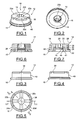
- the device 10 has a generally annular shape, here of round cross section.
- I1 essentially comprises a body 12 provided with an axial passage 14 for the sealed passage of the pipe and a collar 16. Considering the insertion direction of the pipe in the passage 14, the body 12 has a proximal end turned towards the flange 16 and an opposite distal end of flat shape.
- the body 12 is intended to be introduced into a correspondingly shaped orifice formed in the partition, sealingly against the latter by the annular collar 16.
- the body 12 comprises a core 18 of rigid material ensuring the maintenance of the pipe and giving the body sufficient rigidity to allow it to be subjected to mechanical stresses without causing major deformation of the device.
- the core 18 is made of composite material.
- the core 18 comprises a set of holding sectors 20-a, 20-b, 20-c, 20-d, here four in number, angularly distributed within the body 12.
- Each sector extends from a common annular base 22 forming the flange 16, and comprises a branch 24 having a first proximal end extending from the base 22 and a distal end provided with a skid. support 26.
- Each pad 26 has, internally, a bearing surface 28 for the pipe, facing the passage 14 and projecting therein and, externally, an annular shoulder 30 which delimits, with the outer peripheral surface 32 of the branch 24 and with a radial surface 34 of the base 22, a peripheral groove 36.
- the support pads and, in particular, the bearing surfaces 28, are arranged in pairs facing each other so as to form a distal portion of the passage 14.
- the holding sectors will thus be designed so that the passage delimited by the bearing surfaces 28 corresponds substantially to the external diameter of the pipe.
- the diameter of the passage defined by the pad at the base of the pads is slightly greater than that of the while the diameter of this passage at the distal end of the pads is slightly less than that of the pipe.
- the core 18 is made of rigid material, thanks to the cantilevered disposition of the bearing surfaces 28 with respect to the base 22, and in particular thanks to the presence of the branches 24, when introducing the pipe, the holding sectors 20a, 20b, 20c, 20d are able to move radially outwards, by deformation of the branches 24.
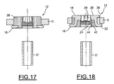
- the support pads are likely to adopt a first configuration of rest, visible on the Figures 1 to 7 , and an active position, adopted after introduction of the pipe in the passage 14, visible on the Figures 19 to 22 .
- inclination of the bearing surfaces 28 will be slightly convergent towards the distal end of the passage 14 at an angle corresponding substantially to the angle of angular deformation of the holding sectors during the introduction of the pipe , so as, after introduction, to obtain bearing surfaces 28 parallel to the axis of the passage 14 which then apply flat against the outer peripheral surface of the pipe.
- the body 12 comprises a sealing material disposed between the holding sectors 20-a, 20-b, 20-c and 20-d, inside and outside the core 18.
- the body 12 comprises radial partitions, such as 38, elastically deformable.
- the body 12 further comprises an outer annular ring 40 of sealing material surrounding the holding sectors 20-a, 20-b, 20-c and 20-d.
- the sealing material is disposed in the groove 36 to form a peripheral mounting zone through which the body is mounted on the partition.
- the body 12 comprises an inner sleeve 42 of sealing material, bordering, internally, the branches 24 of the holding sectors.
- this sleeve 42 is internally provided with a set of coaxial ribs, such as 44, and delimits, together with the bearing surfaces 28, the passage 14 for the pipe.
- the sealing material comprises silicone.
- any other elastically deformable material suitable for the intended use could also be used in place of silicone.
- the partitions 38, the outer strip 40 and the inner sleeve 42 are made of material and formed simultaneously during a single molding operation.
- the core 18, including the holding sectors 20-a, 20-b, 20-c, 20-d and the base 22 can be made in one piece by molding a material rigid plastic, the sealing material being then overmolded on the core 18 to create partitions 38, the outer ring 40 and the inner sleeve 42.
- the groove 36 covered with sealing material is intended to constitute a mounting zone of the device on the partition.
- the bearing pads 26 are intended to maintain the predetermined fixed position of the pipe through the partition, while the inner sleeve 42, with its annular ribs 44, is intended to ensure sealing at the pipe .
- the holding sectors are deformed from the rest position to the active position so that the bearing surfaces 28 lie flat against the outer peripheral surface of the pipe C '.
- the sealing material filling the groove 36 is pressed against the peripheral edge of the orifice of the partition, ensuring, in this area, a perfect seal.
- the annular shoulder 30 of the pads is pressed against the wall of the partition, thereby preventing inadvertent tearing of the device which remains held against the wall by the collar 16 and by the shoulder 30.
- the holding device which has just been described also provides electrical insulation between the pipe and the through-wall.
Landscapes
- Engineering & Computer Science (AREA)
- General Engineering & Computer Science (AREA)
- Mechanical Engineering (AREA)
- Gasket Seals (AREA)
- Supports For Pipes And Cables (AREA)
- Branch Pipes, Bends, And The Like (AREA)
Claims (12)
- Dichte Haltevorrichtung für eine Leitung zur dichten Durchführung der Leitung durch eine Trennwand, einen Körper (12) aufweisend, der mit einem dichten axialen Durchgang (14) für die Leitung und einem Umfangsbereich (40) zur dichten Anbringung der Vorrichtung in einer in der Trennwand ausgebildeten Öffnung (O) ausgestattet ist, wobei der Körper (12) eine Gruppe von starren Sektoren (20-a, 20-b, 20-c, 20-d) und ein Dichtmaterial, das zwischen den Sektoren zum Begrenzen des dichten Durchgangs und um die Sektoren herum in dem Umfangsbereich (40) des Körpers, über den dieser in der Trennwand angebracht wird, angeordnet ist, dadurch gekennzeichnet, dass der Körper (12) durch Umspritzen aus einem Stück gefertigt ist und die Gruppe von starren Sektoren eine Gruppe von starren Haltesektoren (20-a, 20-b, 20-c, 20-d) ist, die jeweils einen Stützschuh (26) aufweisen, der eine Stützfläche (28) aufweist, die geeignet ist, flach an der Außenumfangsfläche der Leitung zur Anlage zu kommen.
- Vorrichtung nach Anspruch 1, dadurch gekennzeichnet, dass die Sektoren (20-a, 20-b, 20-c, 20-d) beim Einführen der Leitung durch den dichten Durchgang radial nach außen verschiebbar sind, so dass sie den Umfangsbereich des Körpers gegen die Trennwand drücken, entgegen einer von dem Dichtmaterial ausgeübten Kraft, welche die Stützschuhe (26) in eine Position der Anlage an der Leitung drückt.
- Vorrichtung nach einem der Ansprüche 1 und 2, dadurch gekennzeichnet, dass der Körper einen Kern aus starrem Material aufweist, der einen Fuß (22) aufweist, von dem aus sich die Sektoren erstrecken.
- Vorrichtung nach Anspruch 3, dadurch gekennzeichnet, dass jeder Sektor an der Stelle des Umfangsbereichs (40) des Körpers, an der dieser in der Trennwand angebracht wird, eine radial äußere Auskehlung (36) aufweist, die mit dem Dichtmaterial gefüllt ist.
- Vorrichtung nach einem der Ansprüche 1 bis 4, dadurch gekennzeichnet, dass das Dichtmaterial eine Gruppe von koaxialen und parallelen Rippen (44) aufweist, die sich in den dichten Durchgang vorstehend erstrecken.
- Vorrichtung nach einem der Ansprüche 1 bis 5, dadurch gekennzeichnet, dass sich die Stützschuhe (26) radial vorstehend in den Durchgang erstrecken.
- Vorrichtung nach einem der Ansprüche 1 bis 6, dadurch gekennzeichnet, dass sie vier Haltesektoren aufweist.
- Vorrichtung nach einem der Ansprüche 1 bis 7, dadurch gekennzeichnet, dass die starren Sektoren aus Verbundwerkstoff hergestellt sind.
- Vorrichtung nach einem der Ansprüche 1 bis 8, dadurch gekennzeichnet, dass das Dichtmaterial Silikon umfasst.
- Vorrichtung nach einem der Ansprüche 1 bis 9, dadurch gekennzeichnet, dass sie ein Mittel zur elektrischen Isolation zwischen der Leitung und der Trennwand bildet.
- Verfahren zur dichten Montage einer Leitung durch eine Trennwand hindurch mittels einer dichten Haltevorrichtung (10) nach einem der Ansprüche 1 bis 10, dadurch gekennzeichnet, dass es die folgenden Schritte aufweist:- Einsetzen der Vorrichtung (10) in eine in der Trennwand (C) ausgebildete Öffnung (O); und- Einführung der Leitung (C') in den dichten Durchgang (14) des Körpers, derart, dass einerseits die Sektoren und das die Sektoren umgebende Dichtmaterial gegen die Trennwand gedrückt werden und andererseits die Stützschuhe gegen die Leitung gedrückt werden.
- Verwendung einer Haltevorrichtung nach einem der Ansprüche 1 bis 10 für die dichte Durchführung durch eine Trennwand eines Tanks eines Luftfahrzeugs.
Applications Claiming Priority (1)
| Application Number | Priority Date | Filing Date | Title |
|---|---|---|---|
| FR0856921A FR2937112B1 (fr) | 2008-10-13 | 2008-10-13 | Dispositif de maintien etanche d'une conduite, procede de montage etanche d'une conduite a travers une cloison et utilisation d'un tel dispositif pour la traversee etanche d'une cloison d'un reservoir d'aeronef |
Publications (2)
| Publication Number | Publication Date |
|---|---|
| EP2175183A1 EP2175183A1 (de) | 2010-04-14 |
| EP2175183B1 true EP2175183B1 (de) | 2015-03-25 |
Family
ID=40627642
Family Applications (1)
| Application Number | Title | Priority Date | Filing Date |
|---|---|---|---|
| EP20090172545 Active EP2175183B1 (de) | 2008-10-13 | 2009-10-08 | Vorrichtung zum Dichthalten einer Leitung, dichtes Montageverfahren einer Leitung durch eine Trennwand, und Verwendung einer solchen Vorrichtung für die dichte Durchführung in einer Trennwand eines Flugzeugtanks |
Country Status (3)
| Country | Link |
|---|---|
| US (1) | US8690161B2 (de) |
| EP (1) | EP2175183B1 (de) |
| FR (1) | FR2937112B1 (de) |
Families Citing this family (11)
| Publication number | Priority date | Publication date | Assignee | Title |
|---|---|---|---|---|
| US9114622B2 (en) * | 2008-05-20 | 2015-08-25 | Hewlett-Packard Development Company, L.P. | Seal and seal/boss assembly |
| WO2013065701A1 (ja) * | 2011-10-31 | 2013-05-10 | 株式会社ハイレックスコーポレーション | シール構造 |
| DE102012007642B4 (de) * | 2012-04-18 | 2014-08-21 | Fass-Frisch Gmbh | Verschlussstopfen für einen Getränkebehälter |
| ES2912034T3 (es) * | 2014-03-31 | 2022-05-24 | Uponor Innovation Ab | Manguito de conexión y caja de colectores |
| JP6220320B2 (ja) * | 2014-07-28 | 2017-10-25 | 株式会社ハイレックスコーポレーション | シール構造 |
| DE102015008987B4 (de) * | 2014-12-12 | 2016-08-11 | Carl Freudenberg Kg | Stoßdämpfer und dessen Verwendung |
| CN116978818A (zh) * | 2016-06-03 | 2023-10-31 | 应用材料公司 | 扩散腔室内部的气流的设计 |
| US10557573B2 (en) * | 2016-11-04 | 2020-02-11 | United Technologies Corporation | Feed through seals and fittings |
| US11732724B2 (en) * | 2019-12-23 | 2023-08-22 | Hunter Fan Company | Ceiling fan blade and grommet |
| EP4209449B1 (de) * | 2022-01-10 | 2024-10-16 | elobau GmbH & Co. KG | Sauglanze |
| US12234911B2 (en) * | 2023-03-20 | 2025-02-25 | Ford Global Technologies, Llc | Seal assembly for vehicle |
Family Cites Families (20)
| Publication number | Priority date | Publication date | Assignee | Title |
|---|---|---|---|---|
| US2234441A (en) * | 1939-05-19 | 1941-03-11 | Gerald C Ludwig | Insulating grommet |
| US2816950A (en) * | 1952-05-15 | 1957-12-17 | Stratoseal Mfg Company | Lead-through terminals |
| BE643087A (de) * | 1963-01-28 | |||
| GB1604444A (en) * | 1977-09-30 | 1981-12-09 | Raychem Ltd | Heatrecoverable articles |
| US4481697A (en) * | 1982-05-28 | 1984-11-13 | General Signal Corporation | Combined strain relief and cord grip |
| GB2217399B (en) * | 1988-04-15 | 1992-02-26 | Austin Rover Group | A seal |
| US5353472A (en) * | 1992-12-28 | 1994-10-11 | Benda Steven J | Grommet/plug |
| FR2703753B1 (fr) * | 1993-04-07 | 1995-07-21 | Sib Adr | Presse-etoupe a montage rapide. |
| US5870799A (en) * | 1994-02-03 | 1999-02-16 | Benda; Steven J. | Grommet |
| JP3010411B2 (ja) * | 1994-03-18 | 2000-02-21 | 矢崎総業株式会社 | 防水ゴム栓および防水コネクタ |
| US5553869A (en) * | 1994-12-12 | 1996-09-10 | Dana Corporation | Bonded valve stem seal with retainer tangs |
| EP0950011B1 (de) * | 1997-11-03 | 2002-04-03 | Kurt Oberhofer | Verschluss mit druckausgleichsventil für einen flüssigkeitsbehälter |
| FR2789527B1 (fr) * | 1999-02-08 | 2001-03-16 | Sylea | Ensemble de traversee de cloisons |
| FR2813370B1 (fr) * | 2000-08-22 | 2002-11-29 | C F Gomma Barre Thomas S A | Joints d'etancheite pour la traversee de parois |
| US7481436B2 (en) * | 2002-09-09 | 2009-01-27 | Dura Global Technologies, Inc. | Two part grommet with hard plastic locking prongs |
| US7455192B2 (en) * | 2004-11-03 | 2008-11-25 | Illinois Tool Works Inc. | Overmolded adhesive hole plug |
| US7261306B2 (en) * | 2005-04-06 | 2007-08-28 | Illinois Tool Works Inc | Grommet device |
| US20100252572A1 (en) * | 2006-01-25 | 2010-10-07 | Stephan Sendelbach | Flexible fuel tank carrier and method of dispensing fuel |
| US7915507B2 (en) * | 2006-11-16 | 2011-03-29 | Stephen Carol Onheiser | Methods and apparatus for mounting cymbals |
| US7681923B2 (en) * | 2006-11-17 | 2010-03-23 | The Boeing Company | Fitting and associated grommet for supporting a conduit penetrating a panel |
-
2008
- 2008-10-13 FR FR0856921A patent/FR2937112B1/fr active Active
-
2009
- 2009-10-08 EP EP20090172545 patent/EP2175183B1/de active Active
- 2009-10-08 US US12/575,993 patent/US8690161B2/en active Active
Also Published As
| Publication number | Publication date |
|---|---|
| US20100109259A1 (en) | 2010-05-06 |
| FR2937112A1 (fr) | 2010-04-16 |
| EP2175183A1 (de) | 2010-04-14 |
| US8690161B2 (en) | 2014-04-08 |
| FR2937112B1 (fr) | 2010-11-12 |
Similar Documents
| Publication | Publication Date | Title |
|---|---|---|
| EP2175183B1 (de) | Vorrichtung zum Dichthalten einer Leitung, dichtes Montageverfahren einer Leitung durch eine Trennwand, und Verwendung einer solchen Vorrichtung für die dichte Durchführung in einer Trennwand eines Flugzeugtanks | |
| EP2878873A1 (de) | Patronenartige Schnellkupplungsvorrichtung | |
| FR2766552A1 (fr) | Dispositif pour l'assemblage de deux elements de canalisation, et assemblages d'elements de canalisation en comportant application | |
| EP0011187B1 (de) | Verriegelte Muffenverbindung | |
| EP1612443B1 (de) | Kupplungsausrücklager und Verfahren zu seiner Herstellung. | |
| EP1289858B1 (de) | Spender mit befestigungsorgan und umlaufender dichtung | |
| EP2893227A2 (de) | Bürstenartige kreisförmige dichtung | |
| EP1489713A1 (de) | Dichte Wanddurchführungsvorrichtung | |
| EP2818780A1 (de) | Abnehmbare Anschlussvorrichtung zwischen zwei Schlauchleitungen | |
| WO2013050693A1 (fr) | Dispositif de distribution de produit fluide | |
| EP1941201B1 (de) | Verbindungsvorrichtung mit geschweisstem körper | |
| FR2568327A1 (fr) | Dispositif de fixation sur une paroi du conduit de gainage d'une commande a cable | |
| FR3092892A1 (fr) | Dispositif de raccordement d’un tube a rupture sonore | |
| EP3749539B1 (de) | Einfüllbaugruppe für kraftstoff oder reinigungsmittel eines kraftfahrzeugs | |
| EP1009682A1 (de) | Vorrichtung und verfahren zur halterung eines dosierorganes in einem behälter der abzugebende produkte enthält | |
| FR2637958A1 (fr) | Raccord, notamment pour circuit hydraulique haute pression | |
| EP1800949B1 (de) | Signalleuchteneinheit für ein Kraftfahrzeug mit einer Stange, welche mit einem Positionierungsteil und einem Teil zur Befestigung an der Karosserie versehen ist. | |
| EP1450963B1 (de) | Pumpe sowie vorrichtung zur abgabe von fluiden medien mit einer solchen pumpe | |
| EP1317365B1 (de) | Bremskraftverstärker mit dichtungsanordnung | |
| FR2575427A1 (fr) | Dispositif pour realiser une fixation etanche d'un organe sur une paroi, notamment une tole de carrosserie automobile et appplication d'un tel dispositif a la fixation d'accessoires automobiles, en particulier a la fixation d'une embase d'antenne | |
| FR3073918B1 (fr) | Dispositif anti-retour de fluide monobloc dans un aeronef et procede de fabrication d'un tel dispositif | |
| EP3985295A1 (de) | Fluidverbindung vom typ patrone | |
| EP0392908A1 (de) | Kupplung für Leitungen | |
| WO2020193898A1 (fr) | Dispositif de traversée étanche d'une gaine de câble au travers d'une ouverture d'un tablier de véhicule automobile | |
| EP3795369A1 (de) | Nabe zur montage in rotation um eine achse in bezug auf ein feststehendes organ |
Legal Events
| Date | Code | Title | Description |
|---|---|---|---|
| PUAI | Public reference made under article 153(3) epc to a published international application that has entered the european phase |
Free format text: ORIGINAL CODE: 0009012 |
|
| AK | Designated contracting states |
Kind code of ref document: A1 Designated state(s): AT BE BG CH CY CZ DE DK EE ES FI FR GB GR HR HU IE IS IT LI LT LU LV MC MK MT NL NO PL PT RO SE SI SK SM TR |
|
| AX | Request for extension of the european patent |
Extension state: AL BA RS |
|
| 17P | Request for examination filed |
Effective date: 20100811 |
|
| 17Q | First examination report despatched |
Effective date: 20100914 |
|
| GRAP | Despatch of communication of intention to grant a patent |
Free format text: ORIGINAL CODE: EPIDOSNIGR1 |
|
| RIC1 | Information provided on ipc code assigned before grant |
Ipc: F16L 5/10 20060101ALI20140929BHEP Ipc: F16L 5/02 20060101AFI20140929BHEP Ipc: B64D 37/00 20060101ALI20140929BHEP Ipc: B60R 16/02 20060101ALI20140929BHEP |
|
| INTG | Intention to grant announced |
Effective date: 20141024 |
|
| GRAS | Grant fee paid |
Free format text: ORIGINAL CODE: EPIDOSNIGR3 |
|
| GRAA | (expected) grant |
Free format text: ORIGINAL CODE: 0009210 |
|
| AK | Designated contracting states |
Kind code of ref document: B1 Designated state(s): AT BE BG CH CY CZ DE DK EE ES FI FR GB GR HR HU IE IS IT LI LT LU LV MC MK MT NL NO PL PT RO SE SI SK SM TR |
|
| REG | Reference to a national code |
Ref country code: GB Ref legal event code: FG4D Free format text: NOT ENGLISH |
|
| REG | Reference to a national code |
Ref country code: CH Ref legal event code: EP |
|
| REG | Reference to a national code |
Ref country code: IE Ref legal event code: FG4D Free format text: LANGUAGE OF EP DOCUMENT: FRENCH |
|
| REG | Reference to a national code |
Ref country code: DE Ref legal event code: R096 Ref document number: 602009030144 Country of ref document: DE Effective date: 20150507 |
|
| REG | Reference to a national code |
Ref country code: AT Ref legal event code: REF Ref document number: 718093 Country of ref document: AT Kind code of ref document: T Effective date: 20150515 |
|
| PG25 | Lapsed in a contracting state [announced via postgrant information from national office to epo] |
Ref country code: LT Free format text: LAPSE BECAUSE OF FAILURE TO SUBMIT A TRANSLATION OF THE DESCRIPTION OR TO PAY THE FEE WITHIN THE PRESCRIBED TIME-LIMIT Effective date: 20150325 Ref country code: SE Free format text: LAPSE BECAUSE OF FAILURE TO SUBMIT A TRANSLATION OF THE DESCRIPTION OR TO PAY THE FEE WITHIN THE PRESCRIBED TIME-LIMIT Effective date: 20150325 Ref country code: FI Free format text: LAPSE BECAUSE OF FAILURE TO SUBMIT A TRANSLATION OF THE DESCRIPTION OR TO PAY THE FEE WITHIN THE PRESCRIBED TIME-LIMIT Effective date: 20150325 Ref country code: HR Free format text: LAPSE BECAUSE OF FAILURE TO SUBMIT A TRANSLATION OF THE DESCRIPTION OR TO PAY THE FEE WITHIN THE PRESCRIBED TIME-LIMIT Effective date: 20150325 |
|
| REG | Reference to a national code |
Ref country code: AT Ref legal event code: MK05 Ref document number: 718093 Country of ref document: AT Kind code of ref document: T Effective date: 20150325 |
|
| REG | Reference to a national code |
Ref country code: LT Ref legal event code: MG4D |
|
| PG25 | Lapsed in a contracting state [announced via postgrant information from national office to epo] |
Ref country code: LV Free format text: LAPSE BECAUSE OF FAILURE TO SUBMIT A TRANSLATION OF THE DESCRIPTION OR TO PAY THE FEE WITHIN THE PRESCRIBED TIME-LIMIT Effective date: 20150325 Ref country code: GR Free format text: LAPSE BECAUSE OF FAILURE TO SUBMIT A TRANSLATION OF THE DESCRIPTION OR TO PAY THE FEE WITHIN THE PRESCRIBED TIME-LIMIT Effective date: 20150626 |
|
| PG25 | Lapsed in a contracting state [announced via postgrant information from national office to epo] |
Ref country code: NL Free format text: LAPSE BECAUSE OF FAILURE TO SUBMIT A TRANSLATION OF THE DESCRIPTION OR TO PAY THE FEE WITHIN THE PRESCRIBED TIME-LIMIT Effective date: 20150325 |
|
| PG25 | Lapsed in a contracting state [announced via postgrant information from national office to epo] |
Ref country code: EE Free format text: LAPSE BECAUSE OF FAILURE TO SUBMIT A TRANSLATION OF THE DESCRIPTION OR TO PAY THE FEE WITHIN THE PRESCRIBED TIME-LIMIT Effective date: 20150325 Ref country code: ES Free format text: LAPSE BECAUSE OF FAILURE TO SUBMIT A TRANSLATION OF THE DESCRIPTION OR TO PAY THE FEE WITHIN THE PRESCRIBED TIME-LIMIT Effective date: 20150325 Ref country code: SK Free format text: LAPSE BECAUSE OF FAILURE TO SUBMIT A TRANSLATION OF THE DESCRIPTION OR TO PAY THE FEE WITHIN THE PRESCRIBED TIME-LIMIT Effective date: 20150325 Ref country code: RO Free format text: LAPSE BECAUSE OF FAILURE TO SUBMIT A TRANSLATION OF THE DESCRIPTION OR TO PAY THE FEE WITHIN THE PRESCRIBED TIME-LIMIT Effective date: 20150325 Ref country code: PT Free format text: LAPSE BECAUSE OF FAILURE TO SUBMIT A TRANSLATION OF THE DESCRIPTION OR TO PAY THE FEE WITHIN THE PRESCRIBED TIME-LIMIT Effective date: 20150727 Ref country code: CZ Free format text: LAPSE BECAUSE OF FAILURE TO SUBMIT A TRANSLATION OF THE DESCRIPTION OR TO PAY THE FEE WITHIN THE PRESCRIBED TIME-LIMIT Effective date: 20150325 |
|
| PG25 | Lapsed in a contracting state [announced via postgrant information from national office to epo] |
Ref country code: PL Free format text: LAPSE BECAUSE OF FAILURE TO SUBMIT A TRANSLATION OF THE DESCRIPTION OR TO PAY THE FEE WITHIN THE PRESCRIBED TIME-LIMIT Effective date: 20150325 Ref country code: AT Free format text: LAPSE BECAUSE OF FAILURE TO SUBMIT A TRANSLATION OF THE DESCRIPTION OR TO PAY THE FEE WITHIN THE PRESCRIBED TIME-LIMIT Effective date: 20150325 Ref country code: IS Free format text: LAPSE BECAUSE OF FAILURE TO SUBMIT A TRANSLATION OF THE DESCRIPTION OR TO PAY THE FEE WITHIN THE PRESCRIBED TIME-LIMIT Effective date: 20150725 |
|
| REG | Reference to a national code |
Ref country code: DE Ref legal event code: R097 Ref document number: 602009030144 Country of ref document: DE |
|
| PG25 | Lapsed in a contracting state [announced via postgrant information from national office to epo] |
Ref country code: DK Free format text: LAPSE BECAUSE OF FAILURE TO SUBMIT A TRANSLATION OF THE DESCRIPTION OR TO PAY THE FEE WITHIN THE PRESCRIBED TIME-LIMIT Effective date: 20150325 |
|
| PLBE | No opposition filed within time limit |
Free format text: ORIGINAL CODE: 0009261 |
|
| STAA | Information on the status of an ep patent application or granted ep patent |
Free format text: STATUS: NO OPPOSITION FILED WITHIN TIME LIMIT |
|
| 26N | No opposition filed |
Effective date: 20160105 |
|
| PG25 | Lapsed in a contracting state [announced via postgrant information from national office to epo] |
Ref country code: IT Free format text: LAPSE BECAUSE OF FAILURE TO SUBMIT A TRANSLATION OF THE DESCRIPTION OR TO PAY THE FEE WITHIN THE PRESCRIBED TIME-LIMIT Effective date: 20150325 |
|
| PG25 | Lapsed in a contracting state [announced via postgrant information from national office to epo] |
Ref country code: SI Free format text: LAPSE BECAUSE OF FAILURE TO SUBMIT A TRANSLATION OF THE DESCRIPTION OR TO PAY THE FEE WITHIN THE PRESCRIBED TIME-LIMIT Effective date: 20150325 Ref country code: LU Free format text: LAPSE BECAUSE OF FAILURE TO SUBMIT A TRANSLATION OF THE DESCRIPTION OR TO PAY THE FEE WITHIN THE PRESCRIBED TIME-LIMIT Effective date: 20151008 |
|
| REG | Reference to a national code |
Ref country code: CH Ref legal event code: PL |
|
| PG25 | Lapsed in a contracting state [announced via postgrant information from national office to epo] |
Ref country code: MC Free format text: LAPSE BECAUSE OF FAILURE TO SUBMIT A TRANSLATION OF THE DESCRIPTION OR TO PAY THE FEE WITHIN THE PRESCRIBED TIME-LIMIT Effective date: 20150325 |
|
| REG | Reference to a national code |
Ref country code: IE Ref legal event code: MM4A |
|
| PG25 | Lapsed in a contracting state [announced via postgrant information from national office to epo] |
Ref country code: LI Free format text: LAPSE BECAUSE OF NON-PAYMENT OF DUE FEES Effective date: 20151031 Ref country code: CH Free format text: LAPSE BECAUSE OF NON-PAYMENT OF DUE FEES Effective date: 20151031 |
|
| REG | Reference to a national code |
Ref country code: FR Ref legal event code: PLFP Year of fee payment: 8 |
|
| PG25 | Lapsed in a contracting state [announced via postgrant information from national office to epo] |
Ref country code: IE Free format text: LAPSE BECAUSE OF NON-PAYMENT OF DUE FEES Effective date: 20151008 |
|
| PG25 | Lapsed in a contracting state [announced via postgrant information from national office to epo] |
Ref country code: SM Free format text: LAPSE BECAUSE OF FAILURE TO SUBMIT A TRANSLATION OF THE DESCRIPTION OR TO PAY THE FEE WITHIN THE PRESCRIBED TIME-LIMIT Effective date: 20150325 Ref country code: HU Free format text: LAPSE BECAUSE OF FAILURE TO SUBMIT A TRANSLATION OF THE DESCRIPTION OR TO PAY THE FEE WITHIN THE PRESCRIBED TIME-LIMIT; INVALID AB INITIO Effective date: 20091008 Ref country code: NO Free format text: LAPSE BECAUSE OF FAILURE TO SUBMIT A TRANSLATION OF THE DESCRIPTION OR TO PAY THE FEE WITHIN THE PRESCRIBED TIME-LIMIT Effective date: 20150625 Ref country code: BG Free format text: LAPSE BECAUSE OF FAILURE TO SUBMIT A TRANSLATION OF THE DESCRIPTION OR TO PAY THE FEE WITHIN THE PRESCRIBED TIME-LIMIT Effective date: 20150325 |
|
| PG25 | Lapsed in a contracting state [announced via postgrant information from national office to epo] |
Ref country code: CY Free format text: LAPSE BECAUSE OF FAILURE TO SUBMIT A TRANSLATION OF THE DESCRIPTION OR TO PAY THE FEE WITHIN THE PRESCRIBED TIME-LIMIT Effective date: 20150325 |
|
| PG25 | Lapsed in a contracting state [announced via postgrant information from national office to epo] |
Ref country code: BE Free format text: LAPSE BECAUSE OF NON-PAYMENT OF DUE FEES Effective date: 20151031 |
|
| REG | Reference to a national code |
Ref country code: FR Ref legal event code: PLFP Year of fee payment: 9 |
|
| PG25 | Lapsed in a contracting state [announced via postgrant information from national office to epo] |
Ref country code: MT Free format text: LAPSE BECAUSE OF FAILURE TO SUBMIT A TRANSLATION OF THE DESCRIPTION OR TO PAY THE FEE WITHIN THE PRESCRIBED TIME-LIMIT Effective date: 20150325 Ref country code: TR Free format text: LAPSE BECAUSE OF FAILURE TO SUBMIT A TRANSLATION OF THE DESCRIPTION OR TO PAY THE FEE WITHIN THE PRESCRIBED TIME-LIMIT Effective date: 20150325 |
|
| PG25 | Lapsed in a contracting state [announced via postgrant information from national office to epo] |
Ref country code: MK Free format text: LAPSE BECAUSE OF FAILURE TO SUBMIT A TRANSLATION OF THE DESCRIPTION OR TO PAY THE FEE WITHIN THE PRESCRIBED TIME-LIMIT Effective date: 20150325 |
|
| REG | Reference to a national code |
Ref country code: FR Ref legal event code: PLFP Year of fee payment: 10 |
|
| PGFP | Annual fee paid to national office [announced via postgrant information from national office to epo] |
Ref country code: DE Payment date: 20241010 Year of fee payment: 16 |
|
| PGFP | Annual fee paid to national office [announced via postgrant information from national office to epo] |
Ref country code: GB Payment date: 20241028 Year of fee payment: 16 |
|
| PGFP | Annual fee paid to national office [announced via postgrant information from national office to epo] |
Ref country code: FR Payment date: 20241024 Year of fee payment: 16 |