EP2174820A2 - Innenwand für einen Fahrzeugtank - Google Patents
Innenwand für einen Fahrzeugtank Download PDFInfo
- Publication number
- EP2174820A2 EP2174820A2 EP09450182A EP09450182A EP2174820A2 EP 2174820 A2 EP2174820 A2 EP 2174820A2 EP 09450182 A EP09450182 A EP 09450182A EP 09450182 A EP09450182 A EP 09450182A EP 2174820 A2 EP2174820 A2 EP 2174820A2
- Authority
- EP
- European Patent Office
- Prior art keywords
- wall
- peripheral part
- tank
- profile
- wall according
- Prior art date
- Legal status (The legal status is an assumption and is not a legal conclusion. Google has not performed a legal analysis and makes no representation as to the accuracy of the status listed.)
- Granted
Links
Images


Classifications
-
- B—PERFORMING OPERATIONS; TRANSPORTING
- B60—VEHICLES IN GENERAL
- B60K—ARRANGEMENT OR MOUNTING OF PROPULSION UNITS OR OF TRANSMISSIONS IN VEHICLES; ARRANGEMENT OR MOUNTING OF PLURAL DIVERSE PRIME-MOVERS IN VEHICLES; AUXILIARY DRIVES FOR VEHICLES; INSTRUMENTATION OR DASHBOARDS FOR VEHICLES; ARRANGEMENTS IN CONNECTION WITH COOLING, AIR INTAKE, GAS EXHAUST OR FUEL SUPPLY OF PROPULSION UNITS IN VEHICLES
- B60K15/00—Arrangement in connection with fuel supply of combustion engines or other fuel consuming energy converters, e.g. fuel cells; Mounting or construction of fuel tanks
- B60K15/03—Fuel tanks
- B60K15/077—Fuel tanks with means modifying or controlling distribution or motion of fuel, e.g. to prevent noise, surge, splash or fuel starvation
-
- B—PERFORMING OPERATIONS; TRANSPORTING
- B60—VEHICLES IN GENERAL
- B60K—ARRANGEMENT OR MOUNTING OF PROPULSION UNITS OR OF TRANSMISSIONS IN VEHICLES; ARRANGEMENT OR MOUNTING OF PLURAL DIVERSE PRIME-MOVERS IN VEHICLES; AUXILIARY DRIVES FOR VEHICLES; INSTRUMENTATION OR DASHBOARDS FOR VEHICLES; ARRANGEMENTS IN CONNECTION WITH COOLING, AIR INTAKE, GAS EXHAUST OR FUEL SUPPLY OF PROPULSION UNITS IN VEHICLES
- B60K15/00—Arrangement in connection with fuel supply of combustion engines or other fuel consuming energy converters, e.g. fuel cells; Mounting or construction of fuel tanks
- B60K15/03—Fuel tanks
- B60K2015/03164—Modular concepts for fuel tanks
-
- B—PERFORMING OPERATIONS; TRANSPORTING
- B60—VEHICLES IN GENERAL
- B60K—ARRANGEMENT OR MOUNTING OF PROPULSION UNITS OR OF TRANSMISSIONS IN VEHICLES; ARRANGEMENT OR MOUNTING OF PLURAL DIVERSE PRIME-MOVERS IN VEHICLES; AUXILIARY DRIVES FOR VEHICLES; INSTRUMENTATION OR DASHBOARDS FOR VEHICLES; ARRANGEMENTS IN CONNECTION WITH COOLING, AIR INTAKE, GAS EXHAUST OR FUEL SUPPLY OF PROPULSION UNITS IN VEHICLES
- B60K15/00—Arrangement in connection with fuel supply of combustion engines or other fuel consuming energy converters, e.g. fuel cells; Mounting or construction of fuel tanks
- B60K15/03—Fuel tanks
- B60K2015/03328—Arrangements or special measures related to fuel tanks or fuel handling
- B60K2015/0344—Arrangements or special measures related to fuel tanks or fuel handling comprising baffles
-
- B—PERFORMING OPERATIONS; TRANSPORTING
- B60—VEHICLES IN GENERAL
- B60Y—INDEXING SCHEME RELATING TO ASPECTS CROSS-CUTTING VEHICLE TECHNOLOGY
- B60Y2200/00—Type of vehicle
- B60Y2200/10—Road Vehicles
- B60Y2200/14—Trucks; Load vehicles, Busses
Definitions
- the present invention relates to an inner wall for a vehicle tank having an infiltratable tank wall, the inner wall having a peripheral part and a central wall part.
- the invention further relates to a vehicle tank which is equipped with at least one such inner wall.
- baffles of this type can be used both as partitions without opening or baffles with openings.
- One from the DE 202 08 039 U1 known baffle of the type mentioned is designed as a filigree casting of steel and its peripheral part is formed by the beaded edge of the wall part.
- To mount the inner wall of the flanged edge is verclincht with the tank wall, ie it is produced by joint deformation of the peripheral part and the tank wall simultaneously beads in both parts, which connect the inner wall with the tank wall.
- This has the disadvantage that the flanged edge of the inner wall must be countered from the inside with a die in order to withstand the pressure of the applied to the tank wall from the outside Sickstkovs can.
- the edge for clinching must be correspondingly thin-walled, which offers little stability.
- the invention has for its object to provide an inner wall for a vehicle tank, which is connected in a simpler way with the tank wall and results in a stable construction.
- peripheral part is preformed on the outside with at least one circumferential or a plurality of circumferentially distributed groove (s) for infiltrating the tank wall therein.
- the peripheral part of the inner wall itself forms the die for the beading of the tank wall, which eliminates the need for countering from the inside during the beading process. This significantly facilitates the production, since it is no longer necessary to intervene in the tank from the inside.
- the Sickgeometrie already predefined in the peripheral part of the inner wall so that lower manufacturing tolerances can be achieved. It is also less suction power necessary because only the tank wall must be deformed.
- the material of the peripheral part itself need not be deformable, so that this can be performed as a correspondingly stable part, for example as a casting, forged or bent extruded part.
- the inner wall according to the invention enables a greatly simplified production of highly stable vehicle tanks.
- the peripheral part in section has approximately T-profile, wherein the wall part adjoins the central web of the T-profile.
- the wall part lies centrally to the peripheral part or the peripheral part protrudes symmetrically on both sides of the inner part, which leads to a much better introduction of force and to a minimization of the bending stresses between peripheral part and wall part compared to the known inner walls with flanged edge.
- the T-profile is stiffened with reinforcing ribs, whereby a further cross-sectional reduction of the T-profile is possible with the same strength.
- the wall thickness of the wall part decreases inwards from. As a result, a weight reduction without impairing the strength can be achieved again.
- the inner wall of the invention can be made of any suitably stable material, such as steel or hard plastic per se.
- a casting, forging or extruded part preferably made of aluminum, which on the one hand offers high stability with low weight and on the other hand, the risk of contact corrosion between the peripheral part and the tank wall hinan discourse.
- the wall part may also preferably be a cast, forged or extruded part, preferably made of aluminum.
- a preferred embodiment is that the wall part is a separate element and embedded with its outer portion in the peripheral part or riveted to the peripheral part, screwed, welded, clinched or glued, for example, if the wall part of a cheaper thermoforming sheet or other material, e.g. Plastic should be made as the peripheral part.
- the wall part may preferably be integral with the peripheral part.
- a further preferred embodiment of the invention which is particularly suitable for parallelepipedic vehicle tanks, is characterized in that it has a rounded-polygonal contour and the grooves are distributed in the polygon corners.
- the beads can be limited to a few peripheral locations, which further simplifies the production of the tank.
- the inner wall of the invention forms a baffle and the wall part - and preferably also the peripheral part - are provided with corresponding openings.
- the invention also provides a vehicle tank with a tank wall of sheet metal, in particular aluminum sheet, which is characterized by at least one inner wall of the type presented here, in whose groove (s) the tank wall is inserted.
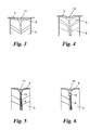
- a segment of a tank wall 1 of a vehicle tank 2 (not shown), for example a fuel tank for a truck, is shown.
- the tank wall 1 is made of a thin-walled metal sheet, for example steel sheet or preferably aluminum sheet.
- an inner wall 3 is used, for example, a partition for a multi-chamber tank or - as shown - as a baffle with openings. 4
- Fig. 2 is the inner wall 3 made as a one-piece casting of metal, for example of steel or die-cast aluminum, or as a forged or bent extrusion.
- the inner wall 3 is composed of an approximately hoop-shaped peripheral part 5 and a central wall part 6 which adjoins approximately centrally on the inside of the peripheral part 5.
- the peripheral part 5 seen in cross-section approximately T-profile, wherein the wall part 6 connects to the central web 7 of the T-profile.
- the web thickness d 1 of the central web 7 increases toward the outside progressively and runs in the legs 8, 9 of the T-profile round.
- the T-profile of the peripheral part 5 may additionally be stiffened with preferably radial reinforcing ribs 10.
- the peripheral part 5 is provided on its outside with (here) four distributed over its circumference grooves 11, which are mitgefertigt in the manufacture of the inner wall 3, for example by molding during casting, milling, etc.
- the inner wall 3 has a rounded-polygonal peripheral contour and the grooves 11 are preferably formed only in the areas of the polygon corners in the peripheral part 5.
- the grooves 11 are used for subsequent seeding of the tank wall 2 by applying a corresponding bead punch (not shown) on the outside of the tank wall 2, as in the 3 and 4 shown in detail.
- Fig. 3 shows the mounting situation of the inner wall 3 in the tank wall 2 before the seeding of the tank wall 2
- Fig. 4 shows the situation at the end of assembly after the seeding of the tank wall 2 in the grooves 11, whereby the tank wall 2 receives beads 12.
- circumferentially distributed grooves 11 and a single circumferential groove 11 could be provided, for example, for vehicle tanks 2 with a cylindrical cross section, for which the inner wall 3 has a corresponding cylindrical peripheral contour.
- the grooves 11 may also have other than the linear course shown, for example, corrugated or zig-zag shaped to form corrugated or zigzag-shaped beads 12 therein.
- the peripheral part 5 can be provided with openings 13, in particular at the lowermost point of the vehicle tank 2, in order to form an overflow possibility between the chambers separated by the baffle.
- FIGS. 5 and 6 show two alternative variants of the inner wall 3, in which the wall part 6 is inserted as a separate part in the peripheral part 5.
- the wall part 6 is cast with its outer region 14 in the peripheral part 5, and in Fig. 5 the wall part 6 is connected to the peripheral part 5 by means of rivets 15.
- the wall part 6 could also be screwed, welded, clinched or glued to the peripheral part 5.
Landscapes
- Engineering & Computer Science (AREA)
- Life Sciences & Earth Sciences (AREA)
- Sustainable Development (AREA)
- Sustainable Energy (AREA)
- Chemical & Material Sciences (AREA)
- Combustion & Propulsion (AREA)
- Transportation (AREA)
- Mechanical Engineering (AREA)
- Body Structure For Vehicles (AREA)
- Cooling, Air Intake And Gas Exhaust, And Fuel Tank Arrangements In Propulsion Units (AREA)
- Blow-Moulding Or Thermoforming Of Plastics Or The Like (AREA)
Abstract
Description
- Die vorliegende Erfindung betrifft eine Innenwand für einen Fahrzeugtank mit einer einsickbaren Tankwandung, wobei die Innenwand einen Umfangsteil und einen zentralen Wandteil hat. Die Erfindung betrifft ferner einen Fahrzeugtank, der mit zumindest einer solchen Innenwand ausgestattet ist.
- Innenwände dieser Art können sowohl als Trennwände ohne Durchbrechung oder Schwallwände mit Durchbrechungen eingesetzt werden. Eine aus der
DE 202 08 039 U1 bekannte Schwallwand der eingangs genannten Art ist als filigraner Gußteil aus Stahl ausgeführt und ihr Umfangsteil wird durch den umgebördelten Rand des Wandteils gebildet. Zur Montage der Innenwand wird der umgebördelte Rand mit der Tankwandung verclincht, d.h. es werden durch gemeinsames Verformen von Umfangsteil und Tankwandung gleichzeitig Sicken in beiden Teilen erzeugt, welche die Innenwand mit der Tankwandung verbinden. Dies hat den Nachteil, daß der umgebördelte Rand der Innenwand von innen mit einer Matrize gegengehalten werden muß, um dem Druck des auf die Tankwandung von außen aufgebrachten Sickstempels widerstehen zu können. Außerdem muß der Rand zum Clinchen entsprechend dünnwandig sein, was wenig Stabilität bietet. - Die Erfindung setzt sich zum Ziel, eine Innenwand für einen Fahrzeugtank zu schaffen, welche auf einfachere Art mit der Tankwandung verbindbar ist und eine stabile Konstruktion ergibt.
- Dieses Ziel wird erfindungsgemäß dadurch erreicht, daß der Umfangsteil außenseitig mit zumindest einer umlaufenden oder mehreren umfangsmäßig verteilten Nut(en) zum darin Einsicken der Tankwandung vorgeformt ist.
- Auf diese Weise bildet der Umfangsteil der Innenwand selbst die Matrize für das Aufsicken der Tankwandung, was ein Gegenhalten von innen beim Sickvorgang erübrigt. Dies erleichtert wesentlich die Fertigung, da nicht mehr von innen in den Tank eingegriffen werden muß. Darüber hinaus ist die Sickgeometrie bereits im Umfangsteil der Innenwand vordefiniert, so daß geringere Fertigungstoleranzen erzielt werden können. Es ist auch weniger Sickkraft nötig, da nur mehr die Tankwandung verformt werden muß. Schließlich braucht das Material des Umfangsteils selbst nicht verformbar zu sein, sodaß dieser als entsprechend stabiler Teil, z.B. als Gußteil, Schmiedeteil oder gebogener Strangpreßteil ausgeführt werden kann. Im Ergebnis ermöglicht die erfindungsgemäße Innenwand eine stark vereinfachte Fertigung hochstabiler Fahrzeugtanks.
- Gemäß einer bevorzugten Ausführungsform der Erfindung hat der Umfangsteil im Schnitt gesehen etwa T-Profil, wobei der Wandteil an den Mittelsteg des T-Profils anschließt. Dadurch liegt der Wandteil mittig zum Umfangsteil bzw. kragt der Umfangsteil symmetrisch zu beiden Seiten des Innenteils aus, was im Vergleich zu den bekannten Innenwänden mit umgebördeltem Rand zu einer wesentlich besseren Krafteinleitung und zu einer Minimierung der Biegebeanspruchungen zwischen Umfangsteil und Wandteil führt.
- Besonders vorteilhaft ist es, wenn die Stegdicke des Mittelstegs des T-Profils nach außen hin zunimmt und in die Schenkel des T-Profils rund ausläuft. Dies ergibt eine optimale Kräfteverteilung mit minimalem Materialeinsatz und entsprechender Gewichtseinsparung.
- Bevorzugt ist das T-Profil mit Verstärkungsrippen ausgesteift, wodurch eine weitere Querschnittsverringerung des T-Profils bei gleichbleibender Festigkeit möglich ist.
- Gemäß einer weiteren bevorzugten Ausführungsform der Erfindung nimmt auch die Wanddicke des Wandteils nach innen hin ab. Dadurch kann nochmals eine Gewichtsreduktion ohne Beeinträchtigung der Festigkeit erzielt werden.
- Die Innenwand der Erfindung kann an sich aus jedem beliebigen entsprechend stabilen Material gefertigt werden, z.B. aus Stahl oder Hartkunststoff. Insbesondere für Fahrzeugtanks mit einer Tankwandung aus Aluminiumblech wird bevorzugt vorgesehen, daß zumindest der Umfangsteil der Innenwand ein Guß-, Schmiede- oder Strangpreßteil ist, bevorzugt aus Aluminium, was einerseits hohe Stabilität bei geringem Gewicht bietet und anderseits die Gefahr einer Kontaktkorrosion zwischen dem Umfangsteil und der Tankwandung hintanhält.
- Auch der Wandteil kann bevorzugt ein Guß-, Schmiede- oder Strangpreßteil sein, bevorzugt aus Aluminium. Eine bevorzugte Ausführungsform besteht darin, daß der Wandteil ein gesondertes Element und mit seinem Außenbereich in den Umfangsteil eingebettet oder mit dem Umfangsteil vernietet, verschraubt, verschweißt, verclincht oder verklebt ist, beispielsweise wenn der Wandteil aus einem kostengünstigeren Tiefziehblech oder anderem Material, z.B. Kunststoff als der Umfangsteil gefertigt werden soll. Alternativ kann der Wandteil bevorzugt mit dem Umfangsteil einstückig sein.
- Eine weitere bevorzugte Ausführungsform der Erfindung, welche sich besonders für parallelepipedische Fahrzeugtanks eignet, zeichnet sich dadurch aus, daß sie eine abgerundet-polygonförmige Kontur hat und die Nuten in den Polygonecken verteilt sind. Dadurch können die Sicken auf einige wenige Umfangsstellen beschränkt werden, was die Fertigung des Tanks weiter vereinfacht.
- Bevorzugt bildet die Innenwand der Erfindung eine Schwallwand und der Wandteil - und bevorzugt auch der Umfangsteil - sind dazu mit entsprechenden Durchbrechungen versehen.
- In einem weiteren Aspekt schafft die Erfindung auch einen Fahrzeugtank mit einer Tankwandung aus Metallblech, insbesondere Aluminiumblech, der sich durch zumindest eine Innenwand der hier vorgestellten Art auszeichnet, in deren Nut(en) die Tankwandung eingesickt ist.
- Die Erfindung wird nachstehend anhand von in den beigeschlossenen Zeichnungen dargestellten Ausführungsbeispielen näher erläutert. In den Zeichnungen zeigen:
-
Fig. 1 einen Ausschnitt aus einem Fahrzeugtank, in den eine Innenwand gemäß der Erfindung eingesetzt ist, in einer Perspektivansicht; -
Fig. 2 einen Halbschnitt der Innenwand vonFig. 1 ; - In
Fig. 1 ist ein Segment einer Tankwandung 1 eines (nicht weiter dargestellten) Fahrzeugtanks 2 gezeigt, beispielsweise eines Kraftstofftanks für einen Lastkraftwagen. Die Tankwandung 1 ist aus einem dünnwandigen Metallblech gefertigt, z.B. Stahlblech oder bevorzugt Aluminiumblech. In den Tank 2 ist eine Innenwand 3 eingesetzt, beispielsweise eine Trennwand für einen Mehrkammertank oder - wie gezeigt - als Schwallwand mit Durchbrechungen 4. - Gemäß
Fig. 2 ist die Innenwand 3 als ein einstückiger Gußteil aus Metall gefertigt, z.B. aus Stahl oder Aluminiumdruckguß, oder als Schmiede- oder gebogener Strangpreßteil. Die Innenwand 3 setzt sich aus einem etwa reifenförmigen Umfangsteil 5 und einem zentralen Wandteil 6 zusammen, der etwa mittig an der Innenseite des Umfangsteils 5 ansetzt. Mit anderen Worten hat der Umfangsteil 5 im Querschnitt gesehen etwa T-Profil, wobei der Wandteil 6 an den Mittelsteg 7 des T-Profils anschließt. - Die Stegdicke d1 des Mittelstegs 7 nimmt nach außen hin fortschreitend zu und läuft in die Schenkel 8, 9 des T-Profils rund aus. Das T-Profil des Umfangsteils 5 kann zusätzlich mit bevorzugt radialen Verstärkungsrippen 10 ausgesteift sein.
- Auch die Wanddicke des Wandteils 6 nimmt vom Mittelsteg 7 ausgehend fortschreitend nach innen hin ab, bis zu der eingezeichneten Wanddicke d2. Beispielsweise beträgt d1 = 2,5 mm und d2 = 2 mm.
- Der Umfangsteil 5 ist an seiner Außenseite mit (hier) vier über seinen Umfang verteilten Nuten 11 versehen, welche bei der Fertigung der Innenwand 3 mitgefertigt werden, z.B. durch Einformung beim Guß, Einfräsen usw. In dem gezeigten Beispiel eines etwa parallelepipedischen Fahrzeugtanks 2 hat die Innenwand 3 eine abgerundet-polygonförmige Umfangskontur und die Nuten 11 sind bevorzugt nur in den Bereichen der Polygonecken in dem Umfangsteil 5 ausgebildet.
- Die Nuten 11 dienen zum anschließenden Einsicken der Tankwandung 2 durch Aufbringen eines entsprechenden Sickstempels (nicht gezeigt) auf die Außenseite der Tankwandung 2, wie in den
Fig. 3 und 4 im Detail dargestellt. -
Fig. 3 zeigt die Montagesituation der Innenwand 3 in der Tankwandung 2 vor dem Einsicken der Tankwandung 2 undFig. 4 zeigt die Situation am Ende der Montage nach dem Einsicken der Tankwandung 2 in die Nuten 11, wodurch die Tankwandung 2 Sicken 12 erhält. - Anstelle von mehreren umfangsmäßig verteilten Nuten 11 könnte auch eine einzige umlaufende Nut 11 vorgesehen werden, beispielsweise für Fahrzeugtanks 2 mit zylindrischem Querschnitt, für welche die Innenwand 3 eine entsprechende zylindrische Umfangskontur hat. Darüber hinaus ist es auch möglich, mehr als eine Nut 11 in Axialrichtung des Tanks 2 gesehen nebeneinanderliegend anzuordnen, d.h. sowohl umfangsmäßig verteilte als auch umlaufende Nuten 11 in einander paralleler Anordnung.
- Falls gewünscht, können die Nuten 11 auch einen anderen als den gezeigten linearen Verlauf haben, beispielsweise gewellt oder zick-zack-förmig, um entsprechend gewellte oder zick-zack-förmige Sicken 12 darin auszuformen.
- Wenn die Innenwand 3 eine Schwallwand bildet, kann optional auch der Umfangsteil 5 mit Durchbrechungen 13 versehen werden, insbesondere an der untersten Stelle des Fahrzeugtanks 2, um dort eine Überlaufmöglichkeit zwischen den durch die Schwallwand abgetrennten Kammern zu bilden.
- Die
Fig. 5 und 6 zeigen zwei alternative Varianten der Innenwand 3, bei welchen der Wandteil 6 als gesonderter Teil in den Umfangsteil 5 eingesetzt ist. InFig. 5 ist der Wandteil 6 mit seinem Außenbereich 14 in den Umfangsteil 5 eingegossen, und inFig. 5 ist der Wandteil 6 mit dem Umfangsteil 5 mittels Nieten 15 verbunden. Alternativ könnte der Wandteil 6 mit dem Umfangsteil 5 auch verschraubt, verschweißt, verclincht oder verklebt werden. - Die Erfindung ist nicht auf die dargestellten Ausführungsformen beschränkt, sondern umfaßt alle Varianten und Modifikationen, die in den Rahmen der anschließenden Ansprüche fallen.
die
Claims (12)
- Innenwand (3) für einen Fahrzeugtank (2) mit einer einsickbaren Tankwandung (1), wobei die Innenwand (3) einen Umfangsteil (5) aus Gußmaterial und einen zentralen Wandteil (6) hat, dadurch gekennzeichnet, daß der Umfangsteil (5) außenseitig mit zumindest einer umlaufenden oder mehreren umfangsmäßig verteilten Nut(en) (11) zum darin Einsicken der Tankwandung (1) vorgeformt ist.
- Innenwand nach Anspruch 1, dadurch gekennzeichnet, daß der Umfangsteil (5) im Schnitt gesehen etwa T-Profil hat, wobei der Wandteil (6) an den Mittelsteg (7) des T-Profils anschließt.
- Innenwand nach Anspruch 2, dadurch gekennzeichnet, daß die Stegdicke des Mittelstegs (7) des T-Profils nach außen hin zunimmt und in die Schenkel (8, 9) des T-Profils rund ausläuft.
- Innenwand nach Anspruch 2 oder 3, dadurch gekennzeichnet, daß das T-Profil mit Verstärkungsrippen (10) ausgesteift ist.
- Innenwand nach einem der Ansprüche 1 bis 4, dadurch gekennzeichnet, daß die Wanddicke des Wandteils (6) nach innen hin abnimmt.
- Innenwand nach einem der Ansprüche 1 bis 5, dadurch gekennzeichnet, daß zumindest ihr Umfangsteil (5) ein Guß-, Schmiede- oder Strangpreßteil ist, bevorzugt aus Aluminium.
- Innenwand nach einem der Ansprüche 1 bis 6, dadurch gekennzeichnet, daß der Wandteil (6) mit seinem Außenbereich (14) in den Umfangsteil (5) eingebettet ist.
- Innenwand nach einem der Ansprüche 1 bis 6, dadurch gekennzeichnet, daß der Wandteil (6) mit dem Umfangsteil (5) vernietet, verschraubt, verschweißt, verclincht oder verklebt ist.
- Innenwand nach einem der Ansprüche 1 bis 6, dadurch gekennzeichnet, daß der Wandteil (6) mit dem Umfangsteil (5) einstückig ist.
- Innenwand nach einem der Ansprüche 1 bis 9, dadurch gekennzeichnet, daß sie eine abgerundet-polygonförmige Kontur hat und die Nuten (11) in den Polygonecken verteilt sind.
- Innenwand nach einem der Ansprüche 1 bis 10, dadurch gekennzeichnet, daß sie eine Schwallwand bildet und der Wandteil (6) und bevorzugt auch der Umfangsteil (5) mit Durchbrechungen (4, 13) versehen sind.
- Fahrzeugtank mit einer Tankwandung aus Metallblech, insbesondere Aluminiumblech, gekennzeichnet durch zumindest eine Innenwand (3) nach einem der Ansprüche 1 bis 11, in deren Nut(en) (11) die Tankwandung (2) eingesickt ist.
Applications Claiming Priority (1)
| Application Number | Priority Date | Filing Date | Title |
|---|---|---|---|
| AT0057908U AT10846U1 (de) | 2008-10-10 | 2008-10-10 | Innenwand für einen fahrzeugtank |
Publications (3)
| Publication Number | Publication Date |
|---|---|
| EP2174820A2 true EP2174820A2 (de) | 2010-04-14 |
| EP2174820A3 EP2174820A3 (de) | 2011-06-22 |
| EP2174820B1 EP2174820B1 (de) | 2012-05-23 |
Family
ID=41057819
Family Applications (1)
| Application Number | Title | Priority Date | Filing Date |
|---|---|---|---|
| EP09450182A Not-in-force EP2174820B1 (de) | 2008-10-10 | 2009-09-24 | Innenwand für einen Fahrzeugtank |
Country Status (2)
| Country | Link |
|---|---|
| EP (1) | EP2174820B1 (de) |
| AT (1) | AT10846U1 (de) |
Cited By (2)
| Publication number | Priority date | Publication date | Assignee | Title |
|---|---|---|---|---|
| US20130240539A1 (en) * | 2010-06-14 | 2013-09-19 | Ford Global Technologies, Llc | Compliance structure for a distensible fuel tank |
| SE1751231A1 (en) * | 2017-10-05 | 2019-04-06 | Scania Cv Ab | Vehicle fuel tank comprising a baffle |
Families Citing this family (2)
| Publication number | Priority date | Publication date | Assignee | Title |
|---|---|---|---|---|
| DE102011113192B4 (de) * | 2011-09-10 | 2017-07-20 | Magna Steyr Fuel Systems Gesmbh | Kraftstoffbehälter |
| DE102017011098A1 (de) * | 2017-11-30 | 2019-06-06 | Scania Cv Ab | Prallblech-Kraftstofftank und Fahrzeug |
Citations (2)
| Publication number | Priority date | Publication date | Assignee | Title |
|---|---|---|---|---|
| DE20205971U1 (de) | 2002-04-17 | 2002-06-27 | Erhard & Soehne Gmbh | Kraftstoffbehälter mit einer Schwallwand |
| DE20208039U1 (de) | 2002-05-21 | 2002-08-22 | Erhard & Soehne Gmbh | Kraftstoffbehälter |
Family Cites Families (6)
| Publication number | Priority date | Publication date | Assignee | Title |
|---|---|---|---|---|
| BE446621A (de) * | ||||
| ATE182530T1 (de) * | 1996-04-01 | 1999-08-15 | Salzburger Aluminium Ag | Kraftstoffbehälter für schallwand für fahrzeuge |
| FR2764671B1 (fr) * | 1997-06-13 | 1999-07-23 | Djp Organisation | Conteneur en materiau composite, notamment pour reservoir de gaz liquefie sous pression, et son procede de fabrication |
| DE19740471C1 (de) * | 1997-09-15 | 1999-02-25 | Man Nutzfahrzeuge Ag | Modularer Fahrzeugbehälter |
| JPH11105557A (ja) * | 1997-10-07 | 1999-04-20 | Unipres Corp | 自動車用燃料タンク |
| KR100461442B1 (ko) * | 2000-12-04 | 2004-12-14 | 현대자동차주식회사 | 연료탱크의 배플 플레이트 |
-
2008
- 2008-10-10 AT AT0057908U patent/AT10846U1/de not_active IP Right Cessation
-
2009
- 2009-09-24 EP EP09450182A patent/EP2174820B1/de not_active Not-in-force
Patent Citations (2)
| Publication number | Priority date | Publication date | Assignee | Title |
|---|---|---|---|---|
| DE20205971U1 (de) | 2002-04-17 | 2002-06-27 | Erhard & Soehne Gmbh | Kraftstoffbehälter mit einer Schwallwand |
| DE20208039U1 (de) | 2002-05-21 | 2002-08-22 | Erhard & Soehne Gmbh | Kraftstoffbehälter |
Cited By (4)
| Publication number | Priority date | Publication date | Assignee | Title |
|---|---|---|---|---|
| US20130240539A1 (en) * | 2010-06-14 | 2013-09-19 | Ford Global Technologies, Llc | Compliance structure for a distensible fuel tank |
| US9321347B2 (en) * | 2010-06-14 | 2016-04-26 | Ford Global Technologies, Llc | Compliance structure for a distensible fuel tank |
| SE1751231A1 (en) * | 2017-10-05 | 2019-04-06 | Scania Cv Ab | Vehicle fuel tank comprising a baffle |
| SE541338C2 (en) * | 2017-10-05 | 2019-07-16 | Scania Cv Ab | Vehicle fuel tank comprising a baffle |
Also Published As
| Publication number | Publication date |
|---|---|
| AT10846U1 (de) | 2009-11-15 |
| EP2174820B1 (de) | 2012-05-23 |
| EP2174820A3 (de) | 2011-06-22 |
Similar Documents
| Publication | Publication Date | Title |
|---|---|---|
| EP2671741B2 (de) | Querlenker sowie Verfahren zum Herstellen des Querlenkers | |
| EP2477765B1 (de) | Verfahren zum herstellen eines lenkers für ein fahrzeug | |
| DE102010036450A1 (de) | B-Säulenverstärkung eines Kraftfahrzeugs | |
| DE102015118099A1 (de) | Verfahren zur Herstellung eines Kraftfahrzeugbauteils | |
| DE102015114105B4 (de) | Aufprallträger für ein Kraftfahrzeug sowie Verfahren zu seiner Herstellung | |
| EP3192680A1 (de) | Federlenker aus stahl | |
| EP0965005A2 (de) | Deformationselement, verfahren zu seiner herstellung und seine verwendung | |
| DE102005011834B4 (de) | Seitlicher Dachrahmen für ein Kraftfahrzeug | |
| EP2174820B1 (de) | Innenwand für einen Fahrzeugtank | |
| DE102008018656B9 (de) | Verfahren zur Herstellung von hochmaßhaltigen Halbschalen | |
| DE102005062330B4 (de) | Hilfsrahmen für Kraftfahrzeuge | |
| EP2483135B1 (de) | Verstärkungsanordnung für eine türsäule eines personenkraftwagens und verfahren zum herstellen einer solchen verstärkungsanordnung | |
| DE102015117025A1 (de) | Versteifungen für Leichtmetallguss-Türquerträger | |
| DE102005057707B4 (de) | A-Säule für ein Kraftfahrzeug | |
| EP2174819B1 (de) | Verbindungselement für Fahrzeugtanksegmente | |
| DE102015100261B4 (de) | Träger für ein Kraftfahrzeug und Herstellungsverfahren für einen Träger für ein Kraftfahrzeug | |
| DE10335666A1 (de) | Zug-Druckstrebe für eine Fahrzeugkarosserie | |
| DE10257259B4 (de) | Vorderrahmen für ein Kraftfahrzeug sowie damit hergestellte Aluminiumkarosserie | |
| DE202011000607U1 (de) | Lenker für eine Fahrzeugradaufhängung | |
| DE102010012722A1 (de) | Versteifungsstrebe für ein Kraftfahrzeug | |
| DE102013107179A1 (de) | Stoßabsorptionsvorrichtung für ein Kraftfahrzeug | |
| DE10134439C2 (de) | Schwenkbares Gestänge für ein öffnungsfähiges Fahrzeugdach sowie Verfahren zum Herstellen desselben | |
| EP3463949A1 (de) | Aussenhautmodul einer fahrzeugtür sowie fahrzeugtür mit einem solchen aussenhautmodul | |
| DE102010012715A1 (de) | Strukturbauteil für eine Fahrzeugkarosserie | |
| DE102009047956A1 (de) | Säule für einen Kraftwagen |
Legal Events
| Date | Code | Title | Description |
|---|---|---|---|
| PUAI | Public reference made under article 153(3) epc to a published international application that has entered the european phase |
Free format text: ORIGINAL CODE: 0009012 |
|
| AK | Designated contracting states |
Kind code of ref document: A2 Designated state(s): AT BE BG CH CY CZ DE DK EE ES FI FR GB GR HR HU IE IS IT LI LT LU LV MC MK MT NL NO PL PT RO SE SI SK SM TR |
|
| AX | Request for extension of the european patent |
Extension state: AL BA RS |
|
| PUAL | Search report despatched |
Free format text: ORIGINAL CODE: 0009013 |
|
| AK | Designated contracting states |
Kind code of ref document: A3 Designated state(s): AT BE BG CH CY CZ DE DK EE ES FI FR GB GR HR HU IE IS IT LI LT LU LV MC MK MT NL NO PL PT RO SE SI SK SM TR |
|
| AX | Request for extension of the european patent |
Extension state: AL BA RS |
|
| 17P | Request for examination filed |
Effective date: 20110625 |
|
| GRAP | Despatch of communication of intention to grant a patent |
Free format text: ORIGINAL CODE: EPIDOSNIGR1 |
|
| RIC1 | Information provided on ipc code assigned before grant |
Ipc: B60K 15/03 20060101AFI20111125BHEP Ipc: B60K 15/077 20060101ALI20111125BHEP |
|
| GRAS | Grant fee paid |
Free format text: ORIGINAL CODE: EPIDOSNIGR3 |
|
| GRAA | (expected) grant |
Free format text: ORIGINAL CODE: 0009210 |
|
| AK | Designated contracting states |
Kind code of ref document: B1 Designated state(s): AT BE BG CH CY CZ DE DK EE ES FI FR GB GR HR HU IE IS IT LI LT LU LV MC MK MT NL NO PL PT RO SE SI SK SM TR |
|
| REG | Reference to a national code |
Ref country code: GB Ref legal event code: FG4D Free format text: NOT ENGLISH |
|
| REG | Reference to a national code |
Ref country code: CH Ref legal event code: EP |
|
| REG | Reference to a national code |
Ref country code: AT Ref legal event code: REF Ref document number: 558913 Country of ref document: AT Kind code of ref document: T Effective date: 20120615 |
|
| REG | Reference to a national code |
Ref country code: IE Ref legal event code: FG4D Free format text: LANGUAGE OF EP DOCUMENT: GERMAN |
|
| REG | Reference to a national code |
Ref country code: SE Ref legal event code: TRGR |
|
| REG | Reference to a national code |
Ref country code: DE Ref legal event code: R096 Ref document number: 502009003604 Country of ref document: DE Effective date: 20120719 |
|
| REG | Reference to a national code |
Ref country code: NL Ref legal event code: T3 |
|
| REG | Reference to a national code |
Ref country code: ES Ref legal event code: FG2A Ref document number: 2388384 Country of ref document: ES Kind code of ref document: T3 Effective date: 20121015 |
|
| REG | Reference to a national code |
Ref country code: LT Ref legal event code: MG4D Effective date: 20120523 |
|
| PG25 | Lapsed in a contracting state [announced via postgrant information from national office to epo] |
Ref country code: LT Free format text: LAPSE BECAUSE OF FAILURE TO SUBMIT A TRANSLATION OF THE DESCRIPTION OR TO PAY THE FEE WITHIN THE PRESCRIBED TIME-LIMIT Effective date: 20120523 Ref country code: CY Free format text: LAPSE BECAUSE OF FAILURE TO SUBMIT A TRANSLATION OF THE DESCRIPTION OR TO PAY THE FEE WITHIN THE PRESCRIBED TIME-LIMIT Effective date: 20120523 Ref country code: FI Free format text: LAPSE BECAUSE OF FAILURE TO SUBMIT A TRANSLATION OF THE DESCRIPTION OR TO PAY THE FEE WITHIN THE PRESCRIBED TIME-LIMIT Effective date: 20120523 Ref country code: IS Free format text: LAPSE BECAUSE OF FAILURE TO SUBMIT A TRANSLATION OF THE DESCRIPTION OR TO PAY THE FEE WITHIN THE PRESCRIBED TIME-LIMIT Effective date: 20120923 Ref country code: NO Free format text: LAPSE BECAUSE OF FAILURE TO SUBMIT A TRANSLATION OF THE DESCRIPTION OR TO PAY THE FEE WITHIN THE PRESCRIBED TIME-LIMIT Effective date: 20120823 |
|
| PGFP | Annual fee paid to national office [announced via postgrant information from national office to epo] |
Ref country code: SE Payment date: 20120920 Year of fee payment: 4 |
|
| PG25 | Lapsed in a contracting state [announced via postgrant information from national office to epo] |
Ref country code: GR Free format text: LAPSE BECAUSE OF FAILURE TO SUBMIT A TRANSLATION OF THE DESCRIPTION OR TO PAY THE FEE WITHIN THE PRESCRIBED TIME-LIMIT Effective date: 20120824 Ref country code: SI Free format text: LAPSE BECAUSE OF FAILURE TO SUBMIT A TRANSLATION OF THE DESCRIPTION OR TO PAY THE FEE WITHIN THE PRESCRIBED TIME-LIMIT Effective date: 20120523 Ref country code: LV Free format text: LAPSE BECAUSE OF FAILURE TO SUBMIT A TRANSLATION OF THE DESCRIPTION OR TO PAY THE FEE WITHIN THE PRESCRIBED TIME-LIMIT Effective date: 20120523 Ref country code: HR Free format text: LAPSE BECAUSE OF FAILURE TO SUBMIT A TRANSLATION OF THE DESCRIPTION OR TO PAY THE FEE WITHIN THE PRESCRIBED TIME-LIMIT Effective date: 20120523 Ref country code: PT Free format text: LAPSE BECAUSE OF FAILURE TO SUBMIT A TRANSLATION OF THE DESCRIPTION OR TO PAY THE FEE WITHIN THE PRESCRIBED TIME-LIMIT Effective date: 20120924 |
|
| PGFP | Annual fee paid to national office [announced via postgrant information from national office to epo] |
Ref country code: ES Payment date: 20120924 Year of fee payment: 4 |
|
| PG25 | Lapsed in a contracting state [announced via postgrant information from national office to epo] |
Ref country code: CZ Free format text: LAPSE BECAUSE OF FAILURE TO SUBMIT A TRANSLATION OF THE DESCRIPTION OR TO PAY THE FEE WITHIN THE PRESCRIBED TIME-LIMIT Effective date: 20120523 Ref country code: RO Free format text: LAPSE BECAUSE OF FAILURE TO SUBMIT A TRANSLATION OF THE DESCRIPTION OR TO PAY THE FEE WITHIN THE PRESCRIBED TIME-LIMIT Effective date: 20120523 Ref country code: SK Free format text: LAPSE BECAUSE OF FAILURE TO SUBMIT A TRANSLATION OF THE DESCRIPTION OR TO PAY THE FEE WITHIN THE PRESCRIBED TIME-LIMIT Effective date: 20120523 Ref country code: EE Free format text: LAPSE BECAUSE OF FAILURE TO SUBMIT A TRANSLATION OF THE DESCRIPTION OR TO PAY THE FEE WITHIN THE PRESCRIBED TIME-LIMIT Effective date: 20120523 Ref country code: DK Free format text: LAPSE BECAUSE OF FAILURE TO SUBMIT A TRANSLATION OF THE DESCRIPTION OR TO PAY THE FEE WITHIN THE PRESCRIBED TIME-LIMIT Effective date: 20120523 |
|
| PGFP | Annual fee paid to national office [announced via postgrant information from national office to epo] |
Ref country code: NL Payment date: 20120920 Year of fee payment: 4 Ref country code: FR Payment date: 20121008 Year of fee payment: 4 |
|
| PG25 | Lapsed in a contracting state [announced via postgrant information from national office to epo] |
Ref country code: PL Free format text: LAPSE BECAUSE OF FAILURE TO SUBMIT A TRANSLATION OF THE DESCRIPTION OR TO PAY THE FEE WITHIN THE PRESCRIBED TIME-LIMIT Effective date: 20120523 |
|
| PGFP | Annual fee paid to national office [announced via postgrant information from national office to epo] |
Ref country code: IT Payment date: 20120930 Year of fee payment: 4 |
|
| PLBE | No opposition filed within time limit |
Free format text: ORIGINAL CODE: 0009261 |
|
| STAA | Information on the status of an ep patent application or granted ep patent |
Free format text: STATUS: NO OPPOSITION FILED WITHIN TIME LIMIT |
|
| BERE | Be: lapsed |
Owner name: ALUTECH -G. M.B.H. Effective date: 20120930 |
|
| PG25 | Lapsed in a contracting state [announced via postgrant information from national office to epo] |
Ref country code: MC Free format text: LAPSE BECAUSE OF NON-PAYMENT OF DUE FEES Effective date: 20120930 |
|
| 26N | No opposition filed |
Effective date: 20130226 |
|
| REG | Reference to a national code |
Ref country code: IE Ref legal event code: MM4A |
|
| REG | Reference to a national code |
Ref country code: DE Ref legal event code: R097 Ref document number: 502009003604 Country of ref document: DE Effective date: 20130226 |
|
| PG25 | Lapsed in a contracting state [announced via postgrant information from national office to epo] |
Ref country code: BE Free format text: LAPSE BECAUSE OF NON-PAYMENT OF DUE FEES Effective date: 20120930 Ref country code: IE Free format text: LAPSE BECAUSE OF NON-PAYMENT OF DUE FEES Effective date: 20120924 Ref country code: BG Free format text: LAPSE BECAUSE OF FAILURE TO SUBMIT A TRANSLATION OF THE DESCRIPTION OR TO PAY THE FEE WITHIN THE PRESCRIBED TIME-LIMIT Effective date: 20120823 |
|
| PG25 | Lapsed in a contracting state [announced via postgrant information from national office to epo] |
Ref country code: MT Free format text: LAPSE BECAUSE OF FAILURE TO SUBMIT A TRANSLATION OF THE DESCRIPTION OR TO PAY THE FEE WITHIN THE PRESCRIBED TIME-LIMIT Effective date: 20120523 |
|
| REG | Reference to a national code |
Ref country code: NL Ref legal event code: V1 Effective date: 20140401 |
|
| REG | Reference to a national code |
Ref country code: SE Ref legal event code: EUG |
|
| PG25 | Lapsed in a contracting state [announced via postgrant information from national office to epo] |
Ref country code: SE Free format text: LAPSE BECAUSE OF NON-PAYMENT OF DUE FEES Effective date: 20130925 |
|
| REG | Reference to a national code |
Ref country code: CH Ref legal event code: PL |
|
| GBPC | Gb: european patent ceased through non-payment of renewal fee |
Effective date: 20130924 |
|
| PG25 | Lapsed in a contracting state [announced via postgrant information from national office to epo] |
Ref country code: SM Free format text: LAPSE BECAUSE OF FAILURE TO SUBMIT A TRANSLATION OF THE DESCRIPTION OR TO PAY THE FEE WITHIN THE PRESCRIBED TIME-LIMIT Effective date: 20120523 Ref country code: LU Free format text: LAPSE BECAUSE OF NON-PAYMENT OF DUE FEES Effective date: 20120924 |
|
| PGFP | Annual fee paid to national office [announced via postgrant information from national office to epo] |
Ref country code: TR Payment date: 20120919 Year of fee payment: 4 |
|
| REG | Reference to a national code |
Ref country code: FR Ref legal event code: ST Effective date: 20140530 |
|
| PG25 | Lapsed in a contracting state [announced via postgrant information from national office to epo] |
Ref country code: LI Free format text: LAPSE BECAUSE OF NON-PAYMENT OF DUE FEES Effective date: 20130930 Ref country code: HU Free format text: LAPSE BECAUSE OF FAILURE TO SUBMIT A TRANSLATION OF THE DESCRIPTION OR TO PAY THE FEE WITHIN THE PRESCRIBED TIME-LIMIT Effective date: 20090924 Ref country code: GB Free format text: LAPSE BECAUSE OF NON-PAYMENT OF DUE FEES Effective date: 20130924 Ref country code: CH Free format text: LAPSE BECAUSE OF NON-PAYMENT OF DUE FEES Effective date: 20130930 |
|
| PG25 | Lapsed in a contracting state [announced via postgrant information from national office to epo] |
Ref country code: IT Free format text: LAPSE BECAUSE OF NON-PAYMENT OF DUE FEES Effective date: 20130924 Ref country code: FR Free format text: LAPSE BECAUSE OF NON-PAYMENT OF DUE FEES Effective date: 20130930 Ref country code: NL Free format text: LAPSE BECAUSE OF NON-PAYMENT OF DUE FEES Effective date: 20140401 |
|
| PGFP | Annual fee paid to national office [announced via postgrant information from national office to epo] |
Ref country code: DE Payment date: 20140922 Year of fee payment: 6 |
|
| REG | Reference to a national code |
Ref country code: ES Ref legal event code: FD2A Effective date: 20150327 |
|
| PG25 | Lapsed in a contracting state [announced via postgrant information from national office to epo] |
Ref country code: ES Free format text: LAPSE BECAUSE OF NON-PAYMENT OF DUE FEES Effective date: 20130925 |
|
| PG25 | Lapsed in a contracting state [announced via postgrant information from national office to epo] |
Ref country code: MK Free format text: LAPSE BECAUSE OF FAILURE TO SUBMIT A TRANSLATION OF THE DESCRIPTION OR TO PAY THE FEE WITHIN THE PRESCRIBED TIME-LIMIT Effective date: 20120523 |
|
| PG25 | Lapsed in a contracting state [announced via postgrant information from national office to epo] |
Ref country code: TR Free format text: LAPSE BECAUSE OF NON-PAYMENT OF DUE FEES Effective date: 20130924 |
|
| REG | Reference to a national code |
Ref country code: AT Ref legal event code: MM01 Ref document number: 558913 Country of ref document: AT Kind code of ref document: T Effective date: 20140924 |
|
| PG25 | Lapsed in a contracting state [announced via postgrant information from national office to epo] |
Ref country code: AT Free format text: LAPSE BECAUSE OF NON-PAYMENT OF DUE FEES Effective date: 20140924 |
|
| REG | Reference to a national code |
Ref country code: DE Ref legal event code: R119 Ref document number: 502009003604 Country of ref document: DE |
|
| PG25 | Lapsed in a contracting state [announced via postgrant information from national office to epo] |
Ref country code: DE Free format text: LAPSE BECAUSE OF NON-PAYMENT OF DUE FEES Effective date: 20160401 |