EP2174770A2 - Spleißstange für eine Reifenprofilextrusionsvorrichtung - Google Patents
Spleißstange für eine Reifenprofilextrusionsvorrichtung Download PDFInfo
- Publication number
- EP2174770A2 EP2174770A2 EP09171555A EP09171555A EP2174770A2 EP 2174770 A2 EP2174770 A2 EP 2174770A2 EP 09171555 A EP09171555 A EP 09171555A EP 09171555 A EP09171555 A EP 09171555A EP 2174770 A2 EP2174770 A2 EP 2174770A2
- Authority
- EP
- European Patent Office
- Prior art keywords
- passage
- slot
- rubber
- splice bar
- stream
- Prior art date
- Legal status (The legal status is an assumption and is not a legal conclusion. Google has not performed a legal analysis and makes no representation as to the accuracy of the status listed.)
- Granted
Links
- 238000001125 extrusion Methods 0.000 title claims abstract description 10
- 229920001971 elastomer Polymers 0.000 claims abstract description 54
- 239000005060 rubber Substances 0.000 claims abstract description 54
- 238000011144 upstream manufacturing Methods 0.000 claims description 4
- 238000000034 method Methods 0.000 claims 2
- 238000003754 machining Methods 0.000 description 15
- VYPSYNLAJGMNEJ-UHFFFAOYSA-N Silicium dioxide Chemical compound O=[Si]=O VYPSYNLAJGMNEJ-UHFFFAOYSA-N 0.000 description 4
- 239000006229 carbon black Substances 0.000 description 4
- 150000001875 compounds Chemical class 0.000 description 4
- 230000003068 static effect Effects 0.000 description 4
- 238000007599 discharging Methods 0.000 description 3
- 238000005096 rolling process Methods 0.000 description 3
- 238000005553 drilling Methods 0.000 description 2
- 230000005611 electricity Effects 0.000 description 2
- 239000000377 silicon dioxide Substances 0.000 description 2
- 229910000831 Steel Inorganic materials 0.000 description 1
- 238000010276 construction Methods 0.000 description 1
- 230000001419 dependent effect Effects 0.000 description 1
- 230000020169 heat generation Effects 0.000 description 1
- 238000010438 heat treatment Methods 0.000 description 1
- 230000001788 irregular Effects 0.000 description 1
- 239000000463 material Substances 0.000 description 1
- 239000002245 particle Substances 0.000 description 1
- 239000010959 steel Substances 0.000 description 1
- 238000006467 substitution reaction Methods 0.000 description 1
Images


Classifications
-
- B—PERFORMING OPERATIONS; TRANSPORTING
- B29—WORKING OF PLASTICS; WORKING OF SUBSTANCES IN A PLASTIC STATE IN GENERAL
- B29C—SHAPING OR JOINING OF PLASTICS; SHAPING OF MATERIAL IN A PLASTIC STATE, NOT OTHERWISE PROVIDED FOR; AFTER-TREATMENT OF THE SHAPED PRODUCTS, e.g. REPAIRING
- B29C48/00—Extrusion moulding, i.e. expressing the moulding material through a die or nozzle which imparts the desired form; Apparatus therefor
- B29C48/25—Component parts, details or accessories; Auxiliary operations
- B29C48/30—Extrusion nozzles or dies
- B29C48/305—Extrusion nozzles or dies having a wide opening, e.g. for forming sheets
- B29C48/307—Extrusion nozzles or dies having a wide opening, e.g. for forming sheets specially adapted for bringing together components, e.g. melts within the die
-
- B—PERFORMING OPERATIONS; TRANSPORTING
- B29—WORKING OF PLASTICS; WORKING OF SUBSTANCES IN A PLASTIC STATE IN GENERAL
- B29C—SHAPING OR JOINING OF PLASTICS; SHAPING OF MATERIAL IN A PLASTIC STATE, NOT OTHERWISE PROVIDED FOR; AFTER-TREATMENT OF THE SHAPED PRODUCTS, e.g. REPAIRING
- B29C48/00—Extrusion moulding, i.e. expressing the moulding material through a die or nozzle which imparts the desired form; Apparatus therefor
- B29C48/03—Extrusion moulding, i.e. expressing the moulding material through a die or nozzle which imparts the desired form; Apparatus therefor characterised by the shape of the extruded material at extrusion
- B29C48/12—Articles with an irregular circumference when viewed in cross-section, e.g. window profiles
-
- B—PERFORMING OPERATIONS; TRANSPORTING
- B29—WORKING OF PLASTICS; WORKING OF SUBSTANCES IN A PLASTIC STATE IN GENERAL
- B29C—SHAPING OR JOINING OF PLASTICS; SHAPING OF MATERIAL IN A PLASTIC STATE, NOT OTHERWISE PROVIDED FOR; AFTER-TREATMENT OF THE SHAPED PRODUCTS, e.g. REPAIRING
- B29C48/00—Extrusion moulding, i.e. expressing the moulding material through a die or nozzle which imparts the desired form; Apparatus therefor
- B29C48/16—Articles comprising two or more components, e.g. co-extruded layers
- B29C48/18—Articles comprising two or more components, e.g. co-extruded layers the components being layers
- B29C48/19—Articles comprising two or more components, e.g. co-extruded layers the components being layers the layers being joined at their edges
-
- B—PERFORMING OPERATIONS; TRANSPORTING
- B29—WORKING OF PLASTICS; WORKING OF SUBSTANCES IN A PLASTIC STATE IN GENERAL
- B29C—SHAPING OR JOINING OF PLASTICS; SHAPING OF MATERIAL IN A PLASTIC STATE, NOT OTHERWISE PROVIDED FOR; AFTER-TREATMENT OF THE SHAPED PRODUCTS, e.g. REPAIRING
- B29C48/00—Extrusion moulding, i.e. expressing the moulding material through a die or nozzle which imparts the desired form; Apparatus therefor
- B29C48/16—Articles comprising two or more components, e.g. co-extruded layers
- B29C48/18—Articles comprising two or more components, e.g. co-extruded layers the components being layers
- B29C48/21—Articles comprising two or more components, e.g. co-extruded layers the components being layers the layers being joined at their surfaces
-
- B—PERFORMING OPERATIONS; TRANSPORTING
- B29—WORKING OF PLASTICS; WORKING OF SUBSTANCES IN A PLASTIC STATE IN GENERAL
- B29C—SHAPING OR JOINING OF PLASTICS; SHAPING OF MATERIAL IN A PLASTIC STATE, NOT OTHERWISE PROVIDED FOR; AFTER-TREATMENT OF THE SHAPED PRODUCTS, e.g. REPAIRING
- B29C48/00—Extrusion moulding, i.e. expressing the moulding material through a die or nozzle which imparts the desired form; Apparatus therefor
- B29C48/25—Component parts, details or accessories; Auxiliary operations
- B29C48/30—Extrusion nozzles or dies
- B29C48/305—Extrusion nozzles or dies having a wide opening, e.g. for forming sheets
-
- B—PERFORMING OPERATIONS; TRANSPORTING
- B29—WORKING OF PLASTICS; WORKING OF SUBSTANCES IN A PLASTIC STATE IN GENERAL
- B29C—SHAPING OR JOINING OF PLASTICS; SHAPING OF MATERIAL IN A PLASTIC STATE, NOT OTHERWISE PROVIDED FOR; AFTER-TREATMENT OF THE SHAPED PRODUCTS, e.g. REPAIRING
- B29C48/00—Extrusion moulding, i.e. expressing the moulding material through a die or nozzle which imparts the desired form; Apparatus therefor
- B29C48/03—Extrusion moulding, i.e. expressing the moulding material through a die or nozzle which imparts the desired form; Apparatus therefor characterised by the shape of the extruded material at extrusion
- B29C48/07—Flat, e.g. panels
-
- B—PERFORMING OPERATIONS; TRANSPORTING
- B29—WORKING OF PLASTICS; WORKING OF SUBSTANCES IN A PLASTIC STATE IN GENERAL
- B29C—SHAPING OR JOINING OF PLASTICS; SHAPING OF MATERIAL IN A PLASTIC STATE, NOT OTHERWISE PROVIDED FOR; AFTER-TREATMENT OF THE SHAPED PRODUCTS, e.g. REPAIRING
- B29C48/00—Extrusion moulding, i.e. expressing the moulding material through a die or nozzle which imparts the desired form; Apparatus therefor
- B29C48/25—Component parts, details or accessories; Auxiliary operations
- B29C48/36—Means for plasticising or homogenising the moulding material or forcing it through the nozzle or die
- B29C48/49—Means for plasticising or homogenising the moulding material or forcing it through the nozzle or die using two or more extruders to feed one die or nozzle
-
- B—PERFORMING OPERATIONS; TRANSPORTING
- B29—WORKING OF PLASTICS; WORKING OF SUBSTANCES IN A PLASTIC STATE IN GENERAL
- B29K—INDEXING SCHEME ASSOCIATED WITH SUBCLASSES B29B, B29C OR B29D, RELATING TO MOULDING MATERIALS OR TO MATERIALS FOR MOULDS, REINFORCEMENTS, FILLERS OR PREFORMED PARTS, e.g. INSERTS
- B29K2995/00—Properties of moulding materials, reinforcements, fillers, preformed parts or moulds
- B29K2995/0003—Properties of moulding materials, reinforcements, fillers, preformed parts or moulds having particular electrical or magnetic properties, e.g. piezoelectric
- B29K2995/0005—Conductive
Definitions
- the present invention is directed to a splice bar for an extrusion apparatus. More specifically, the present invention is directed to a splice bar for a tire tread extrusion apparatus designed for extruding tire tread with a strip of material for discharging the electro static charges produced by a vehicle having tires with non-conducting rubber treads.
- Non-conducting low hysteresis rubber treads are used in tires for achieving a lower rolling resistance but have the disadvantages of not discharging the electro static charges generated and accumulated during drive.
- a common solution to this problem consists in providing a narrow strip of conductive rubber at a widthwise center region of the tire tread.
- US 6,746,227 B2 it is known from US 6,746,227 B2 to form a narrow strip of conductive rubber by conveying the conductive rubber of a lower under tread flow channel in a tire tread die through a passage into a chimney block positioned in the flow channel for the non-conductive tread rubber and through a slot in the chimney block. It results that a narrow strip is formed with its face at the tread surface and in position for discharging static electricity generated by the rolling vehicle.
- the chimney block is formed on a splice bar positioned in the die in order to splice the two treads of different rubbers.
- Figure 1 Details of such a splice bar are illustrated in Figure 1 . It shows indeed a splice bar 1' with an upper surface 4' for conveying the non conductive rubber of the upper tread and a lower surface 5' for conveying the conductive rubber of the under tread. Positioning and conveying blocks 6' and 7' are arranged at both ends of the splice bar in contact with the upper and lower surfaces. The upper and lower treads are united when leaving the surfaces of the bar.
- a chimney block 2' is arranged at the upper surface 4', where this chimney block is arranged with a slot 3' communicating with the lower surface 5' via a chimney 8' and a chimney arrival channel 9'.
- Figure 2a illustrates the first fastening where the splice bar is positioned so that the lower surface 5' (as illustrated in Figure 1 ) substantially faces upwards. This position is for machining the surfaces of the base side of the splice bar and also for machining the chimney arrival channel in the base side.
- Figure 2b illustrates the second fastening for machining. This position corresponds essentially to the position of Figure 1 the cap side.
- Figure 2c illustrates the third fastening for drilling the chimney.
- the splice bar is positioned with the lower surface 5' (as illustrated in Figure 1 ) approximately face upwards like in Figure 2a whereas the bar is inclined about its longitudinal axis for bringing the location of the chimney to the vertical.
- Figure 2d illustrates the fourth fastening for machining the slot through which the narrow strip of conductive rubber will be extruded. The downstream side of the chimney block faces upwards in this position.
- the invention relates to a splice bar according to claim 1 or 9.
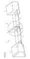
- Figure 3 is a perspective view of a preferred embodiment of a splice bar 1 for a tire tread extrusion die in accordance with the invention. It comprises an upper surface 4 for conveying preferably a non conductive rubber and for extruding an upper tread for instance (also called “cap”), and a lower surface 5 for conveying a preferably conductive rubber and for extruding an under tread for instance (also called “base”). These two surfaces 4, 5 intersect downstream and form an angle in order to splice the two treads or streams.
- the non conductive rubber for the upper tread arrives from an upper side of the splice bar and the conductive rubber arrives from a lower side of the splice bar.
- the main purpose of the splice bar is therefore to guide and convey the two kinds of rubber by bringing them in contact before exiting the extrusion die.
- a final die is typically positioned at the exit of the splice bar in order to shape both the lower and upper treads.
- Blocks 6 and 7 permit a precise and safe positioning of the splice bar 1 and also serve as lateral conveying surface for the rubber.
- the blocks 6, 7 and the upper surface 4 form therefore a first passage and the blocks 6, 7 and the lower surface 5 form a second passage.
- the rubber for the under or base tread is typically a conductive low hysteresis compound and the upper or cap tread is typically a non conductive very low hysteresis compound in which the carbon black is partially replaced by silica.
- the friction of the carbon black particles is the first cause of the tire heating, and consequently an increase in hysteresis.
- the substitution of the carbon black by silica allows a lower heat generation of the tread and therefore a lower rolling resistance.
- Such a compound is however non conductive due to the removal of the carbon black and does not allow the transfer of electrons between the vehicle and the road.
- the presence of a strip of conductive compound in the center of the cap tread makes it possible to discharge the accumulated static electricity.
- an elongate chimney block 2 is arranged on the upper surface 4, preferably approximately at the center with regard to the longitudinal axis.
- This block 2 tapers downstream in order to facilitate the flow of rubber.
- This block preferably extends on the whole upper surface 4 along the flow direction of the rubber, i.e. from a rear surface of the bar until the intersection of the upper and lower surfaces 4, 5.
- a slot 3 is arranged on the front surface of the chimney block 2 for extruding a narrow strip of rubber.
- a passage 10 is made in the splice bar 1 for connecting the slot 3 with the lower passage or the lower surface 5 of conductive rubber.
- This passage 10 is shaped as a slot preferably perpendicular to the lower or base surface 5 and the bottom face of this slot extends essentially parallel to the lower surface 5.
- the passage 10 widens from the front of the block 2 to the rear surface of the splice bar and serves as a chimney for bringing conductive rubber from the lower passage or lower surface 5 to the slot 3 during extrusion.
- the upper bottom of the slot forming the passage 10 is preferably essentially straight and the passage 10 is generally straight until the slot 3 for the base stream of rubber entering the passage 10 upstream, at the vicinity of a third surface.
- this essentially straight passage 10 provides a less tortuous or, said differently, a straighter trajectory for the flow of rubber is illustrated by the arrow in Figure 3 showing the flow of rubber in the passage 10 until the slot 3.
- the sectional shape of the passage 10 in a vertical plane parallel to the flow of gum is trapezoid, more precisely a parallelogram.
- the passage 10 is generally shaped as a slot made in the lower surface 5 extending from the third surface to the front or downstream face of the chimney block 2 thereby being continuous with the slot 3 in the chimney block 2.
- the passage 10 does therefore not comprise any obstacle for the stream of rubber.
- the width of the cross-section of the passage 10 increases from the slot 3 to the third surface. In other words, the passage 10 tapers in the direction of the slot 3.
- the cross-section of the passage 10 is preferably rectangular ranging from the rectangular cross-section of the slot 3 to the rectangular intersection with the third surface 11.
- Section A of Figure 3 is shown in a magnified perspective in Figure 3a , showing more detailed the passage 10, chimney block 2, and slot 3.
- the passage 10 intersects with the third surface and creates an opening there in.
- This opening is preferably rectangular due to rectangular cross-section of the passage.
- This rectangular opening extends vertically over a major part of the third surface, i.e. more than 2/3 of the third surface height counted from its intersection with the lower surface 5 to its intersection with the upper surface 4.
- the height of the opening corresponds approximately to the height of the slot 3. This allows an early entrance in the passage of the base stream of rubber. This portion of the rubber stream which entered upstream the passage encounters a reduced pressure drop in the passage due to its straight shape, i.e.
- a raw bar with a trapezoid cross section is typically first formed by machining an elongate bar of construction steel and then machined to the final shape of the splice bar.
- Figures 4a and 5a illustrate the different fastening positions for the machining of the different surfaces and the chimney on the raw bar.
- Figure 4a illustrates the first fastening position of the splice bar for machining the base side and also the slot 3 and passage 10.
- the lower or base surface 5 faces upward. Due to its geometry and shape the chimney can therefore be machined with the same position of the bar as for the surfaces of the base side.
- the second fastening position of the bar corresponding to the position of figure 3 is shown in figure 5a for machining the cap side. Consequently, only two fastening positions are required for machining the whole bar.
- Figures 4b and 5b show cross sections of the splice bar viewed from different perspectives.
- Figure 5a is the cross section which is indicated by the line B in Figure 4a . It shows chimney block 2, the upper surface 4, passage 10, slot 3, lower surface 5 and block 7. A flow of rubber through the passage 10 is indicated by the arrow.
- Figure 5b is the cross section which is indicated by the line C in Figure 5a . It shows chimney block 2, the upper surface 4, passage 10, slot 3, lower surface 5 and block 6. A flow of rubber through the passage 10 is indicated by the arrow.
- the chimney or passage 10 can however be shaped differently.
- the slot formed by the passage 10 can also taper from the lower surface to the upper bottom.
- the passage can be shaped even closer to the horizontal than in the preferred mode so that the opening defined by the passage in the rear surface 8 comes closer to or contacts the chimney block 2 or the upper surface 4.
- the upper bottom of the passage must not necessarily be totally straight.
- the passage can be shaped such that its upper bottom extending from the slot 3 to the rear surface is slightly curved. This curved portion can be concave or convex.
- the chimney block must not necessarily be positioned at the center. Indeed, the narrow strip of conductive rubber can be off-set from the tread center or even at the tread side but must be positioned in a part of the tread in contact with the road.
Landscapes
- Engineering & Computer Science (AREA)
- Mechanical Engineering (AREA)
- Manufacturing & Machinery (AREA)
- Extrusion Moulding Of Plastics Or The Like (AREA)
- Tyre Moulding (AREA)
Applications Claiming Priority (1)
| Application Number | Priority Date | Filing Date | Title |
|---|---|---|---|
| US12/250,001 US8062017B2 (en) | 2008-10-13 | 2008-10-13 | Splice bar for tire tread extrusion apparatus |
Publications (3)
| Publication Number | Publication Date |
|---|---|
| EP2174770A2 true EP2174770A2 (de) | 2010-04-14 |
| EP2174770A3 EP2174770A3 (de) | 2017-07-26 |
| EP2174770B1 EP2174770B1 (de) | 2018-12-12 |
Family
ID=41343332
Family Applications (1)
| Application Number | Title | Priority Date | Filing Date |
|---|---|---|---|
| EP09171555.7A Active EP2174770B1 (de) | 2008-10-13 | 2009-09-29 | Spleißstange für eine Reifenprofilextrusionsvorrichtung |
Country Status (4)
| Country | Link |
|---|---|
| US (1) | US8062017B2 (de) |
| EP (1) | EP2174770B1 (de) |
| CN (1) | CN101722645B (de) |
| BR (1) | BRPI0904007B1 (de) |
Cited By (5)
| Publication number | Priority date | Publication date | Assignee | Title |
|---|---|---|---|---|
| EP2567802A1 (de) * | 2011-09-12 | 2013-03-13 | The Goodyear Tire & Rubber Company | Unterteilter Dichtungsstreifen und Sperranordnung |
| EP3235623A1 (de) * | 2016-04-22 | 2017-10-25 | Continental Reifen Deutschland GmbH | Steigdüse, extrusionswerkzeug und verfahren zur herstellung eines streifens in einem materialstrang |
| EP3653360A1 (de) * | 2018-11-16 | 2020-05-20 | Continental Reifen Deutschland GmbH | Vorform-vorrichtung und verfahren zur herstellung eines fahrzeugluftreifens mit einem laufstreifenabschnitt mit mindestens zwei gummikomponenten |
| WO2021034438A1 (en) * | 2019-08-21 | 2021-02-25 | Bridgestone Americas Tire Operations, Llc | Apparatus and method for automatic tire ply stitching |
| WO2022002320A1 (de) * | 2020-07-03 | 2022-01-06 | Continental Reifen Deutschland Gmbh | Vorrichtung zum extrudieren eines unvulkanisierten, längsrillen aufweisenden kautschukendlosstreifen zur herstellung eines fahrzeugreifenbauteils, verwendung der vorrichtung zum herstellen eines fahrzeugluftreifens und ein verfahren zum herstellen eines fahrzeugluftreifens sowie einen fahrzeugluftreifen |
Families Citing this family (3)
| Publication number | Priority date | Publication date | Assignee | Title |
|---|---|---|---|---|
| US9878508B2 (en) | 2010-11-30 | 2018-01-30 | The Goodyear Tire & Rubber Company | Stiffness enhanced tread element |
| JP5844242B2 (ja) * | 2012-11-07 | 2016-01-13 | 住友ゴム工業株式会社 | プリフォーマー |
| CN107186967B (zh) * | 2017-07-11 | 2020-05-19 | 山东丰源轮胎制造股份有限公司 | 一种导静电预口型 |
Citations (1)
| Publication number | Priority date | Publication date | Assignee | Title |
|---|---|---|---|---|
| US6746227B2 (en) | 2001-06-19 | 2004-06-08 | The Goodyear Tire & Rubber Company | Tire tread die |
Family Cites Families (8)
| Publication number | Priority date | Publication date | Assignee | Title |
|---|---|---|---|---|
| IT1290520B1 (it) * | 1997-04-03 | 1998-12-04 | Pirelli | Metodo ed apparato di estrusione per realizzare fasce battistrada per pneumatici di veicoli |
| US6294119B1 (en) * | 1997-12-26 | 2001-09-25 | Bridgestone Corporation | Production of unvulcanized tread rubber for pneumatic tires |
| US6951233B1 (en) * | 1998-02-26 | 2005-10-04 | Compagnie Generale Des Etablissements Michelin-Michelin & Cie | Electrically conductive tire and apparatus and process for extruding elements which have been made conductive |
| FR2775220A1 (fr) * | 1998-02-26 | 1999-08-27 | Michelin & Cie | Pneumatique conducteur d'electricite et appareillage d'extrusion d'un profile avec insert conducteur |
| EP1241026B1 (de) * | 2001-03-12 | 2007-03-07 | Bridgestone Corporation | Reifen |
| BR0205350B1 (pt) * | 2001-05-16 | 2010-10-19 | processo de obtenção de um elemento à base de misturas borrachosas destinado à fabricação de um pnemático, e, aparelhagem de co-extrusão de misturas borrachosas. | |
| JP4277988B2 (ja) * | 2003-06-26 | 2009-06-10 | 横浜ゴム株式会社 | タイヤ用トレッドゴムの成形装置 |
| KR100513240B1 (ko) * | 2003-11-04 | 2005-09-07 | 금호타이어 주식회사 | 트레드에 방전로를 갖는 타이어 압출성형장치의 다이세트 |
-
2008
- 2008-10-13 US US12/250,001 patent/US8062017B2/en not_active Expired - Fee Related
-
2009
- 2009-09-29 EP EP09171555.7A patent/EP2174770B1/de active Active
- 2009-10-01 BR BRPI0904007-2A patent/BRPI0904007B1/pt not_active IP Right Cessation
- 2009-10-13 CN CN200910179297.1A patent/CN101722645B/zh not_active Expired - Fee Related
Patent Citations (1)
| Publication number | Priority date | Publication date | Assignee | Title |
|---|---|---|---|---|
| US6746227B2 (en) | 2001-06-19 | 2004-06-08 | The Goodyear Tire & Rubber Company | Tire tread die |
Cited By (9)
| Publication number | Priority date | Publication date | Assignee | Title |
|---|---|---|---|---|
| EP2567802A1 (de) * | 2011-09-12 | 2013-03-13 | The Goodyear Tire & Rubber Company | Unterteilter Dichtungsstreifen und Sperranordnung |
| US8617334B2 (en) | 2011-09-12 | 2013-12-31 | The Goodyear Tire & Rubber Company | Method and apparatus for making a compartmentalized tire sealant strip |
| US9844982B2 (en) | 2011-09-12 | 2017-12-19 | The Goodyear Tire & Rubber Company | Method and apparatus for making a compartmentalized tire sealant strip |
| US10737539B2 (en) | 2011-09-12 | 2020-08-11 | The Goodyear Tire & Rubber Company | Method and apparatus for making a compartmentalized tire sealant strip |
| EP3235623A1 (de) * | 2016-04-22 | 2017-10-25 | Continental Reifen Deutschland GmbH | Steigdüse, extrusionswerkzeug und verfahren zur herstellung eines streifens in einem materialstrang |
| EP3653360A1 (de) * | 2018-11-16 | 2020-05-20 | Continental Reifen Deutschland GmbH | Vorform-vorrichtung und verfahren zur herstellung eines fahrzeugluftreifens mit einem laufstreifenabschnitt mit mindestens zwei gummikomponenten |
| WO2021034438A1 (en) * | 2019-08-21 | 2021-02-25 | Bridgestone Americas Tire Operations, Llc | Apparatus and method for automatic tire ply stitching |
| US11691369B2 (en) | 2019-08-21 | 2023-07-04 | Bridgestone Americas Tire Operations, Llc | Apparatus and method for automatic tire ply sitiching |
| WO2022002320A1 (de) * | 2020-07-03 | 2022-01-06 | Continental Reifen Deutschland Gmbh | Vorrichtung zum extrudieren eines unvulkanisierten, längsrillen aufweisenden kautschukendlosstreifen zur herstellung eines fahrzeugreifenbauteils, verwendung der vorrichtung zum herstellen eines fahrzeugluftreifens und ein verfahren zum herstellen eines fahrzeugluftreifens sowie einen fahrzeugluftreifen |
Also Published As
| Publication number | Publication date |
|---|---|
| BRPI0904007A2 (pt) | 2010-07-20 |
| US8062017B2 (en) | 2011-11-22 |
| CN101722645B (zh) | 2014-10-01 |
| EP2174770B1 (de) | 2018-12-12 |
| EP2174770A3 (de) | 2017-07-26 |
| BRPI0904007B1 (pt) | 2020-03-17 |
| CN101722645A (zh) | 2010-06-09 |
| US20100092589A1 (en) | 2010-04-15 |
Similar Documents
| Publication | Publication Date | Title |
|---|---|---|
| EP2174770B1 (de) | Spleißstange für eine Reifenprofilextrusionsvorrichtung | |
| US7036652B2 (en) | Vibration-type parts feeding method and device | |
| EP2719607B1 (de) | Struktur für den hinteren teil eines fahrzeugs | |
| JP5039127B2 (ja) | 未加硫ゴム押出装置及び未加硫ゴムの製造方法 | |
| US6746227B2 (en) | Tire tread die | |
| US7258827B2 (en) | Method for extruding unvulcanized rubber | |
| KR101649065B1 (ko) | 절연섹션, 급전레일 및 궤도계 교통시스템 | |
| JP4277988B2 (ja) | タイヤ用トレッドゴムの成形装置 | |
| US20110086120A1 (en) | Extrusion head as well as an extrusion device fitted with such an extrusion head | |
| JP5566588B2 (ja) | 未加硫ゴム押出機 | |
| US20090205915A1 (en) | Current collecting contact member | |
| KR20140105012A (ko) | 절연 섹션, 급전 레일 및 궤도계 교통 시스템 | |
| US8016580B2 (en) | Assembly and a method for extruding a tire component | |
| JP4609891B2 (ja) | ゴム押出ヘッド及びそれを備えたゴム押出機 | |
| JPH0994831A (ja) | 加硫成形金型及びラジアルタイヤ | |
| JP4915784B2 (ja) | ゴム成形装置及びゴム部材の成形方法 | |
| CN218054831U (zh) | 一种玻璃导槽c柱 | |
| US20060057242A1 (en) | Mold-half for an device for the producing tubes provided with cross ribs | |
| CN211027814U (zh) | 一种汽车中冷器内翅片出料扶正器 | |
| US10427370B2 (en) | Molding element for manufacturing a noise reducing tread | |
| JP6797364B2 (ja) | 押出機用口金 | |
| JP5390010B1 (ja) | ワイヤガイド、ワイヤガイドアッセンブリ、およびワイヤ放電加工機 | |
| JP2007168385A (ja) | ゴム成形装置及びゴム成形方法 | |
| CN103964286A (zh) | 乘客传送设备以及乘客传送设备的梯级 | |
| US20180272567A1 (en) | Molding element for manufacturing a noise reducing tread |
Legal Events
| Date | Code | Title | Description |
|---|---|---|---|
| PUAI | Public reference made under article 153(3) epc to a published international application that has entered the european phase |
Free format text: ORIGINAL CODE: 0009012 |
|
| AK | Designated contracting states |
Kind code of ref document: A2 Designated state(s): AT BE BG CH CY CZ DE DK EE ES FI FR GB GR HR HU IE IS IT LI LT LU LV MC MK MT NL NO PL PT RO SE SI SK SM TR |
|
| AX | Request for extension of the european patent |
Extension state: AL BA RS |
|
| PUAL | Search report despatched |
Free format text: ORIGINAL CODE: 0009013 |
|
| AK | Designated contracting states |
Kind code of ref document: A3 Designated state(s): AT BE BG CH CY CZ DE DK EE ES FI FR GB GR HR HU IE IS IT LI LT LU LV MC MK MT NL NO PL PT RO SE SI SK SM TR |
|
| AX | Request for extension of the european patent |
Extension state: AL BA RS |
|
| RIC1 | Information provided on ipc code assigned before grant |
Ipc: B29C 47/04 20060101AFI20170620BHEP Ipc: B29C 47/14 20060101ALI20170620BHEP |
|
| STAA | Information on the status of an ep patent application or granted ep patent |
Free format text: STATUS: REQUEST FOR EXAMINATION WAS MADE |
|
| 17P | Request for examination filed |
Effective date: 20180126 |
|
| RBV | Designated contracting states (corrected) |
Designated state(s): AT BE BG CH CY CZ DE DK EE ES FI FR GB GR HR HU IE IS IT LI LT LU LV MC MK MT NL NO PL PT RO SE SI SK SM TR |
|
| GRAP | Despatch of communication of intention to grant a patent |
Free format text: ORIGINAL CODE: EPIDOSNIGR1 |
|
| STAA | Information on the status of an ep patent application or granted ep patent |
Free format text: STATUS: GRANT OF PATENT IS INTENDED |
|
| INTG | Intention to grant announced |
Effective date: 20180704 |
|
| GRAS | Grant fee paid |
Free format text: ORIGINAL CODE: EPIDOSNIGR3 |
|
| GRAA | (expected) grant |
Free format text: ORIGINAL CODE: 0009210 |
|
| STAA | Information on the status of an ep patent application or granted ep patent |
Free format text: STATUS: THE PATENT HAS BEEN GRANTED |
|
| REG | Reference to a national code |
Ref country code: DE Ref legal event code: R079 Ref document number: 602009056146 Country of ref document: DE Free format text: PREVIOUS MAIN CLASS: B29C0047040000 Ipc: B29C0048160000 |
|
| AK | Designated contracting states |
Kind code of ref document: B1 Designated state(s): AT BE BG CH CY CZ DE DK EE ES FI FR GB GR HR HU IE IS IT LI LT LU LV MC MK MT NL NO PL PT RO SE SI SK SM TR |
|
| REG | Reference to a national code |
Ref country code: GB Ref legal event code: FG4D |
|
| REG | Reference to a national code |
Ref country code: CH Ref legal event code: EP |
|
| REG | Reference to a national code |
Ref country code: AT Ref legal event code: REF Ref document number: 1075355 Country of ref document: AT Kind code of ref document: T Effective date: 20181215 |
|
| REG | Reference to a national code |
Ref country code: DE Ref legal event code: R096 Ref document number: 602009056146 Country of ref document: DE |
|
| REG | Reference to a national code |
Ref country code: IE Ref legal event code: FG4D |
|
| REG | Reference to a national code |
Ref country code: NL Ref legal event code: MP Effective date: 20181212 |
|
| REG | Reference to a national code |
Ref country code: LT Ref legal event code: MG4D |
|
| PG25 | Lapsed in a contracting state [announced via postgrant information from national office to epo] |
Ref country code: NO Free format text: LAPSE BECAUSE OF FAILURE TO SUBMIT A TRANSLATION OF THE DESCRIPTION OR TO PAY THE FEE WITHIN THE PRESCRIBED TIME-LIMIT Effective date: 20190312 Ref country code: LV Free format text: LAPSE BECAUSE OF FAILURE TO SUBMIT A TRANSLATION OF THE DESCRIPTION OR TO PAY THE FEE WITHIN THE PRESCRIBED TIME-LIMIT Effective date: 20181212 Ref country code: HR Free format text: LAPSE BECAUSE OF FAILURE TO SUBMIT A TRANSLATION OF THE DESCRIPTION OR TO PAY THE FEE WITHIN THE PRESCRIBED TIME-LIMIT Effective date: 20181212 Ref country code: BG Free format text: LAPSE BECAUSE OF FAILURE TO SUBMIT A TRANSLATION OF THE DESCRIPTION OR TO PAY THE FEE WITHIN THE PRESCRIBED TIME-LIMIT Effective date: 20190312 Ref country code: ES Free format text: LAPSE BECAUSE OF FAILURE TO SUBMIT A TRANSLATION OF THE DESCRIPTION OR TO PAY THE FEE WITHIN THE PRESCRIBED TIME-LIMIT Effective date: 20181212 Ref country code: LT Free format text: LAPSE BECAUSE OF FAILURE TO SUBMIT A TRANSLATION OF THE DESCRIPTION OR TO PAY THE FEE WITHIN THE PRESCRIBED TIME-LIMIT Effective date: 20181212 Ref country code: FI Free format text: LAPSE BECAUSE OF FAILURE TO SUBMIT A TRANSLATION OF THE DESCRIPTION OR TO PAY THE FEE WITHIN THE PRESCRIBED TIME-LIMIT Effective date: 20181212 |
|
| REG | Reference to a national code |
Ref country code: AT Ref legal event code: MK05 Ref document number: 1075355 Country of ref document: AT Kind code of ref document: T Effective date: 20181212 |
|
| PG25 | Lapsed in a contracting state [announced via postgrant information from national office to epo] |
Ref country code: GR Free format text: LAPSE BECAUSE OF FAILURE TO SUBMIT A TRANSLATION OF THE DESCRIPTION OR TO PAY THE FEE WITHIN THE PRESCRIBED TIME-LIMIT Effective date: 20190313 Ref country code: SE Free format text: LAPSE BECAUSE OF FAILURE TO SUBMIT A TRANSLATION OF THE DESCRIPTION OR TO PAY THE FEE WITHIN THE PRESCRIBED TIME-LIMIT Effective date: 20181212 |
|
| PG25 | Lapsed in a contracting state [announced via postgrant information from national office to epo] |
Ref country code: NL Free format text: LAPSE BECAUSE OF FAILURE TO SUBMIT A TRANSLATION OF THE DESCRIPTION OR TO PAY THE FEE WITHIN THE PRESCRIBED TIME-LIMIT Effective date: 20181212 |
|
| PG25 | Lapsed in a contracting state [announced via postgrant information from national office to epo] |
Ref country code: PL Free format text: LAPSE BECAUSE OF FAILURE TO SUBMIT A TRANSLATION OF THE DESCRIPTION OR TO PAY THE FEE WITHIN THE PRESCRIBED TIME-LIMIT Effective date: 20181212 Ref country code: CZ Free format text: LAPSE BECAUSE OF FAILURE TO SUBMIT A TRANSLATION OF THE DESCRIPTION OR TO PAY THE FEE WITHIN THE PRESCRIBED TIME-LIMIT Effective date: 20181212 Ref country code: PT Free format text: LAPSE BECAUSE OF FAILURE TO SUBMIT A TRANSLATION OF THE DESCRIPTION OR TO PAY THE FEE WITHIN THE PRESCRIBED TIME-LIMIT Effective date: 20190412 |
|
| PG25 | Lapsed in a contracting state [announced via postgrant information from national office to epo] |
Ref country code: IS Free format text: LAPSE BECAUSE OF FAILURE TO SUBMIT A TRANSLATION OF THE DESCRIPTION OR TO PAY THE FEE WITHIN THE PRESCRIBED TIME-LIMIT Effective date: 20190412 Ref country code: RO Free format text: LAPSE BECAUSE OF FAILURE TO SUBMIT A TRANSLATION OF THE DESCRIPTION OR TO PAY THE FEE WITHIN THE PRESCRIBED TIME-LIMIT Effective date: 20181212 Ref country code: EE Free format text: LAPSE BECAUSE OF FAILURE TO SUBMIT A TRANSLATION OF THE DESCRIPTION OR TO PAY THE FEE WITHIN THE PRESCRIBED TIME-LIMIT Effective date: 20181212 Ref country code: SM Free format text: LAPSE BECAUSE OF FAILURE TO SUBMIT A TRANSLATION OF THE DESCRIPTION OR TO PAY THE FEE WITHIN THE PRESCRIBED TIME-LIMIT Effective date: 20181212 Ref country code: SK Free format text: LAPSE BECAUSE OF FAILURE TO SUBMIT A TRANSLATION OF THE DESCRIPTION OR TO PAY THE FEE WITHIN THE PRESCRIBED TIME-LIMIT Effective date: 20181212 |
|
| REG | Reference to a national code |
Ref country code: DE Ref legal event code: R097 Ref document number: 602009056146 Country of ref document: DE |
|
| PLBE | No opposition filed within time limit |
Free format text: ORIGINAL CODE: 0009261 |
|
| STAA | Information on the status of an ep patent application or granted ep patent |
Free format text: STATUS: NO OPPOSITION FILED WITHIN TIME LIMIT |
|
| PG25 | Lapsed in a contracting state [announced via postgrant information from national office to epo] |
Ref country code: SI Free format text: LAPSE BECAUSE OF FAILURE TO SUBMIT A TRANSLATION OF THE DESCRIPTION OR TO PAY THE FEE WITHIN THE PRESCRIBED TIME-LIMIT Effective date: 20181212 Ref country code: DK Free format text: LAPSE BECAUSE OF FAILURE TO SUBMIT A TRANSLATION OF THE DESCRIPTION OR TO PAY THE FEE WITHIN THE PRESCRIBED TIME-LIMIT Effective date: 20181212 Ref country code: AT Free format text: LAPSE BECAUSE OF FAILURE TO SUBMIT A TRANSLATION OF THE DESCRIPTION OR TO PAY THE FEE WITHIN THE PRESCRIBED TIME-LIMIT Effective date: 20181212 |
|
| 26N | No opposition filed |
Effective date: 20190913 |
|
| PG25 | Lapsed in a contracting state [announced via postgrant information from national office to epo] |
Ref country code: TR Free format text: LAPSE BECAUSE OF FAILURE TO SUBMIT A TRANSLATION OF THE DESCRIPTION OR TO PAY THE FEE WITHIN THE PRESCRIBED TIME-LIMIT Effective date: 20181212 |
|
| PG25 | Lapsed in a contracting state [announced via postgrant information from national office to epo] |
Ref country code: MC Free format text: LAPSE BECAUSE OF FAILURE TO SUBMIT A TRANSLATION OF THE DESCRIPTION OR TO PAY THE FEE WITHIN THE PRESCRIBED TIME-LIMIT Effective date: 20181212 |
|
| REG | Reference to a national code |
Ref country code: CH Ref legal event code: PL |
|
| PG25 | Lapsed in a contracting state [announced via postgrant information from national office to epo] |
Ref country code: LU Free format text: LAPSE BECAUSE OF NON-PAYMENT OF DUE FEES Effective date: 20190929 Ref country code: IE Free format text: LAPSE BECAUSE OF NON-PAYMENT OF DUE FEES Effective date: 20190929 Ref country code: CH Free format text: LAPSE BECAUSE OF NON-PAYMENT OF DUE FEES Effective date: 20190930 Ref country code: LI Free format text: LAPSE BECAUSE OF NON-PAYMENT OF DUE FEES Effective date: 20190930 |
|
| REG | Reference to a national code |
Ref country code: BE Ref legal event code: MM Effective date: 20190930 |
|
| PG25 | Lapsed in a contracting state [announced via postgrant information from national office to epo] |
Ref country code: BE Free format text: LAPSE BECAUSE OF NON-PAYMENT OF DUE FEES Effective date: 20190930 |
|
| GBPC | Gb: european patent ceased through non-payment of renewal fee |
Effective date: 20190929 |
|
| PG25 | Lapsed in a contracting state [announced via postgrant information from national office to epo] |
Ref country code: GB Free format text: LAPSE BECAUSE OF NON-PAYMENT OF DUE FEES Effective date: 20190929 |
|
| PG25 | Lapsed in a contracting state [announced via postgrant information from national office to epo] |
Ref country code: CY Free format text: LAPSE BECAUSE OF FAILURE TO SUBMIT A TRANSLATION OF THE DESCRIPTION OR TO PAY THE FEE WITHIN THE PRESCRIBED TIME-LIMIT Effective date: 20181212 |
|
| PG25 | Lapsed in a contracting state [announced via postgrant information from national office to epo] |
Ref country code: MT Free format text: LAPSE BECAUSE OF FAILURE TO SUBMIT A TRANSLATION OF THE DESCRIPTION OR TO PAY THE FEE WITHIN THE PRESCRIBED TIME-LIMIT Effective date: 20181212 Ref country code: HU Free format text: LAPSE BECAUSE OF FAILURE TO SUBMIT A TRANSLATION OF THE DESCRIPTION OR TO PAY THE FEE WITHIN THE PRESCRIBED TIME-LIMIT; INVALID AB INITIO Effective date: 20090929 |
|
| PGFP | Annual fee paid to national office [announced via postgrant information from national office to epo] |
Ref country code: FR Payment date: 20210812 Year of fee payment: 13 |
|
| PG25 | Lapsed in a contracting state [announced via postgrant information from national office to epo] |
Ref country code: MK Free format text: LAPSE BECAUSE OF FAILURE TO SUBMIT A TRANSLATION OF THE DESCRIPTION OR TO PAY THE FEE WITHIN THE PRESCRIBED TIME-LIMIT Effective date: 20181212 |
|
| PGFP | Annual fee paid to national office [announced via postgrant information from national office to epo] |
Ref country code: IT Payment date: 20220811 Year of fee payment: 14 Ref country code: DE Payment date: 20220609 Year of fee payment: 14 |
|
| PG25 | Lapsed in a contracting state [announced via postgrant information from national office to epo] |
Ref country code: FR Free format text: LAPSE BECAUSE OF NON-PAYMENT OF DUE FEES Effective date: 20220930 |
|
| REG | Reference to a national code |
Ref country code: DE Ref legal event code: R119 Ref document number: 602009056146 Country of ref document: DE |
|
| PG25 | Lapsed in a contracting state [announced via postgrant information from national office to epo] |
Ref country code: DE Free format text: LAPSE BECAUSE OF NON-PAYMENT OF DUE FEES Effective date: 20240403 |